Embed Size (px)
Citation preview
HAL Id: hal-00783985https://hal.archives-ouvertes.fr/hal-00783985
Submitted on 6 Feb 2013
HAL is a multi-disciplinary open accessarchive for the deposit and dissemination of sci-entific research documents, whether they are pub-lished or not. The documents may come fromteaching and research institutions in France orabroad, or from public or private research centers.
L’archive ouverte pluridisciplinaire HAL, estdestinée au dépôt et à la diffusion de documentsscientifiques de niveau recherche, publiés ou non,émanant des établissements d’enseignement et derecherche français ou étrangers, des laboratoirespublics ou privés.
Integration of 3D and multispectral data for culturalheritage applications: Survey and perspectives
Camille Simon, Alamin Mansouri, Marzani Franck, Boochs Frank
To cite this version:Camille Simon, Alamin Mansouri, Marzani Franck, Boochs Frank. Integration of 3D and multispec-tral data for cultural heritage applications: Survey and perspectives. Image and Vision Computing,Elsevier, 2013, 31 (1), pp.91-102. �hal-00783985�

Integration of 3D and multispectral data for cultural
heritage applications: survey and perspectives
Camille Simon Chanea,b,∗, Alamin Mansouric, Franck S. Marzania, FrankBoochsb
ale2i, Université de Bourgogne, Bâtiment Mirande - UFR Sciences & Techniques,
B.P. 47870 - 21078 Dijon Cedex, France.bi3mainz, Institute for Spatial Information and Surveying Technology,
University of Applied Sciences Mainz, Germany.cle2i, Université de Bourgogne, B.P. 16, Route des plaines de l'Yonne,
89010 Auxerre Cedex, France.
Abstract
Cultural heritage is increasingly put through imaging systems such as multispec-tral cameras and 3D scanners. Though these acquisition systems are often usedindependently, they collect complementary information (spectral vs. spatial)used for the study, archiving and visualization of cultural heritage. Recording3D and multispectral data in a single coordinate system enhances the potentialinsights in data analysis.
We present the state of the art of such acquisition systems and their appli-cations for the study of cultural heritage. We also describe existing registrationtechniques that can be used to obtain 3D models with multispectral texture andexplore the idea of optically tracking acquisition systems to ensure an easy andprecise registration.
Keywords: cultural heritage, multispectral imaging, 3D digitization,registration, data fusion, photogrammetry
1. Introduction
Cultural heritage is a favorite application of the image processing and com-puter graphics community. We enjoy developing tools to study and analyzethese unique and precious surfaces. We strive to create accurate virtual repre-sentations of cultural heritage objects, even though this might not be the goalof conservators. When studying mostly two dimensional objects such as paint-ings, multispectral imaging is the path of predilection. For statues, we favor 3Ddigitization.
∗Corresponding authorEmail addresses: [email protected] (Camille Simon Chane),
[email protected] (Alamin Mansouri), [email protected](Franck S. Marzani), [email protected] (Frank Boochs)
Preprint submitted to Image and Vision Computing February 6, 2013
Of course it is not un-common to create 3D models of paintings, and mul-tispectral imaging is sometimes used on non-planar objects. But the growinginterest is in combining these complementary datasets to create 3D models withmultispectral texture. Such models can be used for virtual reality applications.Most importantly, they are an improvement on 3D models for the analysis andstudy of works of art. Conservators can gain much insight from these augmentedmodels.
However, multispectral cameras and 3D digitization systems are built on dif-ferent concepts. There are di�culties associated with both developing integratedmultispectral 3D digitization systems and registering independent datasets viapost-processing. Thus, creating multispectral 3D models is not a straightfor-ward task.
Our goal is to review and centralize the techniques (acquisition systems andalgorithms) that can be used to obtain multispectral 3D models of culturalheritage objects. An overview of the existing applications of each of these tech-niques in the �eld of cultural heritage is meant to inform the reader of thepossible uses of such data. This article is voluntarily high-level and meant as aresource survey.
Our scope is limited to the study of cultural heritage objects as opposedto full buildings, archaeological sites or cities. We use the term "object" todescribe anything from the smallest archaeological fragment to 5m high statuesand wall paintings that cover full rooms. Systems and algorithms optimized forthe digitization of full cities or archaeological sites are only mentioned to theextent that they can be adapted to smaller volumes.
We only describe non-contact acquisition systems since contact acquisitionsystems may damage the object and are thus rarely used for the study of culturalheritage. We foreground portable systems that can be used directly in museums,monuments or any other non-laboratory site. We also highlight �exible solutionsthat can be adapted to the variability of the objects under study. In heritagesettings, objects of similar size, shape and material have an individual historythat can in�uence the acquisition process and systems with variable �eld-of-viewand resolution are most appreciated.
This review is organized as follows: Section 2 presents the state-of-the-artin multispectral acquisitions and multispectral data processing, with an accenton systems developed for the analysis of cultural heritage objects and the pos-sible uses of such data. Section 3 presents 3D digitization techniques, great 3Ddigitization campaigns and the various uses of 3D models for conservation. Wethen present the most common methods used to obtain 3D data with multispec-tral or color texture, using either integrated devices or registration algorithms.Finally we describe how photogrammetry-based optical tracking can be used toease multimodal registration.
2
2. Multispectral imaging
2.1. Limitations of color imaging
The perceived color of an object is a function of the spectral re�ectanceof its surface, the spectral distribution of the illumination and the spectralsensitivities of the cones in the eye, at the least. A recorded color image isthus both device and illuminant dependent. When a surface is acquired under agiven illuminant, it is impossible to estimate the surface color accurately underanother illuminant in the absence of additional information on the spectralre�ectance. In conventional color imaging, each pixel is characterized by threecomponents such as red, green and blue. Theoretically, these three componentsare necessary and su�cient to synthesize any color from a colorimetric point ofview, but imaging systems based on three primary colors present a number oflimitations:
• Conventional RGB chips violate the Luther rule which states that a sensorcan distinguish the same colors as the human eye only if the spectralresponses of this sensor can be obtained by a linear combination of the S,M and L eye cone responses.
• Due to metamerism, two surfaces with strongly di�erent spectra can ap-pear identical under a given illuminant and completely di�erent underanother.
• The use of color information in image databases is limited by the fact thatrecorded RGB signals depend on the acquisition devices, the illuminantsand image preprocessing.
These drawbacks result from the weak spectral resolution of conventionalcolor imaging systems. A high spectral resolution allows a better estimationof the surface re�ectance. This in turn permits a better characterization of itsintrinsic physical properties regardless of the acquisition conditions (illuminant,acquisition device). It is possible to acquire color-accurate images with conven-tional trichromatic sensors by working in adapted color spaces such as CIELAB[1]. However systems that acquire more than three spectral components per-mit a better estimation of the re�ectance. CIE recommends that multispectralacquisition systems acquire 31 bands between 400 nm and 700 nm (that is, onechannel every 10 nm) but Berns et al. [2] state comparable spectral precisioncan be obtained using less than 10 bands. There is thus a great variability inthe number of bands acquired by multispectral acquisition systems.
2.2. Multispectral acquisition systems
As opposed to spectrophotometers which acquire spectra with nanometricprecision in a single spot, multispectral imaging systems acquire data along twospatial dimensions and one spectral dimension. This is usually referred to as amultispectral cube. This data is generally acquired along two dimensions at atime and scanned across the third dimension. There are thus two acquisition
3

paradigms. In the �rst case successive images of a given area are acquired atvarying wavelengths. In the second case spatio-spectral images are acquired andthere must be some motion of the acquisition sensor to acquire data along theother spatial dimension [3].
Multispcetral scanners and imagers are generally categorized based on the�ltering technology used:
Optical �lters These �lters (most often interference �lters) are generally moun-ted on a rotating wheel or another mechanical device. The �lters are se-quentially positioned in front of a panchormatic sensor to acquire a singleimage in the range of the �lter [4�7]. Various algorithms can be used tocompensate geometric distortion [4, 5], longitudinal aberrations [8] andghosting [9] introduced by the �lter-wheel. The use of optical �lters hasthe disadvantage of creating a �x setup, with cumbersome �lter-wheels.The size of the �lter wheel limits the number of spectral bands. The longacquisition times can be reduced by using a synchronized �ash [10] thoughthis is not adapted to the study of cultural heritage objects.
Electronically tunable �lters LCTFs (Liquid Crystal Tunable Filters), AOTFs(Acousto-Optic Tunable Filters) and adapted Fabry-Perot devices allowto electronically select the �ltering band. This greatly speeds up the ac-quisition process compared to �lter-wheel systems [11�14]. Devices basedon such �lters are also very �exible since the number and width of bandscan be changed programmatically.
Poger and Angelopopoulou [15] have compared the characteristics of thesethree types of electronically tunable �lters. Most importantly, AOTF havea high transmission rate (98%) but they require collimated light whileLCTF and Fabry-Perot devices su�er from a low transmission rate (lowerthan 50%).
Extension of Color Filter Arrays (CFAs) Instead of positioning �lters infront of the sensor, extended mosaicking of CFAs is used to obtain morethan three color bands [2, 16, 17]. The practical use of this type of multi-spectral system is still being investigated.
Tunable Light Sources It is possible to successively project light at di�erentwavelengths on the object (excitation �ltering) instead of �ltering the lightre�ected from the object (emission �ltering). A common strategy is to usemultiplex multicolor LED illumination as a tunable light source [18�20].This solution is gaining popularity with the increasing availability of LEDsin an increasing variety of colors. It is also possible to use a slide projectorand color �lters [21] or DLPs [22] as a tunable light source.
To avoid contaminating the acquisition with stray light, multispectralacquisition systems based on excitation �ltering must be used either incontact with the object, or in a dark environment. Because of theseconstraints, few multispectral imagers for cultural heritage are built onexcitation �ltering.
4
Additionally, spatially varying �lters [23] or prisms [24] can be used in scan-ning devices to acquire wide-�eld of view multispectral images or multispectralvideos.
Among the recent advances in multispectral imaging Kawakami et al. [25]combined a high spatial resolution RGB sensor with a low resolution MS camerato obtain high spatial resolution spectral images. The results are promisingthough the method produces some errors and is thus not mature enough to beused for the analysis of cultural heritage object.
2.3. Multispectral imaging for cultural heritage
Many multispectral acquisition systems have been developed for the study ofcultural heritage. We present a selected few, starting with the most well knownand large projects and �nishing with lab-scale projects and the applications ofmultispectral imaging for cultural heritage. Table 1 summarizes the technicalcharacteristics of existing acquisition systems developed for the study of culturalheritage.
In the early 1990's the VASARI project [26] focused on the developmentof a 12 band multispectral acquisition system based on a �lter-wheel tunablelight source. Using a 3000× 2000 pixels CCD and a gantry the system captured20 000 × 20 000pixel acquisitions. At the time, such high spectral resolutioncame at a high cost : it took about 3 hours to digitize a 1m × 1m painting.However, this was a remarkable project that opened the path to multispectralimaging of paintings for conservation, material identi�cation and multispectralprinting.
The European project CRISATEL [27] also aimed at developing a multi-spectral acquisition system for the analysis of paintings. The device is based ona linear CCD (12 000pixels) which is mechanically displaced to acquire 20 000vertical lines. 13 interference �lters are used (10 in the visible and 3 in thenear infrared) to cover the 380 nm to 1000nm range. This multispectral camerais used in conjunction with a dedicated synchronized lighting system. With acomparable spatial resolution to the VASARI camera, this device digitized thesurface of the Mona Lisa (78 cm×82 cm) in an hour and a half [29]. This systemis also less bulky than the one developed by the VASARI team.
Both the VASARI and the CRISATEL systems were developed within largeprojects, but it is possible to develop small-scale multispectral acquisition sys-tems with reasonable means [6, 14, 21, 28]. These four systems are image-basedand they acquire much smaller areas than the previous two systems. How-ever, their acquisition time is less than a few minutes and tiling can be usedto acquire larger areas. The system developed by Pelagotti et al. [6] is partic-ularly impressive as it acquires visible re�ectance, infrared re�ectography andUV-�uorescence, a combination of data most adapted for the study of paintings.
Multispectral data alone lacks the spectral resolution necessary to distin-guish artist pigments [26] but it can be used as a complement to spot tech-niques for material identi�cation [6, 30] or to distinguish metamers [30, 31].Multispectral imaging has been used to increase the readability of palimpsests
5

Table
1:Multispectralsystem
sdeveloped
forculturalheritageapplicationsgiven
inroughchronologicalorder.
References
Filteringtype
Spectralbands
Spectralrange
Imagesize
Dynam
icrange
(nm)
(pixels)
(bits)
VASA
RIproject[26]
Tunablelight
12450−1000
20000×20000
8CRISATELproject[27]
Interferential
13400−1000
12000×30000
12Novatiet
al.[14]
LCTF
31400−700
1392×1040
12Berns
etal.[28]
CFA
6380−750
22megapixels
16Pelagottiet
al.[6]
Interferential
15380−1130
3072×2048
14
6

dk
CCD
c(λ) o(λ) tk(λ)
r(λ)
I(λ)
Figure 1: Spectral model of the acquisition process in emission �ltering multispectral acqui-sition systems. I (λ) represents the spectral radiance of the illuminant, r (λ) is the spectralre�ectance of the surface, tk (λ) denotes the spectral transmittance related to the kth �lter,o (λ) is the spectral transmittance of the optical system, c (λ) is the spectral sensitivity of thecamera.
using pseudocoloring [32�34]. In the same vein, virtually restoring the originalcolors of paintings [35] can increase their readability. Multispectral images canbe used for the analysis of cracks and the study of varnish aging [29, 36]. This isboth important to understand the history of the painting and to guide a virtualrestoration. The use of multispectral data for virtual archives is also a commonapplication [21, 26].
The possibility to view the digitized surface under arbitrary illuminants[21, 27] is a real strength of multispectral data. This can be used to viewdigitized versions of the artworks under broad daylight when such conditionscould damage fragile pigments such as those of watercolors. It is also possibleto simulate the illumination environment before exhibiting a work of art. Mul-tispcetral acquisitions are also the �rst necessary step for multispectral printingusing 6 or 7 color inks [28, 37].
2.4. Re�ectance estimation from multispectral data
Multispectral imaging aims at acquiring the re�ectance of the surface ofthe scene rather than its color. Increasing the number of acquisition channelseases this process but re�ectance estimation from the acquired images is nottrivial and requires appropriate models. The most used spectral model of theacquisition chain in color and multispectral systems is illustrated �gure 1.
Using the notations introduced in this �gure and with ηk representing thespectral noise for the kth channel with k = 1 . . .K, the camera output dk, relatedto the channel k for a single pixel of the image is given by:
dk =
∫ λmax
λmin
I (λ) r (λ) o (λ) c (λ) tk (λ) dλ+ ηk. (1)
7
If we assume that the noise is removed by preprocessing [4, 38], and assumea linear optoelectronic transfer function, we can replace I (λ), c (λ), o (λ) andtk (λ) by the spectral sensitivity Sk (λ) of the kth channel. Equation 1 thusbecomes:
dk =
∫ λmax
λmin
Sk (λ) r (λ) dλ. (2)
By regular sampling of the spectral range at N wavelengths, equation 2 can bewritten in matrix notation as follows:
dk = STk (λ) r (λ) , (3)
where STk (λ) = [sk (λ1) sk (λ2) . . . sk (λN )]T is the vector which describes the
spectral sensitivity of the kth channel of the acquisition system, r (λ) = [r (λ1) r (λ2) . . . r (λN )]T
is the vector of the sampled spectral re�ectances of the scene and T is the trans-pose vector operator. If we consider a system with all channels, equation 3 canbe written as:
d = ST r, (4)
where d is the vector containing all dk camera outputs and S = [s1 s2 . . . sK ]T
is the matrix containing the channels' spectral sensitivities Sk. The �nal goalis to recover r from the camera output given by equation 4. This is obtainedby �nding an operator Q that satis�es r̃ = Q d. Many methods permit thisestimation [39�45] , most of which can be categorized depending on how thematrix S is determined:
• If S is obtained by a direct physical system characterization [46�49], theoperator Q is the inverse of S. However, since S is usually not a squarematrix, its inverse does not exist. Only a pseudo-inverse or another regu-larized inverse such as Wiener can be calculated. Thus Q = S+ where +
is the pseudo-inverse operator.
• S can also be obtained indirectly by matching a set ofM color patches forwhich we know the theoretical re�ectance with an image of these patchescaptured by the camera [50, 51]. We then have a set of corresponding pairs(dm, rm), form = 1, . . .M , where dm is a vector of dimensionK containingthe camera responses, and rm is a vector of dimension N representing thespectral re�ectance of the mth patch. The rm re�ectances are gathered inmatrixR and the camera outputs for theM patches are gathered in matrixD. The operator Q is obtained directly by calculating this match. Anyoptimization method can ful�ll this aim (neural networks, least squaresregression, etc.). The operator Q is obtained from R = QD through thepseudo-inverse of D : Q = RD+.
• The third paradigm for spectral re�ectance estimation consists of directlyinterpolating the camera outputs dk [52, 53]. No knowledge about thematrix S is required. However, rigorous conditions about the shape andnumber of �lters make this technique ine�ective for re�ectance estimationin the general case.
8

As part of the re�ectance estimation, it is often necessary to separate thedi�use and specular components of the images [54�57]. The �rst and thirdparadigms also require the separation of the illumination and surface re�ectance[58�63].
2.5. Perspectives
Multispectral acquisition systems with high spatial and spectral resolutionsare currently restricted to large laboratories and projects with considerablemeans. There are still many aspects of multispectral imaging that requiredeeper investigation for its widespread use in conservation. It is possible todevelop multispectral cameras with high spectral resolution and somewhat lim-ited spatial resolution with a reasonable budget. The spatial resolution of suchsystems is increasing as bigger sensors become widely available. Though some-what portable, these systems remain cumbersome and require a computer topilot them. It is thus necessary to develop fully integrated, portable multispec-tral acquisition systems with high spatial and spectral resolution.
Also, the spectral acquisition range of existing systems is often limited tothe visible. Though it is di�cult to �nd sensors with a high responsitivity fromthe UV to the IR, multispectral cameras which can acquire data over largerranges are needed for the analysis of cultural heritage. UV �uorescence and IRre�ectography are common imaging tools used by conservators; improving theirspectral resolution results in useful and easily grasped data for the conservationcommunity.
Characterization and calibration algorithms currently used for light/re�ectanceseparation and spectral reconstruction are based on simpli�ed light/matter in-teraction models. Acquisition systems and algorithms adapted for the digitiza-tion of non-planar, glossy, transparent, surfaces must still be developed. Thisis of utmost importance since such surfaces are often found on cultural heritageobjects: glossy varnishes on paintings, metal and glass artifacts, bas-reliefs, etc.
However, when the purpose of multispectral imaging is solely for visualiza-tion, re�ectance imaging [64, 65] can be more appropriate than multispectralimaging. The process consists in capturing a set of images from a single view,under varying illumination conditions. It is then possible to render the subjectunder user-de�ned illumination. Though there is a very heavy setup for a sin-gle view, with even greater constraints for multiple views, the results are veryrealistic.
For the widespread adoption of multispectral imaging by conservators it isalso necessary to improve existing visualization and analysis tools [66, 67]. Theamount of data acquired by multispectral imaging systems can be overwhelmingfor the non expert and it is di�cult both for computers and humans to interpretsuch high-dimensional data. It is also important to develop intuitive interfacesadapted to users with no computer science background. Image processing algo-rithms generally used for the analysis of cultural heritage [68] must be adaptedto multispectral imaging. Speci�c algorithms that exploit the wealth of dataacquired by multispectral systems must also be developed. Such tools have to
9

be developed hand in hand with the conservation community to provide themwith methods they need.
3. 3D digitization
3.1. 3D digitization as a conservation tool
The reproduction and documentation of works of art is traditionally based onphotography, even for three dimensional objects such as statues. Color photosare part of condition assessment reports which are elaborated by museums priorto lending an object of their collection to another museum. They illustrate thecurrent condition of the object and are relied on if it is necessary to prove thatthe object was damaged during the loan.
There are obviously serious limitations to using two spatial dimensions todescribe a three dimensional object. A collection of pictures (or a video) canonly represent the object from prede�ned viewpoints and not as a comprehensivewhole. No matter how methodical and professional, there is always the riskthat a photographic campaign does not record with su�cient detail an areawhich will undergo spatial damage that may need a quantitative evaluation. Incomparison, a digital 3D model can record the surface condition of an entireobject at a given moment.
This section �rst gives a concise overview of the various digitization systems.We then present various large-scale 3D digitization projects for the study andconservation of cultural heritage. Other uses of 3D models for the study ofcultural heritage are given at the end of this section.
3.2. Principles and devices
3D digitization techniques are generally sorted between active and passivetechniques. Active digitization systems integrate a light emitting system whichis used to highlight surface structures and �ne details whereas passive techniquesdepend on ambient light.
Passive 3D digitization techniques. Historically, photogrammetry is the passivedigitization technique most used for the study of cultural heritage. It consistsin digitizing cultural heritage using images from calibrated cameras [69]. Latelyhowever, several algorithms have emerged which automatically create 3D modelsfrom un-calibrated images [70], for example using Multi-View Stereopsis [71].This type of techniques is well adapted to the documentation of archaeologicalsites [72].
Other passive digitization techniques can usually be classi�ed under "shapefrom-X", where X can be shading, silhouette, edges, texture, focus, etc. Thoughgenerally easy to setup, these techniques su�er from low accuracy [73].
10

Active 3D digitization techniques. The most used active digitization techniquesare time of �ight and triangulation laser scanners as well as systems based onthe projection of structured light. Time of �ight laser scanners digitize a scenepoint by point based on the time a laser beam takes to hit an obstacle andre�ect back. This technique is suitable to digitize large object � even fullarchaeological sites [74] � with a resolution of a few millimeters.
Triangulation laser scanners project a line of light on an object and derive theshape of the object from the line deformation. These systems are adequate toscan small [75] and medium-size objects with an accuracy of a few micrometers.
The projection of structured light is another triangulation based 3D digitiza-tion technique and achieves comparable accuracy as triangulation laser scanners.A projector illuminates the surface with predetermined patterns. These imagesare captured with one or more cameras and the deformation of the pattern isused to evaluate the shape of the object. This technique is the most used forthe digitization of cultural heritage objects. It is relatively easy to develop a labprototype [76], and many commercial systems exist such as those developed byGOM and Breuckmann, the Comet5 from Steiblicher, and the compact, cordlesshandless Kolibri device by Fraunhofer [77].
3.3. From 3D acquisitions to a 3D model
When digitizing but the smallest objects, multiple acquisitions must be per-formed and stitched together. Even if we acquire only 3D data, a registrationphase is often necessary to create a complete 3D model.
In the case of highly spatially-structured objects such as statues, the reg-istration may pro�t from the spatial characteristics of the object itself. Localshape information expressed in grouped points can are then transformed by al-gorithms like the Iterative Closest Point algorithm (ICP) [78]. Given an initialpositioning of two 3D point clouds, the algorithm converges by minimizing theroot mean square derivation of the overlapping areas. However, the initial posi-tioning must be quite precise otherwise the algorithm converges towards a localminimum. Also, this algorithm requires a 30 � 40% overlap between contiguousviews to ensure a reliable registration. This algorithm is generally not adaptedto registering views of �at objects such as painting or wall paintings, thoughsome variants tackle this issue [79].
There is great focus on automating the registration process to boost the useof 3D models by the conservation community [80, 81]. [80] describes a fullyautomatic registration pipeline for 3D models of cultural heritage objects whichtakes into account both shape and texture information and is thus particularlyuseful for symmetrical objects with a distinct texture, such as painted vases.When scanning small objects, the registration process can be easily sped up byplacing the object on a turntable and relying on its positioning information,though another technique must be used to register top and bottom views of theobject.
The registration process highly in�uences the accuracy of the end model andis thus a critical step in digitizing cultural heritage artifacts. The interestedreader can turn to [82] for more details.
11
3.4. 3D digitization of cultural heritage
We now present a few remarkable projects where these techniques were ap-plied.
In 1998-99 Levoy et al. [83] digitized ten Michelangelo statues and overa thousand fragments of a marble map as part of "The Digital MichelangeloProject". The David statue alone was made of about 2 billion polygons. Theextent of this dataset pushed the authors to develop an algorithm adapted tothe global registration of large 3D datasets [84]. The model of the statue ofDavid was used during its restoration to index and visualize data, to evaluatethe exposure of the statue to the fall of contaminants and to perform measures(distances, surface, volume) that can not be performed on a statue [85]. Asimilar project of smaller scope consisted in monitoring the restoration of astatue of Minerva by digitizing it before and after restoration [86].
The focus of the Great Buddha Project [87] was the digital preservation andrestoration of large outdoor objects, namely the Nara Buddha statues and thetemple they sit in. This project demonstrated one of the great advantages of3D models: they can be manipulated in a way real objects can not, alteringtheir proportions, removing additions to increase readability [88], restoring theobject's original color, reconstructing missing information [89]. In the same vein,it is also possible to interact with archaeological fragments to reconstruct brokenobjects, either automatically or based on algorithms [90, 91] while digitizedwooden stamps [75] can be used for virtual printing.
3D models also provide very rich communication tools. For example, visi-tors can digitally approach a 5m high statue with dedicated interactive kiosksin a museum [92], or immerse themselves in larger settings through virtual dis-plays [89].
3.5. Perspectives
Passive techniques are generally easy to set up but do not provide veryaccurate results. They can be su�cient for visualization purposes, but activesensors are better suited for applications which include surface analysis andmetrology. These are mature techniques that have been widely used to digitizeheritage and many commercial systems exist. However, they do not performwell in daylight when there is insu�cient contrast.
Triangulation laser scanners have a large acquisition range and provide 3Ddata which is automatically registered. They are thus easy to use. Digitizationtechniques based on the projection of structured light have the advantage ofbeing somewhat �exible: by changing the sensors and performing a calibration,the �eld of view and resolution can be changed. The same system can thus beused to acquire both small artifacts (of the order of ten centimeters) and largerones (half a meter or more). The need to register multiple views to acquire mostobjects is a drawback (using a turntable is only possible for the smallest ones).Not as intuitive as triangulation laser scanners, they require some training tobe used at the best of their capacity to use them.
Active sensors are thus di�cult to use for the digitization of archaeologicalsites. They are also not suitable for the digitization of glass and metal surfaces,
12

though these materials are common in cultural heritage. In industrial settings,this limit is overcome by covering the surface with a �ne powder with cooperativere�ective properties but this is not possible when dealing with unique and fragileobjects.
Hybrid systems based on the integration of normal data to enhance thegeometry have been developed, but such systems are cumbersome since theyinclude �xed light sources [93, 94]. Recently, comparable results have beenachieved using a simpler system based on a projector, a low resolution cameraand a high resolution camera [95].
Generally speaking, the digitization of cultural heritage often involves largeobjects that must be scanned with high precision [83, 96]. The acquisition sys-tems must be portable so it can be used in situ. Ease of use and automaticpost-processing are important if this technique is to gain acceptance by con-servators and be of widespread use for archiving applications, and not merelyreserved to a few objects of great fame.
4. 2D - 3D registration
The usefulness of 3D digitization and multispectral acquisitions of culturalheritage objects has been well proven by past projects. Since these two meth-ods of studying and archiving object properties provide complementary data itwould be most useful for art historians and conservators to have both datasetspresent in an integrated frame. Such need is highlighted in [101] where theauthors successively perform multispectral acquisitions of "La dame en prière"and two 3D digitizations of it's surface but they rely on independent viewers toexplore each dataset.
4.1. Integrated acquisition systems
Since multispectral imaging is seldom used in combination with 3D digitiza-tion, we also present the integration of color and 3D models, using algorithmsor unique sensors. Multispectral imaging is an extension of color imaging andthe methods used in this context can be adapted from one to the other.
Integrated color - 3D acquisition devices with a single sensor. The acquisitionof RGB 3D models has been a topic of research for longer than the past decade.When using a single sensor, shape and texture are automatically registered.The National Research Council of Canada, in particular, has been very activein developing an RGB laser scanner and using it to study various works of art, ofwhich the Mona Lisa [102�106]. Equivalent devices include a fringe projectionsystem with a color sensor [76] and an integrated laser stripe projection scannerwith and a color camera [91].
Integrated color - 3D acquisition devices with di�erent sensors. When di�erentsensors are used to acquire the two types of data we lose the natural correspon-dence between color and 3D data. We must thus �nd the correct transformationto project the 2D data on the 3D model. When the sensors are attached to one
13

Table
2:Selectedcharacteristics
ofintegrated3D
digitizationandmultispectralacquisitionsystem
s.
References
Num
ber
ofFiltering
Spectral
Spectralrange
3Ddigitization
system
sensors
type
bands
(nm)
Mansouriet
al.[97]
single
interference
�lters
7400−1000
projection
ofstructured
light
Sitnik
etal.[98]
single
interference
�lters
20420−740
projection
ofstructured
light
Tonshoet
al.[99]
multiple
optical�lters
5380−780
triangulationlaserscanner
Bruscoet
al.[100]
multiple
spectrograph
60400−1000
timeof
�ightlaserscanner
14

another, a simple calibration procedure can determine the internal parametersand the �xed relative position and orientation of the sensors. A few sensorsbased on this setup were developed to acquire 3D models of cultural heritage[83, 87, 107].
Integrated MS - 3D acquisition devices. A few integrated 3D/multispectral ac-quisition devices have been developed over the last decade, mostly for culturalheritage applications, but not solely. They are described in table 2. Mansouriet al. [97] and Sitnik et al. [98] have each developed an integrated acquisitionsystem based on an interference �lter-wheel, a projector and a single sensor toacquire both 3D and multispectral data. The system developed by Sitnik etal. has the particularity of also integrating a �ash lamp (for the multispectralacquisitions) and eleven LEDs to acquire additional images which permit theestimation of the surface BRDF. The system developed by Tonsho et al. [99]also acquires a combination of multispectral, 3D and gonio-photometric datausing a triangulation laser scanner, a multispectral camera and a tungsten lampin seven successive positions. A turntable is used to survey the full object.
Although [97�99] all cite cultural heritage as a possible application, to ourknowledge only Brusco et al. [100] have developed an integrated 3D/multi-spectral acquisition system and used it in-situ. Compared to the previous sys-tems developed for the study of small objects (vases, small statues, etc), thissystem is aimed at digitizing frescoes: large, planar objects. It is based on acommercial spectrophotometer and a time-of-�ight laser scanner. A rotatingmirror and a rotating stage are used to scan the surroundings respectively ver-tically and horizontally. The calibration parameters are calculated using thecorrespondence between projected spots from the laser scanner and their imagein multispectral datasets.
4.2. 2D-3D registration algorithms
When studying cultural heritage we value the possibility of choosing the3D digitization system and the multispectral acquisition system independently.However, when separate devices are used, the registration procedure is no longertrivial. The internal parameters may be the same for a group of acquisitionsbut the relative position and orientation of the sensors must be determinedindependently for each view.
Using corresponding points. The traditional approach is to use homologouspoints in the 2D and 3D data to retrieve the unknown intrinsic and extrinsiccamera parameters using the Tsai camera calibration method [108�110]. Themain defect of this method is the di�culty to identify corresponding pointsbetween the 2D and 3D data, be it manually or automatically. Color discrep-ancies do not necessarily correspond to structural discrepancies and vice versa.Though targets may be used to produce a more accurate registration, they areusually not adapted to cultural heritage applications where we want to minimizethe disturbance to the object.
15
Mutual Information methods. Though there have been e�orts to minimize userintervention [111] in this type of registration setup, the need to �nd correspond-ing points is altogether eliminated if one uses fully automated maximization ofmutual information methods [112�116] for the registration of 2D on 3D. Mu-tual information is a statistical measure of similarity between two images. It isused to compare the 2D data to be mapped with a rendering of the 3D model.Many renderings have been used (depth map [114], gradient map [115], silhou-ette map, re�ection map and other illumination-based renderings [116]). Thecamera parameters are iteratively optimized and a new rendering is created untilthe registration is achieved. The precision of the ensuing registration is of theorder of a few pixels, though the success of such methods greatly depends on therendering strategy [116]. This method provides good results for visualizationpurposes, even using low quality images [114].
Ikeuchi et al. [87] present a color/3D registration method suitable when the3D data is obtained by time of �ight. They extract edges and discontinuitiesfrom the re�ectance images created as a side product of the range data. Theseimages are naturally registered to the 3D data and are used as a �rst alignmentwith the color images. Then the 3D re�ectance edge points are registered to the2D color edge points through an iterative process.
4.3. Registration based on known sensor position
When using separate sensors, there is no need to estimate the camera param-eters from the data if their position is known with su�cient precision at the timeof each acquisition. In theory, coordinate measurement machines can ful�ll thispurpose, but they are too cumbersome to be used in situ. Another possibilityis to use magnetic tracking [117, 118] to derive the position and orientation ofthe sensor in use. However even recent sensors [119] are not su�ciently precise:they have over a millimeter of error in positional accuracy and 4◦ in angularaccuracy. Furthermore, surrounding metals in the acquisition space increasethis error to the point of rendering the measures useless [88]. Optical devicescan be used to determine the position and orientation of the sensor in use, thisaproach will be detailed in the next section.
4.4. Perspectives
Integrated multispectral/3D digitization systems can acquire an impressiveamount of data. The ease of the eventual registration procedure is the strongestadvantages of integrated color/multispectral and 3D acquisition systems, bethey single sensor or multisensor. However, these systems lack �exibility. Theyare often built with a speci�c application in mind and, especially in the caseof single sensor integrated devices, it is impossible or di�cult to adapt theacquisition system objects of a di�erent scale. It may also be di�cult to acquireclean data since 3D digitization and multispectral (or color) acquisitions oftenrequire di�erent illumination setups or poses.
When relying on algorithms to register data from independent sensor, theaccuracy of the registration greatly depends on the quality of the data. To per-form well, these algorithms need structured surfaces or salient points. Cultural
16

heritage does not always present natural salient points and the use of arti�cialtargets is frowned upon.
Post processing is greatly simpli�ed when the position of the sensor at thetime of the acquisition is known. This technique is �exible to the extent thatit works with any optical sensor. However, the use of mechanical structures iscumbersome and magnetic tracking does not yet reach the necessary accuracy.
There is no unique and best technique to register 3D and multispectraldata with sub-pixel accuracy. We believe the use of optical tracking is a goodcompromise in terms of �exibility, portability and end precision, as described inthe next section.
5. Optical tracking for 2D-3D registration
5.1. Optical tracking of acquisition systems
Optical devices can be used to extract the position and orientation of anyacquisition system. For example Blais et al. [104] scanned a painting with botha high resolution color laser scanner and a lower-resolution laser scanner. Thelower-resolution scanner acquired the full painting in a single scan and was alsoused to project optical markers on the surface of the painting, de�ning the sub-areas to scan with the high-resolution scanner. White spheres were mountedon the high resolution scanner and the third tasks of the low resolution scannerwas to track the position and orientation of this second scanner while in use.
There are few examples of using optical tracking for registration purposes incultural heritage settings. However, photogrammetry is widely used in industrialsettings for the precise positioning of robot end e�ectors. It is a �exible tech-nique that has long been used to carry out factory calibration and is increasinglybeing investigated as a method to monitor and calibrate a robot while in useon factory �oor. Two di�erent setups are possible: either the robot end e�ectoris equipped with one or more cameras that detect targets in the workspace toderive its position and orientation [120�122] or cameras survey the workspaceto obtain the position and orientation of the e�ector, which is enhanced witha target object [121, 123, 124]. The Optopose system developed at i3mainz,Institute for Spatial Information and Surveying Technology (Germany), basedon this second setup, tracks the position and orientation of a robot e�ector witha precision of 0.05mm [125].
A new generation of hand-held laser scanners also relies on optical trackingeither using photogrammetry [126�128] or using a laser tracker [129]. Breuck-mann and Metronor have developed a multisensor digitization setup, the NaviS-CAN [130], based on two photogrammetric cameras, a structured light projec-tion scanner, a frame to �x on the digitization system and a probing unit. Thephotogrammetric cameras track the position and orientation of the referenceframe which is �xed to the digitization system. Acquisitions from multipleviews are thus automatically stitched together and data from the probing unitare seamlessly integrated in the same coordinate system. We intend to extend
17

Tracking Cameras Acquisition System
Surface under studyTarget Frame
Figure 2: Global setup of a photogrammetry-based tracking system. The tracking camerasrecord the position and orientation of the acquisition devices while they successively capturethe position of the surface of the object under study. A target-frame �xed to the acquisitionsystem ensures precise tracking.
this type of setup to the tracking of multiple optical acquisition systems in cul-tural heritage settings to permit a precise integration of multispectral and 3Ddata.
5.2. Calibration
Figure 2 represents the in-situ acquisition setup: a group of photogrammet-ric/tracking cameras observe the acquisition devices as they successively digitizethe surface under study from various positions. Several common photogram-metric calibration steps are necessary before, during and after the acquisitionprocess to obtain a precise registration.
Pre-processing. These steps can be performed in a laboratory setting, eitherbefore or after the on-site acquisitions.
Frame calibration: A scale bar and additional targets are placed around theframe which is then photographed from multiple directions. A bundleadjustment provides us with the relative position of all targets �xed onthe frame.
18

Optical calibration of the photogrammetric cameras and of the acquisitionsystems: A known target �eld is photographed from various angles. Abundle adjustment provides us with the internal camera parameters. Ahigh number of images (30 to 80 per sensor) with a varied view of thetarget �eld provide precise calibration results.
Frame to acquisition system calibration: We also need the relative position ofthe targets �xed on the frame and the optical axis and optical center of theacquisition system when they are fastened together. A known target �eldis placed in the �eld of view of the acquisition system and thus captured.Several acquisitions containing the frame and the target �eld are acquiredby another sensor. Since the frame, target �eld and acquisition systemhave been calibrated previously we obtain the required information viatriangulation.
On-site acquisitions. These steps must be performed after the photogrammetriccameras have been set up to observe the acquisition devices in all their plannedpositions:
Calibration of the tracking cameras: The same procedure as the optical cali-bration of the acquisition system provides us with the exterior parametersof the tracking cameras, but less acquisitions are necessary (about 10) andthe frame can be used as a calibration object.
Data acquisitions: The tracking cameras simultaneously grab an image foreach acquisition by each sensor.
5.3. Data Processing
Once the calibration and acquisition steps have been performed, we canproject all the acquired data in the coordinate system de�ned by the trackingcameras C0 (O0, ~x0, ~y0, ~z0) . CF (OF , ~xF , ~yF , ~zF ) and CS (OS , ~xS , ~yS , ~zS) are thecoordinate systems associated respectively to the frame and to the acquisitionsystem sensor (see �gure 3). OS is the center of the sensor, and coordinatesystem CS is oriented in such way that ~zS is collinear to the optical axis of thesensor.
For every acquisition, the tracking cameras provide us with the position andorientation of the frame in C0. This position is that of the coordinates of OF incoordinate system C0, which we write OF |C0
. The orientation is given by therotation matrix P0,F . This matrix is de�ned so that, for any point A for whichwe know the coordinates A|CF
in coordinate system CF , then we can calculatethe coordinates A|C0
in C0 using:
A|C0= OF |C0
+ P0,F A|CF. (5)
On the other hand, the calibration between the frame and the acquisitionsystem provides us with the position and orientation of the sensor in CF , namely
19

y⃗ F
OF
z⃗Fy⃗0
O0 z⃗0
y⃗S
OS z⃗ S
A
Figure 3: Coordinate systems associated to the tracking cameras, the frame and the sensor inuse.
OS |CFand PF,S . For any point A, the relation between A|CS
and A|CFis, as
previously,A|CF
= OS |CF+ PF,S A|CS
. (6)
Combining equations 5 and 6 we obtain the coordinates of A in coordinatesyteme C0 given its coordinates in CS :
A|C0= OF |C0
+ P0,F
(OS |CF
+ PF,S A|CS
). (7)
This equation can be re-written as:
A|C0= OS |C0
+ P0,S A|CS, (8)
since P0,F OS |CF= (OS −OF )|C0
and P0,S = P0,FPF,S .If A is a point of the surface under study captured by the acquisition system
sensor, then A′ image of A on the sensor has only two coordinates xa′ and ya′in CS , given how the coordinate system CS is de�ned. Using a pinhole cameramodel that takes into account the focal length f , we obtain the coordinates ofpoint A given xa′ and ya′ using:
A|CS= λ
f τ 00 ηf 00 0 1
−1︸ ︷︷ ︸
K
xa′
ya′
1
, (9)
where τ represents the slant of the pixels (τ = 0 for rectangular pixels), η is thepixel height/length ratio (η = 1 for square pixels) and λ is a scaling factor. Ifthe distance Z between the sensor and the object is known then λ = Z.
20

In our case, Z is only known when the acquisition system acquires 3D data(we then have at least two sensors). If the sensor is that of a multispectral cam-era, we can infer Z from the intersection between the ray de�ned by equation 9and the 3D model built with another acquisition system. The camera model canbe extended to account for lens distortion. The distortion parameters, as wellas the precises values of f , τ and η are obtained from the optical calibration ofthe acquisition system.
For each pixel (x′a, y′a)T∣∣CS
we can thus calculate the possible positions ofpoint A in coordinate system C0 using equations 8 and 9:
A|C0= OS |C0
+ λ P0,S K
xa′
ya′
1
. (10)
5.4. Achievable tracking accuracy
Optimizing each calibration step ensures that the error accumulation causedby the cascade of coordinate systems stays within reasonable margins. The pre-cision of the �nal registration depends on many parameters such as the number,focal length, position and sensor of the photogrammetric cameras; the dimen-sion of acquisition area; the dimensions of the frame and the number of targetsattached to it, etc. Simulations enable us to test many con�gurations and evalu-ate how precisely we can detect the position and orientation of each acquisitionsystem.
We have performed simulations involving four cameras with a 5Mpixel sensorand a 0.5 × 0.5 × 0.5m frame covered with 56 targets. The resulting pointaccuracy over an area of 75 × 100m is 0.007mm (1σ). Comparable results areachieved using six cameras over an area of 2× 1.5m.
Preliminary tests have been performed using a 0.5× 0.5× 0.5m frame with40 targets spread over four faces (see �gure 4). The achieved positional pointaccuracy over an area of 75 × 100m is 0.018mm. This is not as good as thesimulation results, but we are con�dent that an improved control of the illumi-nation setup as well as increasing the number of targets on the frame from 40to 60 will enable us to reach the accuracy predicted by the simulations. As acomparison, the NaviSCAN can measure a 1m stick 6m away from the trackingcameras with a 0.03mm (1σ) accuracy.
5.5. Perspectives
Optically tracking the acquisition systems in use can enable seamless integra-tion of multisensor data in a single coordinate system. The ensuing registrationprecision is independent from the content of the acquired data. This techniqueis thus suitable to register data with no salient features and with no arti�cialmarkers such as targets. This method is adapted to tracking any optical sensor,though the post-processing and registration strategies do depend on the typeof data acquired. Many parameters can be tweaked to �t di�erent applicationneeds in working volume, �nal precision and setup cost.
21
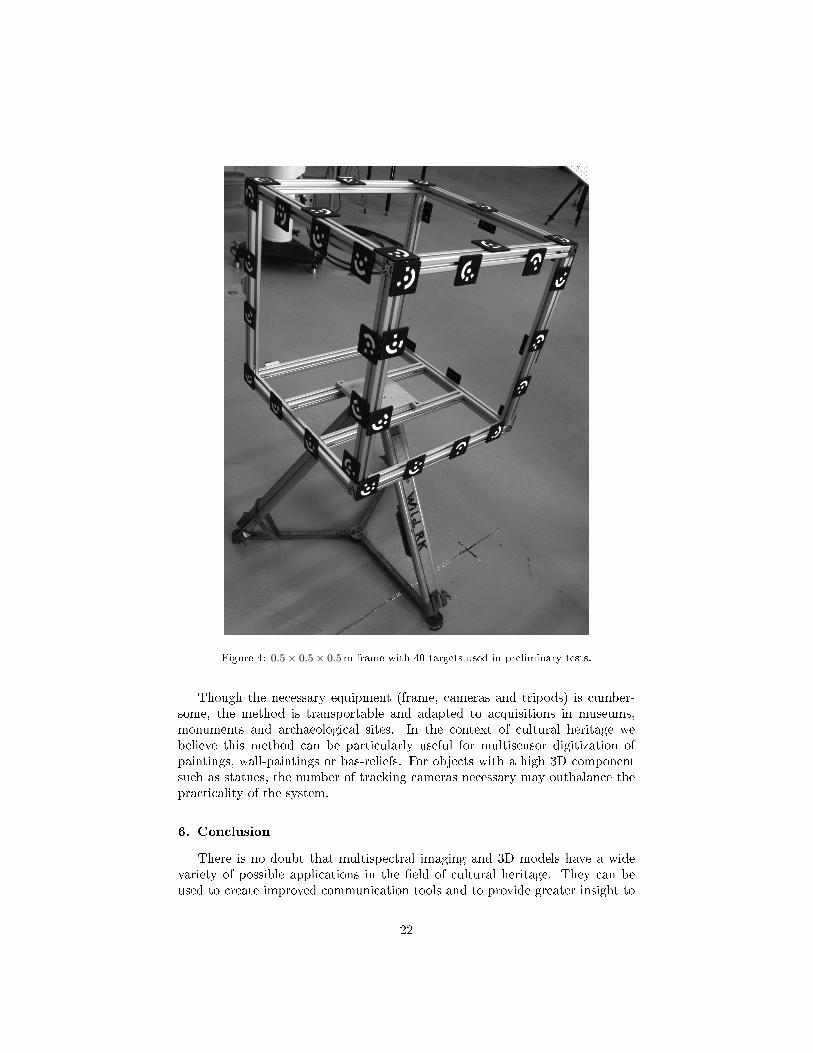
Figure 4: 0.5× 0.5× 0.5m frame with 40 targets used in preliminary tests.
Though the necessary equipment (frame, cameras and tripods) is cumber-some, the method is transportable and adapted to acquisitions in museums,monuments and archaeological sites. In the context of cultural heritage webelieve this method can be particularly useful for multisensor digitization ofpaintings, wall-paintings or bas-reliefs. For objects with a high 3D componentsuch as statues, the number of tracking cameras necessary may outbalance thepracticality of the system.
6. Conclusion
There is no doubt that multispectral imaging and 3D models have a widevariety of possible applications in the �eld of cultural heritage. They can beused to create improved communication tools and to provide greater insight to
22
conservators regarding the history and condition of the object. On the acquisi-tion side, both types of sensors must be improved to capture dark, transparent,shiny materials.
The integration of 3D and multispectral data is a di�cult task. A fewintegrated devices have been developed, but most of these seem too bulky to beused for the in-situ study of cultural heritage. Systems developed speci�callyfor cultural heritage are application-driven and not easily adapted to di�erenttypes of objects. We believe the use of optical tracking for the multi-sensorintegration of data on a 3D model o�ers a good compromise between the requiredmaterials and e�orts, and the achieved precision. This technique fairs especiallywell for the study of mainly two-dimensional objects such as paintings, wall-paintings and bas-reliefs. When analyzing highly three-dimensional objects suchas statues, the use of registration algorithms may be better adapted.
Optical tracking can be used to project the variety of data acquired whenstudying cultural heritage (color images, multispectral acquisitions, infra-redre�ectography data, �uorescence images, etc.) on a single 3D model. Data fromother optical sensors such as polarimetry imaging, thermal imaging, shearogra-phy, etc. can also be integrated on the same model.
As the quantity of data acquired increases, there is a growing need for newdata analysis techniques to help make sense of the data. Segmentation, recog-nition and classi�cation algorithms must now be based on the whole integrateddataset, and not a single aspect (3D or multispectral). Post-processing mustbe developed hand in hand with the conservation community to provide themwith valuable information. New visualization and interaction methods must bedeveloped so that specialists and non-specialists can interact intuitively withthese augmented models. As multi-modal models gain widespread use, there isa great need of standards to share data between di�erent entities.
Acknowledgments
The authors are grateful for the �nancial support provided by the ConseilRégional de Bourgogne (France) and i3mainz, Institute for Spatial Informationand Surveying Technology (Germany).
References
[1] R. S. Berns, The Science of Digitizing Paintings for Color-Accurate ImageArchives: A Review, Journal of Imaging Science and Technology 45 (2001)305�325.
[2] R. S. Berns, L. A. Taplin, M. Nezamabadi, M. Mohammadi, Y. Zhao,Spectral imaging using a commercial color-�lter array digital camera, in:Proceedings of the 14th Triennial ICOM-CC Meeting, volume 2, pp. 743�750.
23

[3] P. Cotte, M. Dupouy, Crisatel High Resolution Multispectral System, in:IS&T's Image Processing, Image Quality, Image Capture Systems Confer-ence, Rochester, NY, USA, pp. 161�165.
[4] A. Mansouri, F. S. Marzani, J. Y. Hardeberg, P. Gouton, Optical cal-ibration of a multispectral imaging system based on interference �lters,Optical Engineering 44 (2005) 027004 1�12.
[5] J. Brauers, N. Schulte, T. Aach, Multispectral �lter-wheel cameras: Geo-metric distortion model and compensation algorithms, IEEE Transactionson Image Processing 17 (2008) 2368�2380.
[6] A. Pelagotti, A. Del Mastio, A. De Rosa, A. Piva, Multispectral imagingof paintings, IEEE Signal Processing Magazine 25 (2008) 27�36.
[7] M. Yamaguchi, H. Haneishi, N. Ohyama, Beyond Red-Green-Blue (RGB):Spectrum-Based Color Imaging Technology, Journal of Imaging Scienceand Technology 52 (2008) 010201.
[8] J. Brauers, T. Aach, Longitudinal aberrations caused by optical �lters andtheir compensation in multispectral imaging, in: 15th IEEE InternationalConference on Image Processing, San Diego, CA, pp. 525�528.
[9] J. Brauers, T. Aach, Modeling and Compensation of Ghosting in Multi-spectral Filter Wheel Cameras, in: IEEE Southwest Symposium on ImageAnalysis and Interpretation, Santa Fe, New Mexico, USA, pp. 85�88.
[10] J. Brauers, S. Helling, T. Aach, Multispectral Image Acquisition withFlash Light Sources, Journal of Imaging Science and Technology 53 (2009)031103.
[11] J. Y. Hardeberg, Acquisition and reproduction of colour images: col-orimetric and multispectra approaches, Ph.D. thesis, École NationaleSupérieure des Télécommunications de Paris, 1999.
[12] J. Y. Hardeberg, F. J. Schmitt, H. Brettel, Multispectral color imagecapture using a liquid crystal tunable �lter, Optical Engineering 41 (2002)2532�2548.
[13] R. S. Berns, Color-Accurate Image Archives Using Spectral Imaging, in:Proceedings of the National Academy of Science - Scienti�c Examinationof Art: Modern Techniques in Conservation And Analysis, pp. 105�119.
[14] G. Novati, P. Pellegri, R. Schettini, An a�ordable multispectral imagingsystem for the digital museum, International Journal on Digital Libraries5 (2005) 167�178.
[15] S. Poger, E. Angelopoulou, Selecting Components for Building Multi-spectral Sensors, in: IEEE Conference on Computer Vision and PatternRecognition, Technical Sketches, Kauai, Hawaii, USA.
24

[16] L. Miao, H. Qi, W. E. Snyder, A generic method for generating multispec-tral �lter arrays, in: IEEE International Conference on Image Processing,volume 5, pp. 3343�3346.
[17] J. Brauers, T. Aach, A Color Filter Array Based Multispectral Camera,in: 12. Workshop Farbbildverarbeitung.
[18] J.-I. Park, M.-H. Lee, M. D. Grossberg, S. K. Nayar, Multispectral Imag-ing Using Multiplexed Illumination, in: IEEE 11th International Confer-ence on Computer Vision, Rio de Janeiro, Brasil, pp. 1�8.
[19] N. L. Everdell, I. B. Styles, E. Claridge, J. C. Hebden, A. S. Calcagni,Multispectral imaging of the ocular fundus using LED illumination, in:Proceedings of SPIE Vol. 7371, Novel Optical Instrumentation for Biomed-ical Applications IV, pp. 73711C 1�6.
[20] M. B. Bouchard, B. R. Chen, S. A. Burgess, E. M. C. Hillman, Ultra-fast multispectral optical imaging of cortical oxygenation, blood �ow, andintracellular calcium dynamics., Optics Express 17 (2009) 15670�15678.
[21] S. Tominaga, N. Tanaka, Spectral image acquisition, analysis, and ren-dering for art paintings, Journal of Electronic Imaging 17 (2008) 043022.
[22] K. J. Zuzak, R. P. Francis, E. F. Wehner, J. Smith, M. Litorja, D. W.Allen, C. Tracy, J. Cadeddu, E. Livingston, DLP Hyperspectral Imagingfor Surgical and Clinical Utility, in: Proc. SPIE, Vol. 7210, EmergingDigital Micromirror Device Based Systems and Applications, pp. 7210061�9.
[23] Y. Schechner, S. Nayar, Generalized mosaicing: wide �eld of view mul-tispectral imaging, IEEE Transactions on Pattern Analysis and MachineIntelligence 24 (2002) 1334�1348.
[24] H. Du, X. Tong, X. Cao, S. Lin, A prism-based system for multispectralvideo acquisition., in: IEEE 12th International Conference on ComputerVision, Kyoto, Japan, pp. 175�182.
[25] R. Kawakami, J. Wright, Y.-W. Tai, Y. Matsushita, M. Ben-Ezra,K. Ikeuchi, High-resolution hyperspectral imaging via matrix factoriza-tion, in: IEEE Conference on Computer Vision and Pattern Recognition,Colorado Springs, USA, pp. 2329 � 2336.
[26] K. Martinez, J. Cupitt, D. Saunders, R. Pillay, Ten Years of Art ImagingResearch, Proceedings of the IEEE 90 (2002) 28�41.
[27] A. Ribés, F. Schmitt, R. Pillay, C. Lahanier, Calibration and spectralreconstruction for cristatel: an art painting multispectral acquisition sys-tem, Journal of Imaging Science and Technology 49 (2005) 563�573.
25
[28] R. S. Berns, L. A. Taplin, P. Urban, Y. Zhao, Spectral color reproductionof paintings, in: Proceedings of the Fourth Europeean Conference onColor in Graphics, Imaging and Vision, Barcelona, Spain, pp. 484�488.
[29] P. Cotte, D. Dupraz, Spectral Imaging of Leonardo Da Vinci's MonaLisa: An Authentic Smile at 1523 dpi with Additional Infrared Data, in:Archiving 2006, Ottawa, Canada, pp. 228�235.
[30] J. K. Delaney, E. Walmsey, B. H. Berrie, C. F. Fletcher, Multispectralimaging of paintings in the infared to detect and map blue pigments, in:Proceedings of the National Academy of Sciences, pp. 120�136.
[31] P. Colantoni, R. Pillay, C. Lahanier, D. Pitzalis, Analysis of multispectralimages of paintings, in: 14th European Signal Processing Conference(EUSIPCO 2006), Florence, Italy.
[32] R. L. Easton Jr., K. T. Knox, W. A. Christens-Barry, Multispectral imag-ing of the Archimedes palimpsest, in: Proceedings of the 32nd AppliedImagery Pattern Recognition Workshop, IEEE, Washington, DC, USA,2003, pp. 111�116.
[33] K. Rapantzikos, C. Balas, Hyperspectral imaging: potential in non-destructive analysis of palimpsests, in: IEEE International Conferenceon Image Processing, volume 2, Genoa, Italy, pp. 618�621.
[34] K. Bloechl, H. Hamlin, R. L. J. Easton, Text recovery from the ultraviolet-�uorescence spectrum for a treatise in the Archimedes palimpsest, in:Proceedings of SPIE Vol. 7531, Computer Vision and Image Analysis ofArt, San Jose, CA, USA, pp. 753108 1�9.
[35] R. S. Berns, Rejuvenating the appearance of cultural heritage using colorand imaging science techniques, in: 10th Congress of the InternationalColour Association, Granada, Spain, pp. 369�374.
[36] P. Cotte, D. Dupraz, Multispectral Photography of the Famous Mona LisaPainting, in: Third European Conference on Color in Graphics, Imagingand Vision, IS& T, Leeds, UK, 2006, pp. 311�317.
[37] F. H. Imai, M. R. Rosen, R. S. Berns, Multi-spectral imaging of van gogh'sself-portrait at the national gallery of art washington d.c., in: IS&T'sImage Processing, Image Quality, Image Capture Systems Conference,Montreal, Quebec, Canada, pp. 185�189.
[38] A. Mansouri, F. S. Marzani, P. Gouton, Development of a Protocol forCCD Calibration: Application to a Multispectral Imaging System, Inter-national Journal of Robotics and Automation 20 (2005) 94�100.
[39] F. H. Imai, R. S. Berns, D.-T. Tzeng, A Comparative Analysis of SpectralRe�ectance Estimated in Various Spaces Using a Trichromatic CameraSystem, Journal of Imaging Science and Technology 44 (2000) 280�287.
26

[40] H. Haneishi, T. Hasegawa, A. Hosoi, Y. Yokoyama, N. Tsumura,Y. Miyake, System Design for Accurately Estimating the Spectral Re-�ectance of Art Paintings, Appllied Optics 39 (2000) 6621�6632.
[41] M. Shi, G. Healey, Using re�ectance models for color scanner calibration,Journal of the Optical Society of America A 19 (2002) 645�656.
[42] E. A. Day, The E�ects of Multi-channel Visible Spectrum Imaging onPerceived Spatial Image Quality and Color Reproduction Accuracy, M.s.thesis, Rochester Institute of Technology, 2003.
[43] F. H. Imai, L. A. Taplin, E. A. Day, Comparative study of spectral re-�ectance estimation based on broad-band imaging systems, Technical Re-port, Rochester Institute of Technology, College of Science, Center forImaging Science, Munsell Color Science Laboratory, Rochester, New York,U.S.A., 2003.
[44] V. Cheung, S. Westland, C. Li, J. Hardeberg, D. Connah, Characteriza-tion of trichromatic color cameras by using a new multispectral imagingtechnique, Journal of the Optical Society of America A 22 (2005) 1231�1240.
[45] Y. Zhao, R. S. Berns, Image-based spectral re�ectance reconstructionusing the matrix R method, Color Research & Application 32 (2007)343�351.
[46] F. H. Imai, R. S. Berns, Spectral estimation using trichromatic digitalcameras, in: Proceedings of the International Symposium on MulispectralImaging and Color Reproduction for Digital Archives, pp. 42�49.
[47] X. Zhang, H. Xu, Reconstructing spectral re�ectance by dividing spectralspace and extending the principal components in principal componentanalysis, Journal of the Optical Society of America A 25 (2008) 371�378.
[48] S. Tominaga, Multichannel vision system for estimating surface and illu-mination functions, Journal of the Optical Society of America A 13 (1996)2163�2173.
[49] H.-L. Shen, P.-Q. Cai, S.-J. Shao, J. H. Xin, Re�ectance reconstructionfor multispectra imaging by adaptive wiener estimation, Optics Express15 (2007) 15545�15554.
[50] F. H. Imai, R. S. Berns, Spectral estimation of artist oil paints usingmulti-�lter trichromatic imaging, in: R. Chung, A. Rodrigues (Eds.),Proceedings of SPIE Vol. 4421, 9th Congress of the International ColorAssociation, Rochester, NY, USA, pp. 504�507.
[51] A. Mansouri, F. S. Marzani, P. Gouton, Neural networks in two cascadealgorithms for spectral re�ectance reconstruction, in: IEEE InternationalConference on Image Processing, volume 2, Genoa, Italy, pp. 718�721.
27

[52] D. R. Connah, J. Y. Hardeberg, Spectral recovery using polynomial mod-els, in: R. Eschbach, G. G. Marcu (Eds.), Proceedings of SPIE Vol. 5667,Color Imaging X: Processing, Hardcopy, and Applications, San Jose, CA,USA, pp. 65�75.
[53] S. Bianco, F. Gasparini, R. Schettini, L. Vanneschi, Polynomial modelingand optimization for colorimetric characterization of scanners, Journal ofElectronic Imaging 17 (2008) 043002.
[54] R. T. Tan, K. Ikeuchi, Separating re�ection components of textured sur-faces using a single image, IEEE Transactions on Pattern Analysis andMachine Intelligence 27 (2005) 178�193.
[55] L. B. Wol�, A polarization-based matrerial classi�cation from spectularre�ection, IEEE Transactions on Pattern Analysis and Machine Intelli-gence 12 (1990) 1059�1071.
[56] S. Lin, H. Y. Shum, Separation of di�use and specular re�ection in colorimages, in: IEEE Conference on Computer Vision and Pattern Recogni-tion, volume 1, Kauai, Hawaii, USA, pp. 341�346.
[57] R. Bajcsy, S. W. Lee, A. Leonardis, Detection of di�use and specularinterface re�ections and inter-re�ections by color image segmentation.,International Journal of Computer Vision 17 (1996) 241�272.
[58] J. Ho, B. V. Funt, M. S. Drew, Separating a color signal into illumina-tion and surface re�ectance components: Theory and applications, IEEETransactions on Pattern Analysis and Machine Intelligence 12 (1990) 966�977.
[59] P.-R. Chang, T.-H. Hsieh, Constrained nonlinear optimization approachesto color-signal separation, IEEE Transactions on Image Processing 4(1995) 81�94.
[60] M. S. Drew, G. D. Finlayson, Analytic solution for separating spectra intoillumination and surface re�ectance components, Journal of the OpticalSociety of America A 24 (2007) 294�303.
[61] Y. Ohta, Y. Hayashi, Recovery of illuminant and surface colors fromimages based on the cie daylight, in: Proceedings of the Third EuropeanConference on Computer Vision, volume 2, pp. 234�246.
[62] S. Tominaga, B. A. Wandell, Standard surface-re�ectance model estima-tion and illuminant estimation, Journal of the Optical Society of AmericaA 6 (1989) 576�584.
[63] L. T. Maloney, B. A. Wandell, Color constancy: a method for recoveringsurface spectral re�ectance, Journal of the Optical Society of America A3 (1986) 29�33.
28

[64] T. Hawkins, J. Cohen, P. Debevec, A Photometric Approach to DigitizingCultural Artifacts, in: Proceedings of the 2001 Conference on VirtualReality, Archeology, and Cultural Heritage, BCM, Glyfada, Greece, 2001,pp. 333�342.
[65] G. Palma, M. Corsini, P. Cignoni, R. Scopigno, M. Mudge, Dynamicshading enhancement for re�ectance transformation imaging, Journal onComputing and Cultural Heritage 3 (2010) 6:1�6:20.
[66] J. Jordan, E. Angelopoulou, Gerbil-a novel software framework for visu-alization and analysis in the multispectral domain, in: R. Koch, A. Kolb,C. Rezk-Salama (Eds.), Vision, Modelling & Visualization, pp. 259�266.
[67] S. J. Kim, F. Zhao, Shaojieand Deng, C.-W. Fu, M. S. Brown, Interac-tive visualization of hyperspectral images of historical documents, IEEETransactions on Visualization and Computer Graphics 16 (2010) 1441�1448.
[68] M. Barni, A. Pelagotti, A. Piva, Image Processing for the Analysis andConservation of Paintings: Opportunities and Challenges, IEEE SignalProcessing Magazine 22 (2005) 141�144.
[69] F. Remondino, S. El-Hakim, A. Gruen, L. Zhang, Turning images into3-D models, IEEE Signal Processing Magazine 25 (2008) 55�64.
[70] S. Agarwal, Y. Furukawa, N. Snavely, I. Simon, S. Seitz, R. Szeliski, Build-ing rome in a day, in: IEEE 12th International Conference on ComputerVision, Kyoto, Japan, pp. 72�79.
[71] Y. Furukawa, J. Ponce, Accurate, dense, and robust multi-view stereop-sis, IEEE Transactions on Pattern Analysis and Machine Intelligence 32(2010) 1362�1376.
[72] M. Pollefeys, L. Van Gool, M. Vergauwen, K. Cornelis, F. Verbiest,J. Toops, 3d recording for archaeological �eldwork, Computer Graph-ics and Applications 23 (2003) 20�27.
[73] G. Pavlidis, A. Koutsoudis, F. Arnaoutoglou, V. Tsioukas, Methods for3D digitization of Cultural Heritage, Journal of Cultural Heritage 8 (2007)93�98.
[74] G. Guidi, F. Remondino, M. Russo, F. Menna, A. Rizzi, 3D Modelingof Large and Complex Site Using Multi-sensor Integration and Multi-resolution Data, in: M. Ashley, S. Hermon, A. Proenca, K. Rodriguez-Echavarria (Eds.), Proceedings of the 9th International Symposium onVirtual Reality, Archeology and Cultural Heritage, pp. 85�92.
[75] R. Seulin, C. Stolz, D. Fo�, G. Millon, F. Nicolier, Three-dimensional toolsfor analysis and conservation of ancient wooden stamps, The ImagingScience Journal 54 (2006) 111�121.
29
[76] C. Rocchini, P. Cignoni, C. Montani, P. Pingi, R. Scopigno, A low cost 3Dscanner based on structured light, Computer Graphics Forum 20 (2001)299�308.
[77] Fraunhofer, Handheld optical 3d-scanner "kolibri cordless",2011. http://www.iof.fraunhofer.de/en/business-fields/
photonic-sensors-and-measuring-systems/3d-messsysteme/
kolibri-cordless-handheld-3d.html Last access september 2012.
[78] P. J. Besl, N. D. McKay, A Method for Registration of 3-D Shapes, IEEETransactions on Pattern Analysis and Machine Intelligence 14 (1992) 239�256.
[79] S. Rusinkiewicz, M. Levoy, E�cient variants of the ICP algorithm, in:Proceedings of the Third International Conference on 3-D Digital Imagingand Modeling, Quebec City, Quebec, Canada, pp. 145�152.
[80] M. Andreetto, N. Brusco, G. M. Cortelazzo, Automatic 3-d modeling oftextured cultural heritage objects, IEEE Transactions on Image Process-ing 13 (2004) 354�369.
[81] A. Guarnieri, G. Guidi, G. Tucci, A. Vettore, Towards automatic modelingfor cultural heritage applications, The International Archives of the Pho-togrammetry, Remote Sensing and Spatial Information Sciences XXXIV(2003) 176�181.
[82] F. Bernardini, H. Rushmeier, The 3D Model Acquisition Pipeline, Com-puter Graphics Forum 21 (2002) 149�172.
[83] M. Levoy, S. Rusinkiewicz, M. Ginzton, J. Ginsberg, K. Pulli, D. Koller,S. Anderson, J. Shade, B. Curless, L. Pereira, J. Davis, D. Fulk, The Dig-ital Michelangelo Project: 3D Scanning of Large Statues, in: Proceedingsof ACM SIGGRAPH, pp. 131�144.
[84] K. Pulli, Multiview registration for large data sets, in: Proceedings of theSecond International Conference on 3-D Digital Imaging and Modeling,IEEE Computer Society, Ottawa, Canada, 1999, pp. 160�168.
[85] M. Callieri, P. Cignoni, F. Ganovelli, G. Impoco, C. Montani, P. Pingi,F. Ponchio, R. Scopigno, Visualization and 3D data processing in theDavid restoration, IEEE computer graphics and applications 24 (2004)16�21.
[86] C. Rocchini, P. Cignoni, C. Montani, P. Pingi, R. Scopigno, R. Fontana,L. Pezzati, M. Cygielman, R. Giachetti, G. Gori, 3D scanning the Minervaof Arezzo, in: ICHIM 2001 Conference Proceedings, volume 2, pp. 265�272.
30
[87] K. Ikeuchi, T. Oishi, J. Takamatsu, R. Sagawa, A. Nakazawa, R. Ku-razume, K. Nishino, M. Kamakura, Y. Okamoto, The Great BuddhaProject: Digitally Archiving, Restoring, and Analyzing Cultural HeritageObjects, International Journal of Computer Vision 75 (2007) 189�208.
[88] F. Bernardini, H. Rushmeier, I. M. Martin, J. Mittleman, G. Taubin,Building a Digital Model of Michelangelo's Florentine Pietà, IEEE Com-puter Graphics and Applications 22 (2002) 59�67.
[89] R. Li, T. Luo, H. Zha, 3D digitization and its Applications in CulturalHeritage, in: Proceedings of the Third International Euro-MediterraneanConference on Digital Heritage, Lemessos, Cyprus, pp. 381�388.
[90] D. Koller, J. Trimble, T. Najbjerg, N. Gelfand, M. Levoy, Fragments ofthe city: Stanford's digital forma urbis romae project, in: Proceedingsof the Third Williams Symposium on Classical Architecture, Journal ofRoman Archaeology Suppl., volume 61, pp. 237�252.
[91] J. Y. Zheng, Z. L. Zhang, N. Abe, Virtual recovery of excavated archae-ological �nds, in: Proceedings of Multimedia Computing and Systems,Austin, TX, USA, pp. 348�357.
[92] M. Levoy, An interactive kiosk for the Tribune del David, 2002. Last accessSeptember 2011.
[93] H. Rushmeier, F. Bernardini, Computing consistent normals and col-ors from photometric data, in: Proceeding of the Second InternationalConference on 3-D Digital Imaging and Modeling, Ottawa, Canada, pp.98�108.
[94] D. Nehab, S. Rusinkiewicz, J. Davis, R. Ramamoorthi, E�ciently com-bining positions and normals for precise 3D geometry, ACM Transactionson Graphics 24 (2005) 536�543.
[95] Z. Lu, Y.-W. Tai, M. Ben-Ezra, M. S. Brown, A framework for ultra highresolution 3d imaging, in: IEEE Conference on Computer Vision andPattern Recognition, San Francisco, CA, USA, pp. 1205�1212.
[96] G. Guidi, B. Frischer, M. Russo, A. Spinetti, L. Carosso, L. L. Micoli,Three-dimensional acquisition of large and detailed cultural heritage ob-jects, Machine Vision and Applications 17 (2006) 349�360.
[97] A. Mansouri, A. Lathuiliere, F. Marzani, Y. Voisin, P. Gouton, Toward a3D Multispectral Scanner: An Application to Multimedia, IEEE Multi-Media 14 (2007) 40�47.
[98] R. Sitnik, G. Mczkowski, J. Krzeslowski, Integrated shape, color, andre�ectivity measurement method for 3D digitization of cultural heritageobjects, in: Proceedings of SPIE Vol. 7526, 3D image Processing andApplications, San Jose, CA, USA, pp. 75260Q 1�10.
31

[99] K. Tonsho, Y. Akao, N. Tsumura, Y. Miyake, Development of goniopho-tometric imaging system for recording re�ectance spectra of 3d objects,in: Proceedings of SPIE Vol. 4663, Color Imaging: Device-IndependentColor, Color Hardcopy, and Applications VII, volume 4663, pp. 370�378.
[100] N. Brusco, G. M. Cortelazzo, S. Capeleto, M. Fedel, A. Paviotti, L. Po-letto, G. Tondello, A System for 3D Modeling Frescoed Historical Build-ings with Multispectral Texture Information, Machine Vision and Appli-cations 17 (2006) 373�393.
[101] C. Lahanier, G. Aitken, R. Pillay, J.-A. Beraldin, F. Blais, L. Borgeat,L. Cournoyer, M. Picard, M. Rioux, J. Taylor, B. Breuckmann, P. Colan-toni, C. de Deyne, Two-dimensional multi-spectral digitization and three-dimensional modelling of easel paintings, in: Proccedings of the 14thTriennal ICOM-CC Meeting, The Hague, Netherlands, pp. 30�42.
[102] J. A. Beraldin, F. Blais, P. Boulanger, L. Cournoyer, J. Domey, S. El-Hakim, G. Godin, M. Rioux, J. Taylor, Real world modelling through highresolution digital 3D imaging of objects and structures, ISPRS Journal ofPhotogrammetry and Remote Sensing 55 (2000) 230�250.
[103] J. Taylor, J.-A. Beraldin, G. Godin, L. Cournoyer, R. Baribeau, F. Blais,M. Rioux, J. Domey, NRC 3D Technology for Museum and HeritageApplications, Journal of Visualization and Computer Animation 14 (2003)121�138.
[104] F. Blais, J. Taylor, J. A. Beraldin, G. Godin, L. Cournoyer, M. Picard,L. Borgeat, L. Dicaire, M. Rioux, C. Lahanier, G. Aitken, Ultra-HighResolution Imaging at 50 µm using a Portable XYZ-RGB Color LaserScanner, in: International Workshop on Recording, Modeling and Visu-alization of Cultural Heritage, Ascona, Switzerland, pp. 101�114.
[105] F. Blais, J. A. Beraldin, Recent developments in 3d multi-modal laserimaging applied to cultural heritage, Machine Vision and Applications 17(2006) 395�409.
[106] F. Blais, J. Taylor, G. Godin, L. Cournoyer, J. A. Beraldin, M. Picard,L. Borgeat, M. Rioux, C. Lahanier, Ultra High-Resolution 3D LaserColor Imaging of Paintings: The Mona Lisa by Leonardo Da Vinci, in:M. Castillejo, P. Moreno (Eds.), 7th International Conference on Lasersin the conservation of Artworks, Madrid, Spain, pp. 435�440.
[107] F. Bernardini, I. Martin, H. Rushmeier, High-quality texture reconstruc-tion from multiple scans, IEEE Transactions on Visualization and Com-puter Graphics 7 (2001) 318�332.
[108] R. Tsai, A versatile camera calibration technique for high-accuracy 3Dmachine vision metrology using o�-the-shelf TV cameras and lenses, IEEEJournal on Robotics and Automation 3 (1987) 323�344.
32

[109] K. Pulli, Surface Reconstruction and Display from Range and Color Data,Ph.D. thesis, University of Washington, 1997.
[110] C. Rocchini, P. Cignoni, C. Montani, R. Scopigno, Acquiring, stitchingand blending di�use appearance attributes on 3D models, The VisualComputer 18 (2002) 186�204.
[111] T. Franken, M. Dellepiane, F. Ganovelli, P. Cignoni, C. Montani, R. Scopi-gno, Minimizing user intervention in registering 2D images to 3D models,The Visual Computer 21 (2005) 619�628.
[112] P. A. Viola, W. M. Wells, Alignment by maximization of mutual infor-mation, International Journal of Computer Vision 24 (1997) 137�154.
[113] F. Maes, A. Collignon, D. Vandermeulen, G. Marchal, P. Suetens, Multi-modality image registration by maximization of mutual information, IEEETransactions on Medical Imaging 16 (1997) 187�98.
[114] F. Remondino, A. Pelagotti, A. Del Mastio, F. Uccheddu, Novel dataregistration techniques for art diagnostics and 3d heritage visualization, in:9th Conference on Optical 3D Measurement Techniques, Vienna, Austria.
[115] G. Palma, M. Corsini, M. Dellepiane, R. Scopigno, Improving 2d-3d reg-istration by mutual information using gradient maps, in: EurographicsItalian Chapter Conference, Genoa, Italy, pp. 89�94.
[116] M. Corsini, M. Dellepiane, F. Ponchio, R. Scopigno, Image-to-GeometryRegistration: a Mutual Information Method exploiting Illumination-related Geometric Properties, Computer Graphics Forum 28 (2009) 1755�1764.
[117] F. H. Raab, E. B. Blood, T. O. Steiner, H. R. Jones, Magnetic positionand orientation tracking system, IEEE Transactions on Aerospace andElectronic Systems 15 (1979) 709�718.
[118] E. Paperno, I. Sasada, E. Leonovich, A new method for magnetic posi-tion and orientation tracking, IEEE Transactions on Magnetics 37 (2001)1938�1940.
[119] J. T. Sherman, J. K. Lubkert, R. S. Popovic, M. R. DiSilvestro, Char-acterization of a novel magnetic tracking system, IEEE Transactions onMagnetics 43 (2007) 2725�2728.
[120] T. Clarke, X. Wang, The control of a robot end-e�ector using photogram-metry, International Archives of Photogrammetry and Remote SensingXXXIII (2000) 137�142.
[121] J. Hefele, C. Brenner, Robot pose correction using photogrammetric track-ing, in: K. G. Harding, J. W. V. Miller, B. G. Batchelor (Eds.), Proceed-ings of SPIE Vol. 4189, Machine Vision and Three-Dimensional ImagingSystems for Inspection and Metrology, Boston, MA, USA, pp. 170�178.
33
[122] J. Hefele, Real-time photogrammetric algorithms for robot calibration,International Archives of Photogrammetry and Remote Sensing XXXIV(2002) 33�38.
[123] H.-G. Maas, Dynamic photogrammetric calibration of industrial robots,in: Proceedings of SPIE Vol. 3174, Videometrics V, San Diego, CA, USA,pp. 106�112.
[124] R. Schütze, C. Raab, F. Boochs, H. Wirth, J. Meier, Optopose - a multi-camera system for fast and precise determination of position and orienta-tion for moving e�ector, in: 9th Conference on Optical 3D MeasurementTechniques, Vienna, Austria.
[125] F. Boochs, R. Schütze, C. Raab, H. Wirth, J. Meier, A �exible multi-camera system for precise tracking of moving e�ectors, in: Robotics andApplications, Cambridge, MA, USA.
[126] Steinbicler, T-scan 3, 2012. http://www.steinbichler.com/products/surface-scanning/3d-digitizing/t-scan-3.html.
[127] Creaform, Metrascan 70 and 120, 2012. http://www.creaform3d.com/en/metrology-solutions/optical-3d-scanner-metrascan.
[128] NDI, Scantrak, 2012. http://www.ndigital.com/industrial/
optotrakproseries-models.php.
[129] Leica, T-scan, 2012. http://metrology.leica-geosystems.com/en/
Leica-T-Scan_1836.htm.
[130] Breuckmann, NaviSCAN � Inspection and Scanning without Lim-its, 2010. http://www.breuckmann.com/en/arts-culture/products/
naviscan.html Last access February 2011.
34