Embed Size (px)
Citation preview
software development
Integrating software modelling and prototyping tools
by LUDWIG SLUSKY
Abstract." Innovative computer-aided software engineering (CASE) tools and new software methodologies have had a significant impact on the software system development cycle. As a result, it is important to assess the variety of systems development methodologies and CASE products, and to construct principles of an integrated framework of methods and tools for rapid system development based on conceptual modelling and prototyping.
This paper discusses CASE tools, prototyping, and an integrated system development approach, based on an evolution of)bur successive phases. conceptualization, logical modelling, prototyping, and migration into a final system. It also classifies CA SE tools into categories and clarifies their relationship within the integrated framework. In addition, the different categories of prototypes are discussed.
Kcvwords. soJtware engineering, software tools, prototyping.
D uring the past few years, there have been major improvements in productivity of the software system development cycle as a result of new
software methodologies and innovative software tech- nology. The impact of software tools is particularly important in applications in which problems can be modelled in a structured manner and are easier to define and to solve with relational logic.
The organization of software development incorpo- rates four major components:
• project management (on the levels of phases-activities- tasks),
• methodology, • tools, • implementation environment 1,2
The integration of these components, particularly methods and tools, presents a challenge that promises to
Information Systems Department, California State University, Los Angeles, 5151 State University Drive, Los Angeles, CA 90032, USA
have a major impact on the entire application develop- ment process.
There is a need to assess the variety of methodologies and software productivity tools for software development. Currently, there are approximately 50 or more different methodologies. New software productivity tools are being produced in greater numbers and diversity.
This paper discusses basic principles of an integrated framework for rapid software development, namely the system development life cycle (SDLC/R Framework) based on existing methods and software tools for model- ling and prototyping.
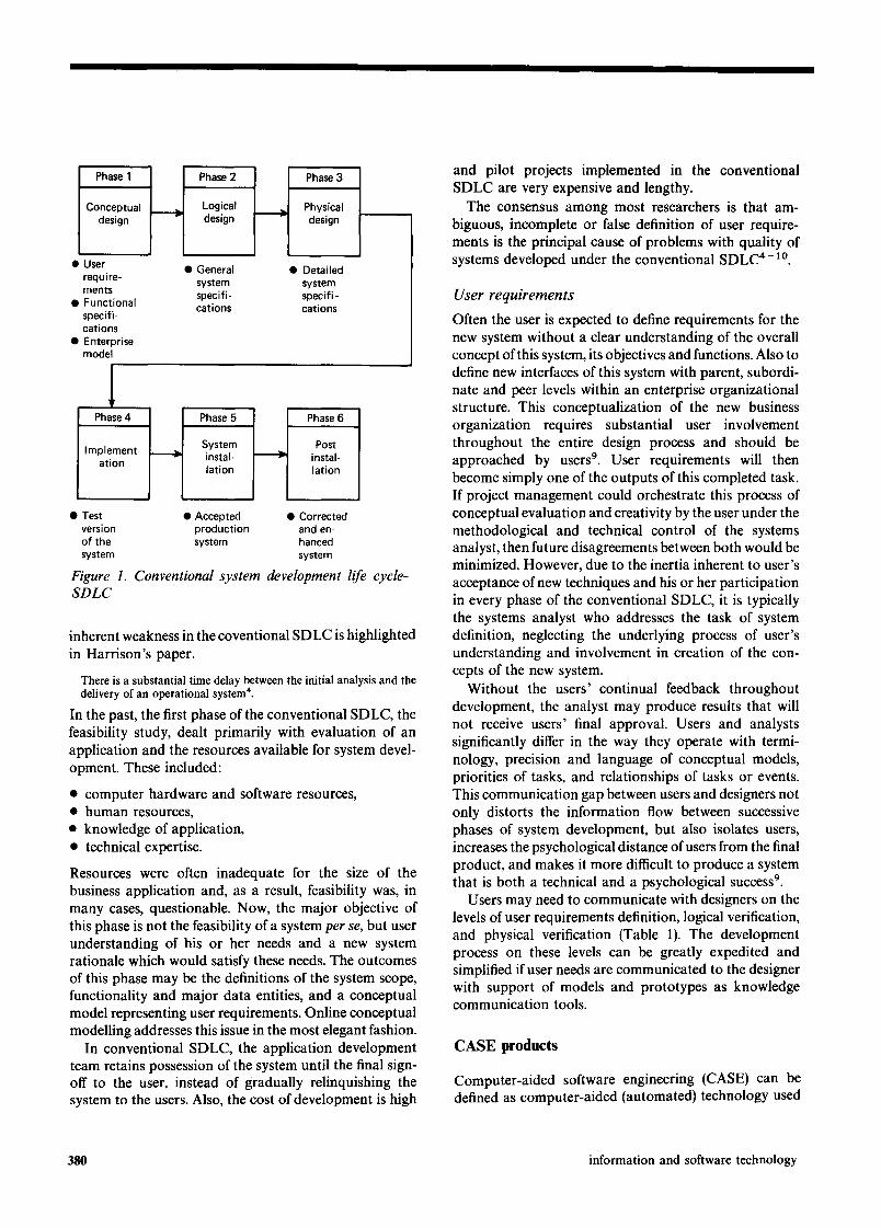
Conventional SDLC
The outline of the conventional SDLC in Figure 1 shows general phases and deliverables of systems development. Actual phases, steps, and deliverables will vary depending on the size of the proposed system, the type of work involved, the approved standards, and the project management.
Although the conventional SDLC has been enhanced by adopting new methods and techniques, its major inherent weaknesses have not been eliminated. For in- stance, it is not receptive to user participation and does not encourage changes 3. Such changes will be made eventually, but they will occur in the form of increased user requests for system maintenance and modification.
User requirements are often vague and poorly de- lineated because of a communication gap between ana- lysts and users. These include different visual represent- ation of user needs and representation of the abstract nature of software by users and designers that frequently do not correspond to each other. Also, different domains of knowledge for both a lack of user's understanding of the methodological and technical reasons behind alterna- tive decisions, and other factors contribute to the com- munication gap between users and analysts. Finally, abstract, intangible components of software design often appear as a series of cryptic notations to users. Another
vol 29 no 7 september 1 9 8 7 0950-5849/87/070379-09503.00 ~:) 1987 Butterworth & Co (Publishers) Ltd. 379
Phase 1
Conceptual design
• User require- ments
• Functional specifi- cations
• Enterprise model
I J I1
Phase 2 Phase 3
Logical Physical design design
• General • Detailed system system specifi- specifi- cations cations
l Phase 4 I Phase 5 I Phase 6
I System I Post Implement- ~ instal- ~ instal- a ,on 1,a ,on-I,at,on
• Test • Accepted • Corrected version production and en- of the system hanced system system
Figure 1. Conventional system development life cycle-- SDLC
inherent weakness in the coventional SDLC is highlighted in Harrison's paper.
There is a substantial time delay between the initial analysis and the delivery of an operational system 4.
In the past, the first phase of the conventional SDLC, the feasibility study, dealt primarily with evaluation of an application and the resources available for system devel- opment. These included:
• computer hardware and software resources, • human resources, • knowledge of application, • technical expertise.
Resources were often inadequate for the size of the business application and, as a result, feasibility was, in many cases, questionable. Now, the major objective of this phase is not the feasibility of a system per se, but user understanding of his or her needs and a new system rationale which would satisfy these needs. The outcomes of this phase may be the definitions of the system scope, functionality and major data entities, and a conceptual model representing user requirements. Online conceptual modelling addresses this issue in the most elegant fashion.
In conventional SDLC, the application development team retains possession of the system until the final sign- off to the user, instead of gradually relinquishing the system to the users. Also, the cost of development is high
and pilot projects implemented in the conventional SDLC are very expensive and lengthy.
The consensus among most researchers is that am- biguous, incomplete or false definition of user require- ments is the principal cause of problems with quality of systems developed under the conventional SDLC 4- lo.
User requirements
Often the user is expected to define requirements for the new system without a clear understanding of the overall concept of this system, its objectives and functions. Also to define new interfaces of this system with parent, subordi- nate and peer levels within an enterprise organizational structure. This conceptualization of the new business organization requires substantial user involvement throughout the entire design process and should be approached by users 9. User requirements will then become simply one of the outputs of this completed task. If project management could orchestrate this process of conceptual evaluation and creativity by the user under the methodological and technical control of the systems analyst, then future disagreements between both would be minimized. However, due to the inertia inherent to user's acceptance of new techniques and his or her participation in every phase of the conventional SDLC, it is typically the systems analyst who addresses the task of system definition, neglecting the underlying process of user's understanding and involvement in creation of the con- cepts of the new system.
Without the users' continual feedback throughout development, the analyst may produce results that will not receive users' final approval. Users and analysts significantly differ in the way they operate with termi- nology, precision and language of conceptual models, priorities of tasks, and relationships of tasks or events. This communication gap between users and designers not only distorts the information flow between successive phases of system development, but also isolates users, increases the psychological distance of users from the final product, and makes it more difficult to produce a system that is both a technical and a psychological success 9.
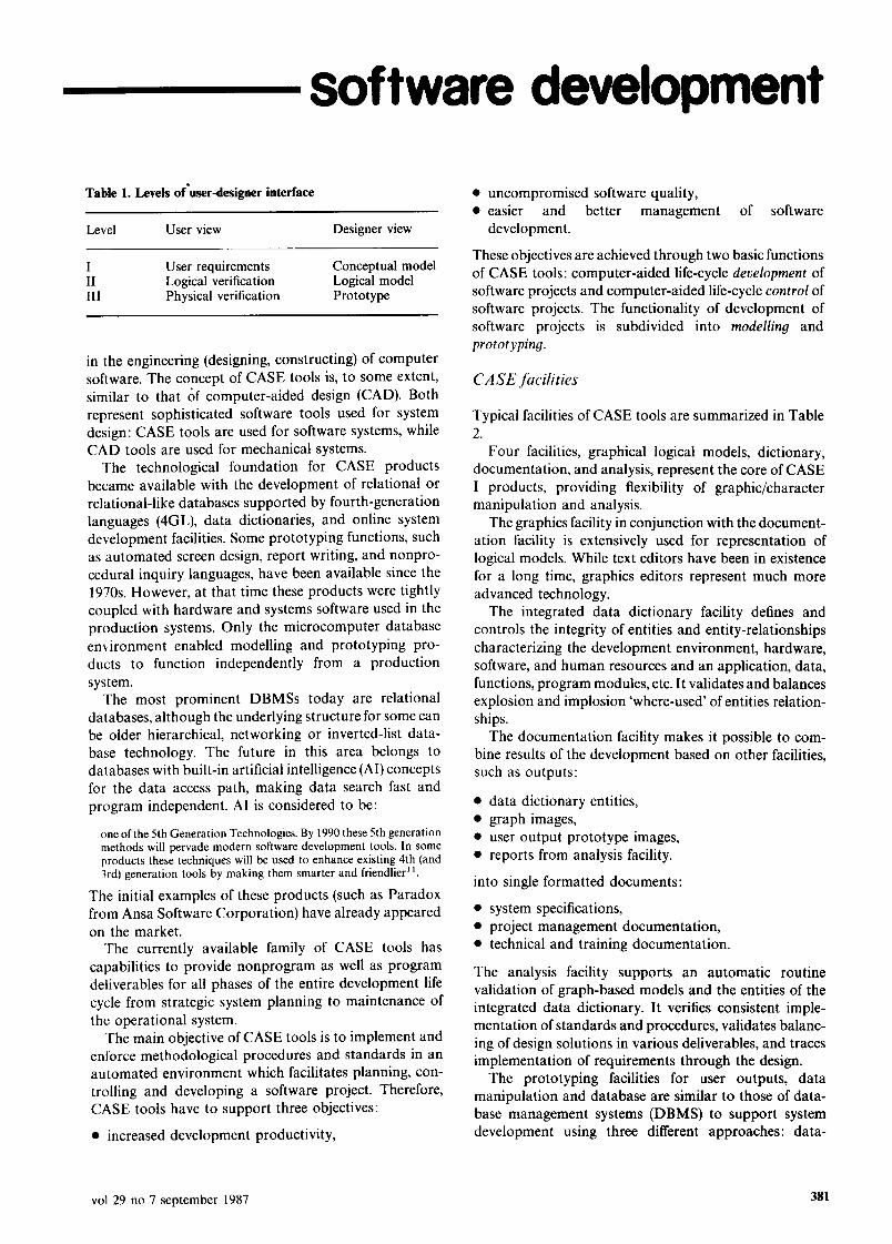
Users may need to communicate with designers on the levels of user requirements definition, logical verification, and physical verification (Table 1). The development process on these levels can be greatly expedited and simplified if user needs are communicated to the designer with support of models and prototypes as knowledge communication tools.
CASE products
Computer-aided software engineering (CASE) can be defined as computer-aided (automated) technology used
380 information and software technology
software development
Table 1. Levels of'user-designer interface
Level User view Designer view
I User requirements Conceptual model II Logical verification Logical model III Physical verification Prototype
in the engineering (designing, constructing) of computer software. The concept of CASE tools is, to some extent, similar to that of computer-aided design (CAD). Both represent sophisticated software tools used for system design: CASE tools are used for software systems, while CAD tools are used for mechanical systems.
The technological foundation for CASE products became available with the development of relational or relational-like databases supported by fourth-generation languages (4GL), data dictionaries, and online system development facilities. Some prototyping functions, such as automated screen design, report writing, and nonpro- cedural inquiry languages, have been available since the 1970s. However, at that time these products were tightly coupled with hardware and systems software used in the production systems. Only the microcomputer database environment enabled modelling and prototyping pro- ducts to function independently from a production system.
The most prominent DBMSs today are relational databases, although the underlying structure for some can be older hierarchical, networking or inverted-list data- base technology. The future in this area belongs to databases with built-in artificial intelligence (AI)concepts for the data access path, making data search fast and program independent. AI is considered to be:
one of the 5th Generation Technologies. By 1990 these 5th generation methods will pervade modern software development tools. In some products these techniques will be used to enhance existing 4th (and 3rd) generation tools by making them smarter and friendlier 11.
The initial examples of these products (such as Paradox from Ansa Software Corporation) have already appeared on the market.
The currently available family of CASE tools has capabilities to provide nonprogram as well as program deliverables for all phases of the entire development life cycle from strategic system planning to maintenance of the operational system.
The main objective of CASE tools is to implement and enforce methodological procedures and standards in an automated environment which facilitates planning, con- trolling and developing a software project. Therefore, CASE tools have to support three objectives:
• increased development productivity,
• uncompromised software quality, • easier and better management of software
development.
These objectives are achieved through two basic functions of CASE tools: computer-aided life-cycle development of software projects and computer-aided life-cycle control of software projects. The functionality of development of software projects is subdivided into modelling and prototyping.
CA SE facilities
Typical facilities of CASE tools are summarized in Table 2.
Four facilities, graphical logical models, dictionary, documentation, and analysis, represent the core of CASE I products, providing flexibility of graphic/character manipulation and analysis.
The graphics facility in conjunction with the document- ation facility is extensively used for representation of logical models. While text editors have been in existence for a long time, graphics editors represent much more advanced technology.
The integrated data dictionary facility defines and controls the integrity of entities and entity-relationships characterizing the development environment, hardware, software, and human resources and an application, data, functions, program modules, etc. It validates and balances explosion and implosion 'where-used' of entities relation- ships.
The documentation facility makes it possible to com- bine results of the development based on other facilities, such as outputs:
• data dictionary entities, • graph images, • user output prototype images, • reports from analysis facility.
into single formatted documents:
• system specifications, • project management documentation, • technical and training documentation.
The analysis facility supports an automatic routine validation of graph-based models and the entities of the integrated data dictionary. It verifies consistent imple- mentation of standards and procedures, validates balanc- ing of design solutions in various deliverables, and traces implementation of requirements through the design.
The prototyping facilities for user outputs, data manipulation and database are similar to those of data- base management systems (DBMS) to support system development using three different approaches: data-
vol 29 no 7 september 1987 381
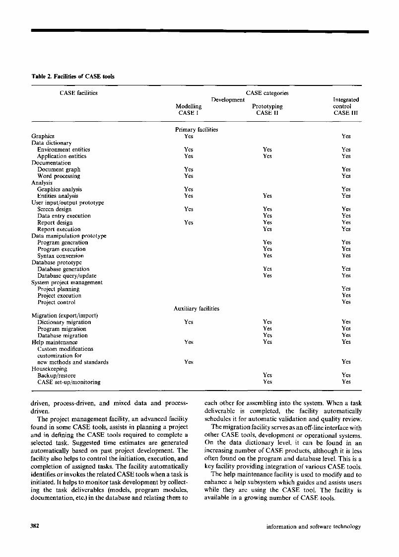
Table 2. Facilities of CASE tools
CASE facilities
Modelling CASE I
Development CASE categories
Integrated Prototyping control
CASE II CASE III
Graphics Data dictionary
Environment entities Application entities
Documentation Document graph Word processing
Analysis Graphics analysis Entities analysis
User input/output prototype Screen design Data entry execution Report design Report execution
Data manipulation prototype Program generation Program execution Syntax conversion
Database prototype Database generation Database query/update
System project management Project planning Project execution Project control
Migration (export/import) Dictionary migration Program migration Database migration
Help maintenance Custom modifications customization for new methods and standards
Housekeeping Backup/restore CASE set-up/monitoring
Primary facilities Yes
Yes Yes
Yes Yes
Yes Yes
Yes
Yes
Auxiliary facilities
Yes
Yes
Yes
Yes
Yes Yes Yes Yes
Yes Yes
Yes Yes Yes
Yes Yes Yes Yes Yes Yes Yes Yes
Yes Yes Yes Yes Yes Yes
Yes Yes Yes Yes
Yes Yes Yes
Yes Yes Yes Yes Yes Yes Yes Yes
Yes
Yes Yes Yes Yes
driven, process-driven, and mixed data and process- driven.
The project management facility, an advanced facility found in some CASE tools, assists in planning a project and in defining the CASE tools required to complete a selected task. Suggested time estimates are generated automatically based on past project development. The facility also helps to control the initiation, execution, and completion of assigned tasks. The facility automatically identifies or invokes the related CASE tools when a task is initiated. It helps to monitor task development by collect- ing the task deliverables (models, program modules, documentation, etc.) in the database and relating them to
each other for assembling into the system. When a task deliverable is completed, the facility automatically schedules it for automatic validation and quality review.
The migration facility serves as an off-line interface with other CASE tools, development or operational systems. On the data dictionary level, it can be found in an increasing number of CASE products, although it is less often found on the program and database level. This is a key facility providing integration of various CASE tools.
The help maintenance facility is used to modify and to enhance a help subsystem which guides and assists users while they are using the CASE tool. The facility is available in a growing number of CASE tools.
382 information and software technology
software development
The custom modifications facility allows the adjust- ment of the functionality and standards of a CASE tool for different methodological requirements.
The housekeeping facility enables a project manager to control functionality and implementation of a CASE tool as a development system.
The functionality of all these facilities may range from manual operations to fully automated procedures. Indiv- idual CASE tools are not necessarily limited, nor does any one tool necessarily incorporate all the facilities of one CASE category.
Earlier CASE tools were implemented on centralized host-based systems. With advances in microcomputer puter technology, there is a tendency to utilize centralized host-based resources for production systems only and shift new software development and CASE technology into a distributed microcomputer-based environment. The benefits of this are faster response time and a greater number of available methods and CASE tools.
Advanced CA SE features
Advanced features include:
• code generation from system specifications or from logical models,
• automated audit trail of all changes, • critical path scheduling with resource availability, • window capability, • automated enforcement of software development.
Rcsearch by Tate and Docker 12 focuses on the develop- ment of a directly-executable prototype from the con- ceptual model in the form of data flow diagrams (DFD). Two components of an executable application model are: the specification part, a conceptual model consisting of DFDs, and the executable part, a prototype automati- cally generated on the specifications of the conceptual model. The model allows an interpretive mode of execut- ion; each specification of the conceptual model is com- piled at execution time. The user can interrupt the execution of the prototype, apply modifications to the conceptual model, and continue execution with modified specifications. The main facilities of this CASE tool are as follows:
First, the active integrated data dictionary. This is where interdependent definitions of DFDs, the processes, and the input-output templates are defined.
Second, the integrated data dictionary processor con- sists of four modules:
• user input/output (the screen/report generation facility),
• data flow manipulation (facility which executes pro- cesses in the lowest levels of DFDs and also provides the storage and retrieval of data flows),
• process scheduler (facility which determines the se- quence of executable processes or navigation rules in the DFD structure),
• process/interpreter (facility which interprets or de- velops an executable module from a data flow language).
Problem statements language/problem statement analy- zer (PSL/PSA), developed by US company Isdos Inc., is a CASE tool that allows writing process specifications in PSL language 13. Specifications are written as a combin- ation of formal statements and text annotation. Such specifications can be produced from DFD, and are then compiled into the executable module. Both the source specifications and the executable module are stored on the database and can be accessed, processed, and analyzed using PSA.
Even more ambitious projects are under consideration to integrate system modelling tools and automated application code generators for procedural specifications.
The direction of new CASE products development and enhancements is as follows.
First, the interface between CASE products. The easiest way to provide this is through fully or partially transform- able data dictionaries, common to all CASE tools.
Second, customization to meet standards or methods of application development that vary from one organization to another. In some CASE products such standards as graphics, naming conventions, symbols, and notations can be modified by a user at his discretion. One example of this is Customizer by Index Technology Corporation to be used with Excelerator, another of their packages.
Third, the direction of new CASE products develop- ment supports new methods of automatic system develop- ment that permit concentration exclusively on software design, leaving implementation of this design to auto- mated code-generating procedures.
Finally, CASE products are expected to be merged with AI technology. This would allow the design of a system on the conceptual level, relegating the following steps of logical and physical design to AI technology. This will revolutionize the complete cycle of application software development. An intermediate solution is expected, a hybrid system combining conventional and AI generated modules 14.
CASE categories
Depending on the objectives of software productivity tools, three CASE categories can be distinguished:
• CASE I - - CASE tools for conceptual/logical modelling.
• CASE II - - CASE tools for prototyping. • CASE III - - CASE tools for project planning, control
vol 29 no 7 september 1987 383
and execution, integrating conceptual modelling and prototyping, are only beginning to evolve in new CASE developments.
Oriented toward conceptual modelling, the first category of CASE tools includes Excelerator, DesignAid, Inform- ation Engineering Workbench, Stradis/Draw. The meth- odological foundation for these products was constructed in numerous theoretical works on structured system analysis and design and on models implementing this foundation, such as data flow diagrams is, structured analysis models 16'17, logical data models, entity- relationship model ~s, structure charts, etc.
The second category of CASE tools is oriented prima- rily toward software prototyping in the DBMS and online environment. Initially, these tools were geared toward mainframes and minicomputers (for example, Pro- fessional Application Creation Environment from Wang and Interactive System Productivity Facility from IBM). Now, these tools are shifting toward a PC-based environ- ment using look-alike mainframe DBMS and online teleprocessing monitors on PC. The list of commercially- available and PC-based prototyping tools includes Micro Focus, Oracle, GoldenGate, TAB, Ideal-Escort, Mantis, Gamma, Natural, and the list is growing.
The third category of CASE tools intends to encompass both system modelling and prototyping, enhanced by a project management facility for planning, control, and execution of the project. CASE III products provide a common user interface to all functions of an application system 19. It is only beginning to emerge in new CASE I and CASE II developments. ISDM, PSL/PSA, and Nastec Corporation's CASE 2000, for example, have been based on this concept. One should expect that CASE III products evolved form CASE II would be more depen- dent on physical constraints of the parent DBMS than new products derived from CASE I.
Two characteristics are essential for the effectiveness of
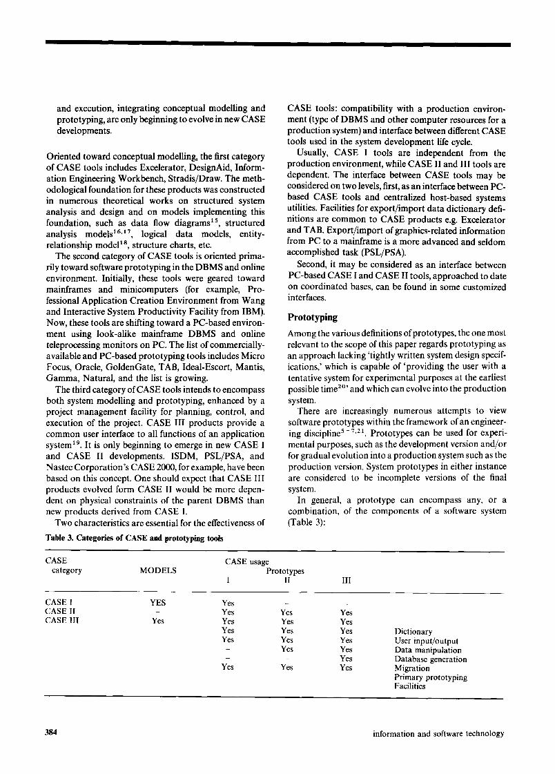
Table 3. Categories of CASE and prototyping tools
CASE tools: compatibility with a production environ- ment (type of DBMS and other computer resources for a production system) and interface between different CASE tools used in the system development life cycle.
Usually, CASE I tools are independent from the production environment, while CASE II and III tools are dependent. The interface between CASE tools may be considered on two levels, first, as an interface between PC- based CASE tools and centralized host-based systems utilities. Facilities for export/import data dictionary defi- nitions are common to CASE products e.g. Excelerator and TAB. Export/import of graphics-related information from PC to a mainframe is a more advanced and seldom accomplished task (PSL/PSA).
Second, it may be considered as an interface between PC-based CASE I and CASE II tools, approached to date on coordinated bases, can be found in some customized interfaces.
Prototyp ing
Among the various definitions of prototypes, the one most relevant to the scope of this paper regards prototyping as an approach lacking 'tightly written system design specif- ications,' which is capable of 'providing the user with a tentative system for experimental purposes at the earliest possible time 2°' and which can evolve into the production system.
There are increasingly numerous attempts to view software prototypes within the framework of an engineer- ing discipline 5- 7.21. Prototypes can be used for experi- mental purposes, such as the development version and/or for gradual evolution into a production system such as the production version. System prototypes in either instance are considered to be incomplete versions of the final system.
In general, a prototype can encompass any, or a combination, of the components of a software system (Table 3):
CASE CASE usage category MODELS Prototypes
I II III
CASE I YES CASE II CASE III Yes
Y e s - -
Yes Yes Yes Yes Yes Yes Yes Yes Yes Yes Yes Yes - Yes Yes - - Yes
Yes Yes Yes
Dictionary User input/output Data manipulation Database generation Migration Primary prototyping Facilities
384 information and software technology
software development
• prototype I, the user input/output prototype (user interface).
• prototype II, the data manipulation prototype (flow of data and processes prototype,
• prototype III, the database prototype.
Consequently, prototyping can require the following CASE facilities:
• online screens/reports design, • data manipulation (programming) language, • data dictionary, • DBMS, • export/import CASE facilities.
Successful prototyping has a number of basic advantages. For example, prototyping increases users' satisfaction. It tion. It is etficient for applications which combine limited complexity with a higher degree of uncertainty. Prototyp- ing also provides the basis for an inexpensive portfolio of reusable system modules and increases user participation. Prototyping reduces the communication gap between analysts and users and can become a decision support facility for analysis of ad hoc requests and 'what if' scenarios. It can also improve planning and hedge against common system development risks. Finally, prototyping is less labour intensive than conventional system development.
However, prototyping is not free of deficiencies since it does not usually provide good system performance. It decreases response time to a frequently unacceptable level and requires tighter control of planning.
Principles of an integrated framework
Tile purpose of an integrated framework is to increase development productivity and to achieve a reliable, quality system by utilizing new software engineering methodologies and technologies. Some researchers define three objectives of a software design method as follows:
• a learning aid assisting the thinking process, • a representation aid, • a visual aid to clarify the abstract nature of software z2.
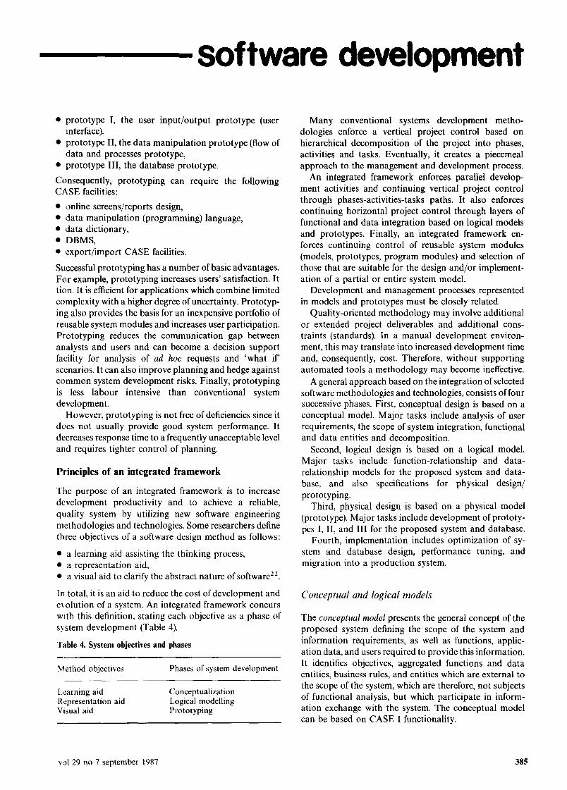
In total, it is an aid to reduce the cost of development and e~ olution of a system. An integrated framework concurs with this definition, stating each objective as a phase of system development (Table 4).
Table 4. System objectives and phases
Method objectives Phases of system development
Learning aid Conceptualization Representation aid Logical modelling Visual aid Prototyping
Many conventional systems development metho- dologies enforce a vertical project control based on hierarchical decomposition of the project into phases, activities and tasks. Eventually, it creates a piecemeal approach to the management and development process.
An integrated framework enforces parallel develop- ment activities and continuing vertical project control through phases-activities-tasks paths. It also enforces continuing horizontal project control through layers of functional and data integration based on logical models and prototypes. Finally, an integrated framework en- forces continuing control of reusable system modules (models, prototypes, program modules) and selection of those that are suitable for the design and/or implement- ation of a partial or entire system model.
Development and management processes represented in models and prototypes must be closely related.
Quality-oriented methodology may involve additional or extended project deliverables and additional cons- traints (standards). In a manual development environ- ment, this may translate into increased development time and, consequently, cost. Therefore, without supporting automated tools a methodology may become ineffective.
A general approach based on the integration of selected software methodologies and technologies, consists of four successive phases. First, conceptual design is based on a conceptual model. Major tasks include analysis of user requirements, the scope of system integration, functional and data entities and decomposition.
Second, logical design is based on a logical model. Major tasks include function-relationship and data- relationship models for the proposed system and data- base, and also specifications for physical design/ prototyping.
Third, physical design is based on a physical model (prototype). Major tasks include development of prototy- pes I, II, and llI for the proposed system and database.
Fourth, implementation includes optimization of sy- stem and database design, performance tuning, and migration into a production system.
Conceptual and logical models
The conceptual model presents the general concept of the proposed system defining the scope of the system and information requirements, as well as functions, applic- ation data, and users required to provide this information. It identifies objectives, aggregated functions and data entities, business rules, and entities which are external to the scope of the system, which are therefore, not subjects of functional analysis, but which participate in inform- ation exchange with the system. The conceptual model can be based on CASE I functionality.
v,al 29 no 7 september 1987 385
The looical model presents the detailed logic of the functions, data, and relationships for the proposed sy- stem. It identifies functions decomposed to the process level to be implemented without further subdivision. Also it identifies data entities decomposed to the data manipul- ation level (data items) without further subdivision. Process navigation rules estabalishing the operational relationships between processes can also be identified and data navigation rules establishing the operational rel- ationships among data structures.
The logical model consists of four main components:
• data dictionary, • logical model of user interface, • logical model of processes, • logical model of data.
The logical model can be based on CASE I functionality, while the physical model can be based on CASE II functionality.
The logical modelling of processes can be separated into four well known steps:
P o - - - > L o - - > L n - - - > Pn
where L = logical model depicting logical characteristics,
P=logica l model depicting logical and physical characteristics,
o = indicator of old or existing system, n = indicator of new or proposed system.
Pn is derived from Ln and depicts characteristics of prototyping resources. Each model is processed twice: top-down as a design step and bottom-up as a verification step. Depending on objectives of modelling, user require- ments, and the size of the system, not all four models must be developed.
Physical model and implementation
The physical model represents the prototype of the detailed logic for the proposed system and includes the prototype of user interface, the prototype of data flow and processes, and the prototype of database structure.
The implementation phase represents implementation of system and database design in a production environment, including conversion, enhancement and export of a prototype into a production system, in addition to optimization and performance tuning.
A system prototype can be used in two different ways:
• as a test version of the system, • as an incomplete version that will be enhanced to the
level of the final version.
More and more frequently, prototypes are used in the latter way. A cost-effective approach to prototyping in an
integrated framework is to utilize software that is compat- ible with, or can easily evolve into, one used in the final system. Prototypes usually have limited functionality and do not provide good performance. Performance require- ments can be implemented on a case-by-case basis or across the application during standard conversion into the final system which must provide adequate performance.
Implementation issues of SDLC/R Framework
The author focused on several issues of rapid system design using SDLC/R Framework, an approach he developed to integrate conceptual modelling, prototyp- ing, planning, and standards, employing Excelerator as a software development tool.
The most important issue is multithreading. Conven- tional SDLC tends to minimize the number of threads in the development process, occasionally becoming a single- thread development methodology. There are several reasons for this tendency.
First, conventional SDLC recognizes the importance of dependencies between activities and, therefore, stresses full accuracy and completion for any successive activity before progressing to another activity. The underlying basis for this is the potential cost associated with the risk that incomplete information will cause wrong decisions during the following activities and that some modific- ations will be needed later. It is easy to see how modifications made in one activity may have a ripple effect through a part or the entire project.
Second, as more activities are performed in parallel, it is more important to coordinate design decisions vertically, between successive activities, and horizontally, between concurrent activities. Without CASE tools, this coordin- ation becomes increasingly difficult.
Third, the manager of the project, by himself, has difficulty in controlling the multithread environment without automated tools that logically and physically integrate the entire project. Consequently, a manager using conventional SDLC will tend to eliminate or postpone various activities to simplify decisions and to make the impact of such decisions more manageable. However, as a firm deadline approaches, the manager may be forced to schedule some activities in parallel. In scheduling terms, a manager applies as late as possible (ALAP) logic to time the development activities under the constraint of a specified project completion date.
To make development rapid, SDLC/R Framework applies as soon as possible (ASAP) path and stresses the objective of making as many as possible activities avail- able for early initiation. That naturally leads to the multithread development environment.
386 information and software technology
software development
With SDLC/R, dependencies between parallel activ- ities can be monitored and controlled with CASE tools (e.g. Excelerator). Essentially, rapid development is achieved not only by higher productivity in performing each individual task, but also because these tasks can be performed in parallel.
The author has concluded, in agreement with other researchers, that three threads can be taken simulta- neously immediately after the conceptualization phase:
• functional modelling, • data modelling, • prototyping.
This becomes possible only if clear and strict top-down structured approach is enforced and if the conceptual phase is finalized in a clear conceptual model defining system interfaces, major functions, corresponding major data subjects, and subsystems.
Paradoxically, at the same time that rapid system development has bridged the traditional communication gap between user and analyst, it may create another: the communication gap between designers working on the same project. Because of the speed of the development process and the multithread approach to produce differ- ent deliverables simultaneously, a much higher level of conceptualization by the team is needed than under conventional SDLC with its emphasis on sequential dependencies of successive activities rather than on dependencies between simultaneously-run activities.
Rapid system development, therefore, implies that practically every member of the development team must rely on the conceptual model of the development to understand the significance and implications of his curr- ent task in a multithread project development. Without this understanding, the SDLC/R environment may ap- pear chaotic.
Because of the emphasis on parallel processing, SDLC/R Framework stresses the importance of cont- inuous system integration which assembles the system from deliverables of parallel activities and from reusable modules maintained in the system development 'library'. Taken as a whole, this reinforces the engineering appro- ach to the system design process.
References
I Hoffnagie, G F and Beregi, W E 'Automating the software development process' IBM Syst. J. Vol 24 No 2 (1985)
2 Wasserman, A I 'Automated tools in the information systems development environment' from Trends in Information Systems North-Holland (1986)
3 Sroka, J M and Rader, M H 'Prototyping increases change of systems acceptance' Data Management (March 1986)
4 Harrison, T Steinbock 'Techniques and issues in rapid prototyping' J. Syst. Management (June 1985)
5 Boar, B 'Application prototyping: a life cycle perspec- tive' J. Syst. Management (February 1986)
6 Burns, R N and Dennis, A R' Selecting the appropriate application development methodology' Data Base (Autumn 1985)
7 Harrison, R 'Prototyping and the systems develop- ment life cycle' J. Sys. Management (August 1985)
8 Pangalos, G 'Information-oriented approach to struc- tured analysis and design' Inf. Age Vol 8 No 1 (January 1986)
9 Segall, M J 'The use of prototyping to aid implement- ation of an on-line system' Syst. Objectives Solutions (August 1984)
10 Smith, P M 'A prototyping case study' J. Inf. Syst. Management (Summer 1985)
I 1 Schussel, G 'DB&4GL' Canadian Data Syst. (Novem- ber 1985)
12 Tate, G and Docker, T W G 'A rapid prototyping system based on data flow principles' A CM SIGSOFT Software Eng. Notes Vol 10 No 2 (April 1985)
13 Birrell, N D and Ould, M A A Practical Handbook for Software Development Cambridge University Press (1985)
14 Kowalski, R 'AI and software engineering' Datam- ation (November 1984)
15 Gane, C and Sarson, T Structured systems analysis: tools and techniques' Prentice-Hall (1979)
16 Ross, D T 'Structured analysis: a language for com- municating ideas' Trans. Software Eng. (January 1977)
17 DeMareo, T Structured Analysis and System Specific- ations Yourdon Press (1979)
18 Chen, P 'The entity-relationship model toward a united view of data' Trans. Database Syst. (March 1976)
19 Case, A Information System Development." Principles of Computer-Aided Software Engineering Prentice- Hall, Englewood Cliffs, NJ USA (1986)
20 Janson, M A and Smith, D L 'Prototyping for systems development: a critical appraisal' MIS Quar- terly (December 1985)
21 Bottom, J, Bernard, A and Anderson, K 'The art of modeling' Datamation (November 1985)
22 Freeman, P 'Software design techniques: current options' Infotech State of the Art Report Series 9 No 6 Systems Design (1981) []
vol 29 no 7 september 1987 387