Embed Size (px)
Citation preview

Integrating Reverse-Electrodialysis Stacks with FlowBatteries for Improved Energy Recovery from SalinityGradients and Energy StorageXiuping Zhu,*[a, b] Taeyoung Kim,[a] Mohammad Rahimi,[c] Christopher A. Gorski,[a] andBruce E. Logan[a]
Introduction
Salinity gradients naturally existing between river water andseawater could provide a large and renewable resource forclean energy production.[1] The global extractable energy fromsuitable river mouths is estimated to be 625 TWh per year,which is equivalent to 3 % of the global electricity consump-tion.[2] Several salinity gradient energy (SGE) technologies havebeen proposed to capture this energy, including pressure-re-tarded osmosis (PRO),[3] reverse electrodialysis (RED),[4] capaci-tive mixing (CapMix),[5] and hydrogel expansion (HEx).[6] Amongthese SGE technologies, RED has the advantage of continuous-ly converting energy into electricity.
A RED stack consists of an anode chamber, a series of mem-brane cells with alternating cation-exchange membranes(CEMs) and anion-exchange membranes (AEMs), and a cathodechamber.[7] If solutions with different salinities flow through
channels separated by CEMs and AEMs, a voltage of approxi-mately 0.1 to 0.2 V is generated across each membrane owingto the ion flux caused by the differences in salt concentra-tions.[1b, 8] Cations are driven from high-concentration (HC) tolow-concentration (LC) channels through CEMs, whereasanions are driven from HC to LC compartments through AEMs.A large number of pairs of CEMs and AEMs can be stacked to-gether to increase the total voltage.[9] At both ends of thestack, electrodes are used to convert the ion flux into an elec-trical current through reduction–oxidation (i.e. , redox) reac-tions at the electrodes, such as water splitting.[10] Reversibleredox reactions (e.g. , [Fe(CN)6]4�/[Fe(CN)6]3� and Fe2+/Fe3 +)that are recycled between the electrodes have been investigat-ed to reduce the electrode overpotentials and, thus, to im-prove the power output.[10b] However, there has been no previ-ous effort to extract energy from these redox couples. In addi-tion, the power densities of RED stacks (typically �1 W m�2-membrane) have been too low for practical applications.[1]
Recently, new types of organic redox-active energy carriershave been developed for use in flow batteries to increase theirpower and to avoid the need for rare and toxic metals such asvanadium and zinc.[11] For example, 2,6-dihydroxyanthraqui-none (2,6-DHAQ, also referred to as DQ) and ferrocyanide[Fe(CN)6
4�, FC] redox couples used by Lin et al.[12] were com-posed entirely of earth-abundant elements that were nontoxic,nonflammable, and safe for use in residential and commercialenvironments. The main advantage of the flow battery isenergy storage, as the liquid charged redox-active solutionscan be stored in external tanks and then pumped into the cellfor electricity generation when needed.[12, 13] However, existingflow battery systems must be charged using electricity, and
Salinity gradient energy can be directly converted into electri-cal power by using reverse electrodialysis (RED) and othertechnologies, but reported power densities have been too lowfor practical applications. Herein, the RED stack performancewas improved by using 2,6-dihydroxyanthraquinone and ferro-cyanide as redox couples. These electrolytes were then used ina flow battery to produce an integrated RED stack and flowbattery (RED-FB) system capable of capturing, storing, and dis-charging salinity gradient energy. Energy captured from theRED stack was discharged in the flow battery at a maximum
power density of 3.0 kW m�2-anode, which was similar to theflow batteries charged by electrical power and could be usedfor practical applications. Salinity gradient energy capturedfrom the RED stack was recovered from the electrolytes aselectricity with 30 % efficiency, and the maximum energy den-sity of the system was 2.4 kWh m�3-anolyte. The combinedRED-FB system overcomes many limitations of previous ap-proaches to capture, store, and use salinity gradient energyfrom natural or engineered sources.
[a] Dr. X. Zhu, Dr. T. Kim, Dr. C. A. Gorski, Dr. B. E. LoganDepartment of Civil and Environmental EngineeringPenn State UniversityUniversity Park, PA 16802 (USA)Fax: (+ 1) 225-578-4945E-mail : [email protected]
[b] Dr. X. ZhuDepartment of Civil and Environmental EngineeringLouisiana State UniversityBaton Rouge, LA 70803 (USA)
[c] M. RahimiDepartment of Chemical EngineeringPenn State UniversityUniversity Park, PA 16802 (USA)
Supporting Information for this article can be found under:http://dx.doi.org/10.1002/cssc.201601220.
ChemSusChem 2017, 10, 1 – 8 � 2017 Wiley-VCH Verlag GmbH & Co. KGaA, Weinheim1 &
These are not the final page numbers! ��These are not the final page numbers! ��
Full PapersDOI: 10.1002/cssc.201601220
they have not previously been used for conversion of otherenergy sources into electricity.
Herein, the electrolytes with FC-DQ redox couples wereused in a RED stack to improve power extraction from naturalsalinity gradients and to provide energy storage. Unlike previ-ous RED approaches for which the electrolytes were recycled,here the redox species were charged for energy storage. Theenergy in the redox couples was subsequently discharged ina flow battery to produce an integrated RED-flow battery(RED-FB) system to efficiently capture, store, and discharge sal-inity gradient energy (Figure 1 and Figure S1, Supporting Infor-mation). In the RED stack, the FC-DQ redox couples reduce theelectrode overpotentials more than NaCl solution. Duringcharging, Fe(CN)6
4� is oxidized to Fe(CN)63� at the anode and
2,6-DHAQ is reduced to 2,6-reDHAQ at the cathode. These twoelectrolyte solutions containing the charged redox couples arethen pumped into the flow battery for discharging, in whichFe(CN)6
3� is reduced to Fe(CN)64� at the cathode and 2,6-
reDHAQ is oxidized to 2,6-DHAQ at the anode. Thus, the REDstack recovers energy from salinity gradients, whereas the flowbattery converts this energy into electrical power. Through theuse of this integrated RED-FB system, salinity gradient energyis captured into solutions with a high energy density and isthen discharged at much higher power densities in the flowbattery than that possible by RED systems.
Results and Discussion
Improved RED performance with redox couples
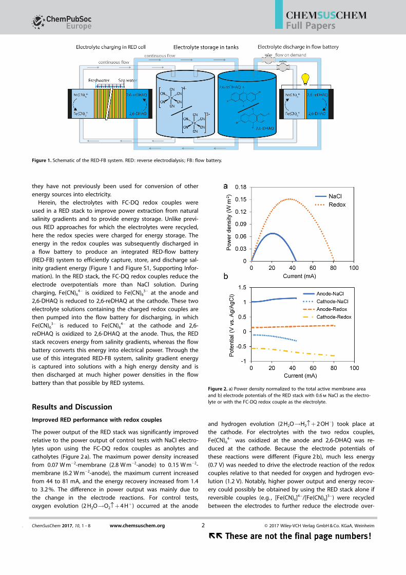
The power output of the RED stack was significantly improvedrelative to the power output of control tests with NaCl electro-lytes upon using the FC-DQ redox couples as anolytes andcatholytes (Figure 2 a). The maximum power density increasedfrom 0.07 W m�2-membrane (2.8 W m�2-anode) to 0.15 W m�2-membrane (6.2 W m�2-anode), the maximum current increasedfrom 44 to 81 mA, and the energy recovery increased from 1.4to 3.2 %. The difference in power output was mainly due tothe change in the electrode reactions. For control tests,oxygen evolution (2 H2O!O2›+ 4 H+) occurred at the anode
and hydrogen evolution (2 H2O!H2›+ 2 OH�) took place atthe cathode. For electrolytes with the two redox couples,Fe(CN)6
4� was oxidized at the anode and 2,6-DHAQ was re-duced at the cathode. Because the electrode potentials ofthese reactions were different (Figure 2 b), much less energy(0.7 V) was needed to drive the electrode reaction of the redoxcouples relative to that needed for oxygen and hydrogen evo-lution (1.2 V). Notably, higher power output and energy recov-ery could possibly be obtained by using the RED stack alone ifreversible couples (e.g. , [Fe(CN)6]4�/[Fe(CN)6]3�) were recycledbetween the electrodes to further reduce the electrode over-
Figure 1. Schematic of the RED-FB system. RED: reverse electrodialysis ; FB: flow battery.
Figure 2. a) Power density normalized to the total active membrane areaand b) electrode potentials of the RED stack with 0.6 m NaCl as the electro-lyte or with the FC-DQ redox couple as the electrolyte.
ChemSusChem 2017, 10, 1 – 8 www.chemsuschem.org � 2017 Wiley-VCH Verlag GmbH & Co. KGaA, Weinheim2&
�� These are not the final page numbers!�� These are not the final page numbers!
Full Papers
potentials.[10b] However, electrolytes with two different redoxcouples (FC and DQ redox couples) were separately flowedthrough the electrodes chambers in the RED-FB system to cap-ture and store the salinity gradient energy in the electrolytes.
Flow battery performance after RED charging at a salinitygradient of 100
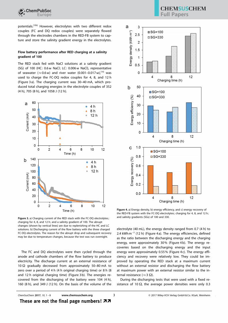
The RED stack fed with NaCl solutions at a salinity gradient(SG) of 100 (HC: 0.6 m NaCl; LC: 0.006 m NaCl), representativeof seawater (�0.6 m) and river water (0.001–0.017 m),[14] wasused to charge the FC-DQ redox couples for 4, 8, and 12 h(Figure 3 a). The charging current was 30–40 mA, which pro-duced total charging energies in the electrolyte couples of 352(4 h), 705 (8 h), and 1058 J (12 h).
The FC and DQ electrolytes were then cycled through theanode and cathode chambers of the flow battery to produceelectricity. The discharge current at an external resistance of10 W gradually decreased from approximately 50–80 mA tozero over a period of 4 h (4 h original charging time) or 8 h (8and 12 h original charging time) (Figure 3 b). The energies re-covered from the discharging of the battery were 104 (4 h),160 (8 h), and 349 J (12 h). On the basis of the volume of the
electrolyte (40 mL), the energy density ranged from 0.7 (4 h) to2.4 kWh m�3 (12 h) (Figure 4 a). The energy efficiencies, definedas the ratio between the discharging energy and the chargingenergy, were approximately 30 % (Figure 4 b). The energy re-coveries based on the discharging energy and the inputenergy were approximately 0.55 % (Figure 4 c). The energy effi-ciency and recovery were relatively low. They could be im-proved by operating the RED stack at a maximum currentwithout an external resistor and discharging the flow batteryat maximum power with an external resistor similar to the in-ternal resistance (�3 W).
During the discharging tests that were used with a fixed re-sistance of 10 W, the average power densities were only 0.3
Figure 3. a) Charging current of the RED stack with the FC-DQ electrolytes;charging for 4, 8, and 12 h; and a salinity gradient of 100. The abruptchanges (shown by vertical lines) are due to replenishing of the HC and LCsolutions. b) Discharging current of the flow battery with the three chargedFC-DQ electrolytes. The reason for the abrupt drop and subsequent recoverymay be due to temperature changes, because the test was run overnight.
Figure 4. a) Energy density, b) energy efficiency, and c) energy recovery ofthe RED-FB system with the FC-DQ electrolytes; charging for 4, 8, and 12 h;and salinity gradients (SGs) of 100 and 330.
ChemSusChem 2017, 10, 1 – 8 www.chemsuschem.org � 2017 Wiley-VCH Verlag GmbH & Co. KGaA, Weinheim3 &
These are not the final page numbers! ��These are not the final page numbers! ��
Full Papers
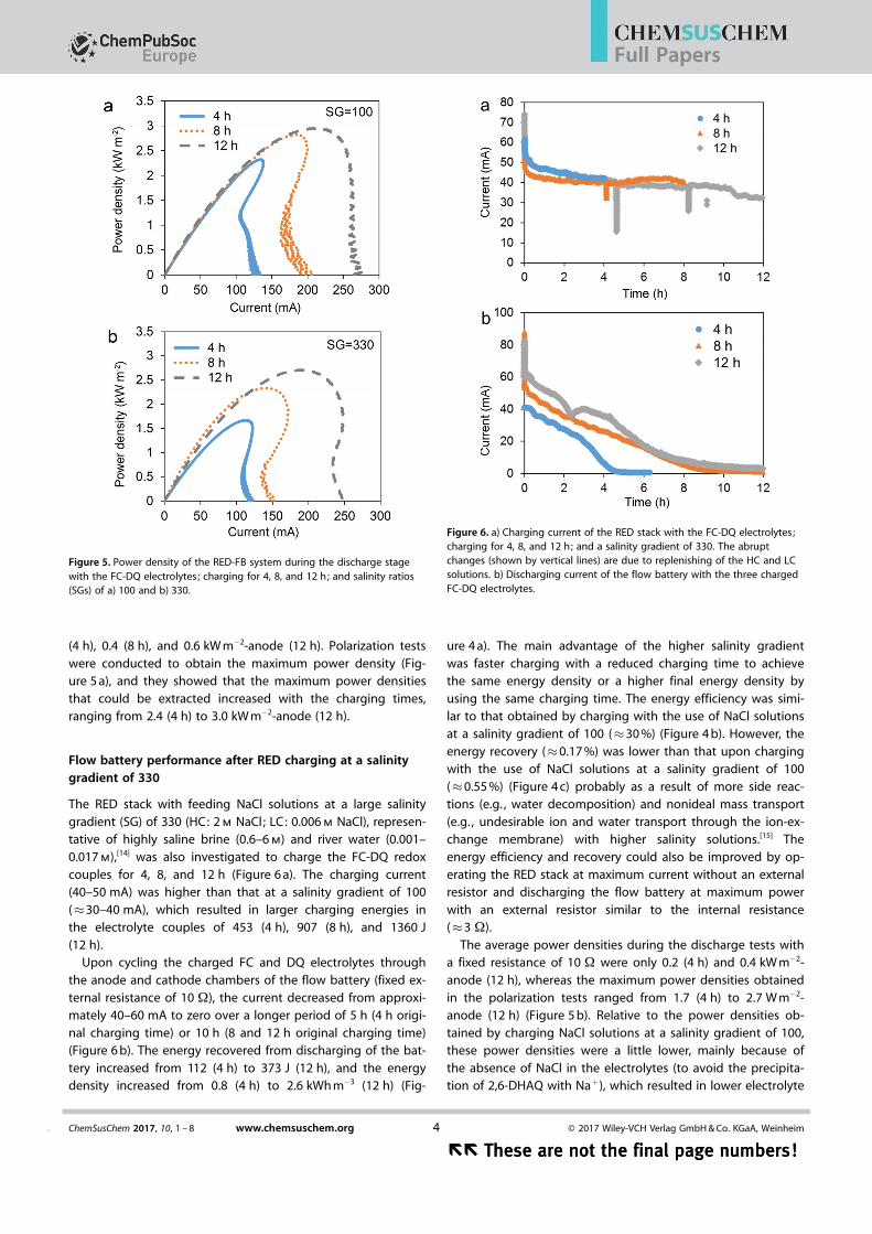
(4 h), 0.4 (8 h), and 0.6 kW m�2-anode (12 h). Polarization testswere conducted to obtain the maximum power density (Fig-ure 5 a), and they showed that the maximum power densitiesthat could be extracted increased with the charging times,ranging from 2.4 (4 h) to 3.0 kW m�2-anode (12 h).
Flow battery performance after RED charging at a salinitygradient of 330
The RED stack with feeding NaCl solutions at a large salinitygradient (SG) of 330 (HC: 2 m NaCl; LC: 0.006 m NaCl), represen-tative of highly saline brine (0.6–6 m) and river water (0.001–0.017 m),[14] was also investigated to charge the FC-DQ redoxcouples for 4, 8, and 12 h (Figure 6 a). The charging current(40–50 mA) was higher than that at a salinity gradient of 100(�30–40 mA), which resulted in larger charging energies inthe electrolyte couples of 453 (4 h), 907 (8 h), and 1360 J(12 h).
Upon cycling the charged FC and DQ electrolytes throughthe anode and cathode chambers of the flow battery (fixed ex-ternal resistance of 10 W), the current decreased from approxi-mately 40–60 mA to zero over a longer period of 5 h (4 h origi-nal charging time) or 10 h (8 and 12 h original charging time)(Figure 6 b). The energy recovered from discharging of the bat-tery increased from 112 (4 h) to 373 J (12 h), and the energydensity increased from 0.8 (4 h) to 2.6 kWh m�3 (12 h) (Fig-
ure 4 a). The main advantage of the higher salinity gradientwas faster charging with a reduced charging time to achievethe same energy density or a higher final energy density byusing the same charging time. The energy efficiency was simi-lar to that obtained by charging with the use of NaCl solutionsat a salinity gradient of 100 (�30 %) (Figure 4 b). However, theenergy recovery (�0.17 %) was lower than that upon chargingwith the use of NaCl solutions at a salinity gradient of 100(�0.55 %) (Figure 4 c) probably as a result of more side reac-tions (e.g. , water decomposition) and nonideal mass transport(e.g. , undesirable ion and water transport through the ion-ex-change membrane) with higher salinity solutions.[15] Theenergy efficiency and recovery could also be improved by op-erating the RED stack at maximum current without an externalresistor and discharging the flow battery at maximum powerwith an external resistor similar to the internal resistance(�3 W).
The average power densities during the discharge tests witha fixed resistance of 10 W were only 0.2 (4 h) and 0.4 kW m�2-anode (12 h), whereas the maximum power densities obtainedin the polarization tests ranged from 1.7 (4 h) to 2.7 W m�2-anode (12 h) (Figure 5 b). Relative to the power densities ob-tained by charging NaCl solutions at a salinity gradient of 100,these power densities were a little lower, mainly because ofthe absence of NaCl in the electrolytes (to avoid the precipita-tion of 2,6-DHAQ with Na+), which resulted in lower electrolyte
Figure 5. Power density of the RED-FB system during the discharge stagewith the FC-DQ electrolytes; charging for 4, 8, and 12 h; and salinity ratios(SGs) of a) 100 and b) 330.
Figure 6. a) Charging current of the RED stack with the FC-DQ electrolytes;charging for 4, 8, and 12 h; and a salinity gradient of 330. The abruptchanges (shown by vertical lines) are due to replenishing of the HC and LCsolutions. b) Discharging current of the flow battery with the three chargedFC-DQ electrolytes.
ChemSusChem 2017, 10, 1 – 8 www.chemsuschem.org � 2017 Wiley-VCH Verlag GmbH & Co. KGaA, Weinheim4&
�� These are not the final page numbers!�� These are not the final page numbers!
Full Papers
conductivity and, therefore, more internal resistance (data forthe NaCl experiments are reported in Figure S2).
RED-FB performance analysis
Previous approaches for extracting energy from salinity gradi-ents have relied upon simultaneous energy extraction andelectricity production.[4a, 5a, 16] In contrast, the RED-FB system de-veloped here allows for energy storage, as the energy extract-ed from the salinity gradients is stored in the FC-DQ redoxcouple solutions, which can then be used for power genera-tion when needed. The power densities were significantly im-proved upon using the flow battery for harvesting electricalpower rather than directly in the RED stack. The maximumpower density of the flow battery reached 3.0 kW m�2-anodeafter charging by the RED stack for 12 h at a salinity gradientratio of 100, which is similar to that of flow batteries chargedby electrical power[11e, 12] and can be used for practical applica-tions. The energy density of the solutions used for power pro-duction was also greatly enhanced. The maximum theoreticalenergy density of the two NaCl solutions with equivalent vol-umes at a salinity gradient ratio of 100 (HC: 0.6 m NaCl; LC:0.006 m NaCl) is 0.5 kWh m�3-LC solution volume on the basisof Equation (6) (see the Experimental Section). Consideringthat the energy recovery of a RED stack is usually much lessthan 100 % (e.g. , 1.4 % here without redox couples), the actualenergy density of NaCl solutions in RED stacks would be ap-proximately 7 Wh m�3, which is only 0.3 % of the actual energydensity of the FC-DQ redox couple solutions produced for usein the flow battery of up to 2.4 kWh m�3 (RED stack chargingfor 12 h, salinity gradient ratio of 100). Thus, through chargingthe redox couples in the RED stack, the salinity gradientenergy was efficiently stored at much greater densities in theredox solutions, which could subsequently be used as needed.
The energy efficiencies of the RED-FB system, which is therecovered electrical energy (discharging energy) relative to thecharging energy, were approximately 30 %. The loss of part ofthe energy resulted from several different processes. First, non-ideal mass transport (e.g. , undesirable ion and water transportthrough the ion-exchange membrane) in the RED stack couldresult in partial energy loss. This could be reduced by usingmore selective membranes.[15] Second, side reactions (oxygenand hydrogen evolution) could have occurred at the anodeand cathode of the RED stacks instead of charging redox cou-ples. This energy loss could be better controlled by adjustingthe salinity gradient, external resistances, and number of cellpairs in the RED stack. Third, part of the energy in the electro-lytes with charged FC-HQ redox couples was remained in theRED stack and was not transferred into the flow battery for dis-charging. This loss should be negligible for greater amounts ofelectrolytes in larger scale systems. Fourth, oxygen could haveleaked into the electrolytes through tubes and fittings, whichwould have directly oxidized 2,6-reDHAQ. This could be avoid-ed with better designs that use less oxygen-permeable fittingsand tubing. Fifth, Na+ ions will be transported into the catho-lyte to balance the charge in the RED stack, which could resultin precipitation of 2,6-DHAQ if the Na+ concentration becomes
too high. This might be resolved by using other catholytes(such as Br2
[11d] and methyl viologen)[11a,b] instead of 2,6-DHAQor by limiting energy storage with a low concentration of 2,6-DHAQ. Alternatively, ammonium bicarbonate rather than NaClsolutions could be used in the RED stack for waste heatenergy recovery.[15b, 17]
The energy recoveries of the RED-FB system, which is theratio between total recovered electrical energy and totalenergy input into the system, were approximately 0.55 (SG =
100) and 0.17 % (SG = 330). This extent of energy recovery isrelatively low, but it could easily be increased by improvingthe configuration and operation conditions, as the RED stackconditions used here were not optimized. For example, previ-ous studies demonstrated that RED energy production couldbe improved by using profiled membranes to reduce internalresistance[18] and the efficiency of energy extraction could beoptimized by adjusting the HC and LC flow rates.[4b, 7b] Withequal volumes of seawater and river water, the energy recov-ery of the RED stacks could reach approximately 83 %.[4a, 19]
Therefore, the energy recovery of the RED-FB system could beimproved to 25 % even with an energy efficiency of 30 %.
Other applications
Thermolytic salts that can be distilled from water at relativelylow temperatures, such as ammonium bicarbonate (AmB), canbe used to create synthetic salinity gradients by waste heat,and as much as approximately 1 TW is estimated to be avail-able from industries in the USA alone.[17b, 20] With AmB, themaximum power of a RED system is approximately 6.3 W m�2-anode (�0.3 W m�2-membrane) and the energy recovery is ap-proximately 2–6 %.[15b, 17a] Thus, the RED-FB system could alsobe used as a method for energy extraction, storage, and gener-ation from waste heat by using AmB.[15b, 17] In addition, otherredox couples with higher energy densities and lower elec-trode overpotentials could be developed for use in the RED-FB, and they might further improve the energy recovery rela-tive to that of the FC-DQ redox couples tested here.
Conclusions
Through integrating a reverse electrodialysis stack with a flowbattery (RED-FB system), salinity gradient energy was harvest-ed in a flow battery with a maximum power density of3.0 kW m�2-anode, which was much higher than that of a REDstack alone (0.07 W m�2-membrane or 2.8 W m�2-anode). Theenergy density was also increased from 7 (RED with NaCl solu-tions) to 2.4 kWh m�3 (flow battery with redox couple solu-tions). This combined energy extraction and generation ap-proach could make the recovery of salinity gradient energymore practical. The salinity gradient energy can be first storedin solutions with redox couples at an energy density muchhigher than NaCl solutions through a RED stack. Later, it canbe used for extensive applications with a high power densitywhen it is needed.
ChemSusChem 2017, 10, 1 – 8 www.chemsuschem.org � 2017 Wiley-VCH Verlag GmbH & Co. KGaA, Weinheim5 &
These are not the final page numbers! ��These are not the final page numbers! ��
Full Papers
Experimental Section
RED-BF system construction and operation
The RED stack was constructed by using a commercially available20-cell-pair electrodialysis stack (PCCell GmbH, ED 64002-020,Heusweiler, Germany) as shown in Figure S1.[4b, 15b] Both electrodeswere titanium mesh coated with platinum and iridium (Ti/Pt-Ir),with a projected area of 64 cm2 (8 cm � 8 cm). Ag/AgCl referenceelectrodes (210 mV vs. a standard hydrogen electrode, SHE) wereinserted into the anode and cathode chambers to record theanode and cathode potentials. The membrane stack was assem-bled with 21 standard CEMs (PC-SK) and 20 standard AEMs (PC-SA)supplied by the manufacturer, each with an active membrane areaof 64 cm2 (8 cm � 8 cm), for a total active membrane area of0.26 m2. The thickness of spacers between the membranes was0.5 mm. High concentration (HC; 0.6 m NaCl or 2 m NaCl) and lowconcentration (LC; 0.006 m NaCl) solutions were separatelypumped through the HC and LC channels of the stack in a single-pass mode at flow rates of 40 mL min�1. The anolyte and catholyte(each 40 mL) were purged with ultrahigh purity argon to ensuredeaeration before all tests and were then recycled through theanode and cathode chambers at flow rates of 100 mL min�1. Forcontrol tests (RED alone) without redox couples, both the anolyteand catholyte were 0.6 m NaCl. For RED-FB tests with redox couplesand a salinity ratio of 100 (HC: 0.6 m NaCl; LC: 0.006 m NaCl), theanolyte was 0.4 m K4Fe(CN)6, 1 m KOH, and 0.6 m NaCl and the cath-olyte was 0.2 m 2,6-DHAQ, 1 m KOH, and 0.6 m NaCl. For RED-FBtests with redox couples and a salinity ratio of 330 (HC: 2 m NaCl;LC: 0.006 m NaCl), the anolyte was 0.4 m K4Fe(CN)6 and 1 m KOHand the catholyte was 0.2 m 2,6-DHAQ and 1 m KOH, without 0.6 m
NaCl to avoid precipitation resulting from the greater amount ofNa+ ion transport into the electrolytes that resulted from the in-creased current and the use of the higher salinity solutions. KOH(1 m) was added in both cases to increase the solubility of 2,6-DHAQ, as it has higher solubility in more alkaline solutions.
The flow battery was constructed by using commercial hardware(Se-Nr 090820010, H-TEC) as shown in Figure S1. Two pieces ofporous carbon paper (2050-1550, Clean Fuel Cell Energy, LLC) witha size of 4 cm � 5 mm were used as the anode and cathode, andthey were pretreated by immersing in a 1:3 v/v mixture of concen-trated nitric acid and sulfuric acid overnight and then rinsing withdeionized water. The two electrodes were pressed onto oppositesides of a cation-exchange membrane (Selemion CMV). Then, twothin Ti plates with 16 2 mm-diameter holes were separately press-ed onto the back of carbon paper electrodes as current collectors,which resulted in a working surface area of 0.5 cm2 for carbonpaper electrodes. Between the two Ti current collectors and end-plates, the anode and cathode chambers were formed by two gas-kets with a thickness of approximately 2 mm. Then, the whole cellwas clamped together by using screw rods and nuts. The solutionswith charged redox couples by RED were recycled through theanode and cathode chambers of the flow battery at a flow rate of100 mL min�1 for discharging tests.
Performance tests
Polarization tests were performed to obtain the power density ofthe RED stack and the flow battery by using a potentiostat (Bio-Logic, VMP3). Cell voltages were decreased from the open-circuitvoltage (OCV) to 0 V versus the cathode potential (short circuit) ata scan rate of 100 mV s�1. Currents were recorded by using EC-LabV10.02 software. The power density (P) of the RED stack or flow
battery was calculated by using Equation (1):
P ¼ UIA
ð1Þ
in which U is the cell voltage, I is the measured current, and A isthe total active membrane area (0.26 m2) for the RED stack, andthe projected anode or cathode surface area for the flow battery(each 0.5 cm2).
During charging of the redox solutions in the RED system, if no ex-ternal resistor was used, the system could be operated at the maxi-mum current, with all the recovered energy used to charge theredox solutions. However, to measure the charging current duringthe tests (Ic = UR/R), an external resistor (R) of 10 W was added be-tween the anode and the cathode of the RED stack, with the volt-age (UR) over the resistor recorded. Therefore, part of the energywas dissipated through the external resistor, which is defined hereas energy lost to the resistor (ER), determined by Equation (2):
ER ¼Z
tc
0URIcdt ð2Þ
in which UR is the cell voltage (i.e. , the voltage over the resistor), Ic
is the charging current, and tc is the charging time. The energythat was used to charge the redox solutions, called the chargingenergy (Ec), was calculated by using Equation (3):
Ec ¼Z
tc
0UcIcdt ð3Þ
in which Uc is the charging voltage (i.e. , the difference of electrodepotentials, � 0.7 V for FC-DQ redox couples), Ic is the charging cur-rent, and tc is the charging time.
After charging in the RED stack, the anolyte and catholyte werepurged with ultrahigh purity argon again and pumped into theflow battery for discharging tests. During the discharging process-es, the anode and cathode of the flow battery were connectedwith an external resistor (R) of 10 W to obtain the cell voltage (Ud).The discharging current was obtained by using Equation (4), andthe discharging energy (Ed) (recovered energy) was calculated fromEquation (5):
Id ¼Ud
Rð4Þ
Ed ¼Z
td
0UdIddt ð5Þ
in which Ud is the discharging cell voltage, Id is the discharging cur-rent, and td is the discharging time. Notably, the FB was dischargedby using an external resistor of 10 W, rather than by using a smallerresistor (�3 W) at which the maximum power could be producedto obtain a stable power output.
Energy calculations
The total energy input to the system (Ein) was estimated by thechange in the free energy for the complete mixing of the HC andLC solutions according to Equation (6):
ChemSusChem 2017, 10, 1 – 8 www.chemsuschem.org � 2017 Wiley-VCH Verlag GmbH & Co. KGaA, Weinheim6&
�� These are not the final page numbers!�� These are not the final page numbers!
Full Papers
E in ¼ RTX
I
ðV HCcini;HCln
aini;HC
ai;Mþ V LCcin
i;LClnain
i;LC
ai;MÞ ð6Þ
in which R (8.314 J mol�1 K�1) is the gas constant, T (298 K) is theabsolute temperature, V (L) is the volume of solutions, c (mol L�1) isthe molar concentration of ionic species i in the solution, and a isthe activity of ionic species i in the solution. The subscripts denotehigh-concentration (HC), low-concentration (LC), and mixed (M)solutions. The energy densities of the NaCl solutions were calculat-ed by normalizing Ein to the equivalent volume of the HC or LC so-lution (1 m3 each). The energy density of solutions with redox cou-ples was obtained by normalizing recovered energy (dischargingenergy) to the volume of anolyte or catholyte (each 40 mL). Theenergy efficiency was defined as the ratio between recoveredenergy (discharging energy) and charging energy. The energy re-covery of the RED stack alone was calculated on the basis of themaximum power output of the RED stack obtained by the polariza-tion test and the energy input per second obtained according toEquation (6). The energy recovery of the RED-FB system was deter-mined as the recovered energy (discharging energy) over the totalenergy input to the system (Ein).
Acknowledgements
This research was supported by the National Science Foundation(NSF) through the award of CBET-1464891.
Keywords: energy conversion · flow batteries · reverseelectrodialysis · salinity gradient · sustainable chemistry
[1] a) B. E. Logan, M. Elimelech, Nature 2012, 488, 313 – 319; b) G. Z. Ramon,B. J. Feinberg, E. M. V. Hoek, Energy Environ. Sci. 2011, 4, 4423 – 4434.
[2] a) G. L. Wick, W. R. Schmitt, Mar. Technol. Soc. J. 1977, 11, 16 – 21; b) J. D.Isaacs, R. J. Seymour, Int. J. Environ. Stud. 1973, 4, 201 – 205; c) O. A. Al-varez-Silva, A. F. Osorio, C. Winter, Renewable Sustainable Energy Rev.2016, 60, 1387 – 1395.
[3] A. Achilli, A. E. Childress, Desalination 2010, 261, 205 – 211.[4] a) J. W. Post, H. V. M. Hamelers, C. J. N. Buisman, Environ. Sci. Technol.
2008, 42, 5785 – 5790; b) X. P. Zhu, W. H. He, B. E. Logan, J. Membr. Sci.2015, 486, 215 – 221.
[5] a) D. Brogioli, Phys. Rev. Lett. 2009, 103, 058501; b) M. C. Hatzell, K. B.Hatzell, B. E. Logan, Environ. Sci. Technol. Lett. 2014, 1, 474 – 478.
[6] X. P. Zhu, W. L. Yang, M. C. Hatzell, B. E. Logan, Environ. Sci. Technol.2014, 48, 7157 – 7163.
[7] a) E. G�ler, R. Elizen, D. A. Vermaas, M. Saakes, K. Nijmeijer, J. Membr. Sci.2013, 446, 266 – 276; b) J. Veerman, M. Saakes, S. J. Metz, G. J. Harmsen,Environ. Sci. Technol. 2010, 44, 9207 – 9212.
[8] D. A. Vermaas, E. Guler, M. Saakes, K. Nijmeijer, Energy Procedia 2012,20, 170 – 184.
[9] J. Veerman, M. Saakes, S. J. Metz, G. J. Harmsen, J. Membr. Sci. 2009,327, 136 – 144.
[10] a) P. Długołecki, A. Gambier, K. Nijmeijer, M. Wessling, Environ. Sci. Tech-nol. 2009, 43, 6888 – 6894; b) J. Veerman, M. Saakes, S. J. Metz, G. J.Harmsen, J. Appl. Electrochem. 2010, 40, 1461 – 1474.
[11] a) T. Janoschka, N. Martin, U. Martin, C. Friebe, S. Morgenstern, H. Hiller,M. D. Hager, U. S. Schubert, Nature 2015, 527, 78 – 81; b) T. B. Liu, X. L.Wei, Z. M. Nie, V. Sprenkle, W. Wang, Adv. Energy Mater. 2016, 6,1501449; c) Q. Chen, L. Eisenach, M. J. Aziz, J. Electrochem. Soc. 2016,163, A5057 – A5063; d) B. Huskinson, M. P. Marshak, C. Suh, S. Er, M. R.Gerhardt, C. J. Galvin, X. D. Chen, A. Aspuru-Guzik, R. G. Gordon, M. J.Aziz, Nature 2014, 505, 195 – 198; e) Q. Chen, M. R. Gerhardt, L. Hartle,M. J. Aziz, J. Electrochem. Soc. 2016, 163, A5010 – A5013.
[12] K. X. Lin, Q. Chen, M. R. Gerhardt, L. C. Tong, S. B. Kim, L. Eisenach, A. W.Valle, D. Hardee, R. G. Gordon, M. J. Aziz, M. P. Marshak, Science 2015,349, 1529 – 1532.
[13] G. L. Soloveichik, Chem. Rev. 2015, 115, 11533 – 11558.[14] A. F. Pillsbury, Sci. Am. 1981, 245, 54.[15] a) A. Daniilidis, D. A. Vermaas, R. Herber, K. Nijmeijer, Renewable Energy
2014, 64, 123 – 131; b) X. P. Zhu, W. H. He, B. E. Logan, J. Membr. Sci.2015, 494, 154 – 160.
[16] F. La Mantia, M. Pasta, H. D. Deshazer, B. E. Logan, Y. Cui, Nano Lett.2011, 11, 1810 – 1813.
[17] a) M. C. Hatzell, I. Ivanov, R. D. Cusick, X. P. Zhu, B. E. Logan, Phys. Chem.Chem. Phys. 2014, 16, 1632 – 1638; b) R. D. Cusick, Y. Kim, B. E. Logan,Science 2012, 335, 1474 – 1477.
[18] a) D. A. Vermaas, M. Saakes, K. Nijmeijer, J. Membr. Sci. 2011, 385, 234 –242; b) D. A. Vermaas, M. Saakes, K. Nijmeijer, J. Membr. Sci. 2014, 453,312 – 319.
[19] N. Y. Yip, D. A. Vermaas, K. Nijmeijer, M. Elimelech, Environ. Sci. Technol.2014, 48, 4925 – 4936.
[20] a) A. P. Straub, N. Y. Yip, S. Lin, J. Lee, M. Elimelech, Nat. Energy 2016, 1,16090; b) X. P. Zhu, M. Rahimi, C. A. Gorski, B. Logan, ChemSusChem2016, 9, 873 – 879.
Manuscript received: September 1, 2016Revised: November 29, 2016
Accepted Article published: December 1, 2016Final Article published: && &&, 0000
ChemSusChem 2017, 10, 1 – 8 www.chemsuschem.org � 2017 Wiley-VCH Verlag GmbH & Co. KGaA, Weinheim7 &
These are not the final page numbers! ��These are not the final page numbers! ��
Full Papers

FULL PAPERS
X. Zhu,* T. Kim, M. Rahimi, C. A. Gorski,B. E. Logan
&& –&&
Integrating Reverse-ElectrodialysisStacks with Flow Batteries forImproved Energy Recovery fromSalinity Gradients and Energy Storage
Salinity gradient energy recovery: Theenvironmentally friendly 2,6-dihydrox-yanthraquinone (2,6-DHAQ) and ferro-cyanide redox couples are used to inte-grate reverse electrodialysis stacks andflow batteries, called RED-FB systems,for the efficient capture, storage, anddischarge of salinity gradient energy.The maximum power density reaches3.0 kW m�2-anode and the energy densi-ty is 2.4 kWh m�3-anolyte, with anenergy efficiency of 30 %.
ChemSusChem 2017, 10, 1 – 8 www.chemsuschem.org � 2017 Wiley-VCH Verlag GmbH & Co. KGaA, Weinheim8&
�� These are not the final page numbers!�� These are not the final page numbers!


![Performance of the first Reverse Electrodialysis pilot ......electrodialysis can be suitable for different applications, e.g. for power production from natural salinity gradients [3–9],](https://img.pdfslide.us/doc/110x75/5fe0883e71394432a7504fde/performance-of-the-first-reverse-electrodialysis-pilot-electrodialysis-can.jpg)