Embed Size (px)
Citation preview
D.A. Hardy et al., Int. J. Sus. Dev. Plann. Vol. 10, No. 6 (2015) 863–879
© 2015 WIT Press, www.witpress.comISSN: 1743-7601 (paper format), ISSN: 1743-761X (online), http://www.witpress.com/journalsDOI: 10.2495/SDP-V10-N6-863-879
INTEGRATING PHOTOVOLTAIC CELLS INTO DECORATIVE ARCHITECTURAL GLASS USING TRADITONAL GLASS-
PAINTING TECHNIQUES AND FLUORESCENT DYES
D.A. HARDY1, S.C. ROAF2 & B.S. RICHARDS3,4
1School of Engineering and Physical Sciences, Heriot-Watt University, United Kingdom.2School of Energy, Geoscience, Infrastructure and Society, Heriot-Watt University, United Kingdom.
3Institute of Microstructure Technology, Karlsruhe Institute of Technology, Germany. 4Light Technology Institute, Karlsruhe Institute of Technology, Germany.
ABSTRACTPhotovoltaic (PV) cells can be integrated into decorative glass, providing a showcase for this renewable technology, whilst assisting in the creation of sustainable architecture through generation of electricity from the building surface. However, traditional, opaque, square, crystalline-silicon solar cells contrast strongly with their surroundings when incorporated into translucent, coloured glazing. Methods of blending PV cells into their surroundings were developed, using traditional glass painting techniques. A design was created in which opaque paint was applied to the areas of glass around underlying PV cells. Translucent, platinum paint was used on the glass behind the PV cells. This covered the grey cell backs whilst reflecting light and movement. The platinum paint was shown to cause a slight increase in power produced by PV cells placed above it. To add colour, very small amounts of Lumogen F dye (BASF) were incorporated into a silicone encapsulant (Dow Corning, Sylgard 184), which was then used to hold PV cells in place between sheets of painted glass. Lumogen dyes selectively absorb and emit light, giving a good balance between colour addition and electricity production from underlying PV cells. When making sufficient quantities of dyed encapsulant for a 600 ? 450 mm test piece, the brightness of the dye colours faded and fluorescence decreased, although some colour was retained. Improvement of the method, including testing of alternative encapsulant materials, is required, to ensure that the dyes continue to fluoresce within the encapsulant. In contrast, the methods of adding opacity variation to glass, through the use of glass painting, are straightforward to develop for use in a wide vari-ety of PV installations. Improvement of these methods opens up a wide variety of architectural glass design opportunities with integrated PV, providing an example of one new medium to make eco-architecture more aesthetically pleasing, whilst generating electricity.Keywords: architectural glass, encapsulant, fluorescent organic dye, glass paint, lumogen dye, photovoltaics, reflective surface, solar, sustainable architecture, Sylgard 184.
1 INTRODUCTIONThere is a pressing need to make both new and re-furbished buildings that are better suited to the exigencies of the twenty-first century, including being able to mitigate and adapt for climate change through the development of renewable energy systems that are able to power buildings, to substitute for the increasingly scarce, unsustainable and unaffordable fossil fuel energy supply systems [1,2]. Photovoltaics (PV) is the best-suited renewable energy technology for integration onto buildings and into cities, and is a key component of the design palette adopted internationally in the emerging new generation of low carbon and net-zero-energy buildings [3]. PV does have an image problem, including difficulties with the aesthetics of PV within clear glazing schemes. PV now needs to be demonstrated to be an attractive and fashionable proposition for architects and building owners to contend in the very competitive market for building envelope materials [4]. The majority of standard PV modules contain PV cells made from blue or black squares of crystalline silicon (c-Si) [5], which offer the best combination of efficiency, durability and price [6] but can be seen to be rather dour in appearance. PV can be integrated in any position on a building envelope that is not shaded: roofs and
864 D.A. Hardy et al., Int. J. Sus. Dev. Plann. Vol. 10, No. 6 (2015)
facades are the most common. It also has the attractive potential to be able to generate the energy needed to power the building energy demands.
PV cells can also be incorporated into glazing in a relatively easy retrofit operation, so offering an interesting and energy-positive architectural aesthetic for many different new and existing build-ings [7]. Decorative architectural glass designs can be used to alter light levels and colours within a building [8], to generate energy and to enhance architecture artistically. Visible exhibition of PV features can promote the green credentials of a building and its owners, occupiers and designers, as well as generating increasingly cost-efficient electricity. Current PV module rectilinear production and assembly systems constrain artists working with architectural glass into working with the con-trast between geometric PV and translucent, coloured or patterned areas of glazing (see example in Fig. 1a). Variety could be achieved if PV cells could be blended into a wider range of architectural glass designs, including curvilinear schemes. This article explores the ways of softening both the sharpness of rectilinear shapes and the strong contrasts between opaque and light-transmitting areas of glazing.
1.1 Colouring PV
Colour is an important feature of many decorative architectural glass designs [9], and work to improve variety in PV has included addition of colour by methods such as altering the thickness of the anti-reflection coating on the surface of c-Si PV cells [10] (Fig. 1b). This reduces the efficiency of the PV cells but can be useful in architecture where the PV cell surfaces are to be on view. In decorative glazing, colour transmitted to the interior of a building, through translucent materials, can be important. The colour of the outer surface of PV cells is not visible in a building interior, so colouring the PV cell surface is not an important aspect of many architectural glass designs. Colour is much more visible when applied to translucent areas of glazing. Coloured, light-transmitting PV
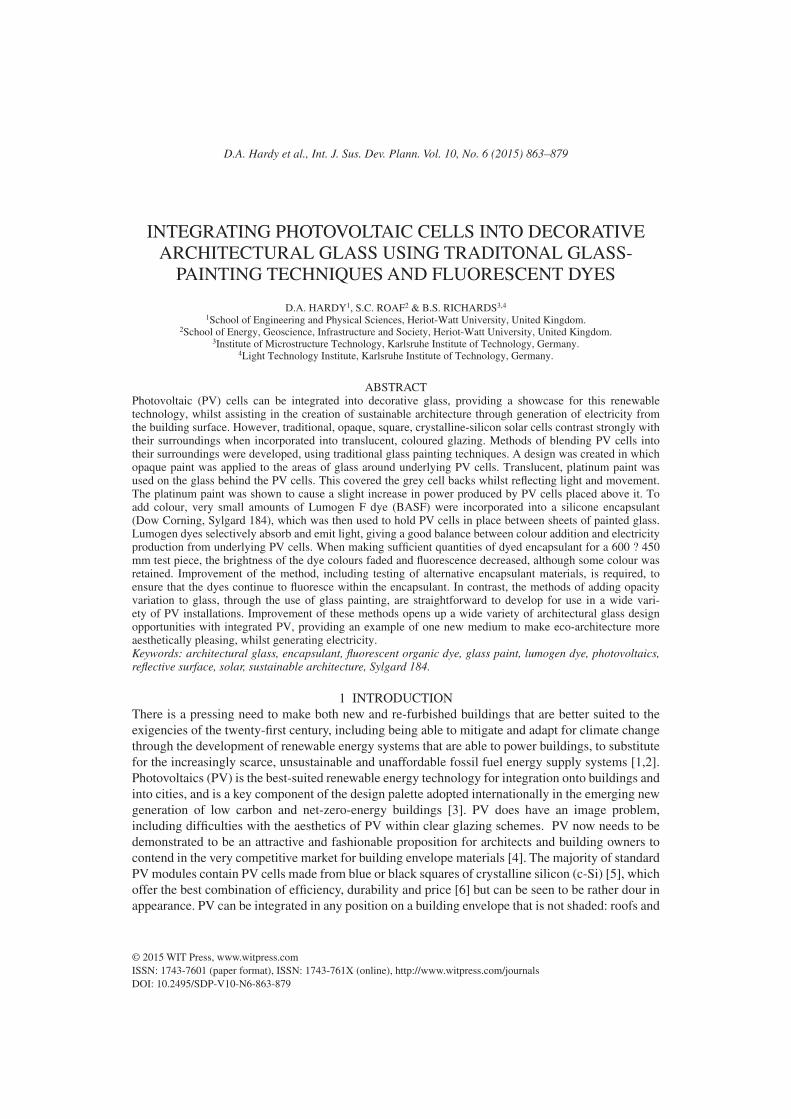
Figure 1: Left: Opaque, square and broken PV cells combined with coloured glass and engraving in a light-transmitting, decorative glass test piece (made by Sigrid Blekastad, Norway). Right: Triangular module, made up from PV cells that have been coloured by varying the thickness of the anti-reflection coating (published with permission from Solar Capture Technologies, UK).
D.A. Hardy et al., Int. J. Sus. Dev. Plann. Vol. 10, No. 6 (2015) 865
products are commercially available [11]. These contain darker strips of thin-film PV material, or strings of c-Si PV cells, contained within translucent, coloured glazing. They, thus, exhibit strong contrasts between dark areas of PV, that absorb the light, and areas of glazing that allow the light to pass through. Many distinctive PV installations are in light-transmitting applications [12], where the contrast between opaque areas of PV and surrounding areas of light-transmitting glazing is key features, as shown in the test piece in Fig. 1a. Colour is noticeable only in the spaces between the PV cells. A more universal application of colour would be preferable.
A variety of architectural glass artworks have been created, using c-Si PV [13,14]. Colour, letter-ing and other artistic forms have been introduced into novel module designs, from Jochem Poensgen’s minimalist use of a few PV cells and some colour [15], to use of colour and text in conjunction with PV cells, in Lynn Goodpasture’s PV windows in Pearl Avenue Branch Library, San José, CA [16], and Sarah Hall’s PV designs, such as True North/Lux Nova, at Regent College, University of British Columbia [17]. All these examples explore the strong contrasts between the opaque, square PV cell shapes and other aspects of the designs. They also contain straight strings of PV cells in rectilinear groupings. A development of this work is to produce light-transmitting PV modules, with the PV cells blended into curvilinear designs.
2 AIMThe aim of the work described here was to blend the stark opacity of square PV cells into a curvilinear design, in a light-transmitting piece of architectural glass. The secondary aim was to add colour to the design, whilst maintaining adequate PV efficiency. Techniques and materials were chosen so that the work could be carried out in a glass studio to ensure that the methodologies were applicable to architectural glass artists. The only exception was the use of a wafer-dicing saw to cut PV cells into small pieces. This meant that small-scale test pieces could be made up. It would be possible to scale up the designs, using full-size, c-Si PV cells, with no cell cutting required.
3 THEORY
3.1 Use of glass-painting techniques
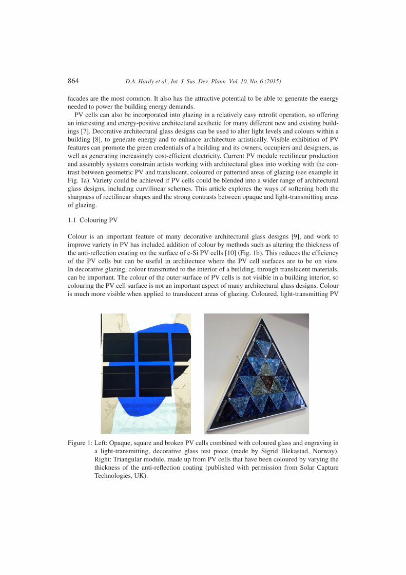
Opaque glass paints are traditionally used to create variation in light transmission in stained and decorative, architectural glass [8]. Glass painting was chosen due to the ease with which a range of test pieces could be made up quickly in a studio setting. Figure 2 shows a painted piece of glass, with a clear, square area, which is placed over a crystalline-silicon PV cell, on a light box. There is a gradation from the opaque PV cell and darker areas of paint to semi-translucent areas. This softens the transition from opaque PV cell edge to the surrounding areas of clear glass.
3.2 Use of fluorescent dyes in silicone PV encapsulant
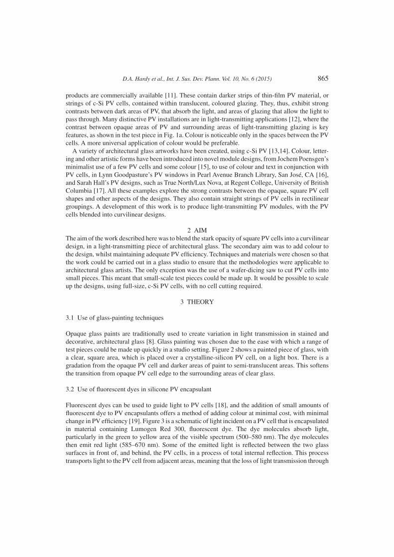
Fluorescent dyes can be used to guide light to PV cells [18], and the addition of small amounts of fluorescent dye to PV encapsulants offers a method of adding colour at minimal cost, with minimal change in PV efficiency [19]. Figure 3 is a schematic of light incident on a PV cell that is encapsulated in material containing Lumogen Red 300, fluorescent dye. The dye molecules absorb light, particularly in the green to yellow area of the visible spectrum (500–580 nm). The dye molecules then emit red light (585–670 nm). Some of the emitted light is reflected between the two glass surfaces in front of, and behind, the PV cells, in a process of total internal reflection. This process transports light to the PV cell from adjacent areas, meaning that the loss of light transmission through
866 D.A. Hardy et al., Int. J. Sus. Dev. Plann. Vol. 10, No. 6 (2015)
Figure 2: The use of glass paint to create opacity variation on a piece of glass placed over a PV cell.
Figure 3: Schematic of light being absorbed by a Lumogen Red 300, fluorescent dye molecule; emitted at a longer wavelength; then moving through the encapsulant material, until it reaches the surface of a PV cell.
D.A. Hardy et al., Int. J. Sus. Dev. Plann. Vol. 10, No. 6 (2015) 867
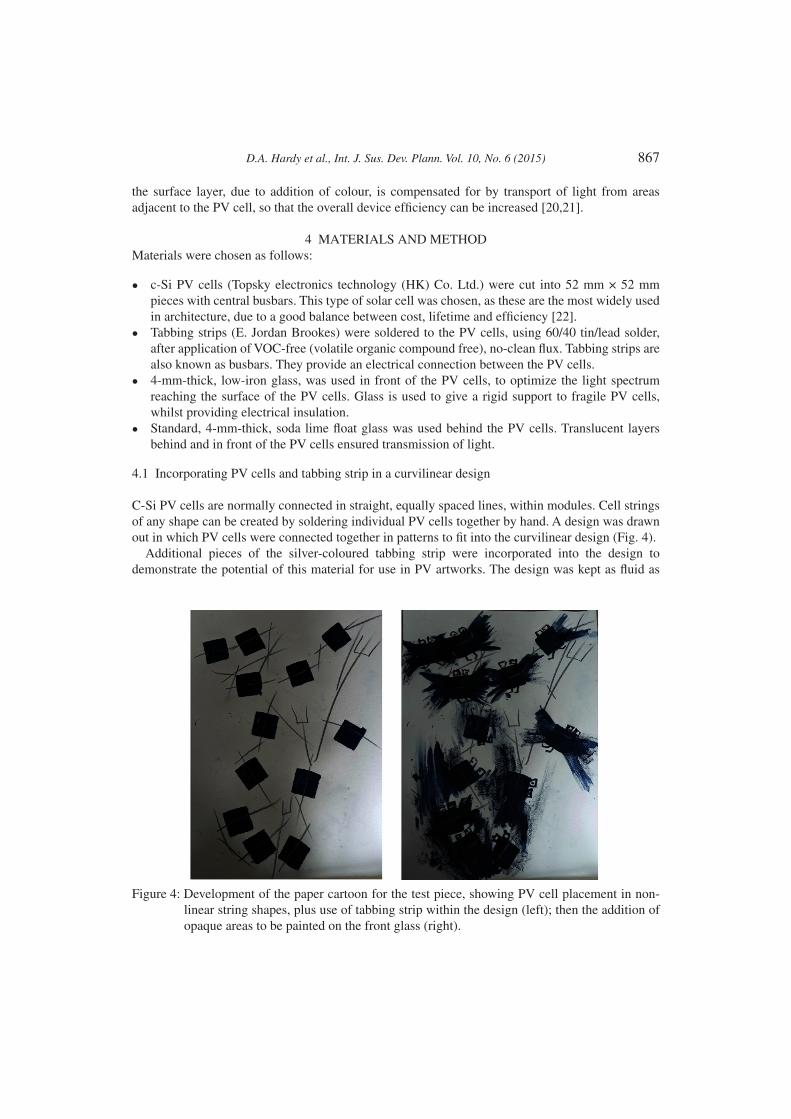
Figure 4: Development of the paper cartoon for the test piece, showing PV cell placement in non-linear string shapes, plus use of tabbing strip within the design (left); then the addition of opaque areas to be painted on the front glass (right).
the surface layer, due to addition of colour, is compensated for by transport of light from areas adjacent to the PV cell, so that the overall device efficiency can be increased [20,21].
4 MATERIALS AND METHODMaterials were chosen as follows:
• c-Si PV cells (Topsky electronics technology (HK) Co. Ltd.) were cut into 52 mm × 52 mm pieces with central busbars. This type of solar cell was chosen, as these are the most widely used in architecture, due to a good balance between cost, lifetime and efficiency [22].
• Tabbing strips (E. Jordan Brookes) were soldered to the PV cells, using 60/40 tin/lead solder, after application of VOC-free (volatile organic compound free), no-clean flux. Tabbing strips are also known as busbars. They provide an electrical connection between the PV cells.
• 4-mm-thick, low-iron glass, was used in front of the PV cells, to optimize the light spectrum reaching the surface of the PV cells. Glass is used to give a rigid support to fragile PV cells, whilst providing electrical insulation.
• Standard, 4-mm-thick, soda lime float glass was used behind the PV cells. Translucent layers behind and in front of the PV cells ensured transmission of light.
4.1 Incorporating PV cells and tabbing strip in a curvilinear design
C-Si PV cells are normally connected in straight, equally spaced lines, within modules. Cell strings of any shape can be created by soldering individual PV cells together by hand. A design was drawn out in which PV cells were connected together in patterns to fit into the curvilinear design (Fig. 4).
Additional pieces of the silver-coloured tabbing strip were incorporated into the design to demonstrate the potential of this material for use in PV artworks. The design was kept as fluid as
868 D.A. Hardy et al., Int. J. Sus. Dev. Plann. Vol. 10, No. 6 (2015)
possible, surrounding each PV cell shape with an area of paint; softening the transition from opaque cell edge to clear glass. This meant that the square cell shapes were disguised for distance viewing. The addition of small, rectangular shapes mimicked the rectilinear PV cell shapes, symbolizing eyes in the design; adding detail and humour. These were designed to be visible on closer viewing, when the PV cell shapes would also be noticeable within the painted design.
4.2 Paints and firing schedules
Ceramic glass paints were used to create an area of pattern around each PV cell. The rectilinear shapes of the PV cells were disguised by applying paint to the glass that was to be placed in front of them. Masking was used to leave square areas clear of paint, so that PV cells placed underneath would be exposed to light. Masking was also used to add small the small, rectangular shapes that acted as eyes in the design. Tests were initially carried out using blue paint to match the unencapsulated cell colour. Black paint was used for the final designs, as encapsulation of the cells gave them a black appearance in many lighting conditions, and the black paint would remain neutral when compared with the coloured dyes that were used within the PV encapsulant. For both the front and back glass, paint was applied to the side of the glass that was nearest the PV cells, so that no paint was on the outside surfaces of the glass. This gave maximum protection for the paint layer. Float glass has tin on one side, due to the production method, in which molten glass is poured onto molten tin. To avoid a reaction with the tin, paint was applied to the non-tinned side of the glass. Blue and black glass paints (Rüger and Günzel GmbH) were mixed with water and a few drops of gum arabic solution, then applied to the low-iron glass with a brush, using sticks to scratch through the painted surface. Some softening of the paint edges was achieved by applying a fine spray of water to the edges of painted areas. Once dry, the paints were fired in a gas oven and held at 606°C for 10 min, then allowed to cool in situ.
Platinum paint (Ferro Corporation) was mixed with ceramic thinning medium (Hans Wolbring GmbH), then applied with a brush to the soda lime float glass that was to be placed behind the PV cells. Once dry, the paint was fired onto the glass at 650°C for 40 min. This gave a semi-translucent, mirror finish that covered the grey backs of the PV cells, and reflected a fraction of the incident light back, whilst allowing some light to be transmitted through areas not covered by PV cells. The mirrored surface also reflected movement and colour, adding interest for viewers, whilst matching the silver colour of the tabbing strips used to connect the PV cells.
4.3 Placing and encapsulating the PV cells
Circular stickers were used to secure the backs of the PV cells 1 mm above the back glass, allowing liquid encapsulant to flow around the cells. Layers of double-sided tape were used to attach the front and back glass together, keeping a thin gap (approximately 3-mm wide) between them. Hot-melt adhesive was applied to seal any gaps. The silicone Sylgard 184 (Dow Corning) was chosen to bond the PV cells and glass together, due to precedent as a PV encapsulant [23], and initial tests that showed that it could act as a host for Lumogen dyes [24]. The use of a liquid encapsulant also meant that the encapsulation process could be carried out in a studio setting, without the need for use of a PV laminator that is necessary when using PV encapsulants such as ethylene vinyl acetate (EVA) and polyvinyl butyral.
To add colour to the Sylgard 184, BASF Lumogen F Red 300 and Yellow 083 dyes [25] were dissolved in toluene. The mixtures were added to Sylgard 184, and stirred in whilst heating to evaporate off the toluene, to make 200 ppm solutions of dye in Sylgard 184. The encapsulant was

D.A. Hardy et al., Int. J. Sus. Dev. Plann. Vol. 10, No. 6 (2015) 869
poured into the gap between front and back glass. Small, reference samples of encapsulant were made up separately, also containing Lumogen dyes at 200 ppm concentration.
4.4 Test pieces
The 600 mm × 450 mm test piece (made up according to the cartoon in Fig. 4) was designed to incorporate two strings of six PV cells each: one string encapsulated in Sylgard 184 containing Lumogen Red 300 dye and the other with Lumogen Yellow 083. Ceramic paints were used to create an area of pattern around the area in which each PV cell was to be placed. After taping the front and back glass together, the Sylgard 184, containing Lumogen Yellow 083 dye, was poured into the test piece whilst it was held at an angle. Once this was nearly set, Sylgard 184 containing Lumogen Red 300 was added, allowing the two colours to mix slightly at the interface. A smaller, reference test piece, was also made up, using identical materials and methods, without the addition of colour. This contained a single PV cell, encapsulated between 200 mm × 200 mm pieces of glass, with paint applied to the front glass, as shown in Fig. 5.
4.5 Use of mirrored surfaces to increase electrical output
A test was carried out to find if the use of platinum paint increased the electrical power production from a PV cell placed over glass to which platinum paint had been applied. The single PV cell, encapsulated in clear Sylgard 184, was placed on a black backing, under the light from a xenon-based
Figure 5: A single PV cell, encapsulated in clear Sylgard 184, between two sheets of glass, under the light from a solar simulator. Black paint is applied to the front glass, and a piece of glass with applied platinum paint is placed underneath.
870 D.A. Hardy et al., Int. J. Sus. Dev. Plann. Vol. 10, No. 6 (2015)
solar simulator (ABET Technologies Sun2000 11044, class AAB, 1000 W continuous). A current–voltage (I–V) curve tracer (EKO MP-160) was used to show the variation of voltage, plotted against current, under a changing electrical load. Measurements were also taken with a piece of platinum-painted glass placed behind the PV cell (Fig. 5), and with a mirror placed behind the PV cell.
4.6 Performance of PV cells with dyed encapsulant
To check the effects of Lumogen dyes on the performance of PV cells, the electrical output from each string of PV cells in the test piece was compared with output from a single PV cell, encapsulated in clear Sylgard 184. The I–V curve tracer was used to take measurements from each string of PV cells within the test piece, and from a single PV cell, encapsulated in clear Sylgard 184. The tests were carried out with the test piece and an irradiance sensor positioned vertically, inside a window, as the large test piece was too large to place under the ABET solar simulator. A calibrated silicon photodiode (Mencke and Tegtmeyer Si-01TC-T) was used to ensure that the readings were taken at similar levels of irradiance.
4.7 Dye fluorescence
The fluorescence of the dyes was checked by placing an optical fibre against the edges of the test piece and small samples. The fibre was connected to a spectrometer (HR2000CG-UV-NIR, Ocean Optics, USA) to give relative values of irradiance in the range 350–820 nm. Measurements were carried out under the solar simulator (as in Section 4.4) to ensure that each sample was tested at equal irradiance. Black masking was used to expose a small, equally sized area of each sample, and of the test piece, to the light from the solar simulator.
5 RESULTS AND DISCUSSION
5.1 Test piece appearance
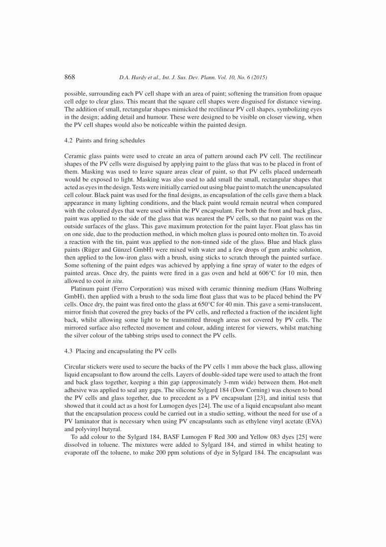
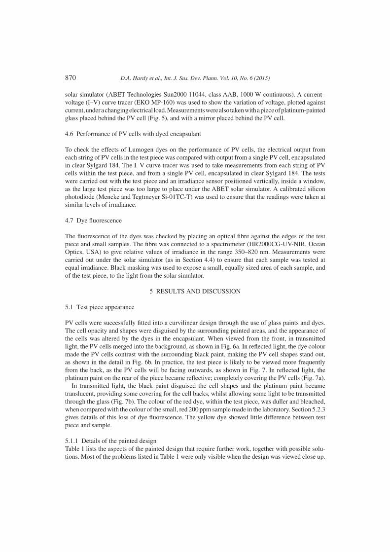
PV cells were successfully fitted into a curvilinear design through the use of glass paints and dyes. The cell opacity and shapes were disguised by the surrounding painted areas, and the appearance of the cells was altered by the dyes in the encapsulant. When viewed from the front, in transmitted light, the PV cells merged into the background, as shown in Fig. 6a. In reflected light, the dye colour made the PV cells contrast with the surrounding black paint, making the PV cell shapes stand out, as shown in the detail in Fig. 6b. In practice, the test piece is likely to be viewed more frequently from the back, as the PV cells will be facing outwards, as shown in Fig. 7. In reflected light, the platinum paint on the rear of the piece became reflective; completely covering the PV cells (Fig. 7a).
In transmitted light, the black paint disguised the cell shapes and the platinum paint became translucent, providing some covering for the cell backs, whilst allowing some light to be transmitted through the glass (Fig. 7b). The colour of the red dye, within the test piece, was duller and bleached, when compared with the colour of the small, red 200 ppm sample made in the laboratory. Section 5.2.3 gives details of this loss of dye fluorescence. The yellow dye showed little difference between test piece and sample.
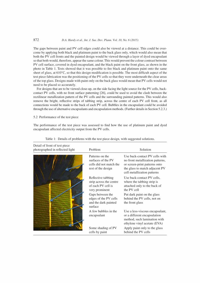
5.1.1 Details of the painted designTable 1 lists the aspects of the painted design that require further work, together with possible solu-tions. Most of the problems listed in Table 1 were only visible when the design was viewed close up.
D.A. Hardy et al., Int. J. Sus. Dev. Plann. Vol. 10, No. 6 (2015) 871
Figure 6: Front view of the 600 mm × 450 mm test piece photographed (a) (left): in a window aperturein transmitted light and (b) (right): a detail of the test piece placed over a black backing and photographed in reflected light so that the PV cells contrast with the surrounding paintwork.
Figure 7: Rear views of the 600 mm × 450 mm test piece placed in a window aperture, from left to right: (a) in reflected light (photographed with a flash) and (b) a detail in transmitted light.
872 D.A. Hardy et al., Int. J. Sus. Dev. Plann. Vol. 10, No. 6 (2015)
The gaps between paint and PV cell edges could also be viewed at a distance. This could be over-come by applying both black and platinum paint to the back glass only, which would also mean that both the PV cell fronts and the painted design would be viewed through a layer of dyed encapsulant so that both would, therefore, appear the same colour. This would prevent the colour contrast between PV cell surface, covered in dyed encapsulant, and the black paint on the front glass, as shown in the photo in Table 1. Tests showed that it was possible to fire black and platinum paint onto the same sheet of glass, at 610°C, so that this design modification is possible. The most difficult aspect of the test piece fabrication was the positioning of the PV cells so that they were underneath the clear areas of the top glass. Designs made with paint only on the back glass would mean that PV cells would not need to be placed so accurately.
For designs that are to be viewed close-up, on the side facing the light source for the PV cells, back-contact PV cells, with no front surface patterning [26], could be used to avoid the clash between the rectilinear metallization pattern of the PV cells and the surrounding painted patterns. This would also remove the bright, reflective strips of tabbing strip, across the centre of each PV cell front, as all connections would be made to the back of each PV cell. Bubbles in the encapsulant could be avoided through the use of alternative encapsulants and encapsulation methods. (Further details in Section 5.2.3.)
5.2 Performance of the test piece
The performance of the test piece was assessed to find how the use of platinum paint and dyed encapsulant affected electricity output from the PV cells.
Table 1: Details of problems with the test piece design, with suggested solutions.
Detail of front of test piece photographed in reflected light Problem Solution
Patterns on the surfaces of the PV cells did not match the rest of the design
Use back-contact PV cells with no front metallization patterns, or screen-print patterns onto the glass to match adjacent PV cell metallization patterns
Reflective tabbing strip across the centre of each PV cell is very prominent
Use back-contact PV cells, where the tabbing strip is attached only to the back of the PV cell
Gaps between the edges of the PV cells and the dark painted surface
Put dark paint on the glass behind the PV cells, not on the front glass
A few bubbles in the encapsulant
Use a less-viscous encapsulant, or a different encapsulation method, such lamination with ethylene vinyl acetate (EVA)
Some shading of PV cells by paint
Apply paint only to the glass behind the PV cells
D.A. Hardy et al., Int. J. Sus. Dev. Plann. Vol. 10, No. 6 (2015) 873
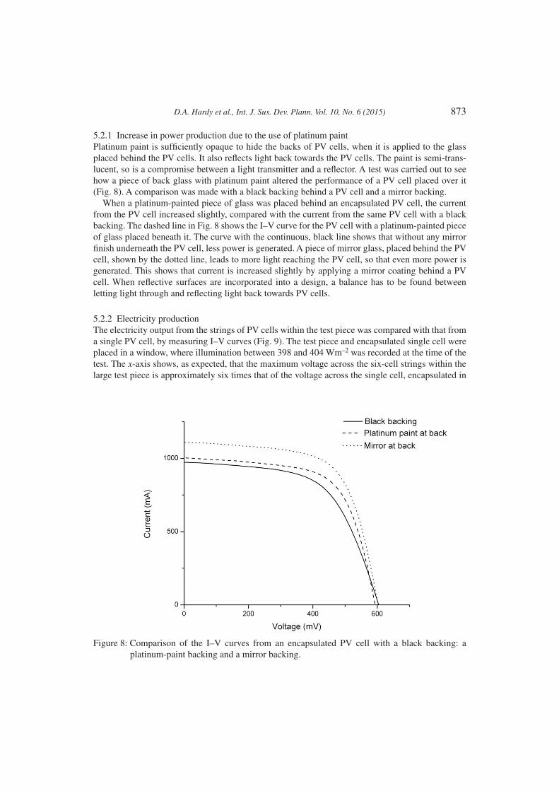
5.2.1 Increase in power production due to the use of platinum paintPlatinum paint is sufficiently opaque to hide the backs of PV cells, when it is applied to the glass placed behind the PV cells. It also reflects light back towards the PV cells. The paint is semi-trans-lucent, so is a compromise between a light transmitter and a reflector. A test was carried out to see how a piece of back glass with platinum paint altered the performance of a PV cell placed over it (Fig. 8). A comparison was made with a black backing behind a PV cell and a mirror backing.
When a platinum-painted piece of glass was placed behind an encapsulated PV cell, the current from the PV cell increased slightly, compared with the current from the same PV cell with a black backing. The dashed line in Fig. 8 shows the I–V curve for the PV cell with a platinum-painted piece of glass placed beneath it. The curve with the continuous, black line shows that without any mirror finish underneath the PV cell, less power is generated. A piece of mirror glass, placed behind the PV cell, shown by the dotted line, leads to more light reaching the PV cell, so that even more power is generated. This shows that current is increased slightly by applying a mirror coating behind a PV cell. When reflective surfaces are incorporated into a design, a balance has to be found between letting light through and reflecting light back towards PV cells.
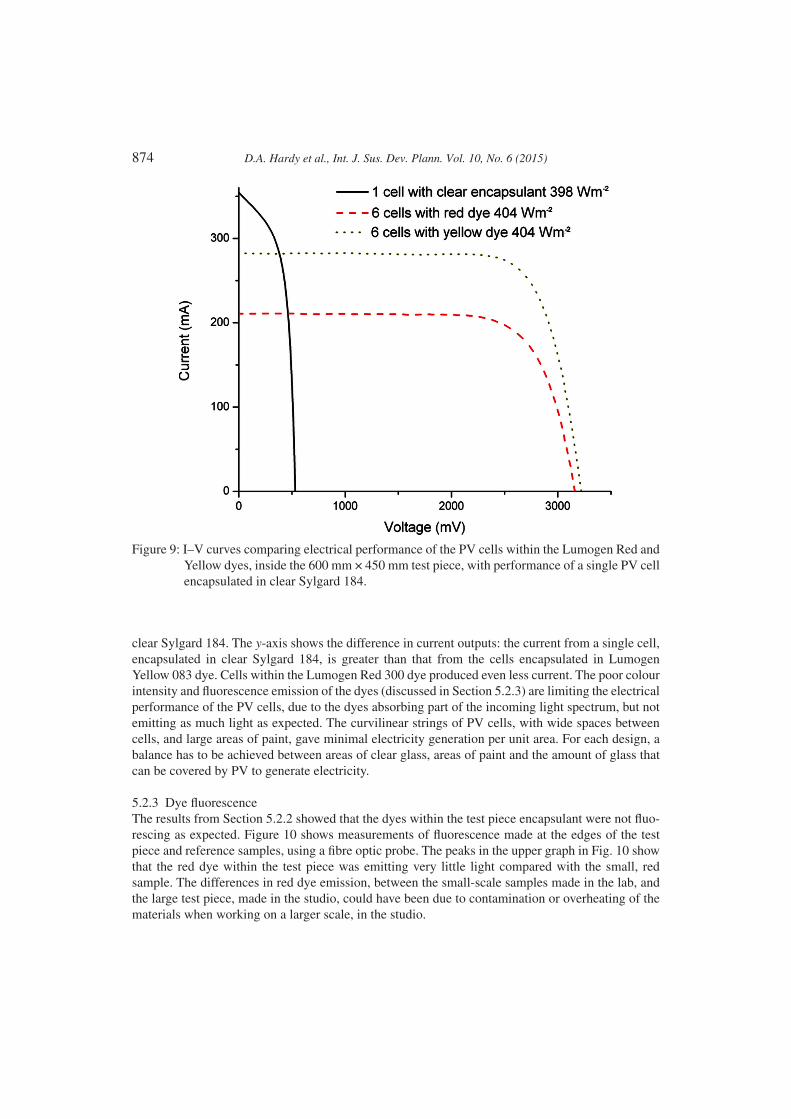
5.2.2 Electricity productionThe electricity output from the strings of PV cells within the test piece was compared with that from a single PV cell, by measuring I–V curves (Fig. 9). The test piece and encapsulated single cell were placed in a window, where illumination between 398 and 404 Wm–2 was recorded at the time of the test. The x-axis shows, as expected, that the maximum voltage across the six-cell strings within the large test piece is approximately six times that of the voltage across the single cell, encapsulated in
Figure 8: Comparison of the I–V curves from an encapsulated PV cell with a black backing: a platinum-paint backing and a mirror backing.
874 D.A. Hardy et al., Int. J. Sus. Dev. Plann. Vol. 10, No. 6 (2015)
clear Sylgard 184. The y-axis shows the difference in current outputs: the current from a single cell, encapsulated in clear Sylgard 184, is greater than that from the cells encapsulated in Lumogen Yellow 083 dye. Cells within the Lumogen Red 300 dye produced even less current. The poor colour intensity and fluorescence emission of the dyes (discussed in Section 5.2.3) are limiting the electrical performance of the PV cells, due to the dyes absorbing part of the incoming light spectrum, but not emitting as much light as expected. The curvilinear strings of PV cells, with wide spaces between cells, and large areas of paint, gave minimal electricity generation per unit area. For each design, a balance has to be achieved between areas of clear glass, areas of paint and the amount of glass that can be covered by PV to generate electricity.
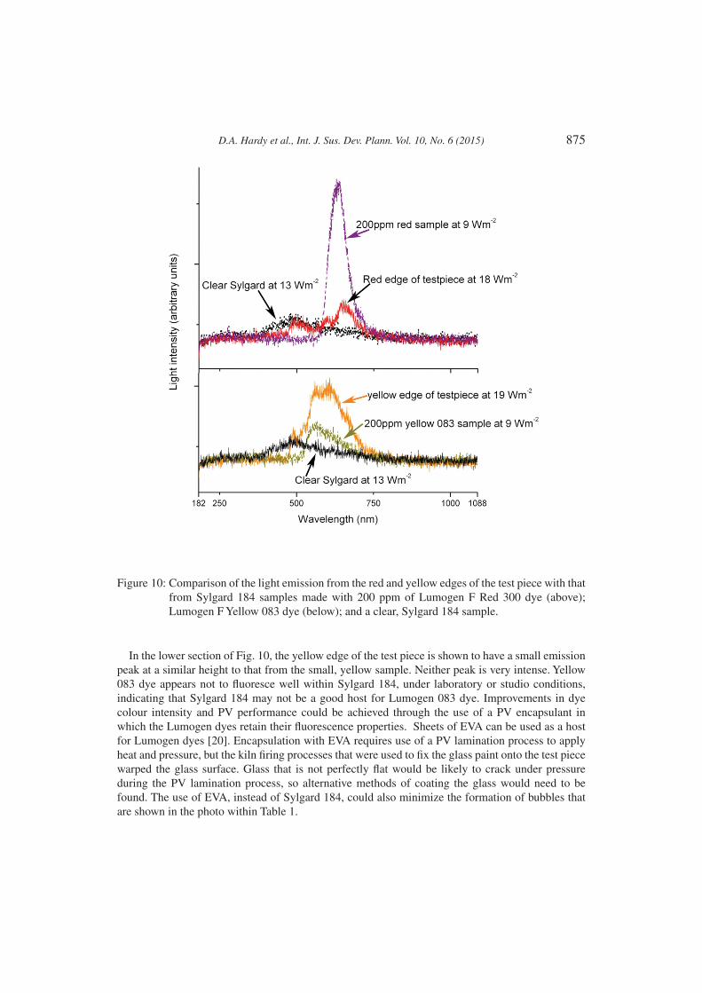
5.2.3 Dye fluorescenceThe results from Section 5.2.2 showed that the dyes within the test piece encapsulant were not fluo-rescing as expected. Figure 10 shows measurements of fluorescence made at the edges of the test piece and reference samples, using a fibre optic probe. The peaks in the upper graph in Fig. 10 show that the red dye within the test piece was emitting very little light compared with the small, red sample. The differences in red dye emission, between the small-scale samples made in the lab, and the large test piece, made in the studio, could have been due to contamination or overheating of the materials when working on a larger scale, in the studio.
Figure 9: I–V curves comparing electrical performance of the PV cells within the Lumogen Red and Yellow dyes, inside the 600 mm × 450 mm test piece, with performance of a single PV cell encapsulated in clear Sylgard 184.
D.A. Hardy et al., Int. J. Sus. Dev. Plann. Vol. 10, No. 6 (2015) 875
In the lower section of Fig. 10, the yellow edge of the test piece is shown to have a small emission peak at a similar height to that from the small, yellow sample. Neither peak is very intense. Yellow 083 dye appears not to fluoresce well within Sylgard 184, under laboratory or studio conditions, indicating that Sylgard 184 may not be a good host for Lumogen 083 dye. Improvements in dye colour intensity and PV performance could be achieved through the use of a PV encapsulant in which the Lumogen dyes retain their fluorescence properties. Sheets of EVA can be used as a host for Lumogen dyes [20]. Encapsulation with EVA requires use of a PV lamination process to apply heat and pressure, but the kiln firing processes that were used to fix the glass paint onto the test piece warped the glass surface. Glass that is not perfectly flat would be likely to crack under pressure during the PV lamination process, so alternative methods of coating the glass would need to be found. The use of EVA, instead of Sylgard 184, could also minimize the formation of bubbles that are shown in the photo within Table 1.
Figure 10: Comparison of the light emission from the red and yellow edges of the test piece with that from Sylgard 184 samples made with 200 ppm of Lumogen F Red 300 dye (above); Lumogen F Yellow 083 dye (below); and a clear, Sylgard 184 sample.

876 D.A. Hardy et al., Int. J. Sus. Dev. Plann. Vol. 10, No. 6 (2015)
5.3 Further developments
For each new design incorporating PV within architectural glass, decisions will need to be made about the amount by which the PV cells are to be made visible or disguised. The methods described in this article give a start point, showing that it is possible to incorporate PV cells within a variety of architectural glass designs, with choice as to the level of prominence of the PV cell shapes and string patterns. The painting and colour addition methods described in this article could be developed through the use of alternative materials and techniques. The methods that improve c-Si PV performance are:
• The use of reflective materials: it was demonstrated in Section 5.2.1 that this can boost the short-circuit current from PV placed over the reflective materials.
• The use of fluorescent dyes within encapsulant materials such as EVA. Although the addition of dyes to Sylgard 184 was unsuccessful in this instance, it has been demonstrated that the same dyes can enhance PV performance when used within dyed encapsulant that is applied over and around c-Si PV cells [20,21].
Although Lumogen dyes are quite stable when compared with other dye molecules, in general, organic dyes are not yet sufficiently durable to make this particular technology viable for installations that are to last for more than 20 years: the guaranteed lifetime of standard PV modules. For this technology to be viable in architectural glass installations, dye replenishment or replacement of materials will be required; or a product with a shorter ‘useful’ lifetime identified. Alternative methods of colour addition would be to use coloured glass, or translucent glass paints or films behind the PV cells. This would create contrast between the PV cell surface colour and the surrounding translucent areas of glazing, but this would only be conspicuous in designs that were to be viewed close-up on the side facing the light source.
5.3.1 Alternatives to glass paint The use of glass coatings or decals, instead of traditional glass paint, would remove the need for kiln firing to fix glass paint. Materials with the levels of permanence appropriate to each project could be chosen. This would also make it easier to create designs that conform to safety standards [25]. This is particularly applicable to the platinum paint that was applied to the back glass, which cannot be toughened, as the reflective surface prevents the heat treatment from being carried out correctly. As platinum paint can be used to increase PV efficiency, an alternative is required: a method of applying a translucent, reflective coating to selected areas of glass before or after glass toughening or lamination. The ideal coating would have the properties of reflecting a proportion of light back to c-Si PV at the same time as matching the c-Si PV colour and pattern to disguise the PV within designs. Continuing innovation in the development of glass coatings, including coatings that improve the thermal performance of buildings [27], and manipulation of these to give iridescent coatings [28], means that there is plenty of scope for this area of development.
5.3.2 Use of alternative types of PVMost existing, decorative, architectural glass incorporates individual c-Si PV cells. These individual PV cells can be placed wherever they are required within a design. Many other types of PV are made by direct application of semiconducting thin films to substrates [29–31]. These methods could be ideal for use in architectural glass, but the rectilinear modules that are produced are often unsuitable for designs where variable placement of opaque and light-transmitting areas is required. If the
D.A. Hardy et al., Int. J. Sus. Dev. Plann. Vol. 10, No. 6 (2015) 877
challenges of improved thin-film PV efficiencies and lifetimes can be combined with choice of substrate colour and choice of placement of light-transmitting areas of glazing, then alternatives to crystalline PV will become more useful for creation of varied decorative glass designs that incorporate PV.
6 CONCLUSIONSA 450 mm × 600 mm architectural glass test piece was made, incorporating curved PV cell strings; glass paints; and Lumogen F dyes within the Sylgard 184 PV encapsulant. The opacity and rectilinear shapes of the PV cells were successfully blended into a curvilinear design, through the use of glass paint. Translucent platinum paint, applied to the glass behind PV cells, disguised the backs of the PV cells, whilst creating a slight increase in current produced by the PV cells. Black paint was applied to the glass surrounding the fronts of the PV cells, blending the opaque PV cells into a design. These painting techniques could be developed by application of both black and platinum paint to the black glass only, and by the use of alternative methods of applying coatings to glass.
Sylgard 184 was used to encapsulate the PV cells within the test piece. Fluorescent, Lumogen dyes were used to add colour to the encapsulant. The translucent red and yellow altered the test piece appearance, including the apparent colour of the PV cell surfaces. The dye properties were affected by addition to Sylgard 184, so that the Lumogen F Red colour became faded when the mixing process was moved from small-scale laboratory preparation to a larger scale in the studio. Both dyes exhibited poor fluorescence emission within the Sylgard 184 host. There was a resulting fall in current produced by the PV cells that were covered by the dyed encapsulant. Alternative materials and methods are required to maintain good PV cell efficiency, and EVA is suggested as a better host material for Lumogen dyes.
Development of this methodology demonstrates that PV cells can actually be blended into a wide range of architectural glass art, including curvilinear and colourful designs, as long as the opacity and shapes of the PV cells and cell strings are taken into account. This provides new opportunities to make PV more flexible and attractive to a new generation of designers, who wish to incorporate low carbon and net-zero energy motifs into the design of their building envelopes in exciting ways.
ACKNOWLEGEMENTSThe authors are grateful for the support from the following organizations: Peters Studios (Germany), where the test designs were developed; The Leverhulme Trust (UK) for funding the project; The Spires Network (UK) for travel funding; Sigrid Blekastad (Norway) for design and fabrication of the glass in Fig. 1a; Sunovation (Germany) for a PV encapsulant and stickers; E. Jordan Brookes (USA) for tabbing strip; Solar Capture Technologies (UK) for permission to publish the photo in Fig. 1b. This article is a development of a paper for Eco-architecture V: The Fifth International Conference on Harmonisation between Nature and Architecture [32].
REFERENCES[1] Roaf, S., Hyde, R., Campbell, C. & Seigert, M., Transforming markets in the built environment
and adapting to climate change: an introduction. Architectural Science Review, 53(1), pp. 3–11, 2010. doi: http://dx.doi.org/10.3763/asre.2009.0104
[2] Roaf, S., Crichton, D. & Nicol, F., Adapting Buildings and Cities for Climate Change, Oxford: Routledge, 2009. doi: http://dx.doi.org/10.1016/b978-1-85617-720-7.00001-2
[3] Scognamiglio, A. & Røstvik, H.N., Photovoltaics and zero energy buildings: a new opportunity and challenge for design. Progress in Photovoltaics: Research and Applications, 21, pp. 1319–1336, 2012. doi: http://dx.doi.org/10.1002/pip.2286
878 D.A. Hardy et al., Int. J. Sus. Dev. Plann. Vol. 10, No. 6 (2015)
[4] Schoen, T., Prasad, D., Ruoss, D., Eiffert, P. & Sørensen, H., Task 7 of the IEA PV Power Systems Program – Achievements and Outlook, 17th European Photovoltaic Solar Conference, 24 October 2001, Munich.
[5] Photon International, Multicrystalline modules will dominate market in 2014, NPD Solarbuzz. Photon International: Aachen, 2013 [9 April 2014]; Available at http://www.photon- international.com/news_archiv/details.aspx?cat=News_PI&sub=worldwide&pub=4&parent=7296.
[6] Hardy, D., Kerrouche, A., Roaf, S. & Richards, B.S., The search for building-integrated PV materials with good aesthetic potential: a survey. PVSAT-7: 7th Photovoltaic Science, Applications and Technology Conference, eds. M.G. Hutchins and N. Pearsall, 6–8 April 2011; Heriot-Watt University, The Solar Energy Society.
[7] Riedel, A., Creating electricity, letting light through. PV Magazine, 71-3, 2010.[8] Reyntiens, P., The Beauty of Stained Glass, Herbert Press: London, 1990.[9] Moor, A., Colours of Architecture, Octopus: London, 2006.
[10] Devenport, S., Roberts, S., Bruton, T.M., Heasman, K., Brown, L., Cole, A., et al., A sum-mary of the havemor project – process development of shaped and coloured solar cells for BIPV applications, 24th European Photovoltaic Solar Energy Conference and Exhibition; 21–25 Sept 2009; Hamburg.
[11] Onyx Solar, Photovoltaic Glass Patterns, Onyx Solar Group LLC: Avila, Spain [27 March 2014], available at http://www.onyxsolar.com/photovoltaic-glass-patterns.html.
[12] Baum, R., Architectural integration of light-transmissive photovoltaic (LTPV). EU PVSEC, 5–9 September 2011, Hamburg.
[13] Baum, R., Studies on light-transmissive photovoltaics (LTPV): patterns of integration into architectural design. Tokyo, 2012.
[14] Farkas, K., Architectural integration of photovoltaics: formal and symbolic aesthetics of photovoltaics [PhD], Norwegian University of Science and Technology: Trondheim, 2013.
[15] oensgen, J., Solar-Kunst am Parkhaus Pilgrimstein, Marburg [9 April 2014]; available at https://http://www.marburg.de/sixcms/detail.php?template=bild_template&id=96054&ges_id=5.
[16] Goodpasture, L., Art and Design: Art for Architecture, 2011 [6 August 2012]; available at http://www.lynngoodpasture.com/portfolio/portfolio.html.
[17] Hall, S., ‘Lux Nova’ wind tower with solar cells, Regent College, University of British Columbia, Vancouver, British Columbia, Canada [9 September 2012]; available at http://www.SarahHallStudio.com/portfolio.html.
[18] orrado, C., Leow, S.W., Osborn, M., Chan, E., Balaban, B. & Carter, S.A., Optimization of gain and energy conversion efficiency using front-facing photovoltaic cell luminescent solar concentrator design. Solar Energy Materials and Solar Cells, 111(0), pp. 74–81, 2013. doi: http://dx.doi.org/10.1016/j.solmat.2012.12.030
[19] Klampaftis, E., Ross, D., McIntosh, K.R. & Richards, B.S., Enhancing the performance of solar cells via luminescent down-shifting of the incident spectrum: a review. Solar Energy Materials and Solar Cells, 93(8), pp. 1182–1194, 2009. doi: http://dx.doi.org/10.1016/j. solmat.2009.02.020
[20] Klampaftis, E. & Richards, B.S., Improvement in multi-crystalline silicon solar cell efficiency via addition of luminescent material to EVA encapsulation layer. Progress in Photovoltaics: Research and Applications, 19(3), pp. 345–351, 2011. doi: http://dx.doi.org/10.1002/pip.1019
[21] Hardy, D., Kerrouche, A., Roaf, S.C. & Richards, B.S., Improving the aesthetics of photovoltaics through use of coloured encapsulants. PLEA2013 – 29th Conference: Sustainable Architecture for a Renewable Future, 10–12 Septembber 2013, Munich: Technische Universität München.
D.A. Hardy et al., Int. J. Sus. Dev. Plann. Vol. 10, No. 6 (2015) 879
[22] angopadhyay, U., Jana, S. & Das, S., State of art of solar photovoltaic technology. Conference Papers in Energy, 2013, p. 9, 2013. doi: http://dx.doi.org/10.1155/2013/764132
[23] Dross, F., Labat, A., Antonio Perez Lopez, M., Antonio Perez Lopez, M., Raudez, R., Bruce, A., et al., Vacuum-free, cost-effective, developing-country-material-available solar cell encapsulation. Solar Energy Materials and Solar Cells, 90(14), pp. 2159–2166, 2006. doi: http://dx.doi.org/10.1016/j.solmat.2006.02.011
[24] Hardy, D., Kerrouche, A., Roaf, S. & Richards, B., A silicone host for lumogen dyes. PVSAT-8: 8th Photovoltaic Science, Applications and Technology Conference, eds. M. Hutchins, N. Pearsall & A. Cole, Northumbria University: Newcastle, 2012. The Solar Energy Society.
[25] BASF, Lumogen F Collector Dyes: Technical Information. BASF: Ludwigshafen, Germany, 1997 [20 April 2012]; available at http://www2.basf.us/additives/pdfs/p3201e.pdf.
[26] Kerschaver, E.V. & Beaucarne, G., Back-contact solar cells: a review. Progress in Photovoltaics: Research and Applications, 14(2), pp. 107–123, 2006. doi: http://dx.doi.org/10.1002/pip.657
[27] Wilberforce, R., ed., The Link Between Glazing and Climate Change. Glass in Buildings, The Centre for Window and Cladding Technology: Bath, 1999.
[28] Leatherland, E., Possibilites for the use of Low emissivity glass by surface coating manipulation within a creative contex [PhD]. University of Sunderland: Sunderland, 2012.
[29] Roberts, S. & Guariento, N., Building Integrated Photovoltaics: A Handbook, Birkhauser: Basel, 2009.
[30] Aberle, A.G., Thin-film solar cells. Thin Solid Films, 517(17), pp. 4706–4710, 2009. doi: http://dx.doi.org/10.1016/j.tsf.2009.03.056
[31] Po, R., Bernardi, A., Calabrese, A., Carbonera, C., Corso, G. & Pellegrino, A., From lab to fab: how must the polymer solar cell materials design change? – an industrial perspective. Energy & Environmental Science, 7(3), pp. 925–943, 2014. doi: http://dx.doi.org/10.1039/c3ee43460e
[32] Hardy, D.A., Roaf, S.C. & Richards, B.S., Improving the aesthetics of photovoltaics in decorative architectural glass, WIT Transactions on the Built Environment, 142, 2014, ISSN 1743-3509. doi: http://dx.doi.org/10.2495/arc140331