Embed Size (px)
Citation preview
Integrating models and apps across the “Vee” for MBSE
Manas Bajaj, PhD Chief Systems Officer [email protected]
www.intercax.com
Aerospace Breakout Session INCOSE IW, Torrance, CA
Jan 24-25, 2015
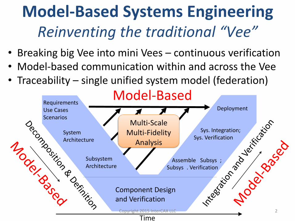
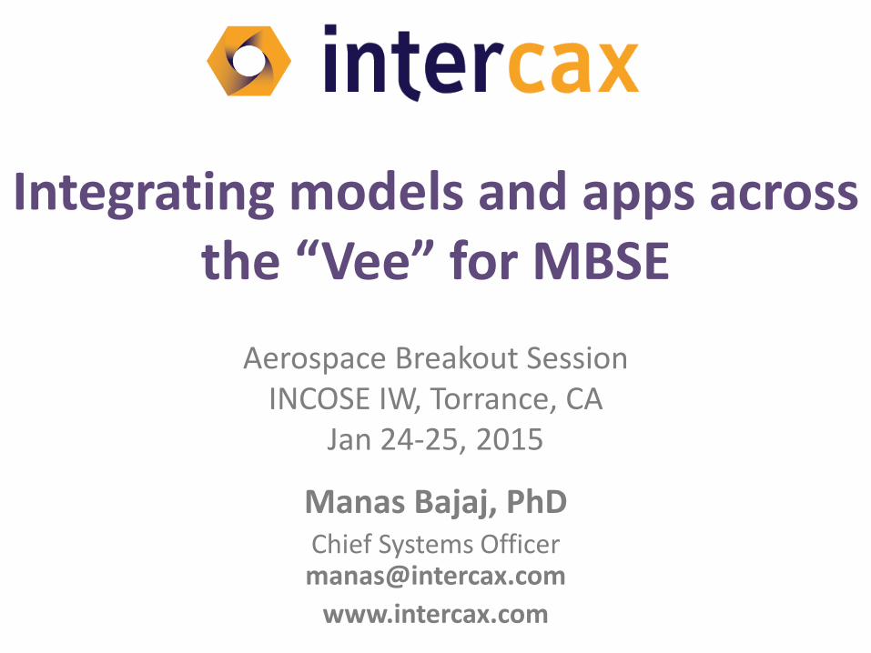
Model-Based
Component Design and Verification
Requirements Use Cases Scenarios
Assemble Subsys ; Subsys . Verification
Sys. Integration; Sys. Verification
Deployment
Time
System Architecture
Subsystem Architecture
Model-Based Systems Engineering Reinventing the traditional “Vee”
• Breaking big Vee into mini Vees – continuous verification • Model-based communication within and across the Vee • Traceability – single unified system model (federation)
Multi-Scale Multi-Fidelity
Analysis
Copyright 2015 InterCAX LLC 2
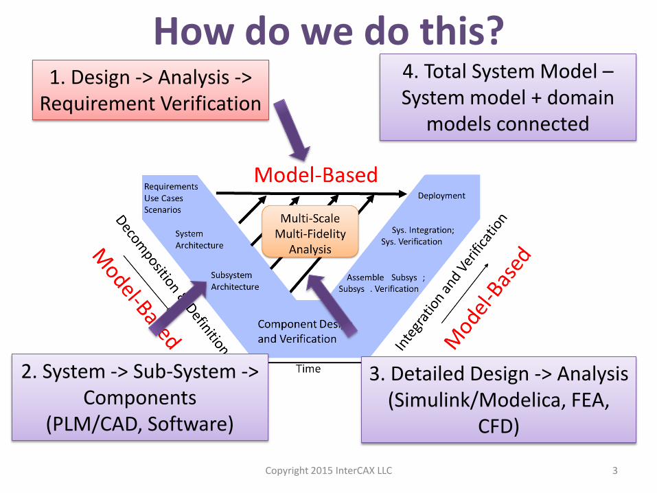
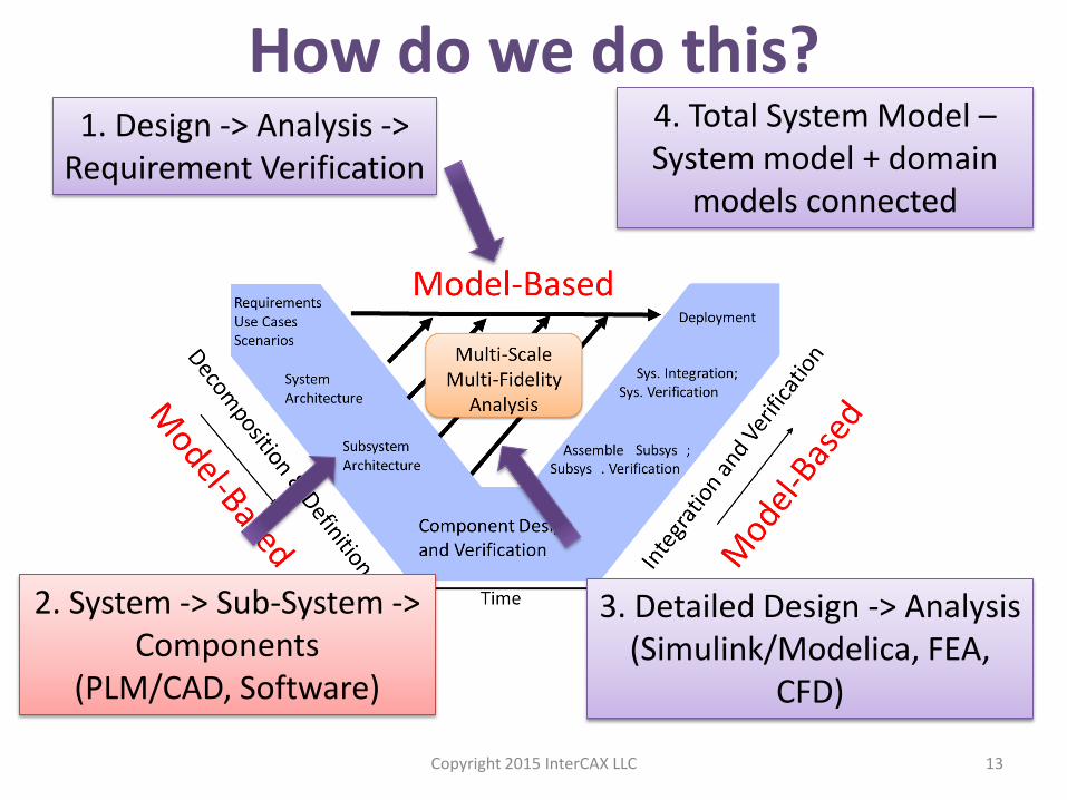
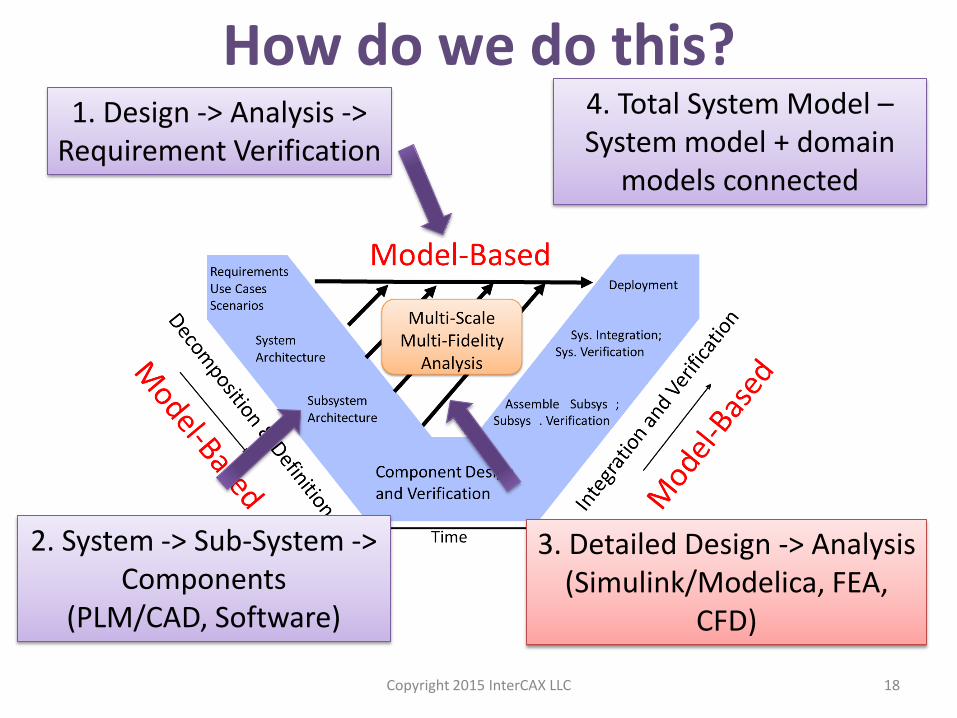
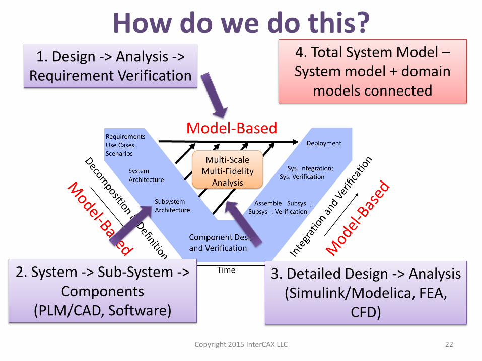
How do we do this? 1. Design -> Analysis ->
Requirement Verification
2. System -> Sub-System -> Components
(PLM/CAD, Software)
3. Detailed Design -> Analysis (Simulink/Modelica, FEA,
CFD)
4. Total System Model – System model + domain
models connected
Copyright 2015 InterCAX LLC 3
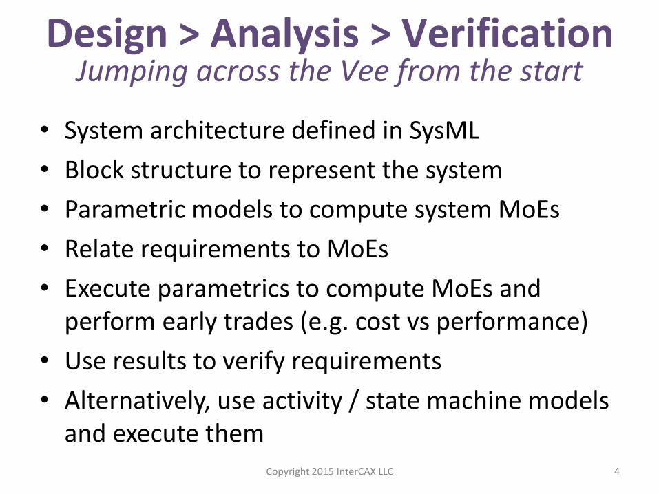
• System architecture defined in SysML
• Block structure to represent the system
• Parametric models to compute system MoEs
• Relate requirements to MoEs
• Execute parametrics to compute MoEs and perform early trades (e.g. cost vs performance)
• Use results to verify requirements
• Alternatively, use activity / state machine models and execute them
4
Design > Analysis > Verification Jumping across the Vee from the start
Copyright 2015 InterCAX LLC
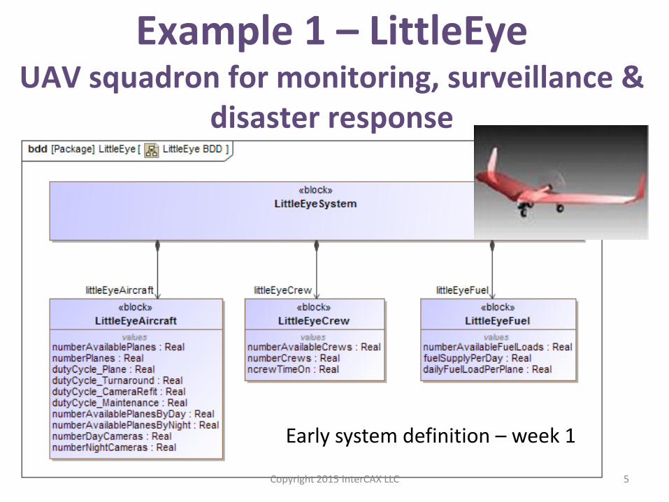
Example 1 – LittleEye UAV squadron for monitoring, surveillance &
disaster response
Early system definition – week 1
Copyright 2015 InterCAX LLC 5
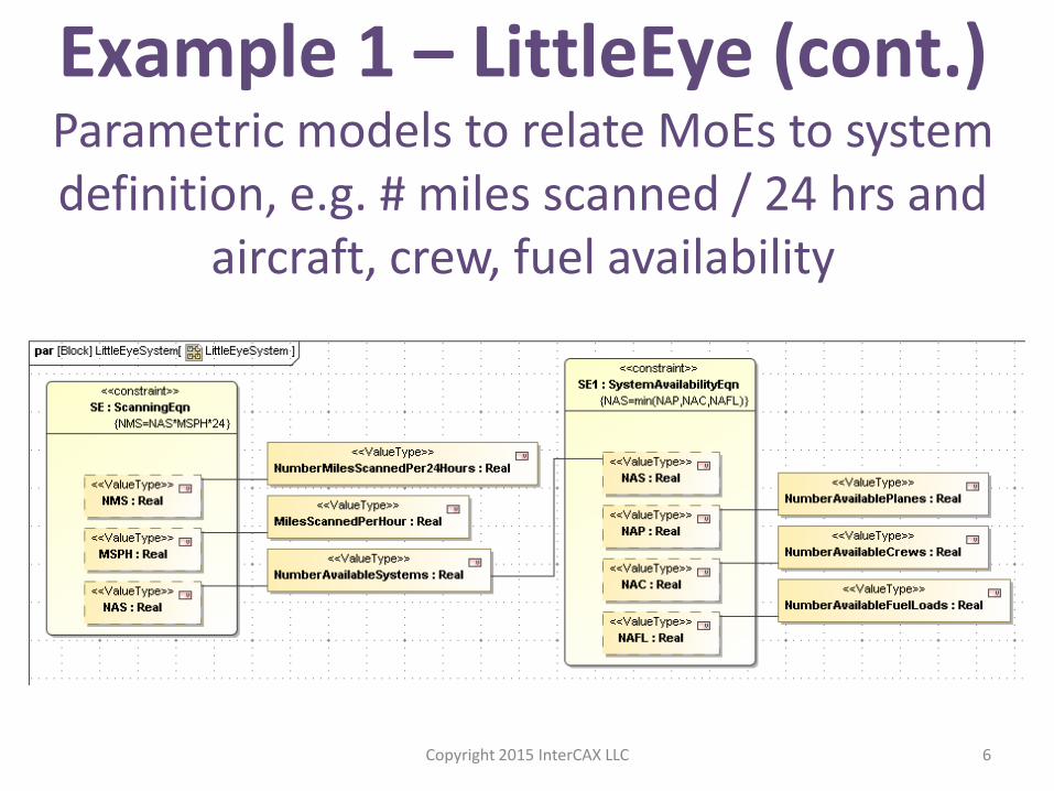
Example 1 – LittleEye (cont.) Parametric models to relate MoEs to system definition, e.g. # miles scanned / 24 hrs and
aircraft, crew, fuel availability
Copyright 2015 InterCAX LLC 6
7
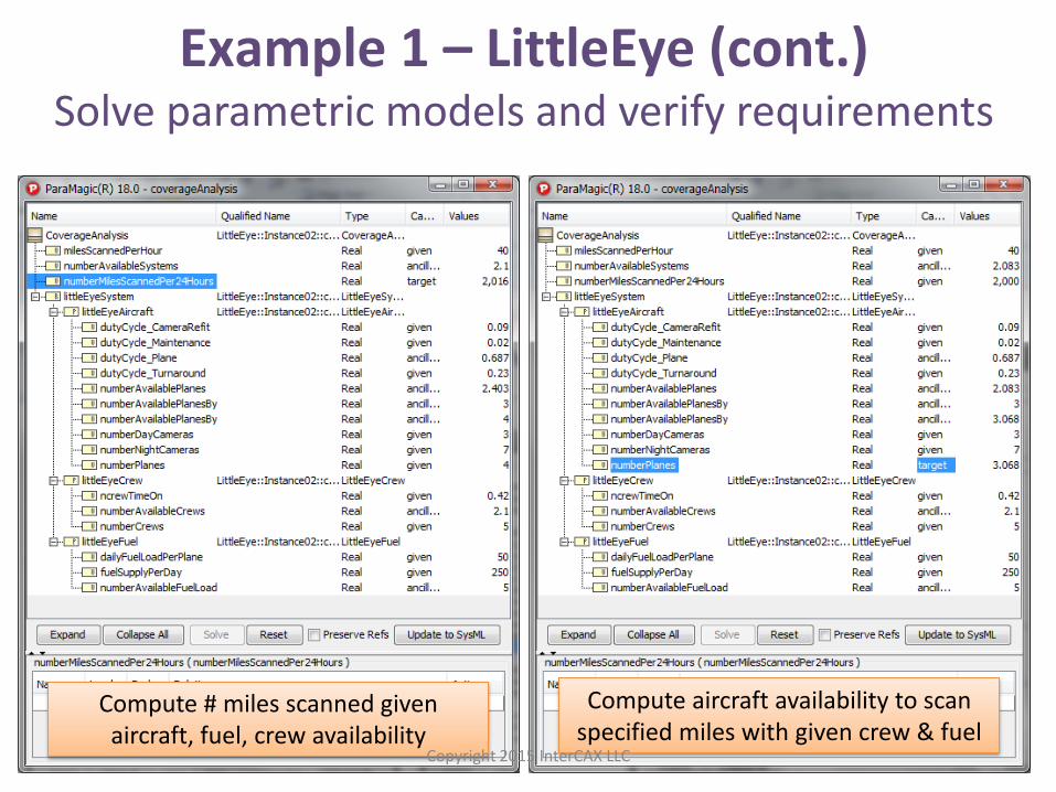
Example 1 – LittleEye (cont.) Solve parametric models and verify requirements
Compute # miles scanned given aircraft, fuel, crew availability
Compute aircraft availability to scan specified miles with given crew & fuel
Copyright 2015 InterCAX LLC
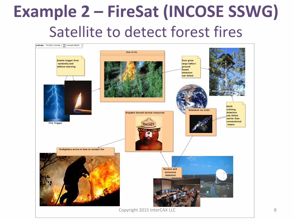
Example 2 – FireSat (INCOSE SSWG) Satellite to detect forest fires
FireSat_Concept Concept Sketchpackage [ ]
Start of Fire
firefighters arrive in time to contain fire
dispatch foreset service resources
Fire Trigger
Detection on orbit
Receive and
announce
detection
Events trigger fires
randomly and
without warning
Earth
orbiting
detection
can detect
ear lier then
conventional
means
fires grow
large before
ground
based
detection
can detect
Copyright 2015 InterCAX LLC 8
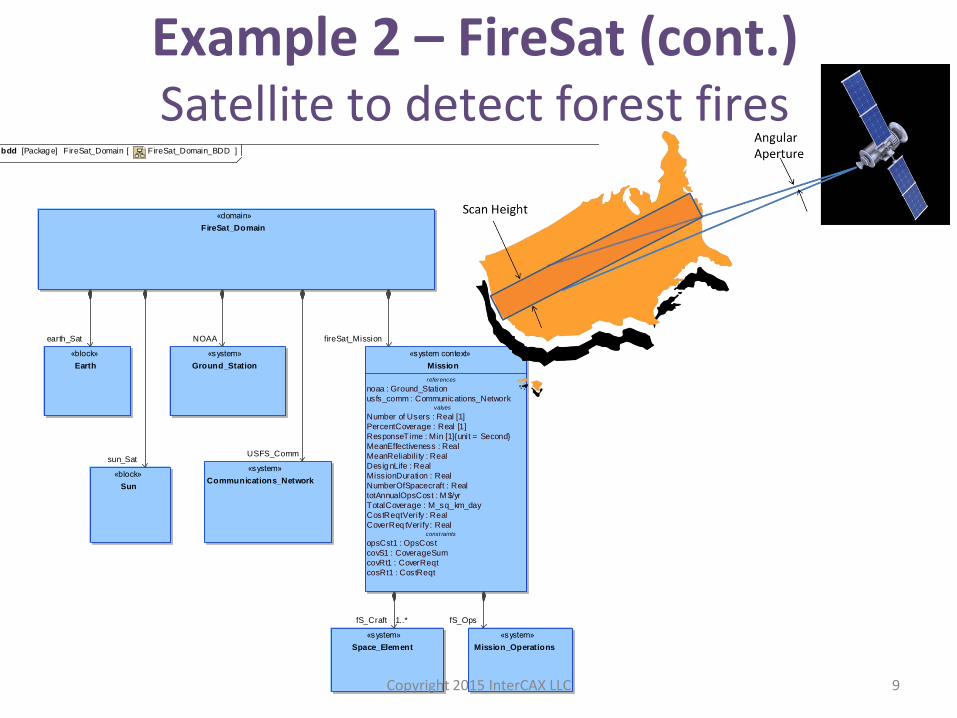
Example 2 – FireSat (cont.) Satellite to detect forest fires
FireSat_Domain_BDDFireSat_Domain[Packag e] bdd [ ]
«domain»
FireSat_Domain
references
noaa : Ground_Station
usfs_comm : Communications_Networkvalues
Number of Users : Real [1]
PercentCoverage : Real [1]
ResponseTime : Min [1]{unit = Second}
MeanEffectiveness : Real
MeanReliabil ity : Real
Desig nLife : Real
MissionDuration : Real
NumberOfSpacecraft : Real
totAnnualOpsCost : M $/yr
TotalCoverage : M_sq_km_day
CostReqtVerify : Real
CoverReq tVerify : Realconst raints
opsCst1 : OpsCost
covS1 : CoverageSum
covRt1 : CoverReqt
cosRt1 : CostReqt
«system context»
Mission
Diagram name FireSat_Domain_BDD
Author Zwemer
Creation date 6/21/10 11:46 AM
Modification date 11/3/10 1:15 PM
Documentation
Completion status
Description
Version
«system»
Communications_Network
«system»
Ground_Station
«system»
Space_Element
«system»
Mission_Operations
«block»
Earth
«block»
Sun
sun_SatUSFS_Comm
NOAAearth_Sat fireSat_Mission
fS_OpsfS_Craft 1..*
Copyright 2015 InterCAX LLC 9
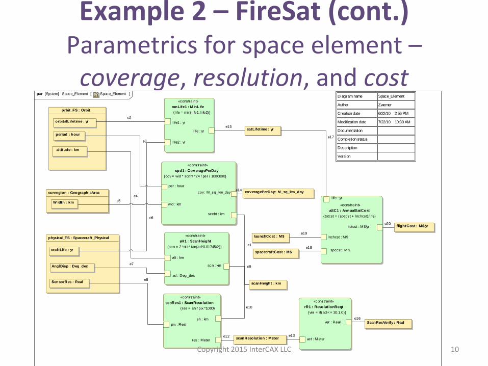
Example 2 – FireSat (cont.) Parametrics for space element –
coverage, resolution, and cost Space_Element Space_Element[System] par [ ]
Diagram name Space_Element
Author Zwemer
Creation date 6/22/10 2:56 PM
Modification date 7/22/10 10:30 AM
Documentation
Completion status
Description
Version
«constraint»
cpd1 : Cov eragePerDay
{cov = wid * scnht *24 / per / 1000000}
cov : M_sq_km_day
per : hour
scnht : km
wid : km
AnglDisp : Deg_dec
SensorRes : Real
craftLife : yr
physical_FS : Spacecraft_Physical
cov eragePerDay : M_sq_km_day
«constraint»
aSC1 : AnnualSatCost
{totcst = (spccst + lnchcst)/l ife}
life : yr
lnchcst : M$
spccst : M $
totcst : M$/yr
«constraint»
sH1 : ScanHeight
{scn = 2 *alt * tan(ad*0.01745/2)}
ad : Deg _dec
alt : km
scn : km
orbitalLifetime : yr
altitude : km
period : hour
orbit_FS : Orbit
W idth : km
scnregion : GeographicArea
«constraint»
scnRes1 : ScanResolution
{res = sh / pix *1000}
pix : Real
res : Meter
sh : km
«constraint»
mnLife1 : M inLife
{l ife = min(life1, l ife2)}
life : yr
life1 : yr
life2 : yr
scanResolution : Meter
«constraint»
rR1 : ResolutionReqt
{ver = if(act<= 30,1,0)}
act : M eter
ver : Real ScanResVerify : Real
spacecraftCost : M$
flightCost : M$/yr
scanHeight : km
launchCost : M$
satLifetime : yr
e6
e8
e7
e4
e3
e2
e5
e1
e17
e10
e19
e15
e18
e9
e16
e12 e13
e20
e14
Copyright 2015 InterCAX LLC 10
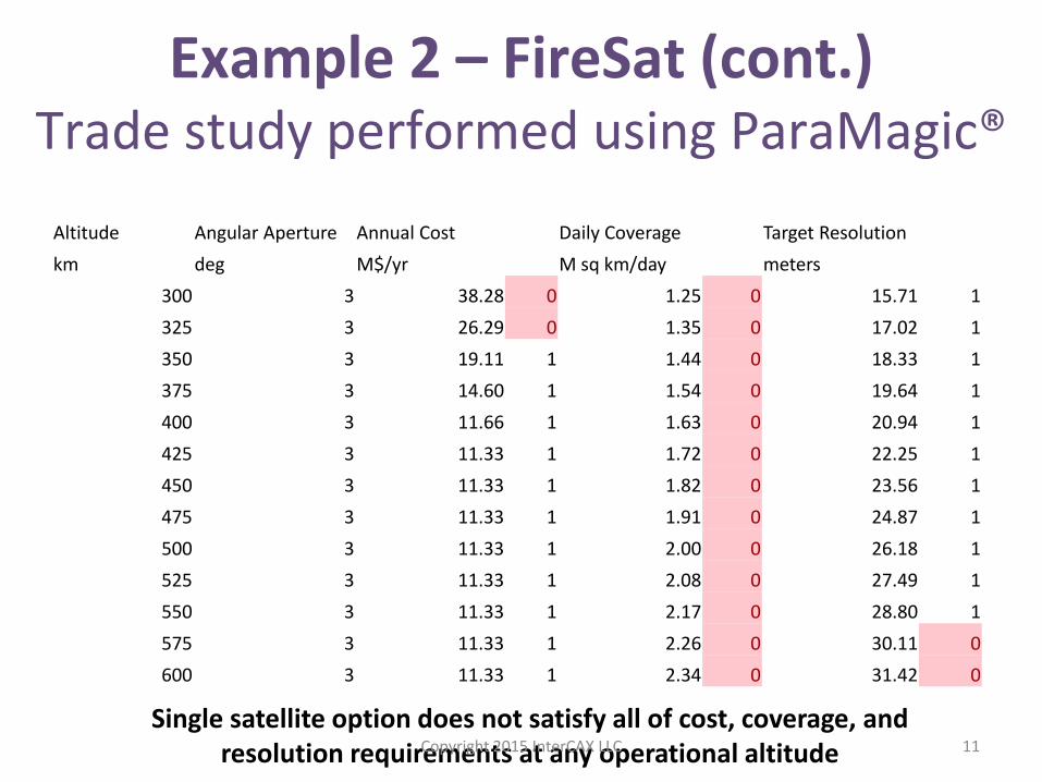
Example 2 – FireSat (cont.) Trade study performed using ParaMagic®
Altitude Angular Aperture Annual Cost Daily Coverage Target Resolution
km deg M$/yr M sq km/day meters
300 3 38.28 0 1.25 0 15.71 1
325 3 26.29 0 1.35 0 17.02 1
350 3 19.11 1 1.44 0 18.33 1
375 3 14.60 1 1.54 0 19.64 1
400 3 11.66 1 1.63 0 20.94 1
425 3 11.33 1 1.72 0 22.25 1
450 3 11.33 1 1.82 0 23.56 1
475 3 11.33 1 1.91 0 24.87 1
500 3 11.33 1 2.00 0 26.18 1
525 3 11.33 1 2.08 0 27.49 1
550 3 11.33 1 2.17 0 28.80 1
575 3 11.33 1 2.26 0 30.11 0
600 3 11.33 1 2.34 0 31.42 0
Single satellite option does not satisfy all of cost, coverage, and resolution requirements at any operational altitude Copyright 2015 InterCAX LLC 11
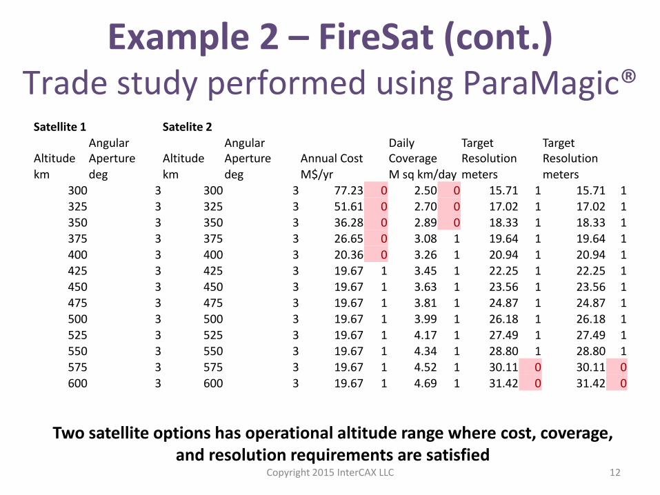
Example 2 – FireSat (cont.) Trade study performed using ParaMagic®
Satellite 1 Satelite 2
Altitude Angular Aperture Altitude
Angular Aperture Annual Cost
Daily Coverage
Target Resolution
Target Resolution
km deg km deg M$/yr M sq km/day meters meters 300 3 300 3 77.23 0 2.50 0 15.71 1 15.71 1 325 3 325 3 51.61 0 2.70 0 17.02 1 17.02 1 350 3 350 3 36.28 0 2.89 0 18.33 1 18.33 1 375 3 375 3 26.65 0 3.08 1 19.64 1 19.64 1
400 3 400 3 20.36 0 3.26 1 20.94 1 20.94 1 425 3 425 3 19.67 1 3.45 1 22.25 1 22.25 1 450 3 450 3 19.67 1 3.63 1 23.56 1 23.56 1 475 3 475 3 19.67 1 3.81 1 24.87 1 24.87 1 500 3 500 3 19.67 1 3.99 1 26.18 1 26.18 1 525 3 525 3 19.67 1 4.17 1 27.49 1 27.49 1 550 3 550 3 19.67 1 4.34 1 28.80 1 28.80 1 575 3 575 3 19.67 1 4.52 1 30.11 0 30.11 0 600 3 600 3 19.67 1 4.69 1 31.42 0 31.42 0
Two satellite options has operational altitude range where cost, coverage, and resolution requirements are satisfied
Copyright 2015 InterCAX LLC 12
How do we do this? 1. Design -> Analysis ->
Requirement Verification
2. System -> Sub-System -> Components
(PLM/CAD, Software)
3. Detailed Design -> Analysis (Simulink/Modelica, FEA,
CFD)
4. Total System Model – System model + domain
models connected
Copyright 2015 InterCAX LLC 13
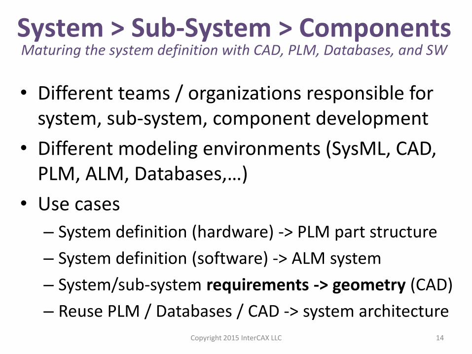
• Different teams / organizations responsible for system, sub-system, component development
• Different modeling environments (SysML, CAD, PLM, ALM, Databases,…)
• Use cases
– System definition (hardware) -> PLM part structure
– System definition (software) -> ALM system
– System/sub-system requirements -> geometry (CAD)
– Reuse PLM / Databases / CAD -> system architecture
14
System > Sub-System > Components Maturing the system definition with CAD, PLM, Databases, and SW
Copyright 2015 InterCAX LLC
15
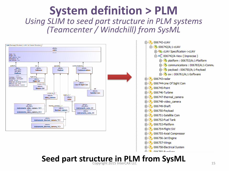
System definition > PLM Using SLIM to seed part structure in PLM systems
(Teamcenter / Windchill) from SysML
Seed part structure in PLM from SysML Copyright 2015 InterCAX LLC
16
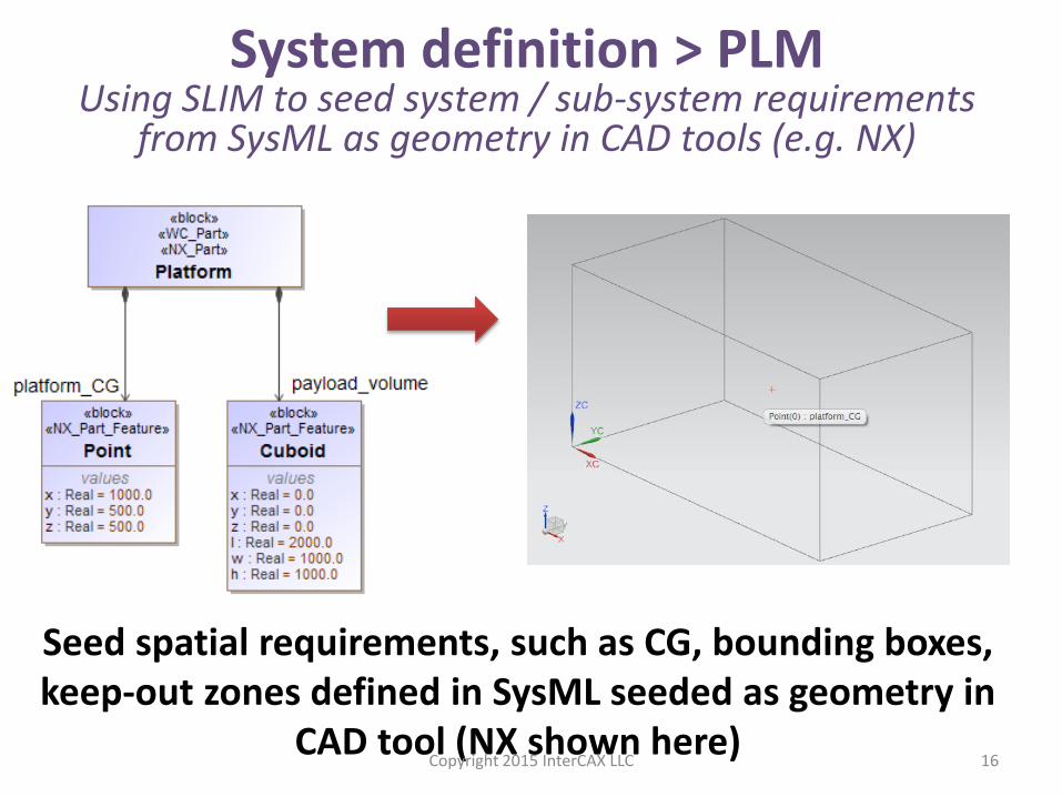
System definition > PLM Using SLIM to seed system / sub-system requirements
from SysML as geometry in CAD tools (e.g. NX)
Seed spatial requirements, such as CG, bounding boxes, keep-out zones defined in SysML seeded as geometry in
CAD tool (NX shown here) Copyright 2015 InterCAX LLC
17
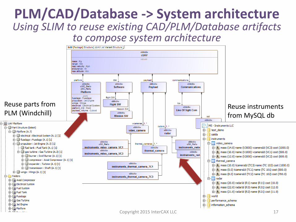
PLM/CAD/Database -> System architecture Using SLIM to reuse existing CAD/PLM/Database artifacts
to compose system architecture
Reuse parts from PLM (Windchill)
Reuse instruments from MySQL db
Copyright 2015 InterCAX LLC
How do we do this? 1. Design -> Analysis ->
Requirement Verification
2. System -> Sub-System -> Components
(PLM/CAD, Software)
3. Detailed Design -> Analysis (Simulink/Modelica, FEA,
CFD)
4. Total System Model – System model + domain
models connected
Copyright 2015 InterCAX LLC 18
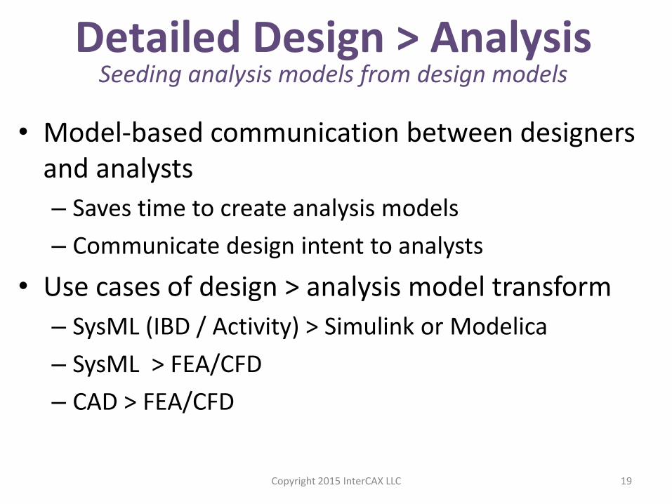
• Model-based communication between designers and analysts
– Saves time to create analysis models
– Communicate design intent to analysts
• Use cases of design > analysis model transform
– SysML (IBD / Activity) > Simulink or Modelica
– SysML > FEA/CFD
– CAD > FEA/CFD
19
Detailed Design > Analysis Seeding analysis models from design models
Copyright 2015 InterCAX LLC
20
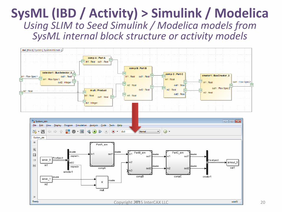
SysML (IBD / Activity) > Simulink / Modelica Using SLIM to Seed Simulink / Modelica models from
SysML internal block structure or activity models
Copyright 2015 InterCAX LLC
21
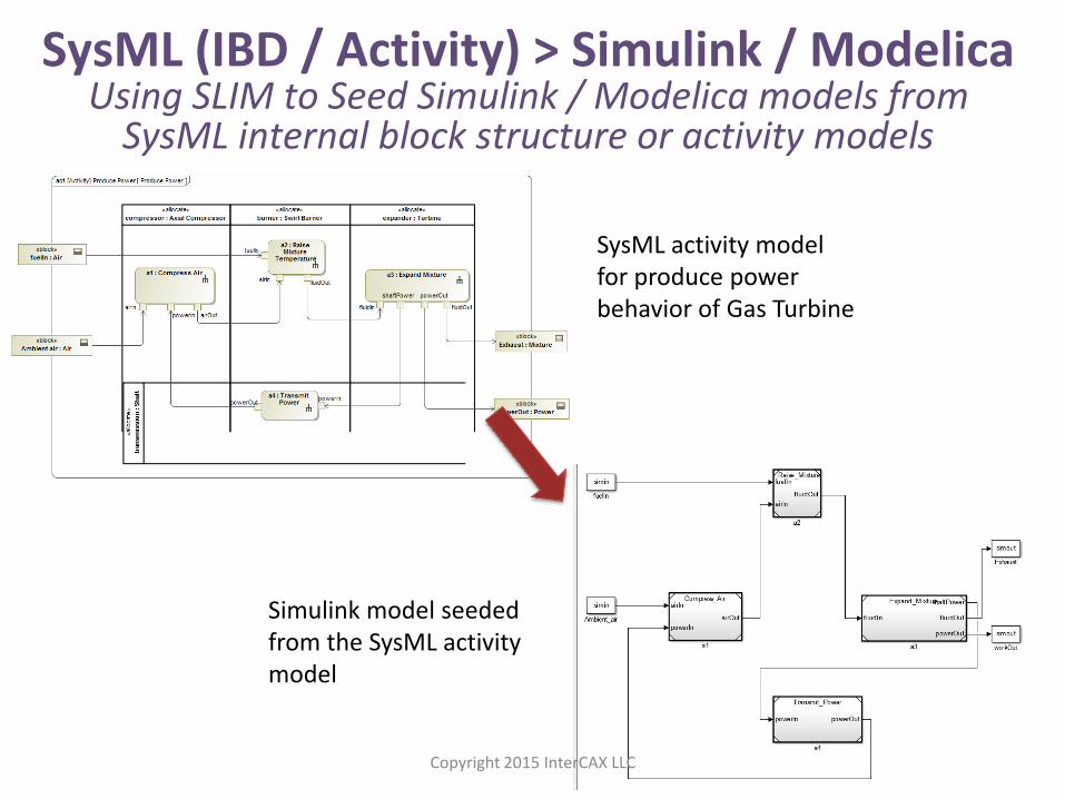
SysML (IBD / Activity) > Simulink / Modelica Using SLIM to Seed Simulink / Modelica models from
SysML internal block structure or activity models
SysML activity model for produce power behavior of Gas Turbine
Simulink model seeded from the SysML activity model
Copyright 2015 InterCAX LLC
How do we do this? 1. Design -> Analysis ->
Requirement Verification
2. System -> Sub-System -> Components
(PLM/CAD, Software)
3. Detailed Design -> Analysis (Simulink/Modelica, FEA,
CFD)
4. Total System Model – System model + domain
models connected
Copyright 2015 InterCAX LLC 22
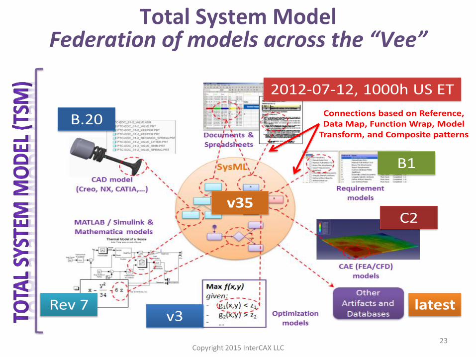
23
v35
B.20
Rev 7
2012-07-12, 1000h US ET
B1
C2
v3latest
Connections based on Reference, Data Map, Function Wrap, Model
Transform, and Composite patterns
Copyright 2015 InterCAX LLC
Total System Model Federation of models across the “Vee”
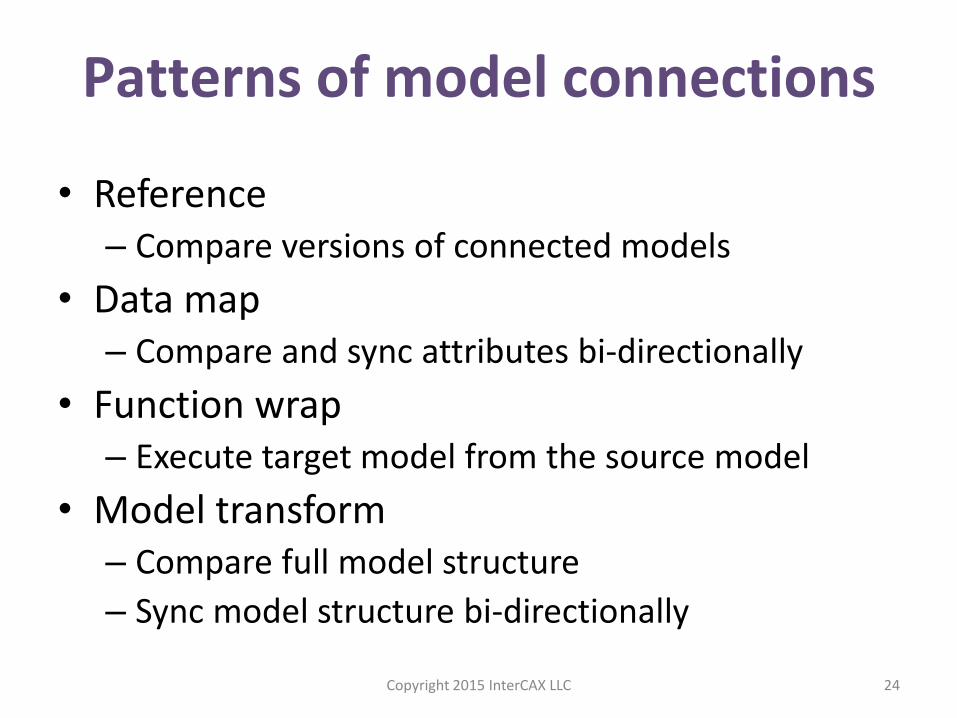
• Reference – Compare versions of connected models
• Data map – Compare and sync attributes bi-directionally
• Function wrap – Execute target model from the source model
• Model transform – Compare full model structure
– Sync model structure bi-directionally
24
Patterns of model connections
Copyright 2015 InterCAX LLC
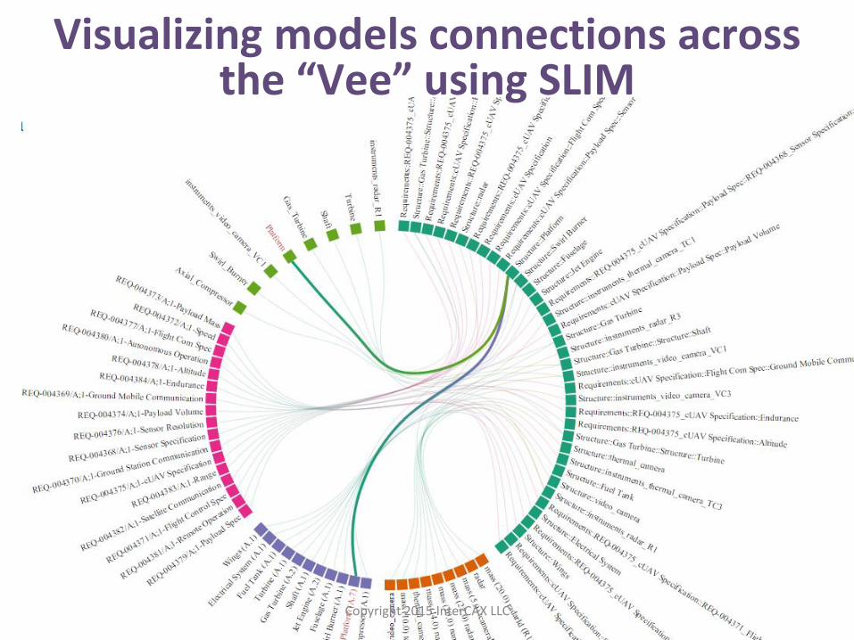
25
Visualizing models connections across the “Vee” using SLIM
Copyright 2015 InterCAX LLC
Questions / Comments
Manas Bajaj, PhD Chief Systems Officer
Dirk Zwemer, PhD President
web: www.intercax.com
email: [email protected]
Twitter @intercax | LinkedIn intercax-llc
Copyright 2015 InterCAX LLC 26
BACKUP SLIDES
Copyright 2015 InterCAX LLC 27
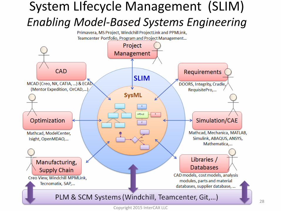
System LIfecycle Management (SLIM) Enabling Model-Based Systems Engineering
28
Copyright 2015 InterCAX LLC