Embed Size (px)
Citation preview

12th Annual Symposium, Mary Kay O’Connor Process Safety Center “Beyond Regulatory Compliance: Making Safety Second Nature”
Texas A&M University, College Station, Texas October 27-28, 2009
Integrating Medium Voltage Switchgear Breakers into a
Safety Instrumented Function
Dave Grattan* PE, CFSE and Sam Nicholson PE, EE S&B Engineers and Constructors, LTD.
7825 Park Place Blvd. Houston, TX 77087
Disclaimer The following paper is provided for educational purposes. While the authors have attempted to describe the material contained herein as accurately as possible, it must be understood that variables in any given application or specification can and will affect the choice of engineering solution for that scenario. All necessary factors must be taken into consideration when designing hazard mitigation for any application. Abstract For some incident outcome scenarios, a risk assessment study has determined the need to include the shutdown of a large electric motor, as part of a safety instrumented function (SIF). In the process industries, it is common practice to control and protect large horsepower motors (typically 2,000 HP and above), with medium voltage switchgear breakers. Safety instrumented functions that include electric motors utilizing medium voltage switchgear for tripping, have unique final element subsystems, which require specialized knowledge in order to implement correctly. This paper will discuss the design considerations for integrating medium voltage switchgear used for shutdown of an electric motor, into a safety instrumented function. First, an overview of typical low and medium voltage electrical equipment used for controlling and protecting electric motors will be discussed. Next, a review of generic sourced failure data for medium voltage switchgear breakers will be presented. Focus will be on the taxonomy used to classify different breaker types, and the relevant failure modes and effects, used for quantifying performance. Next, specific SIF design details for tripping medium voltage switchgear breakers will be analyzed, in the context of achieving a certain integrity level. Parameters to be considered include hardware fault tolerance requirements, voting, available diagnostics, energize v. de-energize to trip shutdown circuits, certified equipment v. proven-in-use, and alternate means of shutdown (including manual intervention and protective relaying). Often times, in a risk assessment study such as a layer of protection analysis (LOPA), multiple actions will be credited for shutdown of a motor, for the same consequence scenario. This paper will analyze the common electrical equipment shared among the multiple actions, and determine how much credit can be taken considering common cause failure. Next, on-line and off-line proof-testing techniques of the safety instrumented function will be explored. Inspection, test, and preventive maintenance (ITPM) of medium voltage switchgear will be discussed, as a means for maintaining the electrical equipment in the “as good as new” condition. Finally, a consideration

of reliability will be made by analyzing how the safety instrumented function (including proof-testing) will impact the machine uptime. Keywords: Contacts, Contactor, Circuit Breaker, Protective Relay, Motor Starter, MCC, Switchgear, Operating Mechanism, Vacuum Interrupter, Low Voltage, Medium Voltage, Undervoltage Trip, Shunt Trip, Mechanical Integrity, Fault Tree, SIF, SIL, LOPA. ACRONYMS/ ABBREVIATIONS 49…………....Machine or transformer thermal relay. A device that functions when the
temperature of a machine armature winding or other load-carrying winding or element of a machine or power transformer exceeds a predetermined value. IEEE Standard Device Number (IEEE Std. C37.2-2008).
52……………AC Circuit Breaker. A device that is used to close and interrupt an ac power circuit under normal conditions or to interrupt this circuit under fault or emergency conditions. IEEE Standard Device Number (IEEE Std. C37.2-2008).
AC Alternating Current CB Circuit Breaker DC Direct Current HFT Hardware Fault Tolerance HP Horsepower IPL Independent Protection Layer KV Kilovolts LOPA Layer of Protection Analysis LV Low Voltage MCC Motor Control Center MCCB Molded Case Circuit Breaker MI Mechanical Integrity MTTF Mean Time to Fail MV Medium Voltage NC Normally Closed NO Normally Open NEMA National Electrical Manufacturers Association PFD Average Probability of Failure on Demand SF6 Sulfur Hexafluoride SIF Safety Instrumented Function SIL Safety Integrity Level SIS Safety Instrumented System SWGR Switchgear PART 1 1.0 INTRODUCTION It is common now to find that a Hazard and Risk Assessment study has identified a requirement to stop a particular electric motor driven machine, to prevent or mitigate a hazard. This function could be part of an independent protection layer (IPL), or a safety instrumented function (SIF). As a typical application to be considered in this paper, we will investigate a 3-phase electric motor used to drive process machinery, for which the contacts of the motor contactor or breaker

will operate closed for many years, and will be required to open when a process demand requires it, thus stopping the motor and the machine it drives, to prevent or mitigate a potential hazard. The treatment is general enough to include induction or synchronous motors, with full voltage or reduced voltage (soft) starting, or with adjustable speed drives. In addition, if the safety function requires the motor to start on demand, the same principles will apply, however the failure mode and other application considerations will be different (see 3.1.2). A safety instrumented function is composed of a sensor, logic solver, and final element (1). For this application, the motor contactor or breaker constitutes the primary component of the final element subsystem. The failure mode we are interested in is failure of a contactor or breaker to open on demand, resulting in failure of the motor to stop. This failure could occur due to a fault in the contactor or breaker operating mechanism, or at the contacts themselves. This failure mode will be referred to as “dangerous.” The function of tripping the motor will have to meet a performance requirement specified as average probability of failure on demand (PFD). In addition, hardware fault tolerance (HFT) requirements have to be met. Mechanical integrity of the installation will be considered to ensure the performance is maintained for the life of the protective function. 1.1 OVERVIEW OF ELECTRIC MOTOR PROTECTION AND CONTROL Several features used to control and protect motors are discussed. Current switching to start and stop motors takes place at the electrical contact. Motors can be classified into low and medium voltage service, and for each the motor will have unique devices for control and protection. Motor starters are enclosed in “buckets” and housed in motor control centers (MCC). Medium voltage circuit breakers are enclosed in switchgear - metal clad or gas insulated. 1.1.1 Electrical Contacts Central to motor protection and control is the electrical contact. Electrical contacts are found in several devices used to switch motor loads, namely relays, contactors, and circuit breakers. A contact is a temporary or ‘releasable’ junction between two current-carrying conductors (2). Closed contacts permit the flow of current in an electrical circuit. Open contacts prevent current flow. Contacts are designed to open under normal current load for use in relays and contactors, while in circuit breakers the contacts are required to interrupt fault (short circuit) current as well. The current-carry ability of the contacts in each device generally increases from relay to contactor to circuit breaker. Contacts are actuated via electromechanical means using a solenoid coil and moveable armature. Electrical contact theory and design has a large body of literature devoted to it (3). Of primary importance are contact size and material, contact force, and contact resistance. 1.1.2 One-line Motor Schematics It is useful when designing a protective function, for which the shutdown of an electric motor is to be the final element, to have an overview of the possible types of motor control that might be encountered. Three of the most commonly used motor control strategies for new installations are show in Figures 1 - 3. The figures represent a “one-line” presentation in which only a single phase (one line) of the three phase motor circuit is shown.

LV MCC (600 V Class)
M
Combination Motor Starter
120 VAC Control Circuit
C
Molded Case Circuit Breaker (with manual disconnect)
Stab-in
Voltage TransformerContactor, air switched
Thermal Over-Load Relay
Bolt-in
Cable
Motor
Bus Bar
Figure 1. Low-voltage MCC The popular combination motor starter with magnetic contactor has been used for decades to control and protect low voltage motors. See Figure 1. The primary components of the combination starter are the contactor (for normal current switching), molded case circuit breaker (fault current switching), and motor overload relay (to protect against mechanical over-load). The MCCB also includes a manual disconnect that will switch load current. The auxiliary control circuit interfaces the contactor with starting and stopping functionality.
MV MCC (5 kV Class)
M
49
Motor Starter/ Controller
120 VAC Control Circuit
Protective Relay
Stab-in
No-load Manual Disconnect switch
Fuse Voltage Transformer
Contactor, vacuum type
Thermal Over-Load RelayCurrent Transformer
Motor
Cable
Bolt-in
Bus Bar
Figure 2. Medium-voltage MCC For medium voltage applications, vacuum contactors and vacuum circuit breakers are used to switch current to protect motors. Other circuit breaker types include Gas (SF6) and Air-Magnetic circuit breakers, for medium voltage applications. The vacuum contactor shown in Figure 2 was developed exclusively to switch motor loads. The medium voltage motor starter includes the vacuum contactor (to switch normal current), fuse (to interrupt fault current), and motor overload relay (to protect against mechanical over-load). A no-load manual disconnect is part of the starter.

The medium voltage circuit breaker shown in Figure 3 switches both normal and fault current. The circuit breaker includes a manual disconnect means, but is usually started and stopped via the 125 VDC control circuit.
52
MV Metal Clad SWGR (15 kV Class)
M
49 Protective Relay
125 VDC Control Circuit
AC Circuit Breaker(Air magnetic, vacuum, SF6)
Motor
Stab-in (Gas Insulated SWGR is bolt-in)
Stab-in
Cable
Thermal Over-Load Relay
Bus Bar
Figure 3. Medium-voltage Switchgear Table 1 provides an overview of motor protection options available as a function of voltage level. The boundaries of the table are not hard, as technology performance and offerings are continuously improved.
Voltage Class
Typical System Voltages
Typical Motor HP
Load Current
Fault Current
O.L. Technology
600 V 480 V 3/4 to 100Magnetic Contactor MCCB Thermal Relay
600 V 480 V 100 to 200Vacuum Contactor MCCB
Thermal or Solid-state Relay
5 KV 2400/ 4160 V 200 to 6000Vacuum Contactor Fuse Protective Relay
5 KV 2400/ 4160 V
15 KV 12.47/ 13.8 kV
Motor Switching Technology
200 to 20,000 Vacuum CB Protective Relay
Table 1. Motor Protection Options as a Function of Voltage 1.2 TECHNOLOGY A discussion of the technology used to switch motor loads is presented to facilitate an understanding of how contactors and breakers may fail. 1.2.1 Contactors - Technology Contactor Electrically Held Contactors have large opening springs for breaking contacts, and strong electromagnets for running (making contacts). See Figure 4. The contacts are switched in air or vacuum (referred to as a magnetic contactor or a vacuum contactor, respectively). Contactors are used in low voltage as well as medium voltage applications. When the contactor’s solenoid is energized, an

electromagnet is created which overcomes the force from the opening spring, closes the contacts, and compresses the opening spring. When the contact surfaces touch, the contact spring adds additional force to create good electrical contact between the surfaces. When the solenoid is de-energized, the opening spring forces open the contacts, thus breaking the circuit. The circuit which energizes/ de-energizes the solenoid is typically 120 VAC control (4).
Solenoid energized (contacts close)
Solenoid de-energized (contacts open)
Fixed ContactsMoveable Contacts
Contact Spring
Opening Spring
Solenoid
Armature (moveable)
Figure 4. Contactor, Electrically Held Contactor Mechanically Held (latched) The design of this contactor has both a closing (latching) coil and an opening (unlatch) coil (4). See Figure 5. Energizing the closing coil creates an electromagnet to pull and rotate the armature around a pivot, closing the contacts. At this point a mechanical latch keeps the armature in place. The contact spring provides additional closing force. To open the contacts, the opening coil is energized (the closing coil is already de-energized), which breaks the latch and moves the armature to the open position.
Solenoid energized (contacts open)
Solenoid energized (contacts close)
Latch Solenoid
Unlatch Solenoid
Moveable ContactsFixed Contacts
Contact Spring
Pivot
Mechanical Latch
Armature (moveable)
Figure 5. Contactor, Mechanically Held

1.2.2 Vacuum Interrupter Bottle - Technology Vacuum technology uses vacuum as the interrupting medium. See Figure 6. The technology shift toward vacuum technology began in the decade of the 1980’s. During this time, vacuum technology overtook SF6, Oil, and Air breaker technologies to dominate global market share in medium voltage contactor and circuit breaker applications (5). Vacuum technology has been in development for over a century and continues today. No competing technology exists on the horizon that will challenge vacuum technology in the near future. For new process plant projects, any protective functions that are switching medium voltage motor loads, will be using vacuum contactor or circuit breaker interrupting technology. Vacuum technology has a reputation for high reliability for load switching and a perception that it is capable of exceeding any life performance expectations that would be experienced in actual practice. Because there is no medium to sustain arcing (other than metal vapor from the contacts themselves), the vacuum interrupter usually breaks AC current at the first current zero after it opens. As a result, the contact gap is very small (fraction of an inch) and vacuum contactors and breakers are very compact in size.
To Operating Mechanism
Fixed ContactMoveable Contact
Arc shieldBellows Ceramic Insulator
Armature (moveable)
Bushing
Figure 6. Vacuum Bottle 1.2.3 Vacuum Contactors - Technology Vacuum Contactor Electrically Held The vacuum contactor is a special design of load-break switch that was developed to switch 3-phase low and medium voltage electric motors. See Figure 7. With the solenoid coil energized by the control circuit, the opening spring is compressed and the contacts close, and the contact force spring continues to compress. Because solenoid mechanism designs provide low contact forces, the contact force spring is used to lower contact resistance. The opening spring is charged and will open the contacts when the solenoid coil is de-energized. Sometimes a low energy hold-in coil is supplied, which remains energized to hold in the contacts, while allowing the closing coil to deenergize. The coils supplied with the vacuum contactor operating mechanism are DC coils. The AC control circuit must be rectified to DC to operate the solenoids. If an AC coil is used, it will be synchronized with the load circuit’s current wave (through the control transformer), and the contact in the synchronized phase will erode more rapidly than the other two contacts. A DC operated coil opens the contacts randomly with respect to AC load current, and all three contacts will erode in a similar manner (5).
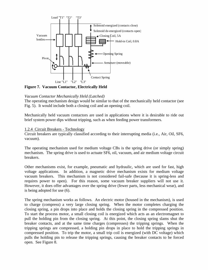
Solenoid energized (contacts close)
Solenoid de-energized (contacts open)Vacuum bottles
Contact Spring
Opening Spring
Closing Coil, 5A
PivotArmature (moveable)
Load "T1"
Line "L1"
"T2" "T3"
"L2" "L3"
Hold-in Coil, 0.8A
Figure 7. Vacuum Contactor, Electrically Held Vacuum Contactor Mechanically Held (Latched) The operating mechanism design would be similar to that of the mechanically held contactor (see Fig. 5). It would include both a closing coil and an opening coil. Mechanically held vacuum contactors are used in applications where it is desirable to ride out brief system power dips without tripping, such as when feeding power transformers. 1.2.4 Circuit Breakers - Technology Circuit breakers are typically classified according to their interrupting media (i.e., Air, Oil, SF6, vacuum). The operating mechanism used for medium voltage CBs is the spring drive (or simply spring) mechanism. The spring drive is used to actuate SF6, oil, vacuum, and air medium voltage circuit breakers. Other mechanisms exist, for example, pneumatic and hydraulic, which are used for fast, high voltage applications. In addition, a magnetic drive mechanism exists for medium voltage vacuum breakers. This mechanism is not considered fail-safe (because it is spring-less and requires power to open). For this reason, some vacuum breaker suppliers will not use it. However, it does offer advantages over the spring drive (fewer parts, less mechanical wear), and is being adopted for use (6). The spring mechanism works as follows. An electric motor (housed in the mechanism), is used to charge (compress) a very large closing spring. When the motor completes charging the closing spring, a pin drops into place and holds the closing spring in the compressed position. To start the process motor, a small closing coil is energized which acts as an electromagnet to pull the holding pin from the closing spring. At this point, the closing spring slams shut the breaker contacts, and at the same time charges (compresses) the tripping springs. When the tripping springs are compressed, a holding pin drops in place to hold the tripping springs in compressed position. To trip the motor, a small trip coil is energized (with DC voltage) which pulls the holding pin to release the tripping springs, causing the breaker contacts to be forced open. See Figure 8.

M
To Vacuum Interrupter Bottles
Charging Motor
Closing coil Tripping coil
Closing spring Tripping springsCharging ratchet
Contact spring
Holding pin
Pivot Manual mechanism torelease holding pin
Figure 8. Spring Operating mechanism for Vacuum Circuit Breaker Medium voltage CBs are always energize to trip. To design a continuously energized electromagnet to hold the breaker contacts closed against the tripping spring is not feasible. The coil would be physically too large, and would generate too much heat. For this reason, tripping coils are DC operated. Large battery banks can be used to energize these coils, even when normal AC power supply is lost. In certain applications, the tripping coil can be made AC, and supplied with a “CAP-TRIP” (capacitance trip) to energize the AC coil long enough to pull the holding pin. 1.2.5 Differences between Relay, Contactor and Circuit-Breaker (CB) Both relays and contactors can be actuated via electromagnet means (i.e., with a solenoid coil). A contactor is sometimes referred to as a “heavy-duty relay.” The circuit breaker operating mechanism also uses the electromagnetic principle, however this mechanism is much more complex and contains around 200 parts (5). Interposing relays are used in auxiliary circuits (lower voltage) as “interposing” devices to pass signals between electrical hardware, while isolating different voltage levels between the hardware. In motor control terminology, an “undervoltage trip” (or “undervoltage release”) is defined as a device that, when de-energized, is used to operate a CB to the OFF position. A “shunt trip” is defined as a device that, when energized, is used to operate a CB to the OFF position. Note that we have purposely avoided using the word relay in this context (as in undervoltage relay), due to the potential conflict with the associated protective relay function. Electrical engineers use “protective relays” to detect faults in electrical systems (including motors) and isolate the faults, by opening contactors and circuit breakers. The “protective relay” includes sensors (current and voltage transformers), a logic solver (solid state or microprocessor based), and final element (circuit breakers). Some common protective relay functions are the 46, 49, 50, and 51 (device numbers defined in IEEE Std. C37.2-2008).

Note the similarities between the protective relay and safety instrumented function, except that the former isolates a breaker due to an electrical fault, while the latter because of a process fault. The most common duty of a contactor is to switch motor loads. Circuit-breakers switch and protect medium and high voltage distribution systems by interrupting fault or short-circuit currents. Circuit-breakers are used to switch and protect low and medium voltage motors as well. Contactors are not rated to interrupt short-circuit current. A separate device (fuse or CB) must be supplied to do this function. Both contactors and CBs are used for main circuit load switching. Both will normally function closed for long periods of time and be required to pass the circuit’s normal load current. PART 2 2.0 FAILURE MODE AND MECHANISM OF BREAKERS AND CONTACTORS Contactors and circuit breakers are designed to be switched for on the order of a million operations, depending on the electrical load (3, 7). Recall our failure mode of interest for a contactor or circuit breaker is “fail to open,” typically after many years of operating closed. A contactor or breaker that is rarely switched will still “fail to open.” Further, periodic switching (v. no switching) can offer a positive maintenance benefit by actuating the mechanism. 2.1 CONTACTS - FAILURE MECHANISM The contacts of a relay, contactor, or circuit breaker are susceptible to dangerous failures (i.e., those that would make the safety instrumented function unavailable). The main reasons for contact failure are (2):
• Contact corrosion (chemical attack) • Contact erosion (mechanical wear from making and breaking) • High contact resistance • Contacts welding together
Any of the above four failure mechanisms can cause a contact to “fail to open.” For example, contact erosion will cause increased contact resistance, resulting in current heating at the reduced (by erosion) effective contact areas, causing spot welding of the contacts. When contacts “make” to complete a circuit, an arc will form between the contacts. Contact welding can occur during a “make” operation, in which the inrush current is sufficient enough for the contact material to be heated to its melting point. When the contacts touch, the molten spots will freeze, and a weld can form (3). Typically, the fact that the contacts are welded will only be discovered much later when the contacts are required to break. Arcs are formed during operation of both air switched and vacuum switched contacts, in the former case the arc is ionized air, in the latter it is metal vapor (a “vacuum arc”).
All electrical contacts weld or stick to some degree, including the contacts in a vacuum interrupter (5). Therefore, it is a desirable design feature for the operating mechanism to be able to break welded contacts, but this cannot be predicted for all welds without testing to produce a weld strength distribution. When a set of contacts in a relay weld, the remaining pairs of contacts in the same relay may or may not also stick. This is not fully predictable and is relay specific. Force-guided (mechanically linked) relays are called ‘safety relays’ because they have a predictable failure mode. It is impossible for the NO and NC contacts to closed at the same time. For example, if the NO contact is welded, the NC contact will remain open when the coil de-energizes. None of the contacts will change state, if one contact is welded. In a contactor or circuit breaker, with a large restoring force from the opening springs, the welded contact will likely break, however, the arc established across the melted contacts will not be extinguished and current will still flow (this is referred to as arc welding). If, however, the other two contacts in the contactor or breaker open successfully, the motor will stop per Kirchhoff’s current Law. 2.2 VACUUM INTERRUPTER - FAILURE MECHANISM The moving terminal of the vacuum interrupter is connected to the vacuum chamber via a stainless steel bellows. The bellows allows the moveable contact to make and break current, while still maintaining vacuum. Flexing of the stainless steel bellows during make and break operations can cause it to fail from fatigue. This results in loss of vacuum. If a vacuum interrupter tries to interrupt current with no vacuum, it will experience a severe thermal runaway event. The arc will not be extinguished and current will still flow across the contact gap. However, as above, if the other two vacuum bottles are successful in interrupting current, the motor will still stop. The electrical switching life of the vacuum interrupter (and hence vacuum contactors and vacuum circuit breakers) is limited by its mechanical life. The mechanical life is determined by the life of the bellows and separately the operating mechanism (5). Vacuum bellows are designed for tens of thousands of operations. The electrical life of the vacuum interrupter (close-open operations while switching current), is determined by the arc erosion of the contacts, and the deposit of metal on the interior walls of the ceramic container. Field data shows vacuum chambers to have mean time to failure (MTTF) values of several ten thousands of tube-years (7), while the vacuum contactor or breaker has MTTF values of several hundred years (see table 2). 2.3 OPERATING MECHANISM - FAILURE MECHANISM The operating mechanism of the relay, contactor, or circuit breaker, all rely on an electromechanical principle for means of actuation. The complexity of the mechanism increases from relay to contactor to circuit breaker. The mechanism of a contactor can cause dangerous failures several ways. For example, a weak contact spring creates poor contact force and high contact resistance, resulting in current heating

and contact welding. Also, a stuck armature would not allow the contacts to open. Or, the opening spring could be damaged, thus unable to separate the contacts. The mechanism of a CB limits its performance. The mechanical components in the mechanism are most likely to fail compared to the contacts and other electrical requirements of the breaker. Some potential dangerous failures in the CB operating mechanism are (8):
• Tripping coil not developing sufficient force. • Tripping coil burnt due to plunger stuck in tripping coil. • Problem in tripping circuit. • Mechanism linkage setting disturbed. • Various toggles and linkages sluggish or stuck.
2.4 CB - FAILURE TO INTERRUPT A circuit breaker is designed to break normal load current as well as to interrupt fault current caused by a short circuit. The failure to interrupt fault current may be classified as “failure to interrupt.” This is not a failure mode we are interested in for our protective function. PART 3 3.0 FAILURE DATA, SIF PERFORMANCE MODELING, AND IPL SELECTION When selecting a motor shutdown function to use as an IPL in a LOPA study, or when designing a SIF for the same purpose, a wide range of knowledge is required for proper application. This section discusses several of the issues and concepts involved. 3.1 FAILURE TAXONOMY When reviewing generic sourced failure data for contactors and breakers one is likely to encounter a myriad of device descriptions and failure modes. Some typical terms follow. 3.1.1 Device Classification Some terminology with explanation for classification of contactors:
• Combination Motor Starter - includes the MCCB, contactor, over-load relay, and manual disconnect all in the same enclosure (“bucket”). See Figure 1.
• NEMA Contactor/ Starter - a combination motor starter fabricated in discrete sizes to handle a certain electrical load.
• Magnetic contactor - an electrically held contactor, air switched • Vacuum contactor – utilizes vacuum technology • Low voltage - Class 600 V. Less than 1000 V. • Medium voltage - Class 5 kV and Class 15 kV. Extends up to 69 kV.
Some terminology with explanation for classification of medium voltage circuit breakers:
• MCCB - Molded Case Circuit Breaker. A type of construction using a polymer/ plastic body. Used as the CB in a combination motor starter. Not an MV device.
• Fixed - An enclosure for which a breaker is bolted or otherwise attached to the line-side bus so that it cannot be racked-out, unplugged, or otherwise removed without the use of tools. Gas Insulated Switchgear and MCCBs are considered “fixed.”

• Metal-clad - A type of medium voltage switchgear construction. Metal-clad switchgear is a draw-out type of switchgear in which the breaker is removable (can be “racked out”) to a test or disconnected position.
• Power Circuit Breakers - Generally refers to low voltage air-magnetic switchgear breakers that are of healthier construction than MCCBs, and as such can be used for longer trip delays in protective relay coordination.
• Normally Closed - When referenced in CB device descriptions, the failure data refers to a breaker that is required to open on command.
Note that metal-clad and gas insulated switchgear are not circuit-breaker types, but are used to enclose circuit breakers. The operating mechanism of the circuit breaker is typically not identified in the taxonomy of the device description for which failure data is given. However, for medium voltage applications, the spring drive mechanism is most likely used. 3.1.2 Failure Mode Classification Failure modes for contactors and circuit breakers typically include:
• All Modes • Fail to Open on Command • Fail to Close on Command • Fail to Interrupt Current
The “fail to close” on command failure mode is applicable if the safety function requires the motor to start on demand. In addition to the issues discussed here, availability of electrical power supply to the motor also has to be considered. For a circuit breaker, the “fail to interrupt current” failure mode may imply failure to interrupt fault or short-circuit current. This then would not be a failure mode we are interested in. Where the “fail to open” mode is not specified, for example, when the data is lumped into “All Modes,” it could be appropriate to assume that 20% to 40% of the lumped value represents “failure to open” (9). 3.1.3 Data for Vacuum Breakers Vacuum circuit breakers are used in both metal clad switchgear and Gas Insulated Switchgear. The spring drive operating mechanism is used for all types of medium voltage circuit breakers, including air magnetic, vacuum, and SF6. For this reason, and since failure records show the operating mechanism is the primary cause of failure for circuit breakers (10), it is possible when lacking specific data for vacuum breakers, to cite failure data from other breaker types, such as air magnetic and SF6, and other switchgear construction types, such as metal clad and gas insulated, to estimate the performance of vacuum breakers. 3.1.4 Data for Vacuum Contactors

The operating mechanism for the contactor uses the same electromechanical principle for switching in both air and vacuum. Failure data for contactors and circuit breakers is shown in Table 2. The mean time to failure (MTTF) values reported are for all failure modes. The failure data for each application should be independently verified.
DescriptionMTTF(years)
Contactor1 100 - <1000Medium Voltage Circuit Breaker2 100 - <10001. Magnetic air or vacuum type, electrically held, voltage class 600V to 15kV2. Metal Clad or Gas Insulated Construction, Air-magnetic, vacuum, or SF6, includes operating mechanism. Does not incude DC control circuit.
Source
19, 20, 21
19, 20, 21
Table 2. Failure Data for Contactors and Breakers 3.2 SAFETY INSTRUMENTED FUNCTION DESIGN (GENERAL REQUIREMENTS) Both probability of failure on demand (PFD) and hardware fault tolerance requirements (HFT) must be met when designing a SIF to meet a certain SIL target. Probability of failure on demand data analyzed for circuit breakers indicates that they are SIL 2 capable devices (17). However, there are multiple design issues that must be considered when claiming a SIL capability for a contactor or breaker. Typically, there are multiple systems that interface with a motor contactor or breaker to initiate starting and stopping. These include protective relays, starters and drives, and manual intervention. See Figure 9. However, it is a desirable design feature that the SIF be independent (physically and functionally) from these systems. This can usually be accomplished by providing an interposing relay to interface directly with the contactor or breaker operating mechanism, via the control circuit.
Load "T2"
Line "L2"
Mechanism Control Circuit (120 VAC or 125 VDC)
Protective Relay
Starter/ drives and other controllers (solid state/ microprocess based)
SIF (microprocessor based)Manual Handswitch
Contactor/ CB
Manual Break Switch
Common components shared between different shutdown methods
Line "L1"Line "L3"
Load "T1"
Load "T3"
Figure 9. Motor Control Systems that Switch Contactors and Circuit Breakers

On a project the question is often raised, can we use the protective relay device to initiate a motor trip when the safety instrumented function requires the motor to stop? Protective relays must operate on demand, and availability figures over many years of required operation, are believed to be between 95% to 99% (11). This places protective relaying performance squarely in SIL 1 range (90% to 99%). The primary limitation then for using a protective relay device in a SIL 1 safety application would be the human factors impact on the SIF performance (improper access and modification of the safety function in the protective relay). Several electrical equipment manufacturers are beginning to obtain SIL certification for devices used in low voltage motor control/ protection applications (12), and also for protective relays (13). 3.3 PROBABILITY OF FAILURE CALCULATION FOR THE PROTECTIVE FUNCTION Fault Tree analysis can be used to calculate the top event PFD representing failure of the motor to stop on demand. 3.3.1 PFD Calculation for Vacuum Contactor At a minimum, the following items should be accounted for as basic events in the fault tree: 1. Sensor 2. Logic Solver 3. Interposing relay (“Undervoltage release” - de-energize to trip) 4. Contactor (electrically held) The design should wire the AC control circuit through the NO contacts of the undervoltage coil. When the undervoltage coil is de-energized by the SIS, the NO contacts will open, de-energizing the contactor electromagnet and allowing the opening spring to break the contacts. The interposing relay and contactor are typically not credited with any automatic diagnostic capability. Manual proof-testing is required to demonstrate performance. There are no requirements for hardware fault tolerance for the interposing relay or contactor in this application (SIL 1 or 2). When composed of a high integrity logic solver, redundant field sensors, and a user-approved interposing relay and contactor, the SIF can achieve SIL 1 or SIL 2 performance, for proof-test intervals up to 3 years. Each application should be individually verified by calculation. 3.3.2 PFD Calculation for Medium Voltage Circuit-breaker At a minimum, the following items should be accounted for as basic events in the fault tree: 1. Sensor 2. Logic Solver 3. Interposing relay (“Undervoltage release” - de-energize to trip, or “Shunt trip” - energize to trip) 4. Circuit integrity of the Shunt trip (if used) 5. Circuit breaker 6. 125 VDC Control Power The 125 VDC control power is included because it is required to energize the trip coil of the circuit breaker to release the tripping spring.
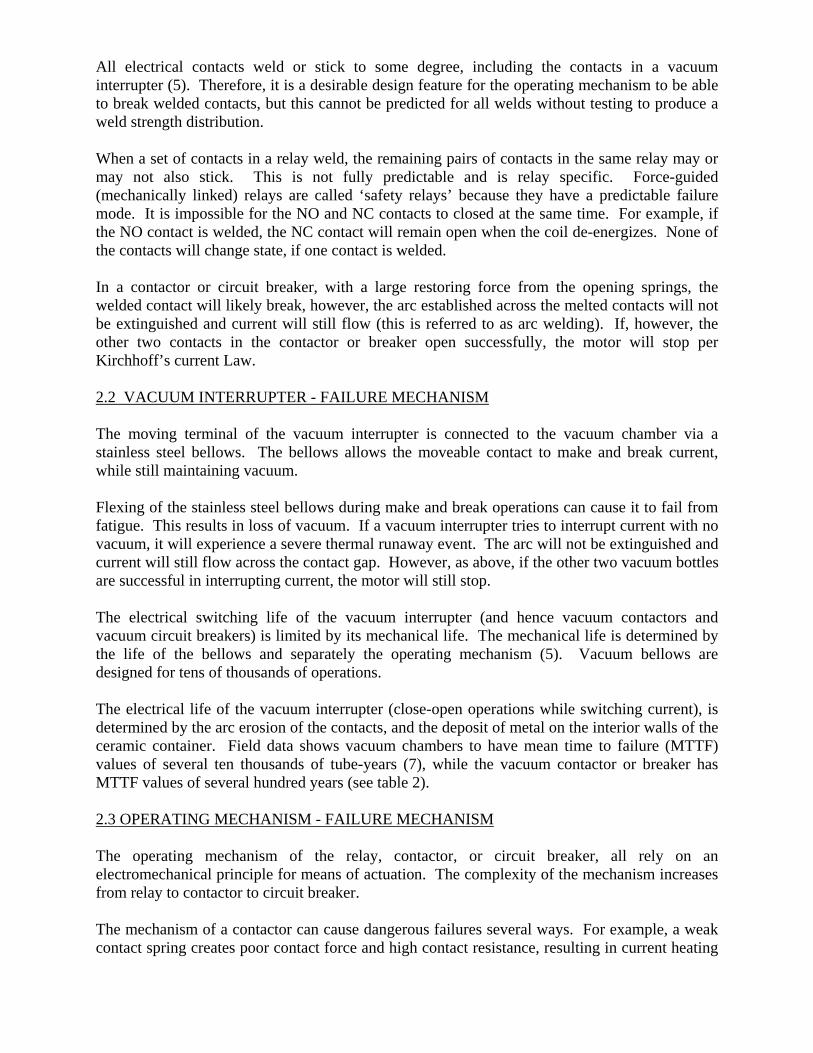
The DC control circuit uses a battery bank for redundant back-up power in the event of a main AC power failure. Main power can also be redundant from plant internal power generation backed up by public utility power. In addition, DC control power should be monitored with diagnostics and alarming provided to indicate a problem with the DC power supply. The motor protection relay can monitor the health of the DC circuitry for open wiring and blown fuses, and this needs to be alarmed as well. When all this is considered, the DC power can be considered at least as reliable as the breaker itself. Sometimes, a shunt trip is used to switch the circuit breaker, to initiate shutdown of a large electric motor. In these cases, the machine is critical to process uptime, and the desire is to reduce spurious trips of the machine, due to spurious loss of trip signal from the SIS. The design should be to wire the DC control circuit through the NO contacts of the shunt coil. When the shunt coil is energized by the SIS, the NO contacts will close, energizing the tripping coil. SIS circuit integrity and power supply should be considered in the design. Hardware fault tolerance may also need to be considered for the shunt trip circuit. If the undervoltage release is used to initiate the trip, the design should wire the DC control circuit through the NC contacts of the undervoltage coil. When the undervoltage coil is de-energized by the SIS, the NC contacts will close, energizing the tripping coil. The circuit breaker is typically not credited with any automatic diagnostic capability (however, the DC control power should be monitored and alarmed upon failure). Manual proof-testing is required to demonstrate performance. Other than for DC control power, there are no requirements for hardware fault tolerance for the interposing relay or circuit breaker in this application (undervoltage release, SIL 1 or 2). When composed of a high integrity logic solver, redundant field sensors, and a user-approved interposing relay and circuit breaker with redundant DC control power, the SIF can achieve SIL 1 or SIL 2 performance, for proof-test intervals up to 3 years. Each application should be individually verified by calculation. 3.4 INDEPENDENT SECONDARY MEANS OF SHUTDOWN, PROBABILITY CALCULATION FOR EXTENDING PROOF-TEST INTERVAL, AND MEETING SIL 3 HFT REQUIREMENTS The following are examples of when it might be necessary to consider alternate, secondary, and independent means of tripping a motor: 1. An additional IPL is required for the LOPA scenario to meet tolerable risk targets. 2. It is desired to extend proof-test intervals of the protective function, for a given SIL target requirement. 3. Meeting SIL 3 hardware fault tolerance requirements. It is noted here that this treatment is a way of demonstrating mathematically a means to extend proof-test intervals, but that other considerations should be looked at, which are not covered here. Considerations such as having actual experience that the SIF can meet its claimed PFD without the benefit of more frequent testing.

3.4.1 Using Motor Shutdown Function in LOPA It appears from Figure 9 that there are multiple means to trip a motor. The protective relay system, starters, drives, SIF, and manual action all will use a separate interposing relay to interface with the control circuit. However, these means are not independent. The DC control circuit is a point of common failure, and the contactor or breaker mechanism is another common failure point. It was discussed previously (see Section 3.2) that it would be appropriate to take 2 LOPA credits for a motor shutdown function used as an IPL. Care needs to be taken to recognize the contactor or breaker mechanism would be a common component if shared between otherwise independent devices used as IPLs for a given LOPA scenario. 3.4.2 HFT Considerations HFT can be added to most of the components in the fault tree, to improve the SIFs PFD. For example, a dual trip coil can be supplied within the circuit breaker operating mechanism to increase the chances the opening spring will be released. We have already discussed some inherent HFT with contacts, in that a single contact can fail to break current (due to welding/ arcing) but if the other two contacts open, the motor will still stop. While manual trip initiation at the mechanism itself is independent of the control circuit, it is still dependent upon the breaker functioning correctly to open the circuit. There are components within the contactor or breaker mechanism, for which it would not be feasible to make redundant. For example, the armature, holding pin, operating shaft, and other toggles and linkages. See Figure 8. The contactor or breaker mechanism then, is the limiting hardware, with respect to fault tolerance. For this reason, the following methodology is proposed, to meet IPL, HFT, or extended proof-test requirements for those cases where it is considered necessary.

3.4.3 LV Combination Motor Starter – Secondary Shutdown A second trip can be wired to the molded case circuit breaker (MCCB) to open the circuit. See Figure 10.
LV MCC (600 V Class)
M
Combination Motor Starter
120 VAC Control Circuit
Secondary Shutdown - Undervoltage trip of MCCB
Primary means of Shutdown to Open Contactor
SIS
Figure 10. Secondary Means to Trip Motor (LV MCC) This second trip path trips only the motor of interest. The MCCB should be tripped concurrently with the contactor. It does not matter from an electrical standpoint if the contactor or MCCB breaks first, since the operation is not being performed under fault (high current) conditions. The contactor and MCCB form a 1oo2 voted final element subsystem . This architecture can be used to meet HFT requirements or extend proof-test intervals. Common cause failure can be considered between the contactor and breaker, but because diverse technology is used, it will be minimal (18). 3.4.4 MV Contactor or Circuit Breaker – Secondary Shutdown An upstream breaker can be tripped if the contactor or circuit breaker dedicated to the motor fails to open. See Figures 11 and 12.

MV MCC (5 kV Class)
M
49
Motor Starter/ Controller)
120 VAC Control Circuit
Protective Relay
Primary means of Shutdown to Open Contactor
52 125 VDC Control Circuit
Secondary Independent Shutdown to Open CB
Identify any Secondary Hazards created by Opening Upstream '52' CB
Other Process Equipment
SIS
Operator Intervention
As needed
Figure 11. Secondary Means to Trip Motor (MV MCC) There are caveats associated with this option, namely making sure the process hazard analysis includes identification of any secondary consequences from tripping the upstream breaker.
52
MV Metal Clad SWGR (15 kV Class)
M
49 Protective Relay
125 VDC Control Circuit
52 125 VDC Control Circuit
Secondary Independent Shutdown to Open CB
Primary means of Shutdown to Open CB
Other Process Equipment
Identify any Secondary Hazards created by Opening Upstream '52' CB
SIS
Operator Intervention
As needed
Figure 12. Secondary Means to Trip Motor (MV Switchgear) The justification for this method is that it is analogous to the back-up action of a protective relay. Protective relays are zoned and coordinated so that the relay closest to the fault isolates first, and only a minimum amount of equipment is removed from service in the event of fault isolation. If the first relay cannot isolate the electrical fault, a relay upstream of the first will operate, isolating the fault and removing much more equipment from service. Breaker failure protection schemes that utilize local back-up are already provided for major power systems (14). One such

back-up protective relay scheme has been used to claim SIL capability for a digital relay system (one that is microprocessor based) (13). The most appropriate application for this action would be as an addition IPL to claim during a LOPA study. The IPL would include: a command disagree alarm (indicating the breaker failed to open/ the motor failed to stop) with operator intervention to trip the upstream breaker. Normal IPL rules apply. Written procedure, training, and auditing of the action are required. There must also be sufficient process safety time for operator intervention. If tripping the upstream breaker is automated from the safety system (no human action), then credit for HFT or extending proof-test intervals is applicable. PART 4 4.0 MECHANICAL INTEGRITY OF BREAKERS AND CONTACTORS The mechanical integrity of the contactor or circuit breaker must be maintained for the life of the installation to ensure performance expectations are maintained. For purposes of estimating SIF performance, it is important that the equipment used to perform the safety function be maintained “as good as new,” so that failure rates can be assumed constant, and not increasing as when a device is in the wear-out region of the bath tube curve. 4.1 OPERATIONAL PERFORMANCE Circuit breakers result in the most frequent failures in metal clad and gas insulated switchgear (15). Aging failures caused by decrease in mechanical or electrical strength have been found as the major cause of failure (90%) compared to 10% random failure for circuit breakers. This points to the relevance of inspection, testing, and preventive maintenance of switchgear, including circuit breakers. Switchgear is subject to wear-out processes such as material fatigue under cyclic load, vibration, and severe forces under fault interrupting conditions. Electromechanical control and protection devices are subject to similar stresses and also deteriorate rapidly at the end of their useful lives. One failure study has estimated the expected average lifetime of circuit breakers to be 30 years, where the probability density function is high and narrow at this point (15). The same study showed failure rates for circuit breakers to be constant for about 20 years, after which they begin to enter the wear-out portion of the bathtub curve, where a steep increase in failure rate is observed. 4.2 GENERAL MI REQUIREMENTS CCPS (16) recommends mechanical integrity activities for switchgear. Calibration and testing of protective relays and tripping associated circuit breakers is recommended every 3 to 6 years, depending on electrical load. Inspection, maintenance, and testing of Air and Oil Circuit Breakers is recommended every 3 years (maximum). Vacuum Circuit Breakers should be tested and maintained per manufacturer’s recommendations. Some CB spring mechanisms are maintained with lubricating oil (8). Lubricating points include bearings, sliding surfaces, levers, connecting joints, and rollers.

Modern vacuum interrupter bottles are considered “maintenance free.” The contacts require no maintenance for the life of the vacuum interrupter (5, 7). It has been demonstrated that the vacuum interrupter will operate successfully even after years of non-operation (5). For these reasons, vacuum contactors and breakers may have recommended inspection and test intervals of five years or longer. PART 5 5.0 SUMMARY Contactors and circuit breakers are used as final element subsystems in safety instrumented functions and in independent protection layers, to switch current to stop electric motor driven machinery. Vacuum interrupter technology has become the technology of choice for medium voltage motor switching applications. Low voltage applications typically use magnetic contactors switched in air. Both contactors and circuit breakers can exhibit dangerous failures. For vacuum technology, the dangerous failure is most likely to occur in the operating mechanism of the contactor or breaker. This applies to magnetic contactors as well, which utilize the same electromechanical principle of operation. Contactors (vacuum and magnetic) utilize strong electromagnets for running, and thus are fail-safe with respect to control power. Circuit breakers are mechanically latched for running, and require an energized tripping coil to open the breaker. Generic failure data records and probability calculations show that SIL 2 performance is achievable by contactors and breakers when they are tested and maintained. It would be appropriate to use two LOPA credits (PFD = 0.01) for a LOPA scenario, if the other devices in the same IPL support that. For meeting SIL 3 HFT requirements, or if extending the proof-test interval is desired, it is necessary (for MV applications) to look at secondary means of de-energization from an upstream breaker, analogous to protective relaying philosophy. For LV applications, the MCCB can be tripped in addition to the contactor, to meet HFT requirements or extend proof-testing. Contactors and breakers should be included in the facility’s mechanical integrity program.

5.1 REFERENCES (1) CEP (Chemical Engineering Progress), Process Safety Beacon -What is a Safety Instrumented System?, July 2009. (2) Gayford, M.L., Modern Relay Techniques, STC Monograph No 1, Newnes-Butterworths, 1969. (3) Paul G. Slade (Editor), Electrical Contacts: Principles and Applications, Marcel Dekker, 1999. (4) Walter N. Alerich and Stephen L. Herman, Electric Motor Control, 7th Ed, Thomson Delmar Learning, 2003. (5) Paul G. Slade, The Vacuum Interrupter - Theory, Design, and Application, CRC Press 2008. (6) Dr. Alexey Chaly, H. Rebstock, V. Poluyanov, V. Zakharov, Most Relevant Results from Research and Development in the Field of Medium Voltage Vacuum Circuit Breakers - A Review, 2006 China International Conference on Electricity Distribution, Sept. 2006, Beijing. (7) H. Fink and R. Renz, Future Trends in Vacuum Technology Applications, 20th ISDEIV International Symposium on Discharger and Electrical Insulation in Vacuum, 2002. (8) BHEL (Bharat Heavy Electricals Limited), Handbook of Switchgears, McGraw-Hill, 2007. (9) RiAC (Reliability Information Analysis Center), FMD-97. (10) Bartosz Rusek, G. Balzer, M. Holstein, M. Claessens, Timings of High Voltage Circuit-Breaker, Electric Power Systems Research 78 (2008) (11) J. Lewis Blackburn and Thomas J. Domin, Protective Relaying: Principles and Applications, 3rd Edition, CRC Press, 2007. (12) Bas Bouman, et al., SIL Classification for Intelligent Motor Control Systems in Accordance with the ATEX Directive, 5th Petroleum and Chemical Industry Conference Europe - Electrical and Instrumentation Applications, 2008. (13) Franck Gruffaz and Jean Pierre Signoret, SIL Rated Protection Digital Relays meet IEC 61508 Safety Requirements without Lowering Process Availability, 2nd European Conference on Electrical and Instrumentation Applications in the Petroleum and Chemical Industry, Basle, October 2005. (14) V. Muthukrishnan, T.S. Sidhu, Fast and Secure Breaker Failure Detection Algorithms, IET Generation, Transmission & Distribution, Vol. 3, Iss. 2, 2009. (15) Xiang Zhang, E. Gockenbach, V. Wasserberg, H. Borsi, Estimation of the Lifetime of the Electrical Components in Distribution Networks, IEEE Transactions on Power Delivery, Vol. 22, No. 1, January 2007. (16) CCPS (Center for Chemical Process Safety), Guidelines for Mechanical Integrity Systems, 2006. (17) CCPS (Center for Chemical Process Safety), Guidelines for Process Equipment Reliability Data, 1989. (18) D.M. Rasmuson, A. Mosleh, T.E. Wierman, Insights from Analyzing the Nuclear Regulatory Commission’s Common-Cause Failure Database, Proc. IMechE Vol. 222 Part O: Journal of Risk and Reliability, 2008. (19) RiAC (Reliability Information Analysis Center), NPRD-95. (20) IEEE Std 500-1984 (21) IEEE Std 493-2007