Embed Size (px)
Citation preview
safety performance cleanup closureME Environmental ManagementEnvironmental Management
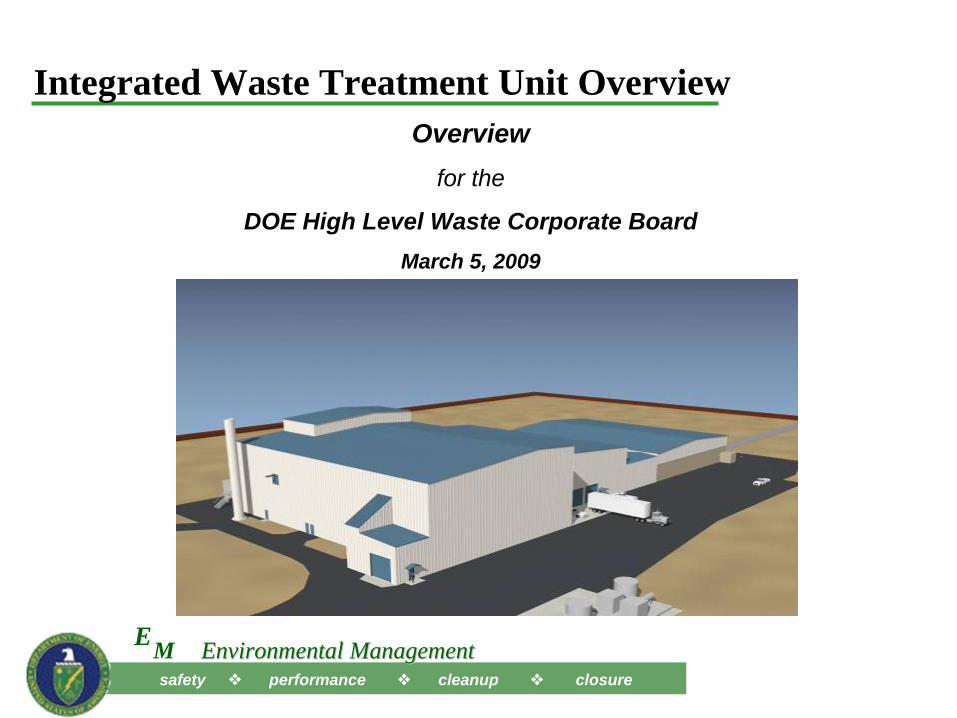
Integrated Waste Treatment Unit OverviewOverview
for the
DOE High Level Waste Corporate BoardMarch 5, 2009
safety performance cleanup closureME Environmental ManagementEnvironmental Management
22
Integrated Waste Treatment Unit Mission
• Mission– Project mission is to provide treatment of approximately 900,000 gallons of
tank farm waste – referred to as sodium bearing waste (SBW) - stored at the Idaho Tank Farm Facility to a stable waste form suitable for disposition at the Waste Isolation Pilot Plant (WIPP).
– Per the Idaho Cleanup Project contract, the resident Integrated Waste Treatment Unit (IWTU) facility, shall have the capability for future packaging and shipping of the existing high level waste (HLW) calcine to the geologic repository.
safety performance cleanup closureME Environmental ManagementEnvironmental Management
33
IWTU Process Description
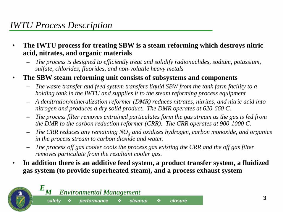
• The IWTU process for treating SBW is a steam reforming which destroys nitric acid, nitrates, and organic materials
– The process is designed to efficiently treat and solidify radionuclides, sodium, potassium, sulfate, chlorides, fluorides, and non-volatile heavy metals
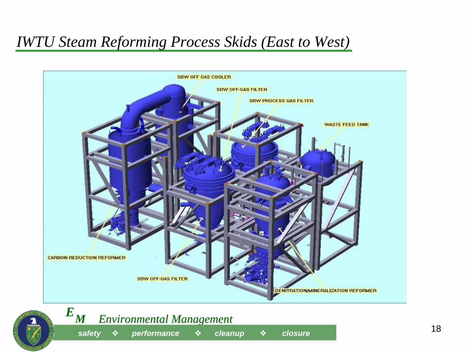
• The SBW steam reforming unit consists of subsystems and components– The waste transfer and feed system transfers liquid SBW from the tank farm facility to a
holding tank in the IWTU and supplies it to the steam reforming process equipment– A denitration/mineralization reformer (DMR) reduces nitrates, nitrites, and nitric acid into
nitrogen and produces a dry solid product. The DMR operates at 620-660 C.– The process filter removes entrained particulates form the gas stream as the gas is fed from
the DMR to the carbon reduction reformer (CRR). The CRR operates at 900-1000 C.– The CRR reduces any remaining NOX and oxidizes hydrogen, carbon monoxide, and organics
in the process stream to carbon dioxide and water.– The process off gas cooler cools the process gas existing the CRR and the off gas filter
removes particulate from the resultant cooler gas.• In addition there is an additive feed system, a product transfer system, a fluidized
gas system (to provide superheated steam), and a process exhaust system
safety performance cleanup closureME Environmental ManagementEnvironmental Management
4
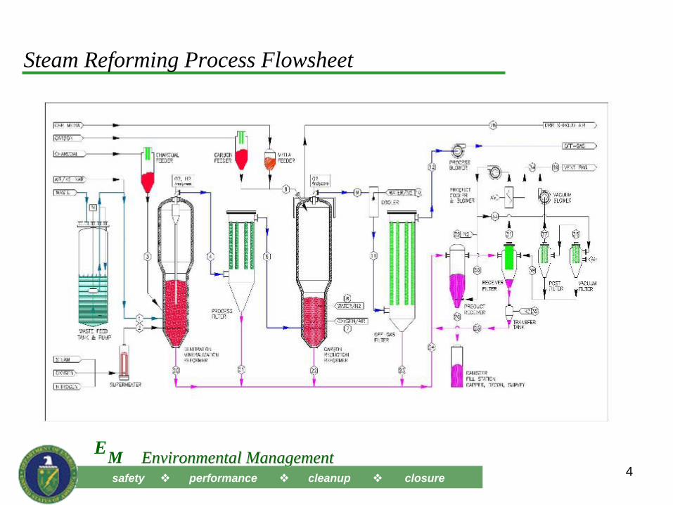
Steam Reforming Process Flowsheet
safety performance cleanup closureME Environmental ManagementEnvironmental Management
5
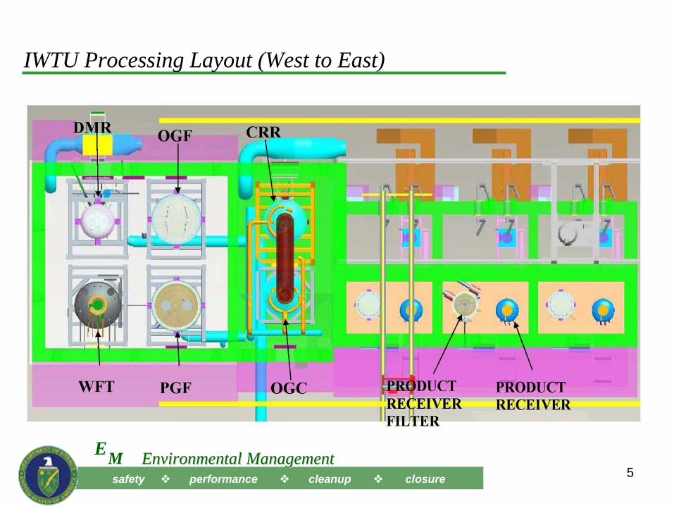
IWTU Processing Layout (West to East)
safety performance cleanup closureME Environmental ManagementEnvironmental Management
6
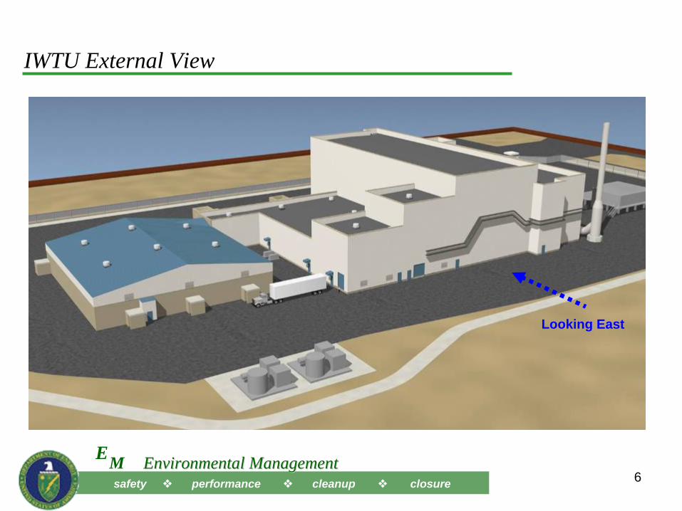
IWTU External View
Looking East
safety performance cleanup closureME Environmental ManagementEnvironmental Management
9
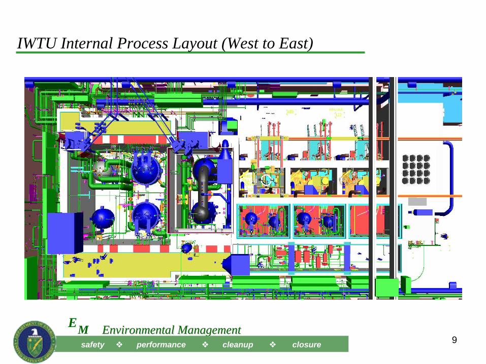
IWTU Internal Process Layout (West to East)
safety performance cleanup closureME Environmental ManagementEnvironmental Management
10
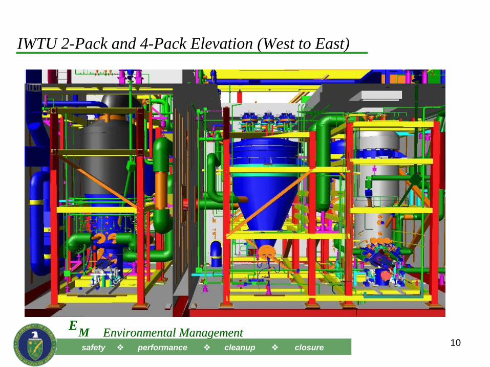
IWTU 2-Pack and 4-Pack Elevation (West to East)
safety performance cleanup closureME Environmental ManagementEnvironmental Management
11
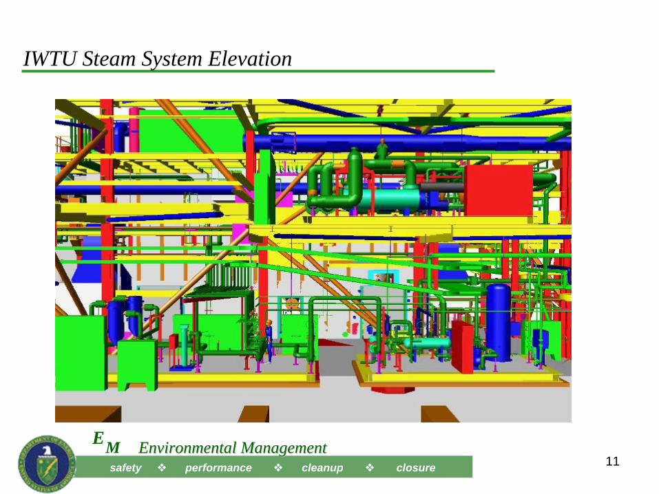
IWTU Steam System Elevation
safety performance cleanup closureME Environmental ManagementEnvironmental Management
12
Sodium Bearing Waste (SBW) Origin
• The SBW is comprised mainly of 900,000 gallons of tank waste remaining after calcination ceased in 2000.
• It is a comprised of a mixture of:– Decontamination solutions from cleanup of equipment and facilities– Laboratory wastes – Spent fuel basin water treatment discharges, off-gas cleanup scrub solutions,
condensate from tank farm transfer equipment, contaminated facility sump water, and other low activity miscellaneous plant wastes
– Tank heel solids– Some 2nd and 3rd cycle raffinate from reprocessing– Small volume (~1%) of 1st cycle raffinate from reuse of HLW tanks for SBW
storage without removing all tank bottoms
safety performance cleanup closureME Environmental ManagementEnvironmental Management
1414
SBW Project Description
• IWTU steam reforming technology converts acidic radioactive liquid waste to solid carbonate particles
– Design process rate ~ 3.1 GPM; operating process rate ~ 2 GPM (24/7 with 65% plant availability) = 0.9-2.4 canisters per day (673 canisters total)
• Produces about 650 (10’x 2’ dia.) remote-handled TRU waste canisters– Product is about 50 R on contact
• The Process Building includes Performance Category 3 (PC-3) reinforced concrete process cells
– Upgraded from PC-2 mainly to support a potential future (higher source term) calcine mission
– Calcine is about 500 R on contact
• The Product Storage Building provides interim storage capacity (704 positions) for entire carbonate product volume
– 44 vaults with 16 positions each = 704 canisters
safety performance cleanup closureME Environmental ManagementEnvironmental Management
15
SBW Product Waste Form• Baseline flowsheet produces a carbonate waste form
– Suitable for disposal at WIPP as a remote-handled transuranic waste
• WIPP permit currently prohibits receipt and disposal of treated tank waste from Idaho without a Class III permit modification
– SBW includes a small volume of co-mingled reprocessing waste– A permit modification request is assumed to require some type of waste
determination to conclude the waste is transuranic and not high-level waste
• Shipping/Disposal has been removed from the current contract scope pending a disposal decision
• Risk Mitigation for the project includes designing and constructing the facility so that it could be converted to treat the waste for alternate disposal as HLW at Yucca Mountain, if needed
safety performance cleanup closureME Environmental ManagementEnvironmental Management
16
Defense Nuclear Facilities Safety Board - Areas of Interest• Seismic/Structural Design Adequacy
– Additional geotechnical investigation– Extensive reviews of seismic inputs and structural analyses
• Pilot Plant Testing– Testing at the Hazen Research Inc. facility (Golden, Colorado) was performed
to evaluate safety aspects of the flow sheet– Over-temperature event occurred during testing in charcoal adsorber bed
• Required investigation and preventative process controls
• Waste Characterization– Further characterization was needed to validate safety basis assumptions– Additional sampling data compiled and analyzed
• Concerns over adequacy of Distributed Control System Design– Design now separates safety-related control functions from other process
controls– Incorporated ANSI/ISA Standard 84.00.01, Safety Instrumented Systems for the
Process Industry Sector
Project Cost and Schedule Changes
• Major changes to project scope/schedule since contract award
– One-year delay in hot startup directed by DOE to level funding requirements in three main areas
• To accommodate commodity growth and price increases• To accommodate design/construction impact of seismic design changes• To maintain funding of D&D and buries waste retrieval activities
pursuant to the settlement with the state of Idaho
• Baseline Change approved January 2009– Increased total project cost from $461 M to $571 M– Delayed hot startup from July 2010 to August 2011
• Project still on target to meet SA completion of “calcining” date of December 31, 2012
17
safety performance cleanup closureME Environmental ManagementEnvironmental Management
18
IWTU Steam Reforming Process Skids (East to West)
safety performance cleanup closureME Environmental ManagementEnvironmental Management
19
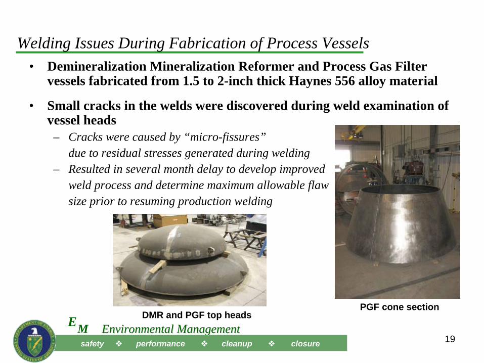
Welding Issues During Fabrication of Process Vessels• Demineralization Mineralization Reformer and Process Gas Filter
vessels fabricated from 1.5 to 2-inch thick Haynes 556 alloy material
• Small cracks in the welds were discovered during weld examination of vessel heads
– Cracks were caused by “micro-fissures”due to residual stresses generated during welding
– Resulted in several month delay to develop improved weld process and determine maximum allowable flaw size prior to resuming production welding
PGF cone sectionDMR and PGF top heads
safety performance cleanup closureME Environmental ManagementEnvironmental Management
21
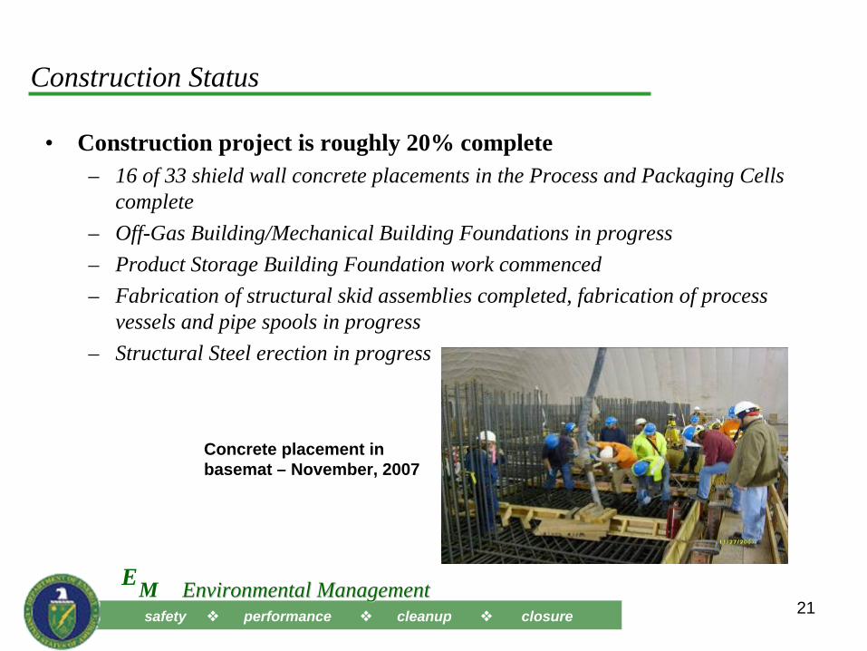
Construction Status
• Construction project is roughly 20% complete– 16 of 33 shield wall concrete placements in the Process and Packaging Cells
complete– Off-Gas Building/Mechanical Building Foundations in progress– Product Storage Building Foundation work commenced– Fabrication of structural skid assemblies completed, fabrication of process
vessels and pipe spools in progress – Structural Steel erection in progress
Concrete placement in basemat – November, 2007
safety performance cleanup closureME Environmental ManagementEnvironmental Management
22
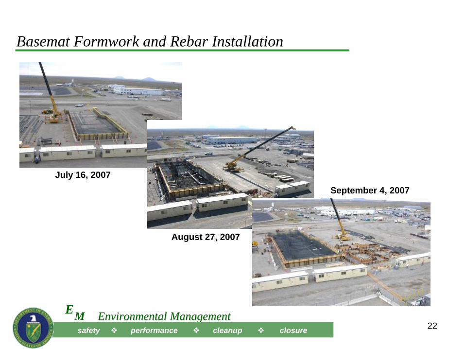
Basemat Formwork and Rebar Installation
July 16, 2007
August 27, 2007
September 4, 2007
safety performance cleanup closureME Environmental ManagementEnvironmental Management
23
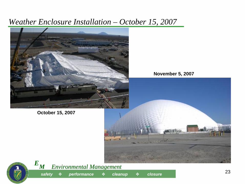
Weather Enclosure Installation – October 15, 2007
October 15, 2007
November 5, 2007
safety performance cleanup closureME Environmental ManagementEnvironmental Management
24
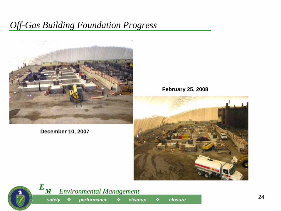
Off-Gas Building Foundation Progress
February 25, 2008
December 10, 2007
safety performance cleanup closureME Environmental ManagementEnvironmental Management
25
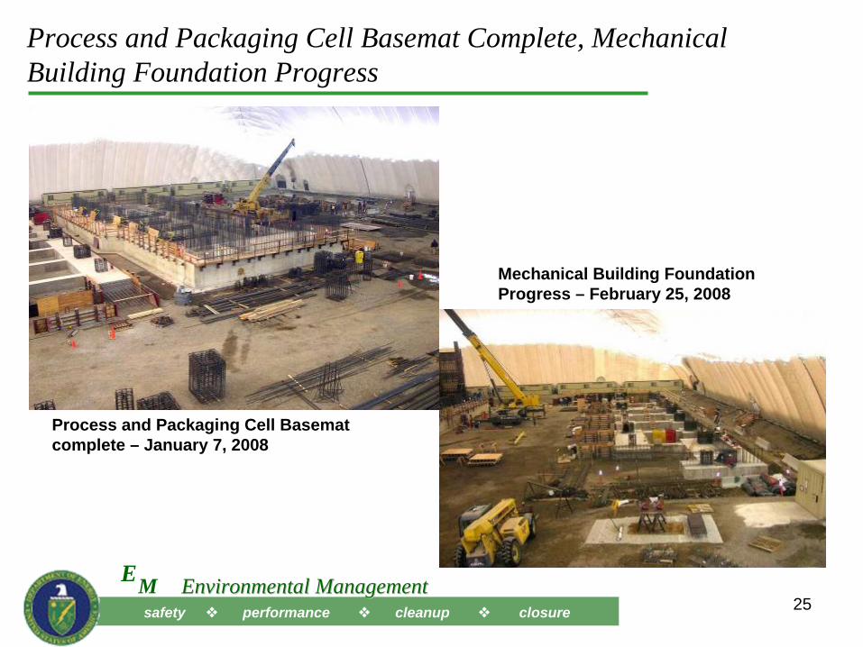
Process and Packaging Cell Basemat Complete, Mechanical Building Foundation Progress
Process and Packaging Cell Basemat complete – January 7, 2008
Mechanical Building Foundation Progress – February 25, 2008
safety performance cleanup closureME Environmental ManagementEnvironmental Management
26
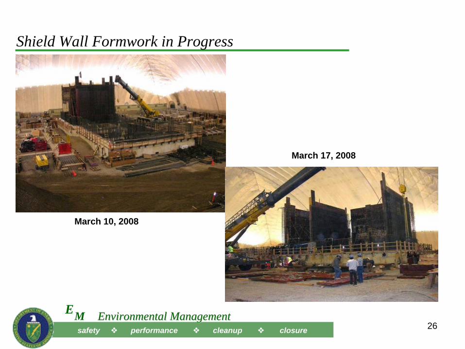
Shield Wall Formwork in Progress
March 10, 2008
March 17, 2008
safety performance cleanup closureME Environmental ManagementEnvironmental Management
27
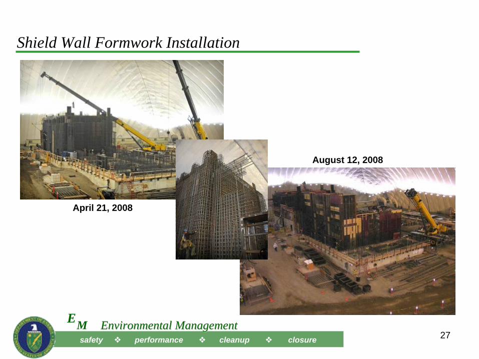
Shield Wall Formwork Installation
April 21, 2008
August 12, 2008
safety performance cleanup closureME Environmental ManagementEnvironmental Management
28
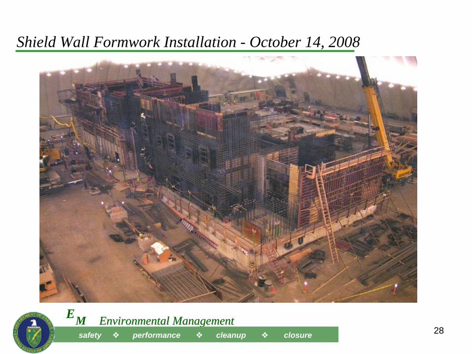
Shield Wall Formwork Installation - October 14, 2008
safety performance cleanup closureME Environmental ManagementEnvironmental Management
29
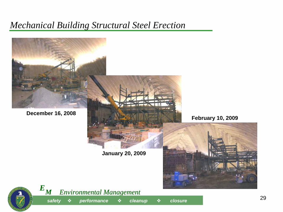
Mechanical Building Structural Steel Erection
December 16, 2008
January 20, 2009
February 10, 2009
safety performance cleanup closureME Environmental ManagementEnvironmental Management
30
IWTU Future Mission Potential
• Facility design includes consideration of future packaging and load-out compatibility with existing calcine waste
• Risk mitigation for the project also includes designing and constructing the facility so that it could be converted for calcine treatment if necessary
• Required change from PC-2 to PC-3 resulted in significantly higher design loadings and associated analysis, physically resulting in:– Enlargement of the process cell mat foundation (thickness and footprint),– Thickening of the process cell walls,– Changes from steel plate to concrete on some of the process cell walls,– Addition of strip footers (i.e., tie-beams) in the foundations under the process
building,– An increased number of columns in the process building to support building
size increase, and– Significant structural bracing growth.
safety performance cleanup closureME Environmental ManagementEnvironmental Management
33
Backup Slides
safety performance cleanup closureME Environmental ManagementEnvironmental Management
34
Genesis of Project
• Tank waste was generated directly and indirectly from spent fuel reprocessing
– Was historically converted to a solid particulate waste form by a fluidized-bed calcination process (1963 – 2000)
• Calcination process operated efficiently for majority of 7-8 million gallons of 1st cycle raffinate reprocessing waste
– Reprocessing was discontinued in 1991
• Other wastes of much lower radioactivity (2nd and 3rd cycle raffinate wastes, decontamination wastes, and other ancillary wastes) were stored together
– This mixture of other wastes was more difficult to calcine, due to the relatively high levels of sodium from decontamination chemicals
– These wastes are referred to as sodium bearing wastes (SBW)• Some SBW was blended in low volumes (less than 10%) with 1st cycle wastes
during calcination
safety performance cleanup closureME Environmental ManagementEnvironmental Management
35
Genesis of Project (Continued)
• In the early 1990’s, regulatory issues surfaced with the tank farm tanks and with operation of the calcination process.
– Single shell stainless steel (300,000 gallon) tanks enclosed in concrete vaults do not meet RCRA double containment requirements for acidic waste
– The New Waste Calciner Facility was operated under a RCRA Part A permit and did not meet MACT criteria
• A 1995 Idaho Settlement Agreement requires completion of calcination of the reprocessing wastes by 2012 (tanks out of service)
• Preparation of the Idaho High-Level Waste and Facilities Disposition (HLW&FD) Environmental Impact Statement (EIS) commences in 1997,
– Evaluated several treatment alternatives for treatment of reprocessing wastes
• In compliance with regulatory commitments, the calcination process was placed in a shutdown condition in May 2000 awaiting final treatment technology decisions.
safety performance cleanup closureME Environmental ManagementEnvironmental Management
36
Genesis of Project (Continued)
• CWI was awarded the Idaho Cleanup Project in May 2005, which included treatment of sodium bearing waste.
– CWI proposed steam reforming as the treatment technology for treatment of the sodium bearing waste
• With issuance of the HLW&FD EIS in 2002, DOE announced in August 2005 that steam reforming was the preferred treatment technology
• DOE Record of Decision was published in December 2005 selecting steam reforming as the treatment technology for sodium bearing waste
safety performance cleanup closureME Environmental ManagementEnvironmental Management
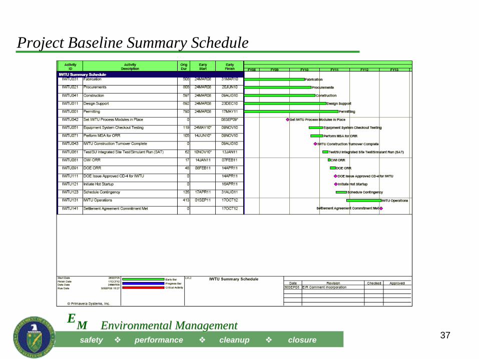
37
Project Baseline Summary Schedule