Embed Size (px)
Citation preview

2012 SIMULIA Community Conference 1
Integrated Simulation Data and Process Management System for Virtual Tire Development
using SIMULIA SLM
Young-soo Yoon, Hye-jeong Yu, Hans Baek, Joo-hwan Kim,
Joo-bae Park, Sang-joo Lee
Hankook Tire
Frederic Merceron, Dong-min Jang
SIMULIA
Abstract: Manufacturing companies use CAE simulations for validation tools in the early product
design stage in order to shorten product development cycle. But engineering simulations are
considered to be usable by only experts. This is why Hankook Tire has implemented a lot of task
automation regarding CAE simulations. Consequently these automations help Hankook Tire to
improve tire design with better qualities, less physical tests and reduce product costs.
However most of implementations on simulation automations mainly focus on process automation
and not on CAE data management. Moreover these automation systems did not support PLM
integration. If some relevant information between tire development and CAE simulation were
needed, then it was done manually not via an integrated IT system. Thus Hankook Tire started to
have a plan to implement an integrated CAE process and data management system which supports
PLM interface.
The solution is called “Virtual Engineering Central System (VECS)” and Dassault Systèmes
Simulation Lifecycle Management (SLM) has been used to host the automation of processes and
manage the lifecycle of CAE data. Hankook Tire and SIMULIA engaged on a SLM strategic
partnership to transform the way the simulation processes were used inside the company.
Hankook Tire experts developed advanced simulation processes and customized system; the
objective is to provide an analysis portal to increase their usage through a larger community.
SLM has been used to host the automation of the processes and manage the lifecycle of the data
used and generated. The expected benefits were to improve the capability to assess the
performance of the tires, and standardize on simulation practices to increase the capitalization
and the reuse.
This report will describe the initial objectives, the implementation experience and the results
obtained.
Keywords: SIMULIA SLM, CAE, Tire, PLM, Virtual Testing, Engineering Process, Data
Management, HPC
2 2012 SIMULIA Community Conference
1. Introduction
1.1 Background
In order to get more competitive among manufacturing business, shortening product development
time with lower costs has been emphasized. When a preliminary design product is built and tested
for performance validations, a lot of costs and time is spent. Therefore reducing prototype and
physical testing at early stages of product design are common requirements for manufacturing
industries. Virtual simulation is considered as one of the solutions for performance validation
with less physical testing.
Hankook Tire also has utilized simulation results for tire design processes. And the scope of
simulation is getting expanded. However most of simulation executions and reviews are
performed by tire simulation experts and not designers. And a lot of time and resources should be
used for Finite Element Analysis procedures such as pre-processing, solving, post-processing and
results reviewing for a simulation report. If a design change takes place following a change
request of a designer, the performance validation via simulation should be requested to an expert
and it takes time. Sometimes this kind of validation procedure could not be completed within due
date.
Therefore simulation automations have been studied and implemented by Hankook Tire R&D
resources. These implementations helped tire designers to execute basic simulations and utilize
the simulation results for tire design validations. All GUI and terminologies are easy to
understand for designers and learning curve was quite short. Via automatic simulation executions,
simulations are exposed to more designers and relevant engineers.
1.2 Business Challenges
Most of simulation automations have been done on process automation but not on simulation data
management. As simulation activities are getting larger, relevant simulation results such as large
size raw results, extracted key results and reports are accumulated without particular order. For a
single user recent simulation data can be searched and traced but old data and other’s data are
difficult to reuse for collaboration. Actually a lot of efforts should be spent for data aggregation
and traceability.
Nowadays having multi-site R&D centers globally is necessary in global business environments
and collaboration is emphasized more and more. In terms of PLM (Product Lifecycle
Management), product data, development processes and projects are managed with collaboration
functions in the enterprise level. Simulation data information also should be referenced within the
PLM for collaborations in the context of “what-if” study. Unfortunately most of implementations
regarding simulation automations for Hankook Tire lacked some capabilities to interface with
PLM enterprise solutions.
Therefore, we needed the integrated simulation environment that can effectively manage the data,
process and knowledge. It should help engineers get the latest and accurate information to support
decision activities for a new product design in conjunction with the development process of the
PLM system. We named this integrated simulation environment as "Virtual Engineering Central
System (VECS)" and have engaged a strategic partnership with Dassault Systèmes SIMULIA to

2012 SIMULIA Community Conference 3
transform way of the simulation processes are used in the company. We expect VECS will help
Hankook Tire to enhance collaboration within the enterprise and to increase the productivity.
1.3 Reason for selection of Dassault Systèmes SLM Solution
To construct VECS, we examined commercial solutions provided from several leading vendors in
this field, and finally we selected the SLM solution of Dassault Systèmes SIMULIA. Our
company uses Matrix One (currently ENOVIA) as a PLM solution and we considered important
the integration between the product data/the development process of PLM system and simulation
data. If we adopt the other solutions, we would have to implement the system in the new
environment and framework because the environment of our PLM solution (Matrix One) is
different from the other company's solutions, and we would have to maintain both systems. In
addition, the other solutions can't directly access the PLM resource, so we would spend a lot of
implementation time and costs because we would have to develop an additional program that can
access the PLM resource. In contrast, the SLM solution of Dassault Systèmes SIMULIA is an
ENOVIA central (Simulation central), so it was possible to use the previous PLM framework. As
they are on the same framework, there is no need to worry about accessing to the PLM resource.
Maintenance is also easy because it is operated in a single system.
Hankook Tire has used various kinds of simulation tools and ABAQUS has been primarily used as
the tire FE tool. Some tire performance simulation processes were automated through the
construction of the simulation automation system, and many post-processing programs have been
developed with python-based ABAQUS scripts. According to Dassault Systèmes SIMULIA
product portfolio, SLM is supposed to understand the execution process and the post-processing of
ABAQUS well, so we concluded that there is no problem to use the existing process and post-
processing program developed by us. In addition, the SLM solution supports not only the
ABAQUS but also the other simulation tools and in-house tools via simulation application
connectors.
Finally, Dassault Systèmes has released the V6 environment. In the V6 environment, the CATIA
is linked to the ENOVIA. It means that all design data and information of the CATIA are managed
in ENOVIA. As a single source of truth, the V6 environment seems to be more flexible and
convenient to implement an integrated simulation system. Currently we are using CATIA V5, but
we are considering using CATIA V6 according to environment changes in the future. Therefore,
we adopted the SLM solution of Dassault Systèmes SIMULIA that is the most suitable solution
for our IT infrastructure and functional aspects.
4 2012 SIMULIA Community Conference
2. What is SLM?
Prior to describe VECS, we needed to check the SLM solution of Dassault Systèmes SIMULIA as
a basis for the construction of VECS. SLM was initially the name of a product , but the term SLM
might be understood as a general term like as PLM. Now SLM is a solution packages for
simulation lifecycle management by Dassault Systèmes SIMULIA. SLM solution consists of the
following.
2.1 SIMULIA Scenario Definition (SCE)
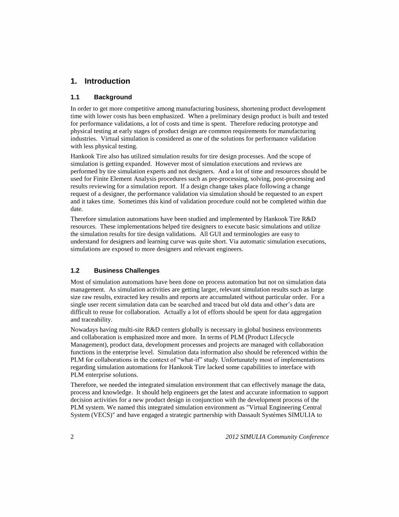
SIMULIA Scenario Definition (formerly SLM) is a tool for managing the files and data associated
to simulate a real-world process.(Figure 1) SIMULIA Scenario Definition allows you to manage
the data and to understand where you are in the simulation process and how you need to proceed.
SIMULIA Scenario Definition also provides an interface to the applications that are used in a
simulation, such as CAD packages, finite element solvers, image generating tools, and in-house
scripts and utilities. SIMULIA Scenario Definition extends traditional Product Lifecycle
Management (PLM) concepts by providing capabilities that are specific to simulations and tools
that create and execute realistic simulations.
The main concepts are:
Simulation Process/Simulation Activity.
A simulation process contains the data and processes that reproduce the scenario you are
trying to simulate. Simulation activities are the steps necessary to perform a simulation
process. Simulation processes use simulation activities to run external applications, such
as Abaqus/Standard and Acusolve and to move data between SIMULIA Scenario
Definition and the application.
Simulation Template
Templates allow the Simulation Methods Developers in an organization to capture the
best practices and intellectual property that are encapsulated in a well-designed
simulation process or simulation activity. The organization can then use the same
templates to disseminate the information encapsulated by the simulation process or
activity to a variety of SIMULIA Scenario Definition analysts.
Simulation Document
Documents contain one or more files. Documents can be either owned or referenced, and
the files within a document can be either versioned or non-versioned.
Export/Import Rules
Export rules : Moves documents from SCE database into the working directory.
Import rules : Moves files generated by the application from the working directory into
documents in SCE database.
Host/Connector
Host : The machines that can execute the applications defined in connectors.
2012 SIMULIA Community Conference 5
Application connectors allow you to execute external applications from within SCE.
Figure 1. Data and Process Management in SCE
2.2 SIMULIA Execution Engine
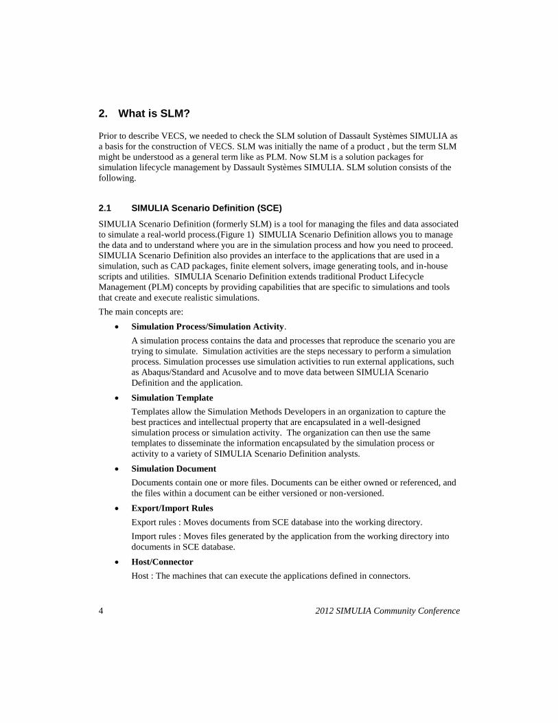
Execution Engine Application Server
Execution Engine Application Server manages the internal operations of the system,
including interaction with middleware application servers, databases, and distributed
resource management systems in align with SCE (Figure 2.). It also supports job
dispatching, job queues, time-controlled execution and load management of jobs. Parallel
processing jobs can be specified to execute in parallel automatically to leverage computer
resources. Secure credential management support for the applications in the simulation
process flow.
Stations
Stations are computers that have been registered as hosts that are eligible to run jobs sent
by the Execution Engine Application Server in a heterogeneous, distributed environment.
Isight - Automated Simulation Process Flow Authoring
Create flexible simulation process flows, consisting of a variety of models and
applications, in order to define, capture, and automate ad-hoc and standardized simulation
methods. Propagates reliable, repeatable simulation methods throughout the organization
within a managed environment designed for continuous improvement and innovation.

6 2012 SIMULIA Community Conference
Figure 2. Management of Workflows and Execution Resources
3. Virtual Engineering Central System (VECS)
In order to enable the engineering knowledge managed and reused in the enterprise system,
Hankook Tire has implemented a SLM system named VECS. A reliable SLM system cannot be
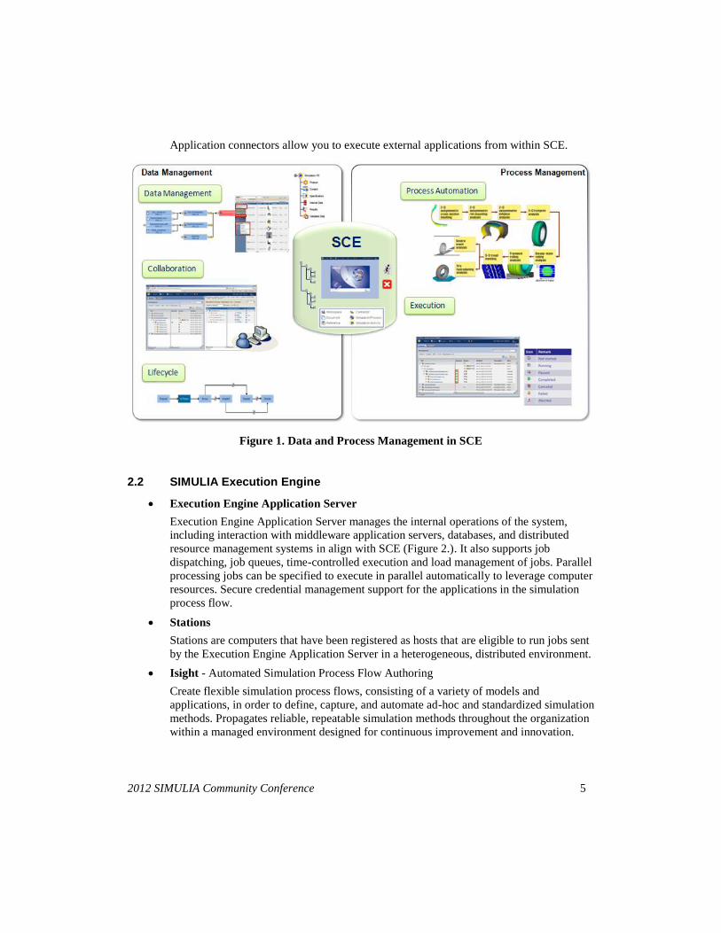
built by an OOTB solution. It needs actually many aspects of consideration on not only
implementations but also system roadmap and architecture. Moreover, for various business
environments and business processes, it is difficult to build a system using the only OOTB (Of
course, Dassault Systèmes SIMULIA is trying to increase the proportion of the OOTB and
minimize the proportion of customer-specific 'configuration' and 'customization' – Figure 3.).
Therefore, to construct the integrated simulation environment which our company pursues, the
following tasks were performed.
2012 SIMULIA Community Conference 7
Figure 3. SLM : Out of the Box; Configurable; Customizable
3.1 Tool Map and Roadmap
The objectives of VECS is to maximize the effect of the simulation by providing the multiple
disciplinary simulation environment that can predict the tire performance and suggest the design
direction without manufacturing and testing the real tire through the execution of simulation
covering structure analysis, vehicle dynamics and NVH. Therefore, the construction of VECS is
not only the system construction but also related to strategy and vision of Hankook Tire research
divisions. Most of existing simulation tools and workflows have been researched and developed
by each individual or department unit. However these tools have not been managed and shared
efficiently. So we have investigated and rearranged them to prepare an environment that integrates
simulation tools. All information for each simulation tool such as inputs, outputs and execution
procedures is illustrated as an intuitive graphic chart and aligned with the tire development process.
We call it “Tool Map” and keep it maintained for VECS. In addition, we have surveyed what
kinds of simulation tools will be researched and developed in near future and if VECS is feasible
to their needs and objectives.
Based on our “Tool Map” and SLM solution’s key features such as collaboration, simulation data
management, integration and process automation and decision support, the roadmap of VECS was
established and each step is as follows.
Phase1. Introduction/Reliability
- Simulation method establishment, expert usage, result report
Phase2. Bulk Simulation/Automation
- Simulation standardization/automation, design expectation, bulk execution
Phase3. Relation with Design & Test Data / Database
8 2012 SIMULIA Community Conference
- Simulation/test result analysis, tendency and accuracy verification
Phase4. Multi Performance / Integrated
- Simulation environment integration, performance prediction and analysis
Phase5. Decision Support / Simulation Leading Design
- Suggestion of design methodology applied statistical techniques
3.2 Pilot System Development
In order to construct a reliable VECS, we needed to validate technical feasibilities and user
acceptances via prototype and pilot systems. First of all, we have analyzed the SLM OOTB
features and derived the prototype system to check basic workflows.
Also we needed to compare the previous simulation automation system implemented by ourselves
with new prototype system to understand benefits of SLM key features. So, we chose the one of
simulation processes and applied it to OOTB of SLM.
By implementing a prototype system, we have been familiar with SLM solution environments and
could handle requirements and environment changes flexibly. As a result, we learned how to
manage virtual products, simulation groups and key results via SLM OOTB.
After the prototype system was derived, we implemented the pilot system based on it. We
analyzed the user interface and the detail logics for simulation automation s and made the “DFD”
(Data Flow Diagram) and “Functional Diagram”. The analyzed existing workflow was represented
under the “Team Central” of the SLM solution. We designed the data structure and workflow of
VECS based on the SLM lean data schema. Based on the flexible schema, new system UI and
storyboard were implemented. In addition, pre and post processing automations were implemented
and how to manage result data was planned.
3.3 Simulation Template
“Simulation Template” is one of the most important concepts in the SLM. It can be created by
standardization and formalization of the simulation execution process.
When we examine the process a simulation expert runs during FE simulations, the simulation
execution process looks similar but the detail of execution varies according to each expert. The
reason is that simulation experts rely on their own knowledge and experience. There are unclear
naming conventions and individual result reviews. So, it is difficult to compare and analyze
outcomes from multiple users. These factors increase the complexity of the simulation process
automation and the system design.
Additionally, the objective of VECS is to build the multi-disciplinary simulation environments
that predict the tire performance and set up the design direction. This doesn't mean to only collect
various “Simulation Templates”. Method developers can easily save the simulation process that he
can release it as a “Simulation Template”. But if the method developer creates the simulation
template as their own expression, it is difficult to compare and analyze various outcomes created
from multiple performance simulations.

2012 SIMULIA Community Conference 9
Therefore, we analyzed the previous simulation processes and standardized the way of expert’s
workflows. In order to facilitate the comparison and analysis, we adjusted the information level of
various results created by multiple performance simulation to the same line. The “Simulation
Template” created by these works allows a user who doesn't have engineering knowledge to carry
out the whole process by simple manipulation and acquire consistent outcomes.
In 2008, we migrated the simulation processes in the previous simulation automation system to the
“Simulation Template” of the SLM 2009. But it had some limitations. The problems of the
“Simulation Template” based on SLM 2009 were:
1) It doesn't support the parallel execution of “Simulation Activity”.
2) It can't add “Simulation Activity” depending on the conditions.
3) It doesn't support the conditional running of the process.
We gave these requirements to Dassault Systèmes SIMULIA and SIMULIA suggested the
combination of SLM V6R2010 and Isight. Although Isight is tool for optimization, it has many
functions for process automation and workflow integration. Isight automates a simulation process
by defining the parameters needed to run the simulation and combining with the specific function
components. Fortunately, Isight solved many pitfalls of the previous “Simulation Template”. In
addition, Isight increased the convenience of “Simulation Template” creation. In our previous
simulation automation system, the simulation expert had to receive help from the IT system expert
or learn the shell script programming of the LINUX system. However a simulation expert can
automate his simulation process with Isight by drag and drop or simple manipulations. As the
main agent of the simulation process automation moves from the system expert to the simulation
expert, the simulation expert can focus on the simulation technology development and enhance the
simulation knowledge.
3.4 Key Results Database
One of the main objectives of VECS construction is simulation data management. VECS creates
various results for each simulation. An ODB file, ABAQUS’s result file, is one of them. This file
depends on the size of the model but generally the file size is quite huge and occupies most of
storage space. Although the system has the large capacity storage, the integrated simulation
system produces many ODB files because the system is used by multiple users simultaneously.
So we need to delete these files periodically. Therefore, ODB file is converted into the small size
text or image file through the post-processing using the python based ABAQUS scripting. These
files are provided to users through intuitive user interface. SCE provides the Export/Import Rule
at the Simulation Activity to be able to move these files into the Simulation Document. In
addition, to prevent huge data from taking spaces after post-processing, all large data can be
deleted depending on execution options.
However, with only the file-based Simulation Document, it is difficult to retrieve sufficient
simulation results. Thus, we extracted key attributes from the contents of the results and stored
them as key results and restored in the database. So we are able to easily search and analyze the
data. And it is possible to connect with the design data and the test data.

10 2012 SIMULIA Community Conference
3.5 System Configuration
We are equipped with HPC (High Performance Computing) which has large storages in order to
get feedbacks of simulation results to a tire developer in a short period.
Looking at the system configuration, general users can access the system via web browsers. Web-
based systems have less spatial and temporal constraints, so a user doesn’t need to install an
additional program. SCE is a simulation central of ENOVIA (previous Matrix One), which can
manage simulation data and processes. A user sets the information of a simulation and runs the
simulation through the user interface of SCE or customized one, then SCE passes the job
execution to SEE server. SEE sends commands to the station(SEE client) that is specified in the
run option of the SCE. Simplifying complex simulation workflows is crucial to process
automation. Especially to encourage the usage of “Simulation Template”, it is necessary for non
experts and novices. So we used Isight to wrap a simulation workflow as a simple one. That is to
say that Isight workflows should be executed in batch mode in SEE. And for FE simulations such
as ABAQUS and LS-Dyna, LSF job scheduler commands are used within Isight component. LSF
head node distributes a job to each analysis node. Each analysis node shares files via the
SFS(HP’s network file system). When a simulation was finished, SCE saves output files or post-
processing result files at the specified simulation document by the import rule. (Figure 4.)
Figure 4. System Configuration
3.6 VECS Implementation
We have been continuously studying the requirements to build VECS and a lot of validations have
been performed on the pilot system. After several prototype and pilot systems were built by
ourselves, we carried out the co-work project with the Dassault Systèmes Korea experts and the
2012 SIMULIA Community Conference 11
development partners in order to enhance intuitive look and feel and system robustness. The
development scope of the co-work project is as follows.
Table 1. Scope of Development.
Fields Details Remarks
Simulation Data Management
Data version & permission management OOTB & Configuration
Data version management & Permission setting improvement
OOTB & Customizing
Simulation Business Collaboration
Simulation business collaboration Customizing
Simulation Data Tracing & Progress
Simulation data management Customizing
Simulation Business Process Improvement
Simulation business process improvement OOTB & Customizing
Simulation portal system improvement Customizing
Searching & Report improvement Customizing
Support Simulation Job Support simulation job Customizing
CAD data registration Customizing
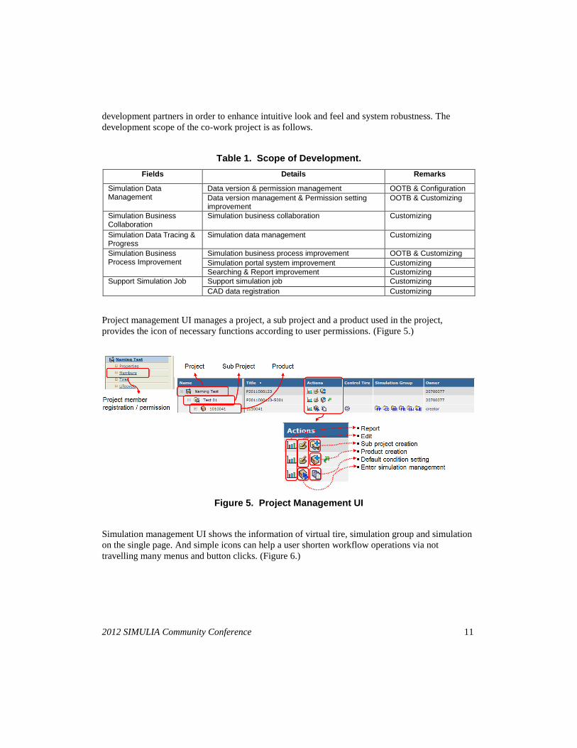
Project management UI manages a project, a sub project and a product used in the project,
provides the icon of necessary functions according to user permissions. (Figure 5.)
Figure 5. Project Management UI
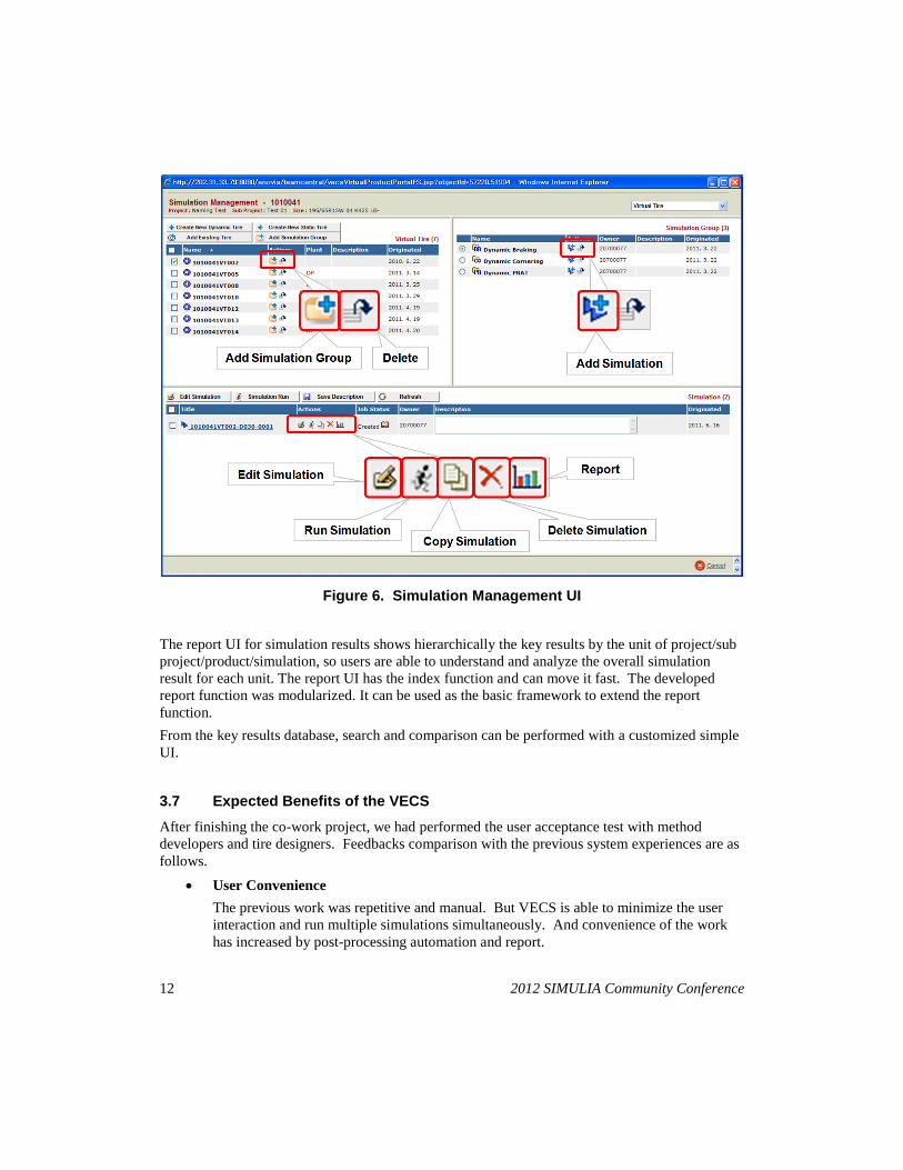
Simulation management UI shows the information of virtual tire, simulation group and simulation
on the single page. And simple icons can help a user shorten workflow operations via not
travelling many menus and button clicks. (Figure 6.)
12 2012 SIMULIA Community Conference
Figure 6. Simulation Management UI
The report UI for simulation results shows hierarchically the key results by the unit of project/sub
project/product/simulation, so users are able to understand and analyze the overall simulation
result for each unit. The report UI has the index function and can move it fast. The developed
report function was modularized. It can be used as the basic framework to extend the report
function.
From the key results database, search and comparison can be performed with a customized simple
UI.
3.7 Expected Benefits of the VECS
After finishing the co-work project, we had performed the user acceptance test with method
developers and tire designers. Feedbacks comparison with the previous system experiences are as
follows.
User Convenience
The previous work was repetitive and manual. But VECS is able to minimize the user
interaction and run multiple simulations simultaneously. And convenience of the work
has increased by post-processing automation and report.
2012 SIMULIA Community Conference 13
Management of the simulation model and data
The simulation result files are managed at the simulation document. The key results were
extracted from the result files and were built into the database. As the system manages
the simulation model and result by the database, users are able to trace and correlate the
input and the output. Also, it is possible to search and compare the simulation result.
Collaboration
VECS manages the simulation by group using the hierarchy of project/sub project and
can set the member permission for each project. By these functions, the tire developer
and the simulation expert can be working together and share the simulation results.
Simulation template development environment
The simulation expert can standardize and formalize the simulation process and the
development support through the simulation template using the SCE and Isight. The
simulation template makes it possible to share or manage the simulation knowledge and
know-how of the individual simulation expert at the system level.
4. Requirements for SLM OOTB Enhancement
In terms of strategic partnership with Dassault Systèmes SIMULIA, we have tested several SLM
versions via prototype and pilot systems since 2008. Hankook Tire has provided functional
requirements from the perspective of tire industry and has got valuable supports from SIMULIA.
We believe that now the SLM solution has provided most of necessary functionalities we expected.
To keep VECS more reliable and be expanded to other regions, we have considered requirements
as follows.
4.1 Solution Integration
Synchronization
Currently, the SLM solution is connected by several products (SCE, SEE, Isight and so
on). So, one product cannot completely control the function of the others. For example,
if a command is executed through the path of SCE --> Isight --> LSF and occurs errors,
the log of job execution is too complex to recognize the exact status of the task. Thus,
consolidated or simplified synchronization between products is required through the
solution integration.
Limitation of loosely coupled Isight integration
Isight Runtime Gateway is used for checking the progress of the simulation process,
partial re-run, post-processing and so on. These functions are very useful to novice users.
However the functions of Isight runtime Gateway are not implemented in the SCE web
UI. Those of functions would be good for process monitoring and intuitive post-
processing.
Simplification of licensing policy

14 2012 SIMULIA Community Conference
The SLM solution consists of various products (SCE, SEE, Isight and so on) and is
managed by different licenses for each product. The license structure is very complex.
So, simplification of license management is also required.
4.2 Utilities for System Administrator
License Management
While a system in production, the license usage is less than the count of available licenses
in general. But more licenses are required when development s are proceeded in parallel.
In this case, the license should be redistributed according to the importance of the project.
In other ways, a system administrator stops an existing simulation and has to run
simulations with priorities. If a system has an administrator mode that can manage the
simulation license or it tells how many licenses are available, it would be helpful for the
system operation.
Job Maintenance
The function to let a system administrator can monitor and control the entire simulation
jobs on the system is needed. As mentioned above, we need to manage a simulation job
because of the lack of licenses. Also, the system administrator may need to terminate a
job when the job has a loop or to give the quota for each user. The present SCE/SEE
don’t have these functions, there is room for improvement.
5. Future Work
VECS projects are currently underway. And VECS will support Decision Support through
collaboration with Dassault Systèmes SIMULIA and association of the test data and PLM product
information/process.
6. References
1. SIMULIA : The Case for Simulation Life Cycle Management; report 1 of 3; White Paper
2. SIMULIA : The Case for Simulation Life Cycle Management; report 2 of 3; White Paper
3. SIMULIA : The Case for Simulation Life Cycle Management; report 3 of 3; White Paper
4. CIMdata : Simulation Lifecycle Management “More than data management for simulation”
5. SIMULIA : SIMULIA Scenario Definition User’s Guide