Embed Size (px)
Citation preview
INTEGRATED SECURITY SYSTEM PERFORMANCE SPECIFICATION FOR DMP MODEL XT SERIES™ CONTROL PANELS
1.0 GENERAL1.1 Manufacturer
A. The manufacturer shall have at least thirty (30) years of experience in the role of fire and security control manufacturing, and a proven track record of forward and backward compatibility for a minimum of twenty (20) years for its product’s auxiliary devices, including system keypads, annunciation devices, zone expansion modules, and addressable detection devices.B. The manufacturer must also manufacture receiving equipment that is compatible with standard dial-up telephone lines and network monitoring equipment that is compatible with a LAN, WAN, Internet, and CDMA or HSPA+ Cellular Communications. The receiving equipment shall be capable of receiving all status and alarm messages generated by the system. The receiving equipment shall be capable of updating the panel operating program and the system date and time.C. Intrusion detection/Door Control Panel/Household Fire Warning System equipment manufacturer shall be: Digital Monitoring Products, Inc. (DMP)2500 N. Partnership Boulevard, Springfield, MO 65803 Telephone (417) 831-9362FAX (417) 831-1325
1.2 InstallerA. The installing company shall show proof of having regular experience with design, installation, service, and maintenance of manufactured systems for a minimum of the last twelve (12) calendar months from the project start date. Each system installer and service person must provide manufacturer certification of technical training for installation, service, and system maintenance. Certification shall be proven with an official document issued by the manufacturer.B. The installing company shall provide a minimum of 8 (eight) verifiable references from its clients where the manufacturer’s system has been installed within the last twelve (12) calendar months from the project start date.C. The installing company shall furnish and install a complete electrically supervised XT Series Panel, as detailed in this specification. The system shall be inclusive of all necessary function, monitoring, and control capability as detailed herein and on accompanying shop drawings.E. The installing company shall become familiar with all details of the work, verify all dimensions in the field, and shall advise the Architect of any discrepancy before performing the work. Materials shall be installed in strict compliance with local building codes. All work shall be performed in accordance with Digital Monitoring Products, Inc. instructions. Associated components must be installed and serviced by a dealer in good standing that is factory-trained by Digital Monitoring Products.
1.3 Central Reporting StationA. The central reporting station contractor must possess a certification as a "Mercantile Police Station" or "Mercantile Burglar Alarm Systems" company. A copy of the certification shall be attached as a part of this bid package.B. The actual alarm signal receipt and processing is a significant portion of the scope of work. Third party and/ or contract stations are permitted. The monitoring station must be certificated for Protective Signaling Services or Central Reporting Station Signaling Services. A copy of the station certificate shall be attached as part of this bid package.C. The monitoring station must provide openings/ closing activity reports, activity day and time, authorized individual, office name and account number and the system type being monitored. These reports are to be mailed to the user’s office at the end of each month. The Office Manager or Contract Administrator may request an additional report if an incident occurs.
XT Series Intrusion/Access/Fire Detection Specification
2
D. The contractor must have a valid Alarm Operator License. A copy of licenses shall be attached as part of this bid package.E. The contractor may be required to monitor a portion of the alarm systems by way of the end user data network.F. The Contractor shall become familiar with all work details, verify all dimensions in the field, and shall advise the Architect of any discrepancy before performing the work.G.The end user shall not incur any central station setup charges by the contractor to receive alarm signals by way of the end user data network.
2.0 SCOPE2.1 Requirements
A. Furnish and install a complete Intrusion Detection/Access Control system or Household Fire Warning System with the performance criteria detailed in this specification. The system shall be inclusive of all necessary functions, monitoring, and control capability as detailed herein and on accompanying Shop drawings.B. This specification document provides the requirements for the installation, programming, and configuration of a complete Command Processor Panel. This system shall include, but not be limited to:• Control panel • Integrated Network Communication • Integrated Wireless Receiver• Cellular Add-on Communication Modules (LTE) • System cabinet• Power supply • Digital Signaling Line Circuits (SLC) • Annunciator/keypad bus• Batteries • Wiring • Conduit• Associated peripheral devices• Other relevant components and accessories required to furnish and install a complete and operational addressable reporting Life Safety System.
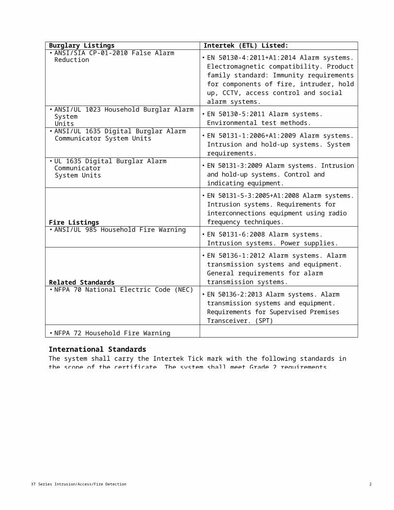
2.2 StandardsThe system shall be listed as a Power Limited Device and be listed under the standards in the table. Each system shall be supplied with complete details on all installation criteria necessary to meet all of the listings.
Burglary Listings Intertek (ETL) Listed:• ANSI/SIA CP-01-2010 False Alarm Reduction • EN 50130-4:2011+A1:2014 Alarm systems.
Electromagnetic compatibility. Product family standard: Immunity requirements for components of fire, intruder, hold up, CCTV, access control and social alarm systems.
• ANSI/UL 1023 Household Burglar Alarm SystemUnits
• EN 50130-5:2011 Alarm systems. Environmental test methods.
• ANSI/UL 1635 Digital Burglar AlarmCommunicator System Units • EN 50131-1:2006+A1:2009 Alarm systems.
Intrusion and hold-up systems. System requirements.
• UL 1635 Digital Burglar Alarm CommunicatorSystem Units
• EN 50131-3:2009 Alarm systems. Intrusion and hold-up systems. Control and indicating equipment.
Fire Listings
• EN 50131-5-3:2005+A1:2008 Alarm systems. Intrusion systems. Requirements for interconnections equipment using radio frequency techniques.
• ANSI/UL 985 Household Fire Warning • EN 50131-6:2008 Alarm systems. Intrusion systems. Power supplies.
XT Series Intrusion/Access/Fire Detection Specification
2
Related Standards
• EN 50136-1:2012 Alarm systems. Alarm transmission systems and equipment. General requirements for alarm transmission systems.
• NFPA 70 National Electric Code (NEC) • EN 50136-2:2013 Alarm systems. Alarm transmission systems and equipment. Requirements for Supervised Premises Transceiver. (SPT)
• NFPA 72 Household Fire Warning
International StandardsThe system shall carry the Intertek Tick mark with the following standards in the scope of the certificate. The system shall meet Grade 2 requirements.

3XT Series Intrusion/Access/Fire Detection Specification
3.0 SUBMITTALS3.1 General Requirements
The contractor shall submit three (3) complete sets of documentation within thirty (30) calendar days after contract award date. Indicated in the document shall be the manufacturers’ names, catalog number, type, size, style, rating, and catalog data sheets for all items proposed to meet these specifications.
3.2 Shop DrawingsShop drawings shall be submitted in accordance with Section 3.0 Submittals and shall consist of a complete list of equipment and materials, including manufacturer’s descriptive and technical literature, performance charts and curves, catalog cuts, and installation instructions.
3.3 As-Built DrawingsThe contractor shall provide a complete set of as-built drawings for the entire system upon installation completion. These drawings shall include, but not be limited to, the exact locations of all equipment, connections between all equipment, and wiring for all equipment as the system is installed.
3.4 Spare Parts DataAfter shop drawings are approved, and not later than thirty (30) calendar days prior to the date of beneficial occupancy, a list of spare parts data for each item of specified materials and equipment shall be submitted. The data shall include a complete list of parts and supplies with current unit prices and source of supply.Spare parts shall consist of, but not be limited to, five (5) percent of all initiating and notification appliances with a minimum of one (1) each. All spare parts shall be on site prior to commencement of acceptance testing. Depleted spare parts shall be replaced prior to beneficial occupancy.
3.5 Operating DocumentsThe contractor shall furnish to the architect operating instructions outlining the step-by-step procedures required for system start-up, operation, and shutdown at least thirty (30) calendar days prior to acceptance test. The instructions shall include the manufacturer’s name, system model number, service manual, parts list, and a description of all equipment and their basic operating features.
3.6 Maintenance DocumentsThe contractor shall furnish maintenance instructions listing routine maintenance procedures, possible breakdowns and repairs, and troubleshooting guides at least 30 calendar days prior to acceptance test.
3.7 Performance Test ReportsUpon the installed system completion and testing, test reports shall be submitted in booklet form showing all field tests performed to prove compliance with specified performance criteria.
3.8 WarrantyA copy of the manufacturer’s warranty for all equipment and materials shall be provided. Warranty shall be for all equipment, materials, installation, and workmanship for a minimum of three (3) years, unless otherwise specified.
XT Series Intrusion/Access/Fire Detection Specification4
4.0 GENERAL COMPONENT REQUIREMENTS4.1. Component Enclosure
Housings, power supply enclosures, terminal cabinets, control units, and other component housings, collectively referred to as enclosures shall be so formed and assembled as to be sturdy and rigid. If sheet steel is used in the fabrication of enclosures, it shall be not less than an 18-gauge door with a 20-gauge box frame. Where exposed pins, the hinges shall be of the tight pin type or the ends of hinge pins shall be tack welded to prevent ready removal. Doors having a latch edge length of less than 24 inches shall be provided with a single lock.
4.2 Electronic ComponentsA. All system electronic components shall be solid-state type, mounted on printed circuit boards. Light duty relays and similar switching devices shall be solid-state type or electromechanical.B. The panel shall have an over current notification LED that lights when devices connected to the Keypad Bus draw more current than the panel is rated for. When the over current LED lights, the Keypad bus shuts down.
4.3 Control UnitA. A battery test shall be automatically performed to test the integrity of the standby battery. The test shall disconnect the standby battery from the charging circuit and place a load on the battery. This test shall be performed no more than every hour.B. The control unit shall be capable of operating and supervising notification appliance devices as well as addressable initiating detection devices, integrated wireless receiver, integrated cellular communicator, and integrated network communications.C. Control unit must be “Flash ROM” updatable, and program must be held in non-volatile RAM.D. Control Panel shall have the ability for integrated built-in Network Communications, CDMA or HSPA+ Cellular Communication Add-on Modules, and two-way 900 MHz Spread Spectrum wireless communications to two-way wireless initiating devices.
4.4 Remote AnnunciatorsA. The system shall support a maximum of eight (8) supervised remote annunciators with the identical capabilities, functions and display layout. Operation of the remote annunciators shall be limited to authorized users by the use of a code or key.B. The remote annunciators shall be capable of operating at a maximum wiring distance of 15,000 feet from the control unit on unshielded, non-twisted cable.
4.5 Control DesignationsControls shall be provided to ensure ease of operation of all specified characteristics. Where applicable, clockwise rotation of controls shall result in an increasing function. controls, switches, visual signals and indicating devices, input and output connectors, terminals and test points shall be clearly marked or labeled on the hardware to permit quick identification of intended use and location.
4.6 Test ModesA. The system shall include a provision that permits testing from any alphanumeric keypad. The test shall include standby battery, alarm bell or siren, and communication to the central station.B. The system shall include a provision for an automatic, daily, weekly, thirty (30) day, or up to sixty (60) day communication link test from the control panel installation site to the central station. The communication test shall be capable of separately testing over dial up, network, and or cellular communication paths.C. The system shall include a provision for displaying the internal system power and wiring conditions. Internal monitors shall include the bell circuit, AC power, battery power, panel box tamper, phone trouble, and network trouble.
5 XT Series Intrusion/Access/Fire Detection Specification
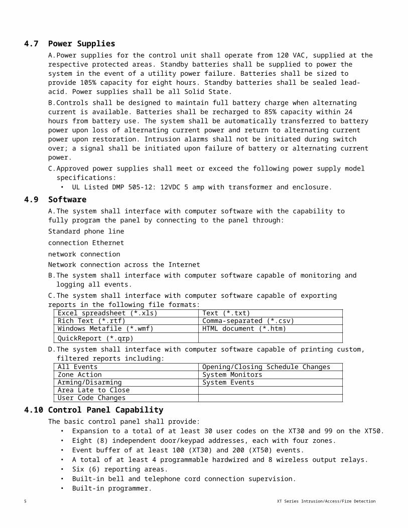
4.7 Power SuppliesA. Power supplies for the control unit shall operate from 120 VAC, supplied at the respective protected areas. Standby batteries shall be supplied to power the system in the event of a utility power failure. Batteries shall be sized to provide 105% capacity for eight hours. Standby batteries shall be sealed lead-acid. Power supplies shall be all Solid State.B. Controls shall be designed to maintain full battery charge when alternating current is available. Batteries shall be recharged to 85% capacity within 24 hours from battery use. The system shall be automatically transferred to battery power upon loss of alternating current power and return to alternating current power upon restoration. Intrusion alarms shall not be initiated during switch over; a signal shall be initiated upon failure of battery or alternating current power.C. Approved power supplies shall meet or exceed the following power supply model specifications:
• UL Listed DMP 505-12: 12VDC 5 amp with transformer and enclosure.4.9 Software
A. The system shall interface with computer software with the capability to fully program the panel by connecting to the panel through:Standard phone line connection Ethernet network connectionNetwork connection across the InternetB. The system shall interface with computer software capable of monitoring and logging all events.C. The system shall interface with computer software capable of exporting reports in the following file formats:
Excel spreadsheet (*.xls) Text (*.txt)Rich Text (*.rtf) Comma-separated (*.csv)Windows Metafile (*.wmf) HTML document (*.htm)QuickReport (*.qrp)
D. The system shall interface with computer software capable of printing custom, filtered reports including:All Events Opening/Closing Schedule ChangesZone Action System MonitorsArming/Disarming System EventsArea Late to CloseUser Code Changes
4.10 Control Panel CapabilityThe basic control panel shall provide:
• Expansion to a total of at least 30 user codes on the XT30 and 99 on the XT50.• Eight (8) independent door/keypad addresses, each with four zones.• Event buffer of at least 100 (XT30) and 200 (XT50) events.• A total of at least 4 programmable hardwired and 8 wireless output relays.• Six (6) reporting areas.• Built-in bell and telephone cord connection supervision.• Built-in programmer.• Virtual Keypad™ App for iPhone, iPad, or Android Device for control of the security system.• Z-Wave control through 738Z module to control Z-Wave compatible devices.
XT Series Intrusion/Access/Fire Detection Specification
6
5.0 FUNCTIONAL DESCRIPTIONS5.1 System Description
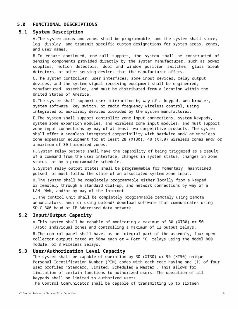
A. The system areas and zones shall be programmable, and the system shall store, log, display, and transmit specific custom designations for system areas, zones, and user names.B. To ensure continued, one-call support, the system shall be constructed of sensing components provided directly by the system manufacturer, such as power supplies, motion detectors, door and window position switches, glass break detectors, or other sensing devices that the manufacturer offers.C. The system controller, user interfaces, zone input devices, relay output devices, and the system signal receiving equipment shall be engineered, manufactured, assembled, and must be distributed from a location within the United States of America.D. The system shall support user interaction by way of a keypad, web browser, system software, key switch, or radio frequency wireless control, using integrated or auxiliary devices provided by the system manufacturer.E. The system shall support controller zone input connections, system keypads, system zone expansion modules, and wireless zone input modules, and must support zone input connections by way of at least two competitive products. The system shall offer a seamless integrated compatibility with hardwire and/ or wireless zone expansion equipment for at least 28 (XT30), 48 (XT50) wireless zones and/ or a maximum of 30 hardwired zones.F. System relay outputs shall have the capability of being triggered as a result of a command from the user interface, changes in system status, changes in zone status, or by a programmable schedule.G. System relay output states shall be programmable for momentary, maintained, pulsed, or must follow the state of an associated system zone input.H. The system shall be completely programmable either locally from a keypad or remotely through a standard dial-up, and network connections by way of a LAN, WAN, and/or by way of the Internet.I. The control unit shall be completely programmable remotely using remote annunciators, and/ or using upload/ download software that communicates using SDLC 300 baud or IP Addressed data network.
5.2 Input/Output CapacityA. This system shall be capable of monitoring a maximum of 30 (XT30) or 50 (XT50) individual zones and controlling a maximum of 12 output relays.B. The control panel shall have, as an integral part of the assembly, four open collector outputs rated at 50mA each or 4 Form “C” relays using the Model 860 module, or 8 wireless relays.
5.3 User/Authorization Level CapacityThe system shall be capable of operation by 30 (XT30) or 99 (XT50) unique Personal Identification Number (PIN) codes with each code having one (1) of four user profiles “Standard, Limited, Scheduled & Master”. This allows for limitation of certain functions to authorized users. The operation of all keypads shall be limited to authorized users.The Control Communicator shall be capable of transmitting up to sixteen characters for the user’s name to the central station receiver.
5.4 KeypadsA. The system shall support a maximum of eight (8) keypads with alphanumeric display. Each keypad shall be capable of arming and disarming any system area based on a pass code or Proximity key authorization. The keypad alphanumeric display shall provide complete prompt messages during all stages of operation and system programming and display all relevant operating and test data.B. Communication between the control panel and all keypads and zone expanders shall be multiplexed over a non-shielded multi-conductor cable, as recommended by the manufacturer. This cable shall also provide the power to all keypads, zone expanders, output expanders, and other power consuming detection devices.

XT Series Intrusion/Access/Fire Detection Specification
6
C. If at any time a keypad does not detect polling, the alphanumeric display shall indicate "SYSTEM TROUBLE". If at any time a keypad detects polling but not for its particular address, the alphanumeric display shall indicate "NON POLLED ADDR". The system shall display all system troubles at selected keypads with distinct alphanumeric messages.D. The keypad shall include self-test diagnostics enabling the installer to test all keypad functions: display test, key test, zone test, LED test, relay test, tone test, and address test.
7 XT Series Intrusion/Access/Fire Detection Specification
E. The keypad shall provide an easy-to-read English text display. The text shall exactly match the text seen in all software reports, keypad displays, and central station reports.F. The keypad user interface shall be a simple-to-use, menu-driven help system that is completely user friendly.G. The control panel shall support a keypad interface accessible on the World Wide Web in a browser window. The web-accessible keypad interface shall provide at least five (5) programmable hyperlinks for camera access or other use.
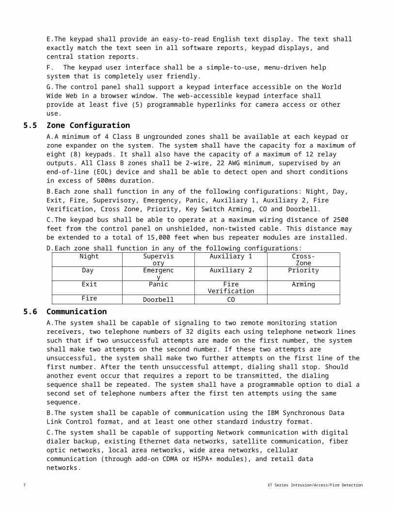
5.5 Zone ConfigurationA. A minimum of 4 Class B ungrounded zones shall be available at each keypad or zone expander on the system. The system shall have the capacity for a maximum of eight (8) keypads. It shall also have the capacity of a maximum of 12 relay outputs. All Class B zones shall be 2-wire, 22 AWG minimum, supervised by an end-of-line (EOL) device and shall be able to detect open and short conditions in excess of 500ms duration.B. Each zone shall function in any of the following configurations: Night, Day, Exit, Fire, Supervisory, Emergency, Panic, Auxiliary 1, Auxiliary 2, Fire Verification, Cross Zone, Priority, Key Switch Arming, CO and Doorbell.C. The keypad bus shall be able to operate at a maximum wiring distance of 2500 feet from the control panel on unshielded, non-twisted cable. This distance may be extended to a total of 15,000 feet when bus repeater modules are installed.D. Each zone shall function in any of the following configurations:
Night Supervisory
Auxiliary 1 Cross-Zone
Day Emergency
Auxiliary 2 Priority
Exit Panic Fire Verification
Arming
Fire Doorbell CO5.6 Communication
A. The system shall be capable of signaling to two remote monitoring station receivers, two telephone numbers of 32 digits each using telephone network lines such that if two unsuccessful attempts are made on the first number, the system shall make two attempts on the second number. If these two attempts are unsuccessful, the system shall make two further attempts on the first line of the first number. After the tenth unsuccessful attempt, dialing shall stop. Should another event occur that requires a report to be transmitted, the dialing sequence shall be repeated. The system shall have a programmable option to dial a second set of telephone numbers after the first ten attempts using the same sequence.B. The system shall be capable of communication using the IBM Synchronous Data Link Control format, and at least one other standard industry format.C. The system shall be capable of supporting Network communication with digital dialer backup, existing Ethernet data networks, satellite communication, fiber optic networks, local area networks, wide area networks, cellular communication (through add-on CDMA or HSPA+ modules), and retail data networks.
5.7 Integrated Network CommunicationA. The control panel shall be capable of asynchronous network communication with a check-in time between 15 and 240 minutes. If communication is unsuccessful the control panel shall be capable of attempting backup communication through any of the available communication methods to the same receiver or a backup receiver.B. Network communication between the control panel and the receiver shall be in a proprietary communication format.C. The control panel shall be capable of supporting Dynamic Host Communication Protocol (DHCP) Internet Protocol (IP) addressing.D. The control panel shall be capable of two-way network communication using standard Ethernet 10/100 in a LAN, WAN, or Internet configuration.
XT Series Intrusion/Access/Fire Detection Specification
8
5.8 Cellular CommunicationA. The control panel shall have the capability of integrated or plug-in add-on LTE Cellular communications.B. The control panel shall have the capability of back up or primary cellular communications via integrated or plug in add on cellular module fully powered by the control panel without the need for an external power supply or enclosure.
5.9 Integrated SMS CommunicationA. The control panel shall have the ability to communicate messages to SMS accounts with the following information:
A. Zone Alarms by Zone Name• Zone Troubles by Zone Name• Zone Bypass by User• Disarming (Opening) by User• Arming (Closings) by User• Late to Close• AC Power Trouble and Restoral• System Low Battery and Restoral• Ambush• Abort, Cancel, and Alarm Verified by User• Check-in by User• User Inactivity
9 XT Series Intrusion/Access/Fire Detection Specification
6.0 FALSE ALARM REDUCTION FEATURESThe system shall be capable of providing false alarm reduction features, functions, capabilities, or processes that either require alarms be verified or potential alarms be corrected before a system or zone can be placed into an armed state. The system must meet ANSI/UL CP-01-2007 False Alarm Reduction requirements.
6.1 Exit Error Alert and ReportingThe panel shall be able to provide an automatic function to prevent a false alarm from occurring if an exit door does not properly close after the system is armed.
6.2 Entry and Exit Delay AnnunciationA. When arming, the system shall provide clear annunciation indicators to the user about the need to exit the premises prior to the exit delay time expiring.B. When disarming, the system shall notify the user the need to disarm the system prior to the entry delay time expiring.
6.3 Remote AnnunciationThe system shall be able to provide entry and exit delay time period notification. This notification can be from DMP keypads, remote annunciators, or bell tests.
6.4 Cancel ReportingThe system shall be capable of sending a Cancel report to the central station if the system is disarmed while the alarm is still sounding. The Cancel report shall be sent after the alarm report to notify the central station that an authorized user has cancelled the alarm that was received.
6.5 System TestingThe system shall offer testing features that are simple, quick, and complete and provide the highest measure of safety by ensuring that alarm conditions are detected and communicated to the proper authorities in a timely manner and on a regularly scheduled basis.
6.6 Ambush CodeThe system shall offer an ambush code for those dangerous encounters where the user is instructed to either arm or disarm the system under threat of harm. The ambush code shall disarm the system without giving local indication of an alarm that might put the user’s well-being in jeopardy.
6.7 Two-Button Panic FeatureThe system shall support DMP keypads that provide the option to use only two-button panic codes. The user shall be required to press and hold two designated keys for approximately two seconds before the system generates a panic alarm.
6.8 Fire Verify Zones (Residential)The system shall support Fire Verify zones to help the panel verify the existence of an actual fire condition before it sends an alarm report to the central station. The Fire Verify zone shall require the panel to perform a Sensor Reset whenever a device connected to a Fire Verify zone initiates an alarm. This shall begin a verification period during which the panel waits for a second alarm initiation. If the original zone or any other Fire Verify zone on the panel initiates an alarm within the next 120 seconds, the panel shall recognize this as an actual alarm and send an alarm report to the central station.
6.9 Cross-Zoning ProtectionThe system shall support cross-zoning as a means of requiring two device trips to occur within a short period of time before sounding an alarm and sending an alarm report to the central station. Supported device trips shall be from one device that trips two times, or from two devices that each trip once.
6.10 Swinger Zone BypassingThe system shall be capable of automatically bypassing a zone if it goes into an alarm or trouble condition two times within a one-hour period. The panel shall be able to track the number of times the zone trips while armed and compare that against a programmed number. When that number is reached, the panel shall be able to automatically bypass the zone. The panel shall be capable of resetting the zone when the area to which it is assigned disarms, is manually reset from the keypad or remotely, or remains normal for one hour.
XT Series Intrusion/Access/Fire Detection Specification
10
6.11 Recently Armed ReportThe system shall be capable sending a System Recently Armed report, along with a zone alarm report, to the central station any time an alarm occurs within five minutes of the system arming. The System Recently Armed report allows the central station operator to follow a "call the subscriber first" procedure instead of immediately dispatching the police to what could be a false alarm.
6.12 Transmit DelayThe system shall be capable of programming the panel to wait up to 60 seconds before sending burglary alarm reports to the central station. If an alarm is accidental, the user shall be able to disarm the system within the programmed Transmit Delay time. An Abort report shall be sent in place of an alarm report after the system disarms. During the alarm, sirens and panel relay outputs shall not be delayed and shall still provide local condition annunciation.
6.13 Call Waiting CancelThe system shall be capable of being programmed to cancel call waiting any time the panel dials the receiver number to send a report.
6.14 Cancel/VerifyThe system shall be capable of sending either a Cancel Report or Verify Report to the Central Station to signify that the end user has Canceled an alarm or Verified an alarm condition.
6.15 Attrition Detection™ Prompts You to Call Your CustomerThe DMP Attrition Detection feature shall give advance warning that a customer may be preparing to cancel their monitoring contract. When activated, this feature will give notification if there is no system activity for the number of days selected in programming.
6.16 Zone InactivityZone Inactivity, easily monitor’s a person living alone. If there is no activity at the premises within the programmed number of hours, the system shall transmit an email/SMS message to your computer, PDA, and/or cell phone. The Central Station shall also receive an alert.
6.17 Zone AuditThe Zone Audit feature shall allow programming the panel to send an alert when the sensor fails to trip within the specified number of days. This feature helps identify potential sensor problems, including sensors deactivated to bypass faults.
6.18 Late to Open/Early to CloseThis feature shall send a message to the central station if the facility isn’t opened on time or closed before the scheduled time.
11
XT Series Intrusion/Access/Fire Detection Specification
7.0 FIRE CONTROL SPECIFICATIONS7.1 Standards for Household Fire Warning System
The Alarm Control Panel shall be listed as a Power Limited Device and be listed under the standards below. Each system shall be supplied with complete details on all installation criteria necessary to meet all of the listings.Fire Listings Related Listing• ANSI/UL 985 Household Fire Warning • California State Fire Marshal
7.2 KeypadsThe system shall include a menu selected "SENSOR RESET" option. This option, without disarming and re- arming the fire system, with use of any pass code, shall reset smoke detectors after they have been tripped.
7.3 Zone ConfigurationA. The alarm system shall have a minimum of one (1) Class B ungrounded 2-wire smoke detector zone available from the control panel.B. The system shall be capable of providing a maximum of 17 independent, 2-wire, and 12 VDC powered zones to power smoke detectors.
7.4 AnnunciatorsA. The alarm system shall support remote annunciators that offer silencing of alarms, reset sensors, and testing of the system.B. If at any time a remote annunciator does not detect polling the remote annunciator shall indicate “SYSTEM TROUBLE” on its alphanumeric LCD display within 200 seconds. If at any time the remote annunciator detects polling, but not for its particular address, the alphanumeric display shall indicate “NON- POLLED ADDR”.
7.5 Annunciation Lamps/LEDsA. Visual Annunciators used on Annunciator modules and elsewhere throughout the system shall be either electric lamps or light emitting diodes (LEDs or LCDs). Annunciators shall be so connected in the circuit that Annunciator failure, socket or protective circuitry shall not result in an improper or indeterminate signal. Lamps of varying types, voltage, and wattage shall have bases and sockets that prevent incorrect replacement.B. The control unit shall be completely programmable remotely using remote annunciators, and/ or using upload/ download software that communicates using SDLC 300 baud, or IP Addressed data network.
XT Series Intrusion/Access/Fire Detection Specification
12
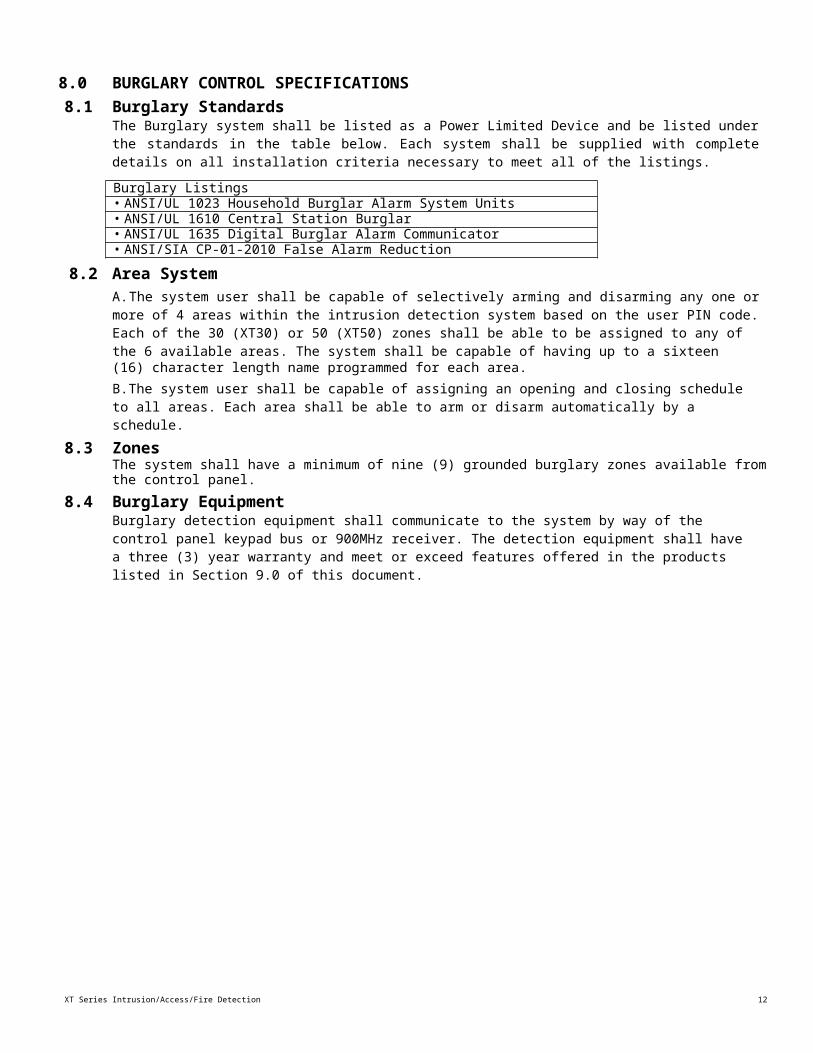
8.0 BURGLARY CONTROL SPECIFICATIONS8.1 Burglary Standards
The Burglary system shall be listed as a Power Limited Device and be listed under the standards in the table below. Each system shall be supplied with complete details on all installation criteria necessary to meet all of the listings.Burglary Listings• ANSI/UL 1023 Household Burglar Alarm System Units• ANSI/UL 1610 Central Station Burglar• ANSI/UL 1635 Digital Burglar Alarm Communicator• ANSI/SIA CP-01-2010 False Alarm Reduction
8.2 Area SystemA. The system user shall be capable of selectively arming and disarming any one or more of 4 areas within the intrusion detection system based on the user PIN code. Each of the 30 (XT30) or 50 (XT50) zones shall be able to be assigned to any of the 6 available areas. The system shall be capable of having up to a sixteen(16) character length name programmed for each area.B. The system user shall be capable of assigning an opening and closing schedule to all areas. Each area shall be able to arm or disarm automatically by a schedule.
8.3 ZonesThe system shall have a minimum of nine (9) grounded burglary zones available from the control panel.
8.4 Burglary EquipmentBurglary detection equipment shall communicate to the system by way of the control panel keypad bus or 900MHz receiver. The detection equipment shall have a three (3) year warranty and meet or exceed features offered in the products listed in Section 9.0 of this document.
13
XT Series Intrusion/Access/Fire Detection Specification
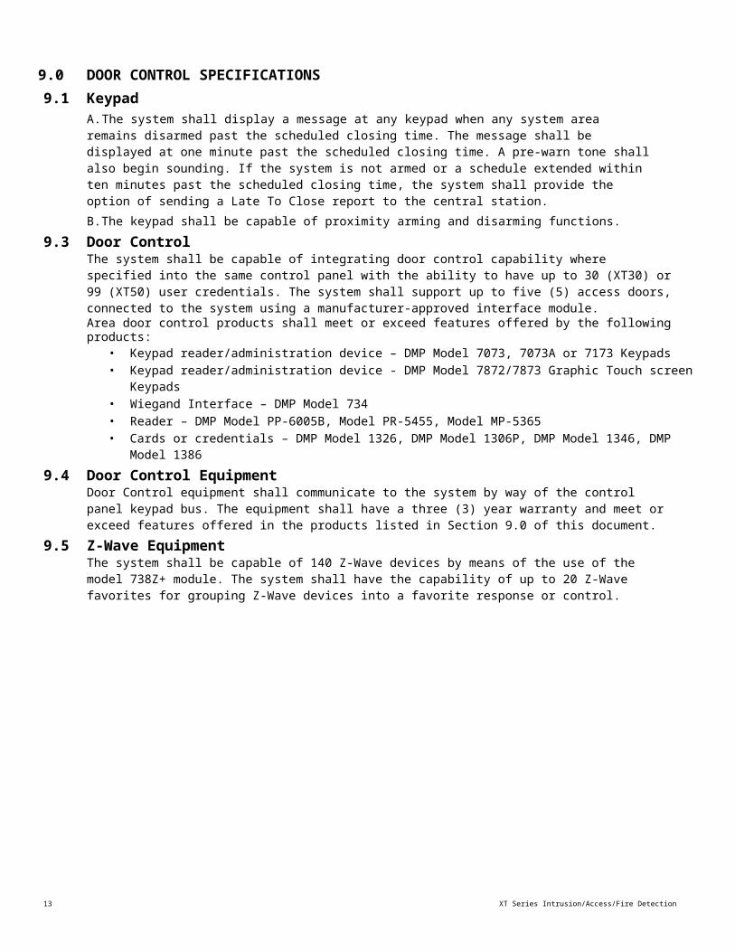
9.0 DOOR CONTROL SPECIFICATIONS9.1 Keypad
A. The system shall display a message at any keypad when any system area remains disarmed past the scheduled closing time. The message shall be displayed at one minute past the scheduled closing time. A pre-warn tone shall also begin sounding. If the system is not armed or a schedule extended within ten minutes past the scheduled closing time, the system shall provide the option of sending a Late To Close report to the central station.B. The keypad shall be capable of proximity arming and disarming functions.
9.3 Door ControlThe system shall be capable of integrating door control capability where specified into the same control panel with the ability to have up to 30 (XT30) or 99 (XT50) user credentials. The system shall support up to five (5) access doors, connected to the system using a manufacturer-approved interface module.Area door control products shall meet or exceed features offered by the following products:
• Keypad reader/administration device – DMP Model 7073, 7073A or 7173 Keypads• Keypad reader/administration device - DMP Model 7872/7873 Graphic Touch screen Keypads• Wiegand Interface – DMP Model 734• Reader – DMP Model PP-6005B, Model PR-5455, Model MP-5365• Cards or credentials – DMP Model 1326, DMP Model 1306P, DMP Model 1346, DMP Model
13869.4 Door Control Equipment
Door Control equipment shall communicate to the system by way of the control panel keypad bus. The equipment shall have a three (3) year warranty and meet or exceed features offered in the products listed in Section 9.0 of this document.
9.5 Z-Wave EquipmentThe system shall be capable of 140 Z-Wave devices by means of the use of the model 738Z+ module. The system shall have the capability of up to 20 Z-Wave favorites for grouping Z-Wave devices into a favorite response or control.

XT Series Intrusion/Access/Fire Detection Specification
14
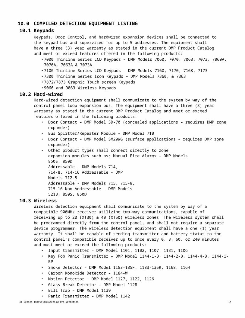
10.0 COMPILED DETECTION EQUIPMENT LISTING10.1 Keypads
Keypads, Door Control, and hardwired expansion devices shall be connected to the keypad bus and supervised for up to 5 addresses. The equipment shall have a three (3) year warranty as stated in the current DMP Product Catalog and meet or exceed features offered in the following products:
• 7000 Thinline Series LCD Keypads – DMP Models 7060, 7070, 7063, 7073, 7060A, 7070A, 7063A & 7073A• 7100 Thinline Series LCD Keypads – DMP Models 7160, 7170, 7163, 7173• 7300 Thinline Series Icon Keypads – DMP Models 7360, & 7363• 7872/7873 Graphic Touch screen Keypads• 9060 and 9063 Wireless Keypads
10.2 Hard-wiredHard-wired detection equipment shall communicate to the system by way of the control panel loop expansion bus. The equipment shall have a three (3) year warranty as stated in the current DMP Product Catalog and meet or exceed features offered in the following products:
• Door Contact – DMP Model SD-70 (concealed applications – requires DMP zone expander)• Bus Splitter/Repeater Module – DMP Model 710• Door Contact – DMP Model SM20WG (surface applications – requires DMP zone expander)• Other product types shall connect directly to zone expansion modules
such as: Manual Fire Alarms – DMP Models 850S, 850DAddressable - DMP Models 714, 714-8, 714-16 Addressable - DMP Models 712-8Addressable - DMP Models 715, 715-8, 715-16 Non-Addressable - DMP Models 521B, 850S, 850D
10.3 WirelessWireless detection equipment shall communicate to the system by way of a compatible 900MHz receiver utilizing two-way communications, capable of receiving up to 20 (XT30) & 40 (XT50) wireless zones. The wireless system shall be programmed directly from the control panel, and shall not require a separate device programmer. The wireless detection equipment shall have a one (1) year warranty. It shall be capable of sending transmitter and battery status to the control panel’s compatible receiver up to once every 0, 3, 60, or 240 minutes and must meet or exceed the following products:
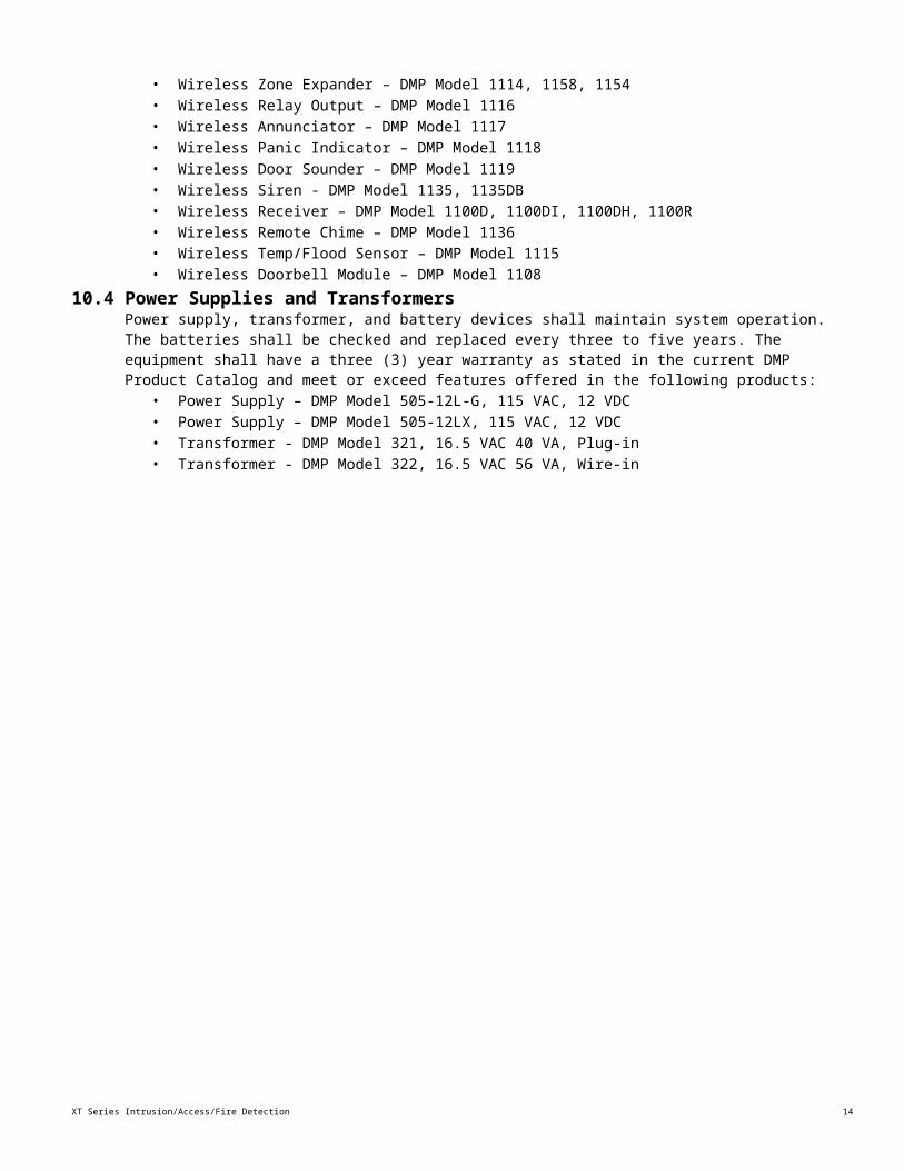
• Input transmitter – DMP Model 1101, 1102, 1107, 1131, 1106• Key Fob Panic Transmitter – DMP Model 1144-1-B, 1144-2-B, 1144-4-B, 1144-1-BP• Smoke Detector – DMP Model 1183-135F, 1183-135R, 1168, 1164• Carbon Monoxide Detector – 1184-W• Motion Detector – DMP Model 1127, 1122, 1126• Glass Break Detector – DMP Model 1128• Bill Trap – DMP Model 1139• Panic Transmitter – DMP Model 1142• Wireless Zone Expander – DMP Model 1114, 1158, 1154• Wireless Relay Output – DMP Model 1116• Wireless Annunciator – DMP Model 1117• Wireless Panic Indicator – DMP Model 1118• Wireless Door Sounder – DMP Model 1119• Wireless Siren - DMP Model 1135, 1135DB• Wireless Receiver – DMP Model 1100D, 1100DI, 1100DH, 1100R• Wireless Remote Chime – DMP Model 1136• Wireless Temp/Flood Sensor – DMP Model 1115• Wireless Doorbell Module – DMP Model 1108
10.4 Power Supplies and TransformersPower supply, transformer, and battery devices shall maintain system operation. The batteries shall be checked and replaced every three to five years. The equipment shall have a three (3)
XT Series Intrusion/Access/Fire Detection Specification
14
year warranty as stated in the current DMP Product Catalog and meet or exceed features offered in the following products:
• Power Supply – DMP Model 505-12L-G, 115 VAC, 12 VDC• Power Supply – DMP Model 505-12LX, 115 VAC, 12 VDC• Transformer - DMP Model 321, 16.5 VAC 40 VA, Plug-in• Transformer - DMP Model 322, 16.5 VAC 56 VA, Wire-in
15
XT Series Intrusion/Access/Fire Detection Specification
10.5 Door Control EquipmentDoor control equipment shall provide door control functions between the panel and controller door access points. The equipment shall have a three (3) year warranty as stated in the current DMP Product Catalog and meet or exceed features offered in the following products:
• Interface Module – DMP Model 734, Wiegand• Egress Module – DMP Model PB-2 REX Button• Reader – DMP Model PP-6005B ProxPoint Plus©• Reader – DMP Model MP-5365 Miniprox©• Reader – DMP Model MX-5375 Maxi-Prox™• Reader – DMP Model TL-5395 Thinline II™• Door Controller – DMP Model 1306P Prox Patch™• Door Controller – DMP Model 1306PW Prox Patch™• Access Card – DMP Model 1351 ProxPass© Card• Access Card – DMP Model 1326 Proxcard II© Card• Access Device – DMP Model 1346 Proxkey II™ Keyfob, 1386 Isoprox II©Farpointe Data:• Standard Light Prox Card – DMP Model PSC-1• Prox Key Ring Tag – DMP Model PSK-3• Imageable Prox Card – DMP Model PSM-2P• Cascade Proximity Reader – DMP Model P-300-H-A• Alps Proximity Reader – DMP Model P-500-H-A• Denali Proximity Reader – DMP Model P-620-H-A• Patagonia Proximity Reader & Keypad – DMP Model P-640-H-A• Contactless Smartcard Reader – DMP Model Delta3, Delta5 and Delta 6.4• MIFARE DesFire EV1 Smartcard – DMP Model DE2• Bluetooth Reader – DMP Model CSR-35P • Mobile Access Credential – DMP Model CMC-2
10.6 Z-Wave Wireless DevicesThe system shall be capable of 140 Z-Wave devices by means of the use of the model 738Z+ module. The following are compatible Z-Wave devices.
• 738Z Z-Wave Module• Z-TZEMT400BB3X Z-Wave Thermostat• Z-45602 Z-Wave Light Control Module with Dimmer• Z-45603 Z-Wave Light Control and Appliance Module• Z-99100-004 Z-Wave Door Deadbolt, Polished Brass• Z-99100-005 Z-Wave Door Deadbolt, Satin Nickel• Z-99100-006 Z-Wave Door Deadbolt, Venetian Bronze• Z-GD00Z Z-Wave Garage Door Controller
XT Series Intrusion/Access/Fire Detection Specification
16
11.0 INSTALLATION11.1System Component Installation
A. When used in NFPA 72 compliant installations, the Intrusion Detection/ Door Control or Household Fire Warning System shall be on an electrical circuit dedicated branch in accordance with the National Electrical Code (NEC) and the local authority having jurisdiction (AHJ).B. Materials shall be installed in strict compliance with all local, state, county, province, district, federal and other applicable building, safety, and fire standards, laws, codes, regulations, and guidelines including, but not limited to, all appendices and amendments and the requirements of the local authority having jurisdiction (AHJ).
17
XT Series Intrusion/Access/Fire Detection Specification
12.0 SYSTEM COMPARISON12.1Basic Comparison Items Table
The table below lists features or points found necessary for successful installation and continued service of an integrated system. Compare your current system with the listed items. Please provide a certification document providing a clear and truthful statement that agrees with your response to each question.
Important Points Explanation ResponseMade in USA Is your system engineered, designed, manufactured, assembled,
and distributed from a location within the United States of America using U.S. and global components?
Yes No
Forward and Backward compatibility
Because we want to preserve a maximum portion of our investment over time, can your system manufacturer certify that it has practiced forward and backward compatibility of main system components such as the panel, keypads, zone expansion devices, and relay output devices for a minimum of the last twenty (20) years?
Yes No
Manufacturer Experience
Because we require extensive manufacturing experience, has your system controller manufacturer’s primary role been in the security industry for a minimum of thirty (30) years?
Yes No
System Messaging Compatibility
We require the maximum capabilities in communication offered by the manufacturer. Does your system controller manufacturer also engineer, and manufacture a receiver that receives all messages in less than six seconds? If so, can this receiver receive each and every status message that the controller sends?
Yes No
Experience in Network Monitoring
Has your manufacturer been providing TCP/IP network monitoring for a minimum of fifteen (15) years?
Yes No
Proven success in Network monitoring capabilities.
Does your manufacturer have at least 15,000 installed systems which use network monitoring to report messages by way of a TCP/IP network?
Yes No
No Invasive systems on our network
Because our network is so important to the operation of our business, we require that no additional PCs or terminals be allowed upon our network. Does your manufacturer require additional software or PC terminals in order to program or maintain operation of network monitoring functions?
Yes No
Network monitoring flexibility and compliance
Because we require confirmation of the fitness of your monitoring capabilities, the system must be listed by approved compliance agencies. Can your manufacturer’s controller provide network monitoring over a network that uses DHCP, NAT, or a static IP address?
Yes No
Easy operation Because we manage so many people, the system must be easy to operate. Does your system manufacturer offer keypads with integrated proximity identification capabilities?
Yes No
Seamless Integration with Access Control
Because we are aware of false alarm activations that may occur when using a security system and access control system, we require that these two systems be designed into one control panel. Does your system offer intrusion detection and door access control functions that allow the user to disarm selected areas, and open an access door with a single presentation of a proximity identification device?
Yes No
Distribution of relay outputs
Because we intend to integrate this system with many of our other electronic systems within the building, we require that the placement of triggering relays be as flexible as possible. Does your system have the ability to provide relay outputs in a central location, and distributed across a data bus which extends at least 15,000 feet?
Yes No
INTEGRATED SECURITY SYSTEM PERFORMANCE SPECIFICATION FOR DMP MODEL XT SERIES™ CONTROL PANELS
Important Points Explanation ResponseRelay triggering capabilities
Because we intend to integrate this system with many of our other electronic systems within the building, we require that the triggering of relays be as flexible as possible. Can your system trigger relay outputs based upon zone status or system status, and can relays be triggered by way of keypad commands, software commands, Web browser commands, RF remote, and a pre-determined schedule?
Yes
No
Relay states when triggered
Because we intend to integrate this system with many of our other electronic systems within the building, we require that the triggering of relays be as flexible as possible. Can your system’s relay outputs be selected for status to follow zone input status, pulsed output, and maintained outputs?
Yes
No
Relay states according to the state of the zone input
Because we intend to integrate this system with many of our other electronic systems within the building, we require that the triggering of relays be as flexible as possible. Can your system’s relay outputs be configured for different responses based upon the armed state of the zone?
Yes
No
Relay associations to zones based upon system and zone states.
Because we intend to integrate this system with many of our other electronic systems within the building, we require that the triggering of relays be as flexible as possible. Can you assign different relays for each zone based upon whether the system is armed and the zone is open, the system is disarmed and the zone is open, the system is armed and the zone is shorted, and the system is disarmed and the zone is shorted?
Yes
No
Common descriptions for zone, area, and user designations.
Because we wish to minimize confusion in various ways that we use reporting, we require that descriptions for areas of our building, users of the system, and zone inputs connected to the system offer at least sixteen (16) characters to maximize user understanding. These descriptions must be programmed and stored in one location, and appear exactly the same in stored events, printed logs, and appear remotely at the central monitoring station. Does your system provide this capability?
Yes
No
Flexible user interface capabilities
Because we may use the system from many locations, in many ways, we require that the system offer user interface capabilities from local keypads, web browsers, software packages, radio frequency remote arming stations, and must also offer the capability to use any zone input for arming and disarming. Does your system offer all of these capabilities?
Yes
No
Economical system additions for access control
Because we are looking for a cost-competitive system design, the system shall be capable of adding up to five (5) door access locations without requiring additional control panels. To minimize cabling costs, the system wiring must support a single four-wire cable to connect up to five(5) doors, and must use remote intelligent devices to collect door status, user identification devices, and triggers to unlock distant doors. Does your system offer this capability?
Yes
No
Contractor experience
Because we require that the installing company is experienced and factory trained. We require each installer and service person who works on our system to be factory trained and must submit a certificate issued by the factory as proof of this training. Can your company provide these certification documents?
Yes
No
LT-0992 20073 © 2020 Digital Monitoring Products, Inc.


![Humanitarian OpenStreetMap Team [H.O.T.] Activations](https://img.pdfslide.us/doc/110x75/558c72bdd8b42a65098b46a0/humanitarian-openstreetmap-team-hot-activations.jpg)