Embed Size (px)
Citation preview
Integrated Resources Management in Asian Cities: The Urban NEXUS
South-East Asia
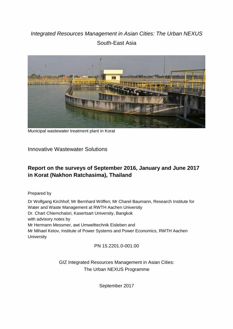
Municipal wastewater treatment plant in Korat
Innovative Wastewater Solutions
Report on the surveys of September 2016, January and June 2017
in Korat (Nakhon Ratchasima), Thailand
Prepared by
Dr Wolfgang Kirchhof; Mr Bernhard Wöffen; Mr Charel Baumann, Research Institute for
Water and Waste Management at RWTH Aachen University
Dr. Chart Chiemchaisri, Kasertsart University, Bangkok
with advisory notes by
Mr Hermann Messmer, awt Umwelttechnik Eisleben and
Mr Mihael Ketov, Institute of Power Systems and Power Economics, RWTH Aachen
University
PN 15.2201.0-001.00
GIZ Integrated Resources Management in Asian Cities:
The Urban NEXUS Programme
September 2017

Innovative Wastewater Solutions for Korat (Nakhon Ratchasima), Thailand
170726-Report_on_Korat 2
Author with main contributions: Dipl.-Ing. Bernhard Wöffen Research Institute for Water and Waste Management at RWTH Aachen University (FiW) Kackertstr. 15-17, D-52056 Aachen, Germany E-Mail: [email protected]
Supervising author: Dr.-Ing. Wolfgang Kirchhof (FiW) Tel.: +49-241-8026828 E-Mail: [email protected] www.fiw.rwth-aachen.de

Innovative Wastewater Solutions for Korat (Nakhon Ratchasima), Thailand
170726-Report_on_Korat 3
Table of contents
Table of contents ............................................................................................................... 3
0 EXECUTIVE SUMMARY ................................................................................... 9
1 INTRODUCTION ............................................................................................. 13
1.1 Overall Background ......................................................................................... 13
1.2 Structure of the study ....................................................................................... 14
1.3 Methodology of the study ................................................................................. 14
2 FINDINGS of SEPTEMBER 2016 SURVEY on the MUNICIPAL WWTP
KORAT ............................................................................................................ 17
2.1 Basic data on Korat .......................................................................................... 17
2.2 Observations and Results in September 2016 ................................................. 17
2.3 Calculation of the capacity of the wastewater treatment plant Korat ................. 22
2.3.1 Calculation of the aerobic sludge system’s capacity ......................................... 22
2.4 RECOMMENDATIONS based on the findings of the visit in Sept. 2016 ........... 23
2.4.1 Concept for the rehabilitation of the treatment plant ......................................... 23
2.4.2 Short-term measures ....................................................................................... 24
2.4.3 Intermediate term measures ............................................................................ 28
2.4.4 Long-term measures ........................................................................................ 29
3 FINDINGS of JUNE 2017 SURVEY on the MUNICIPAL WWTP KORAT ......... 31
3.1 General remarks .............................................................................................. 31
3.2 Findings in pumping stations P 1, P 2.1 and P2.2 ............................................ 31
3.3 Findings in wwtp 1 – 3 ..................................................................................... 36
3.3.1 Findings at wwtp 1 ........................................................................................... 38
3.3.2 Findings at wwtp 2 ........................................................................................... 40
3.3.3 Findings at wwtp 3 ........................................................................................... 42
3.4 RECOMMENDATIONS to improve the Wastewater Treatment Plant ............... 44
3.4.1 Preamble and clarifications .............................................................................. 44
3.4.2 Improvement of the measuring and analysis system of the wwtp ..................... 44
3.4.3 Improvement of safety and working conditions ................................................. 46
3.4.4 Improvement of the budget system .................................................................. 46

Innovative Wastewater Solutions for Korat (Nakhon Ratchasima), Thailand
170726-Report_on_Korat 4
3.4.5 Reversal of wastewater flow ............................................................................ 46
3.4.6 Recommended action plan to restart the main wastewater treatment plant
in Korat ............................................................................................................ 48
3.4.7 Active sludge management .............................................................................. 48
3.4.8 Options for a sustainable operation of the wastewater treatment plant
operation .......................................................................................................... 49
3.5 Annotation for the repair of the travelling bridges of the rectangular tanks of
wwtp 1 and wwtp 2 .......................................................................................... 50
3.6 Annotation to the change of flow direction and the new distributor to feed
wwtp 1 / 2 ........................................................................................................ 52
3.7 Annotation to the use of the pond area for the installation of a Photo voltaic
plant ................................................................................................................. 58
4 FINDINGS of the September 2016 survey on the NEW DEVELOPMENT ZONE 7
KORAT .......................................................................................................................... 60
4.1 Water management structures of Zone 7 60
4.2 Conceptual recommendations for the wastewater management in Zone 7 63
4.2.1 Short-term corrective measures of the combined sewer outfalls ...................... 63
4.2.2 Short-term protection measures of the natural river against run-off water ........ 64
4.3 Intermediate term measures for the wastewater management 65
4.3.1 Development of an integrated urban drainage plan (Master Plan) .................... 65
4.3.2 Recommendations for an integrated urban drainage plan for zone 7,
focusing on decentralized measures ................................................................ 67
5 ANNEXES ..................................................................................................................... 68
Innovative Wastewater Solutions for Korat (Nakhon Ratchasima), Thailand
170726-Report_on_Korat 5
List of Figures
Figure 1: Members of the survey team conducted the survey in September 2016 .......... 14
Figure 2: Members of the survey team that conducted the survey in June, 2017 ............ 14
Figure 3: Overview map of the main survey areas in Korat, 1 = wastewater treatment
plant, 2 = new development zone .................................................................... 15
Figure 4: Sewer network of Korat with location of the pumping stations to the
wastewater treatment plant consisting of nine ponds and three aerated
wastewater plants ............................................................................................ 18
Figure 5: Wastewater treatment plant of Korat with main pumping stations (P 1, P
21,P 2.2) , pond inlet structure (I 1 – 3) and aerated biological treatment
systems (wwtp 1 – 3) ....................................................................................... 19
Figure 6: Municipal wastewater treatment plant in Korat ................................................. 19
Figure 7: Plan of sewer sewerage system to the wwtp (left) and flow through scheme
in the wwtp ....................................................................................................... 20
Figure 8: Aeration basin and sedimentation basin of wwtp line 1 .................................... 21
Figure 9: Travelling bridge with four suction scrapers of the first wwtp line ..................... 21
Figure 10: Dimension of the wastewater treatment process, including aeration tank
and sedimentation basin .................................................................................. 22
Figure 11: Korat Wastewater Treatment Plant with reversed wastewater flow .................. 24
Figure 12: Photos of the last two pumping stations before the pond system ..................... 24
Figure 13: Photos of the geared guiding tracks from a functioning wwtp ........................... 25
Figure 14: Photo of a correctly dimensioned travelling bridge from a functioning wwtp ..... 26
Figure 15: Field equipment for Analysis of sludge volume and settleable solid content ..... 27
Figure 16: Overview photo of Korat wwtp with indicated area for a vacuum sewer
system ............................................................................................................. 28
Figure 17: Photo of a sludge humification system (Left), area of the korat wwtp area
needed for sludge humidification (right) ........................................................... 29
Figure 18: Overview of wastewater flow and main pipes and main pumping stations to
the ponds ......................................................................................................... 32
Figure 19: Korat wastewater pumping station 1 at road Soi Taosura 2 ............................. 32
Figure 20: Example of performance curve for new Corman-Rupp pump Type
T10C60SC-B (2017) ........................................................................................ 33

Innovative Wastewater Solutions for Korat (Nakhon Ratchasima), Thailand
170726-Report_on_Korat 6
Figure 21: Electrodes for flow-measurement at the pipes to the collecting shaft ............... 34
Figure 22: Korat wastewater pumping stations to feed the ponds (P 2.2 left photos,
P 2.1 right side photos) .................................................................................... 35
Figure 23: Corrosion at pipes and concrete in the collection shaft from P 2.1 and P 2.2
(photos from top) ............................................................................................. 36
Figure 24: Principle aeration basin, recycle sludge pumps, surplus sludge pumps ........... 37
Figure 25: Principle sedimentation basin with traveling bridges ........................................ 37
Figure 26: Wwtp 1: Aeration basin, bubble test, damaged rail of sedimentation basin,
automatic sensor, sampling equipment, broken stop switch ............................. 38
Figure 27: Wwtp 2: Aeration basin, recycle sludge pumps, surplus sludge pumps,
operstor with grease gun, sedimentation basin with traveling bridges .............. 40
Figure 28: 20 ml/l Biomass in the aeration basin after one day operation of wwtp 2 ......... 41
Figure 29: Wwtp3: Main inlet power switch, sedimentation basin with traveling bridges,
door of machinary house, broken rails, broken cable lift ffor of stirrer,
damaged rail .................................................................................................... 42
Figure 30: Wastewater Measurement electrode – types ................................................... 46
Figure 31: Korat Wastewater Treatment Plant with reversed wastewater flow .................. 47
Figure 32: Example of a new distributor to Korat Wastewater Treatment Plant ................. 47
Figure 33: Hand drawing of the guding and rollng side of a traveling bridge .................... 50
Figure 34: Chronological order of changing flow direction ................................................ 53
Figure 35: Formal outline of the distributor for feed of wwtp 1 + 2 .................................... 55
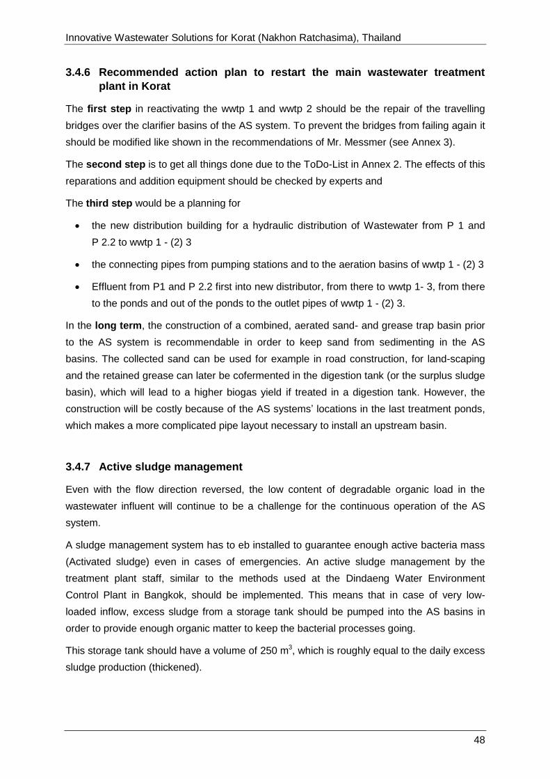
Figure 36: Section A-A of the distributor ........................................................................... 56
Figure 37: Section B-B of the distributor ........................................................................... 56
Figure 38: Aerial view of the development zone 7 in Korat ................................................ 60
Figure 39: Sketch of development zone 7 with existing sewer net work ............................ 60
Figure 40: Photos of various land uses, (agriculture) in the development zone 7 ............. 61
Figure 41: Photos of various river sections (weir, natural river bank, level measuring
device, information plate of RID8) in the development zone 7 .......................... 61
Figure 42: Wastewater facilities in Zone 7, left: decentralised treatment system, right:
Waterflow under combined sewer overflow pipe .............................................. 62
Figure 43: Sketch of the Development Zone 7, with indicated spots of the combined
sewer (drainage) overflows and the natural river (green belt) ........................... 62

Innovative Wastewater Solutions for Korat (Nakhon Ratchasima), Thailand
170726-Report_on_Korat 7
Figure 44: Photo of a retention basin with filter unit at the outlet point (www.
https://sustainablestormwater.org) ................................................................... 64
Figure 45: Schemes of run-off water treatment systems using sand filtrations and
constructed wet lands ...................................................................................... 64
Figure 46: Photos of installed run-off water treatment systems using sand filtrations
and constructed wet lands (Kirchhof, 2012) ..................................................... 65
Figure 47: Core elements and topics of an integrated urban drainage planning by
DWA ................................................................................................................ 66
Figure 48: Concept for developments in the Development Zone 7, with indicated
development topics .......................................................................................... 67
List of Tables
Table 1 Measured electric currency for aerators and recycle pumps (as a hint for
maintenance) ..................................................................................................... 41
Table 2 Hydraulic losses and needed length of the pipes from in the distributor ..............53
Table 3 Estimated masses and costs for changing the flow direction ..............................57
Table 4 Technical input and output data for the PV plant on the wwtp area in Korat ........59
Annexes
Annex 1: Checklists of the pumping stations P1, P 2.1, P 2.2 and wwtp 1 - 3
Annex 2: General To Do – List
Annex 3: Special recommendations to traveling bridges from Mr. Messmer AWT
Annex 4: Calculation matrix to calculate basic data for a PV-plant

Innovative Wastewater Solutions for Korat (Nakhon Ratchasima), Thailand
170726-Report_on_Korat 8
List of Abbreviations
Abbreviation Explanation
AS Activated Sludge
BOD5 Biochemical Oxygen Demand within five days
COD Chemical Oxygen Demand
DWA German Water Association
EPB Environmental Protection Bureau
FOG Fat, oil and grease
MBAS Methylene blue active substances
MLSS Mixed liquor suspended solids
O&M Operation and Maintenance
oTS Organic dry matter
SBR Sequencing Batch Reactor
SS Suspended solids
ToR Terms of Reference
TDS Total Dissolved Solids
TKN Total Kjeldahl-Nitrogen is the sum of organic nitrogen and Ammonium
(NH4+) in an analysis sample
TP total phosphor
VS Vacuum station
WWTP Wastewater Treatment Plant
Innovative Wastewater Solutions for Korat (Nakhon Ratchasima), Thailand
170726-Report_on_Korat 9
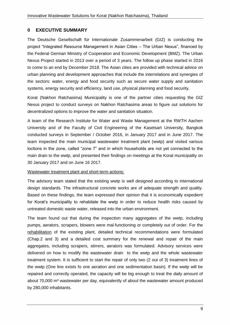
0 EXECUTIVE SUMMARY
The Deutsche Gesellschaft für Internationale Zusammenarbeit (GIZ) is conducting the
project “Integrated Resource Management in Asian Cities – The Urban Nexus”, financed by
the Federal German Ministry of Cooperation and Economic Development (BMZ). The Urban
Nexus Project started in 2013 over a period of 3 years. The follow up phase started in 2016
to come to an end by December 2018. The Asian cities are provided with technical advice on
urban planning and development approaches that include the interrelations and synergies of
the sectors: water, energy and food security such as secure water supply and sanitation
systems, energy security and efficiency, land use, physical planning and food security.
Korat (Nakhon Ratchasima) Municipality is one of the partner cities requesting the GIZ
Nexus project to conduct surveys on Nakhon Ratchasima areas to figure out solutions for
decentralized options to improve the water and sanitation situation.
A team of the Research Institute for Water and Waste Management at the RWTH Aachen
University and of the Faculty of Civil Engineering of the Kasetsart University, Bangkok
conducted surveys in September / October 2016, in January 2017 and in June 2017. The
team inspected the main municipal wastewater treatment plant (wwtp) and visited various
loctions in the zone, called “zone 7” and in which households are not yet connected to the
main drain to the wwtp, and presented their findings on meetings at the Korat municipality on
30 January 2017 and on June 16 2017.
Wastewater treatment plant and short-term actions:
The advisory team stated that the existing wwtp is well designed according to international
design standards. The infrastructural concrete works are of adequate strength and quality.
Based on these findings, the team expressed their opinion that it is economically expedient
for Korat’s municipality to rehabilate the wwtp in order to reduce health risks caused by
untreated domestic waste water, released into the urban environment.
The team found out that during the inspection many aggregates of the wwtp, including
pumps, aerators, scrapers, blowers were mal-functioning or completely out of order. For the
rehabilitation of the existing plant, detailed technical recommendations were formulated
(Chap.2 and 3) and a detailed cost summary for the renewal and repair of the main
aggregates, including scrapers, stirrers, aerators was formulated. Advisory services were
delivered on how to modify the wastewater drain to the wwtp and the whole wastewater
treatment system. It is sufficient to start the repair of only two (2 out of 3) treatment lines of
the wwtp (One line exists fo one aeration and one sedimentation basin). If the wwtp will be
repaired and correctly operated, the capacity will be big enough to treat the daily amount of
about 70,000 m³ wastewater per day, equivalently of about the wastewater amount produced
by 280,000 inhabitants.

Innovative Wastewater Solutions for Korat (Nakhon Ratchasima), Thailand
170726-Report_on_Korat 10
The cost for the repair works are estimated as follows:
Wwtp line 1: 3,600,000 Baht (91,700 EUR)
Wwtp line 2: 3,300,000 Baht (84,100 EUR)
Good process control: The advisory team found out that the process control has severe
faults and formulated recommendations on how to upgrade the technical analysis and
monitoring systems (Chap.3). Beside the technical upgrade, it is advisable to improve
knowledge and capabilities for the supervising and operational staff by a “tailor-made”
training programme.
Budget for Operation and Maintenance (O&M): The team found out that the fund allocation
for the O&M is not sufficient, it is urgently necessary to install an annual budget for the O&M
works in order to avoid severe damages. In cases of emergencies, this budget the plant
operatorional staff will in time be enabled to start repair actions and to avoid interruptions of
the wwtp operation.
Wastewater treatment plant and middle-term actions:
The team has noted that the existing wwtp is designed and capable to treat more hazardous
substances as in the situation found during the survey The existing plant could be operated
more efficiently: It is recommended to look on a measure on how the increase the
wastewater load in the inlet drain. It is recommended to connect households directly to the
wastewater treatment plant, e.g by connecting houses using a vacuum sewer system.
Decentralized options for the development zone “7”:
For the services of the city development “zone 7” conceptual recommendations were
formulated, pointing out high potentials for the development of decentralized wastewater
systems in zone 7. The team found out that untreated wastewater from the main waste water
collector could be discharged into the river. It is recommended to collect this wastewater in
retension basins and treat it before the release into the river. Open and or agricultural areas
are available and could be used to install nature-near wastewater treatment plants, such as
vertically or horizontally flown-through root filter systems. After the treatment this water could
be used as irrigation water for the agricultural areas.Decentralized systems have to be
maintained and monitored by operational staff of the municipality. It is advisable to conduct a
study on how municipal waste water management and agricultural land management could
be combined regarding the different responsibilities of the municipality and agricultural
departments.
Innovative Wastewater Solutions for Korat (Nakhon Ratchasima), Thailand
170726-Report_on_Korat 11
Wastewater treatment plant and long-term actions:
The team confirmed that after the rehabilitation of two out of three lines the wwtp will met the
requirements and that there will be a significant part of the existing pond area, which will not
be used for the treatment process. Estimately of about 270 000 m² of the pond area that can
be used for other city development projects.
The team estimated the benefit of this idle area, if this area is used for the implementation
and operation of a photovoltaic plant for the generation of electrical energy (Chap.3).
Regarding the local physical and climatic conditions, the team assessed that it is technically
and economically feasible to install a PV plant of 38 MWp and to produce about 50 000
MWh/a of electrical power.

Innovative Wastewater Solutions for Korat (Nakhon Ratchasima), Thailand
170726-Report_on_Korat 12
Empty page

Innovative Wastewater Solutions for Korat (Nakhon Ratchasima), Thailand
170726-Report_on_Korat 13
1 INTRODUCTION
1.1 Overall Background
The German Agency for International Cooperation (GIZ) is conducting the project “Integrated
Resource Management in Asian Cities – The Urban Nexus”, starting from 2013 over a period
of 3 years. Selected Asian cities are provided with technical advice on urban planning and
development approaches that include the interrelations and synergies of the sectors: water,
energy and food security such as secure water supply and sanitation systems, energy
security and efficiency, land use, physical planning and food security.
Moreover, knowledge and experience sharing and cooperation between public, private and
civil-society stakeholders is essential. Strategically, the project focuses on two core
elements. On the one hand, nexus initiatives demonstrate in an exemplary way how to
integrate the nexus approach into urban planning and development processes. On the other
hand, the regional exchange and dissemination of successful practical approaches to
integrated resource management is undertaken through efficient networking.
Nakhon Ratchasima (Korat) Municipality in Thailand is one of the Nexus Partner cities
requesting the GIZ Nexus project to conduct a study on integrated wastewater management
and waste management in Korat. The key objective was to analyze the situation and to find
potentials for innovative improvements. Preliminary results and findings are summarized in
the report “Wastewater management and organic waste management in Korat/ Thailand”,
prepared by Fraunhofer IGB in March 2014 for the Regional NEXUS project.
In July 2016 on behalf of GIZ, a follow-up study was commissioned to develop innovative
semi and decentralized solutions for the wastewater treatment regarding water reuse options
and energy saving option for the municipal wastewater treatment plant Korat and for the New
Development zone in Korat. Main topics of this study were development of appropriate,
innovative, semi and decentralized solutions for the treatment of municipal wastewater
regarding options for the generation of alternative water resources, water reuse.
The consultancy comprised a preparatory work phase in Germany, a short-term mission of
an international and a national expert team from September 28 to September 30, 2016 to
Nakhon Ratchasima, and an assessment work phase afterwards. On January 30, 2017,
preliminary results of the study were presented at the municipality in Nakhon Ratchasima.
Another study mission thereafter took place from June 13 to June 16, 2017 and was focused
on the rehabilation of the waste water treatment plant and the assessment of potentials after
the implementation of the recommended rehabilitation measures.
Innovative Wastewater Solutions for Korat (Nakhon Ratchasima), Thailand
170726-Report_on_Korat 14
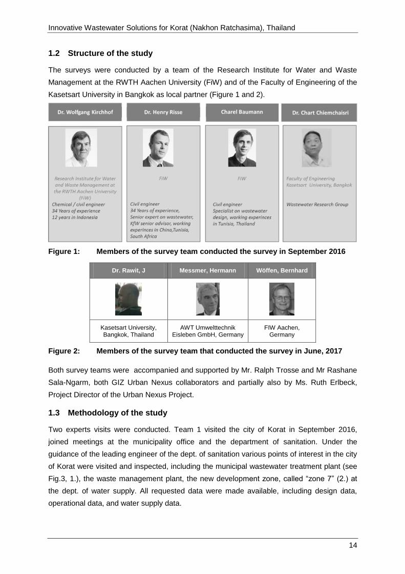
1.2 Structure of the study
The surveys were conducted by a team of the Research Institute for Water and Waste
Management at the RWTH Aachen University (FiW) and of the Faculty of Engineering of the
Kasetsart University in Bangkok as local partner (Figure 1 and 2).
Figure 1: Members of the survey team conducted the survey in September 2016
Dr. Rawit, J Messmer, Hermann Wöffen, Bernhard
Kasetsart University, Bangkok, Thailand
AWT Umwelttechnik Eisleben GmbH, Germany
FIW Aachen, Germany
Figure 2: Members of the survey team that conducted the survey in June, 2017
Both survey teams were accompanied and supported by Mr. Ralph Trosse and Mr Rashane
Sala-Ngarm, both GIZ Urban Nexus collaborators and partially also by Ms. Ruth Erlbeck,
Project Director of the Urban Nexus Project.
1.3 Methodology of the study
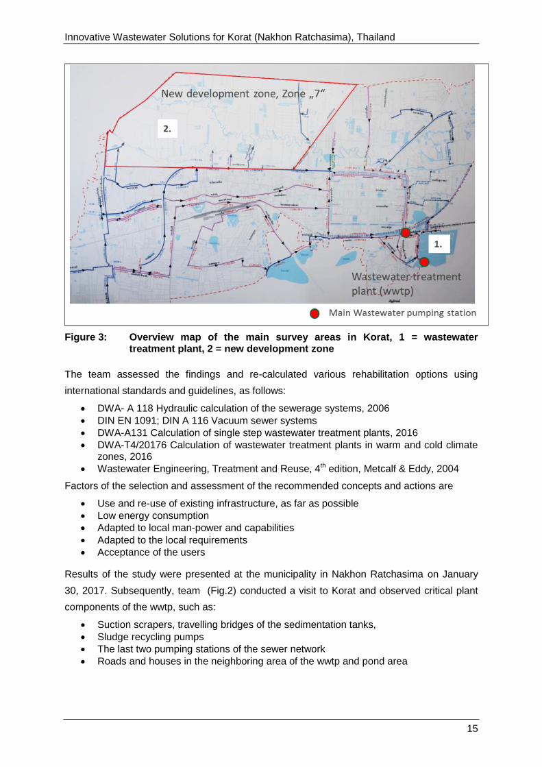
Two experts visits were conducted. Team 1 visited the city of Korat in September 2016,
joined meetings at the municipality office and the department of sanitation. Under the
guidance of the leading engineer of the dept. of sanitation various points of interest in the city
of Korat were visited and inspected, including the municipal wastewater treatment plant (see
Fig.3, 1.), the waste management plant, the new development zone, called “zone 7” (2.) at
the dept. of water supply. All requested data were made available, including design data,
operational data, and water supply data.
Innovative Wastewater Solutions for Korat (Nakhon Ratchasima), Thailand
170726-Report_on_Korat 15
Figure 3: Overview map of the main survey areas in Korat, 1 = wastewater treatment plant, 2 = new development zone
The team assessed the findings and re-calculated various rehabilitation options using
international standards and guidelines, as follows:
DWA- A 118 Hydraulic calculation of the sewerage systems, 2006
DIN EN 1091; DIN A 116 Vacuum sewer systems
DWA-A131 Calculation of single step wastewater treatment plants, 2016
DWA-T4/20176 Calculation of wastewater treatment plants in warm and cold climate zones, 2016
Wastewater Engineering, Treatment and Reuse, 4th edition, Metcalf & Eddy, 2004
Factors of the selection and assessment of the recommended concepts and actions are
Use and re-use of existing infrastructure, as far as possible
Low energy consumption
Adapted to local man-power and capabilities
Adapted to the local requirements
Acceptance of the users
Results of the study were presented at the municipality in Nakhon Ratchasima on January
30, 2017. Subsequently, team (Fig.2) conducted a visit to Korat and observed critical plant
components of the wwtp, such as:
Suction scrapers, travelling bridges of the sedimentation tanks,
Sludge recycling pumps
The last two pumping stations of the sewer network
Roads and houses in the neighboring area of the wwtp and pond area

Innovative Wastewater Solutions for Korat (Nakhon Ratchasima), Thailand
170726-Report_on_Korat 16
More details on the construction of the plant components were made available. Based on
these information, the team discussed in more details on how to improve the performance of
the wastewater treatment system.
Innovative Wastewater Solutions for Korat (Nakhon Ratchasima), Thailand
170726-Report_on_Korat 17
2 FINDINGS of SEPTEMBER 2016 SURVEY on the MUNICIPAL WWTP
KORAT
2.1 Basic data on Korat
Nakhon Ratchasima (Thai: นครราชสีมา), commonly known as Korat (โคราช), is one of the four
major cities of Isan, the central-eastern region of Thailand. Korat is at the western edge
(elevation of about 200 m,) of the Korat Plateau, about 250 km north-east of Bangkok. It is
the governmental seat of the Nakhon Ratchasima Province and Nakhon Ratchasima District.
As of 2010, the municipal area had a population of 142,645. In 2013 Korat has 173,000
registered inhabitants. As many people lived as “unregistered” in the city, the total population
is estimated with 250,000 inhabitants.
The annual rainfall amount is about 1,500 mm. Most rainfall (rainy season) is seen from May
to October (see diagrams in Annex 5). Korat has a dry period from December to February.
On average, the warmest month is April, the coolest month is December. During rainy
season flooding due to heavy rain occurs frequently. During the dry season water becomes
scarce, limiting the agricultural production.
About 90 % of the population is connected to a combined sewer system, the outer districts,
including the “zone 7” are not yet connected, (end of 2016). Private houses are equipped
with septic tanks, overflows of which are connected by pipes to open sewer systems, which
are connected to the main wastewater discharge pipe system. As by the sewer system
already treated household wastewater and surface run-off water during the rainy season is
collected, the pollution load of the wastewater is lower than in industrialized countries, such
as Germany, where nearly only closed pipe systems are used for the sewage collection
systems.
2.2 Observations and Results in September 2016
An overview plan of the sewer system of Korat, provided by the municipality, is shown in
Figure 4. The information available is very scarce, as only the main pipes, overflows and
pumping stations are shown.
Innovative Wastewater Solutions for Korat (Nakhon Ratchasima), Thailand
170726-Report_on_Korat 18
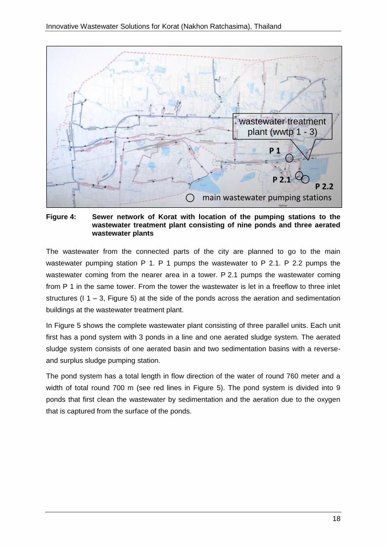
Figure 4: Sewer network of Korat with location of the pumping stations to the wastewater treatment plant consisting of nine ponds and three aerated wastewater plants
The wastewater from the connected parts of the city are planned to go to the main
wastewater pumping station P 1. P 1 pumps the wastewater to P 2.1. P 2.2 pumps the
wastewater coming from the nearer area in a tower. P 2.1 pumps the wastewater coming
from P 1 in the same tower. From the tower the wastewater is let in a freeflow to three inlet
structures (I 1 – 3, Figure 5) at the side of the ponds across the aeration and sedimentation
buildings at the wastewater treatment plant.
In Figure 5 shows the complete wastewater plant consisting of three parallel units. Each unit
first has a pond system with 3 ponds in a line and one aerated sludge system. The aerated
sludge system consists of one aerated basin and two sedimentation basins with a reverse-
and surplus sludge pumping station.
The pond system has a total length in flow direction of the water of round 760 meter and a
width of total round 700 m (see red lines in Figure 5). The pond system is divided into 9
ponds that first clean the wastewater by sedimentation and the aeration due to the oxygen
that is captured from the surface of the ponds.
P 1
P 2.1
main wastewater pumping stations
P 2.2
wastewater treatment plant (wwtp 1 - 3)

Innovative Wastewater Solutions for Korat (Nakhon Ratchasima), Thailand
170726-Report_on_Korat 19
Figure 5: Wastewater treatment plant of Korat with main pumping stations (P 1, P 21,P 2.2) , pond inlet structure (I 1 – 3) and aerated biological treatment systems (wwtp 1 – 3)
The municipal wwtp Korat is based on a pond system (with an overall area of 120,000 m²,
built in 1990’s and an activated sludge plant, which in 2009 was integrated into the pond
area, designed for a flow of 75,000 m³/d. It is reported that during the rainy season the flow
is about 60,000 m³ and during the dry season of about 30,000 m³/day.
Figure 6: Municipal wastewater treatment plant in Korat
The technical wwtp, designed for a flow of 75,000 m³/d, was foreseen to treat the effluent of
the pond system. The collected waste water, coming from the city area is lifted by a pumping
station into the pond system and flows through the pond system in three parallel lines before
it is treated in the wwtp.
P 1
P 1, P2.1 and P.2.2: main wastewater pumping stations
P 2.2
wwtp 1
P 2.1
wwtp 2 wwtp 3
I 1 I 2
I 3
I 1, I2 and I3: inlet shafts

Innovative Wastewater Solutions for Korat (Nakhon Ratchasima), Thailand
170726-Report_on_Korat 20
Figure 7: Plan of sewer sewerage system to the wwtp (left) and flow through scheme in the wwtp
The Municipal wastewater treatment plant in Korat is underloaded.
As described in the preliminary studies, it is evident, that the organic load in the influent of
the activated sludge system is not sufficient to generate enough biomass for the system to
work properly. This is due to the degradation processes in the upstream treatment ponds and
especially due to the septic tanks in use on most housing and commercial plots in the
city.The water quality parameter measured in the influent and effluent of the wwtp system
indicates that the technical wwtp is critically underloaded. BOD, COD and TKN were
measured by the team in October:
Inlet BOD 23.5 – 25.9 mg/L
Inlet COD 46.9 – 54.3 mg/L
Inlet TKN 8.1 – 11.5 mg/L
Due to the COD/BOD ratio of 2,0 – 2.2 (54,3/25,9) it could be stated that the incoming
wastewater can be treated with the activated sludge process, but as the organic loaded,
expressed as low COD-load, is very low, the bacterial degradation rate of the activated
sludge process will be low. Due to this fact, the production of the activated sludge will remain
low. So there should be taken some pre-caution measures to avoid the loss of the activated
sludge in the basins, (if the process is running again).
Innovative Wastewater Solutions for Korat (Nakhon Ratchasima), Thailand
170726-Report_on_Korat 21
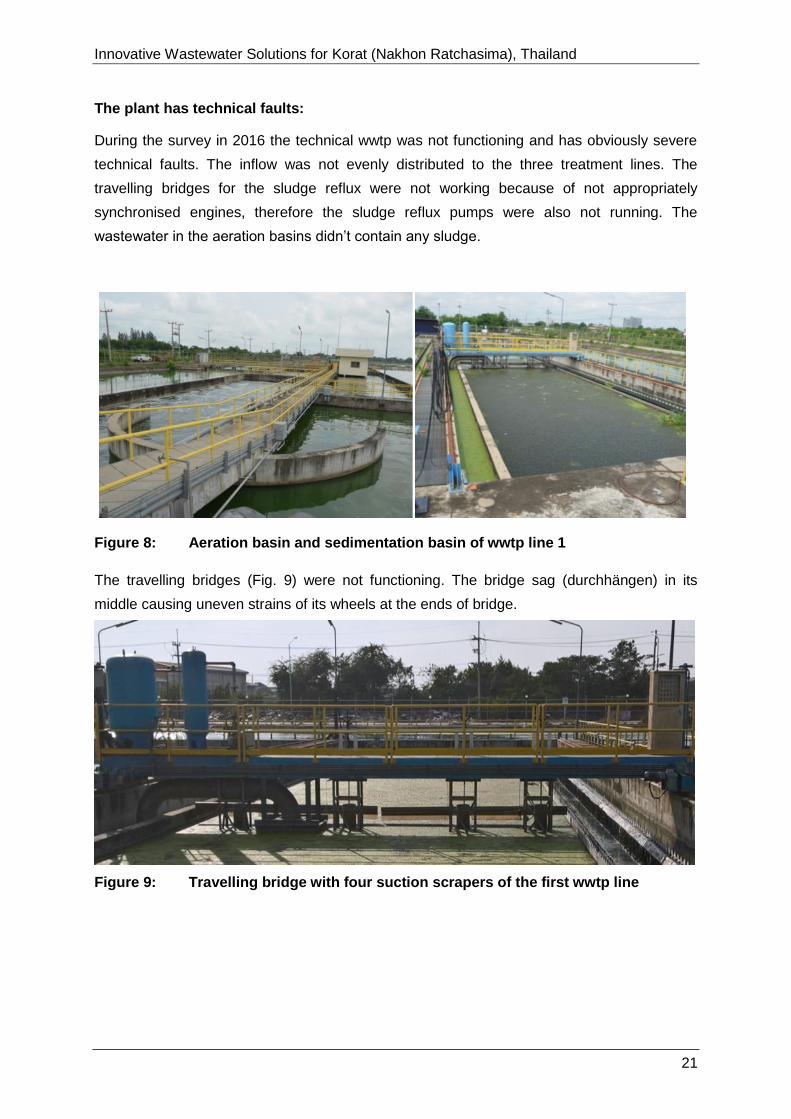
The plant has technical faults:
During the survey in 2016 the technical wwtp was not functioning and has obviously severe
technical faults. The inflow was not evenly distributed to the three treatment lines. The
travelling bridges for the sludge reflux were not working because of not appropriately
synchronised engines, therefore the sludge reflux pumps were also not running. The
wastewater in the aeration basins didn’t contain any sludge.
Figure 8: Aeration basin and sedimentation basin of wwtp line 1
The travelling bridges (Fig. 9) were not functioning. The bridge sag (durchhängen) in its
middle causing uneven strains of its wheels at the ends of bridge.
Figure 9: Travelling bridge with four suction scrapers of the first wwtp line

Innovative Wastewater Solutions for Korat (Nakhon Ratchasima), Thailand
170726-Report_on_Korat 22
2.3 Calculation of the capacity of the wastewater treatment plant Korat
The capacity of the existing wastewater treatment plant was calculated using international
design standards and, if necessary, by chosing asumptions based on the team’s experts’
experiences.
2.3.1 Calculation of the aerobic sludge system’s capacity
Using the as-built drawings, surface areas, volumes, and depths of the aeration and
sedimentation tanks were calculated, as shown in Fig.10.
Figure 10: Dimension of the wastewater treatment process, including aeration tank and sedimentation basin
Sewage treatment capacity:
Assuming a sludge volume index SVI of 150 l/kg, a sludge thickening time = 2 h, a return
sludge pumping rate of 100 %, and a max. area loading of 460 l/(m²*h). the maximum
treatable sewage flow is 35,000 m³/d and the maximum attainable sludge mass in AS-tank is
about 14.5 t.
COD and Nitrogen treatment capacity:
Assuming an average wastewater temperature of 25°C, an solids retention time in the
aerobic zone of 2.0 d (days), an overall solids retention time of 4.3 d, an excess sludge flow
of 3 400 kg/day is calculated. Based on these data the maximum treatable COD load is =
6000 kg/d and the maximum treatable Nitrogen load is 700 kg/d (per one treatment line).
Biogas production capacity using an anaerobic sludge digester:
Assuming a solids concentration after the sludge thickening of 4 %, a designed solids
retention time of 30 days, a yield coefficient = 0,33 Nm³/kgorganic_SS, a ratio of organic
compounds in the excess sludge of 60 %, a digester with a volume of 2500 m³ is required,
producing a volume of 650 Nm³ Biogas/day (per one treatment line).
Innovative Wastewater Solutions for Korat (Nakhon Ratchasima), Thailand
170726-Report_on_Korat 23
If all components of the existing wastewater treatment plant will be repaired the total
treatment capacity will be about 100,000 m³/d wastewater and a total amount of biogas will
be almost 2.000 m³ biogas1 per day.
2.4 RECOMMENDATIONS based on the findings of the visit in Sept. 2016
2.4.1 Concept for the rehabilitation of the treatment plant
It is important to note that the underlying calculations are based on the full capacity of the
existing activated sludge plant (with three treatment lines (trains)). However, it can be
supposed that the actual inflow load is currently below the plant’s capacity. Therefore, a step
by step approach is highly recommended. With the data and experience from the first steps
the reactivation of the first AS plant and the improved analysis plan, the planning of long-term
measures should be adjusted accordingly. Furthermore, measures to increase the inflow
load should be implemented to increase the plants efficiency and reduce the environmental
impact of non-treated wastewater in the city. An optimal use of the wastewater treatment
plants capacity should also play an important role in the recommended integrated urban
drainage planning.
The concept for the rehabilitation of the treatment plant contains short-term, intermediate and
long-term measures, as follow:
Short-term measures
• Corrective measures to use of existing infrastructure
• Direct repair measures of one scraper and one aeration system
• Measures to modify the wastewater in-flow
• Accompanying measures to improve control of operation
Intermediate term measures
• Measures to increase the inlet waste load
Long-term measures
• Assessment of the results of the short-term and intermediate term measures
• Measures for sludge treatment after successful new start of operation
• Sludge humification
1 Biogas contains about 60 % of Methane (CH4), which is an important climate hazardous gas. About
1200 m³ Methane per day can be recycled.

Innovative Wastewater Solutions for Korat (Nakhon Ratchasima), Thailand
170726-Report_on_Korat 24
2.4.2 Short-term measures
The short-term measures should be realized as a complete bundle of measures and be
focused only on the rehabilitation of one wastewater treatment line, preferable of line 1, the
most western line.
If one measure is not implemented the other measures will not functioning or will have not
the results as designed.
2.4.2.1 Reversal of wastewater flow
To raise the amount of degradable organic matter in the activated sludge basins, the
wastewater should be directly pumped into the AS plant without prior treatment in the pond
system, as seen in Fig.11.
Figure 11: Korat Wastewater Treatment Plant with reversed wastewater flow
Pumping station (1) Upstream of pond PS
Pumping station (2) at inlet of pond
Figure 12: Photos of the last two pumping stations before the pond system

Innovative Wastewater Solutions for Korat (Nakhon Ratchasima), Thailand
170726-Report_on_Korat 25
• Re-check of capacity of two pumping stations
• Installation of a new pumping line
Estimated cost expected: 2,250,000 Baht (60,000 EUR)
Detailed calculation on the basis of the DWA A 131 (2016) in combination with the DWA-
Topics T4/2016 (Design of wastewater treatment plant in warm and cold climate zones) show
that the AS plant is capable of treating up to 100,000 m³/d wastewater and roughly 18 t/d of
BOD load.
To reverse the wastewater flow, the pressure pipe, coming from the pumping station and
leading towards the inflow pumping station of the treatment plant, needs to be redirected
towards the AS plant.
2.4.2.2 Repair of the travelling bridge of the sedimentation tank
The first step in reactivating the AS plant should be the reparation of the scraper bridge over
the clarifier basins of the AS system. To prevent the bridges from failing again because of not
properly synchronised engines, the installation of a geared guiding track, as shown in figure
13, or another stabilising method (guided rail) is recommended
http://images.vogel.de/vogelonline/bdb/708700/708783/26.jpg
Figure 13: Photos of the geared guiding tracks from a functioning wwtp
• Technical modification of scraper by the gear guiding tracks
• Function checks of installed sludge pumps for recycling and sludge withdrawals
• To re-start the aerobic process, activated sludge (feeding sludge) is recommended to
be introduced., e.g. by sludge suction car by UBA Bangkok
Estimation of cost expected: 7,500.000 Baht (200,000 EUR)

Innovative Wastewater Solutions for Korat (Nakhon Ratchasima), Thailand
170726-Report_on_Korat 26
Figure 14: Photo of a correctly dimensioned travelling bridge from a functioning wwtp
At the long term, the construction of a combined, aerated sand- and grease trap basin prior
to the AS system is recommendable in order to keep sand from sedimenting in the AS
basins. Furthermore, the collected sand can be used for example in road construction and
the retained grease can later be cofermented in the digestion tank, which will lead to a higher
biogas yield. However, the construction will be costly because of the AS systems’ locations in
the last treatment ponds, which makes a more complicated pipe layout necessary to install
an upstream basin.
2.4.2.3 Improvement of wastewater analysis
The lack of reliable long term wastewater data from the treatment plant influent and effluent
hamper the planning of sensible modifications. To further improve the assumptions made for
the wastewater load calculations and enable the plant’s staff and planners to react in case of
changing influent, a regular sampling plan should be implemented. This is also necessary to
enable the active sludge management presented.
The key parameters BOD, TS, SS, pH and Ammonium, should be analysed at least on a
weekly basis at varying weekdays and times of the day. The samples should be composite
samples mixed out of at least five catch samples taken in a timeframe of two hours.
Innovative Wastewater Solutions for Korat (Nakhon Ratchasima), Thailand
170726-Report_on_Korat 27
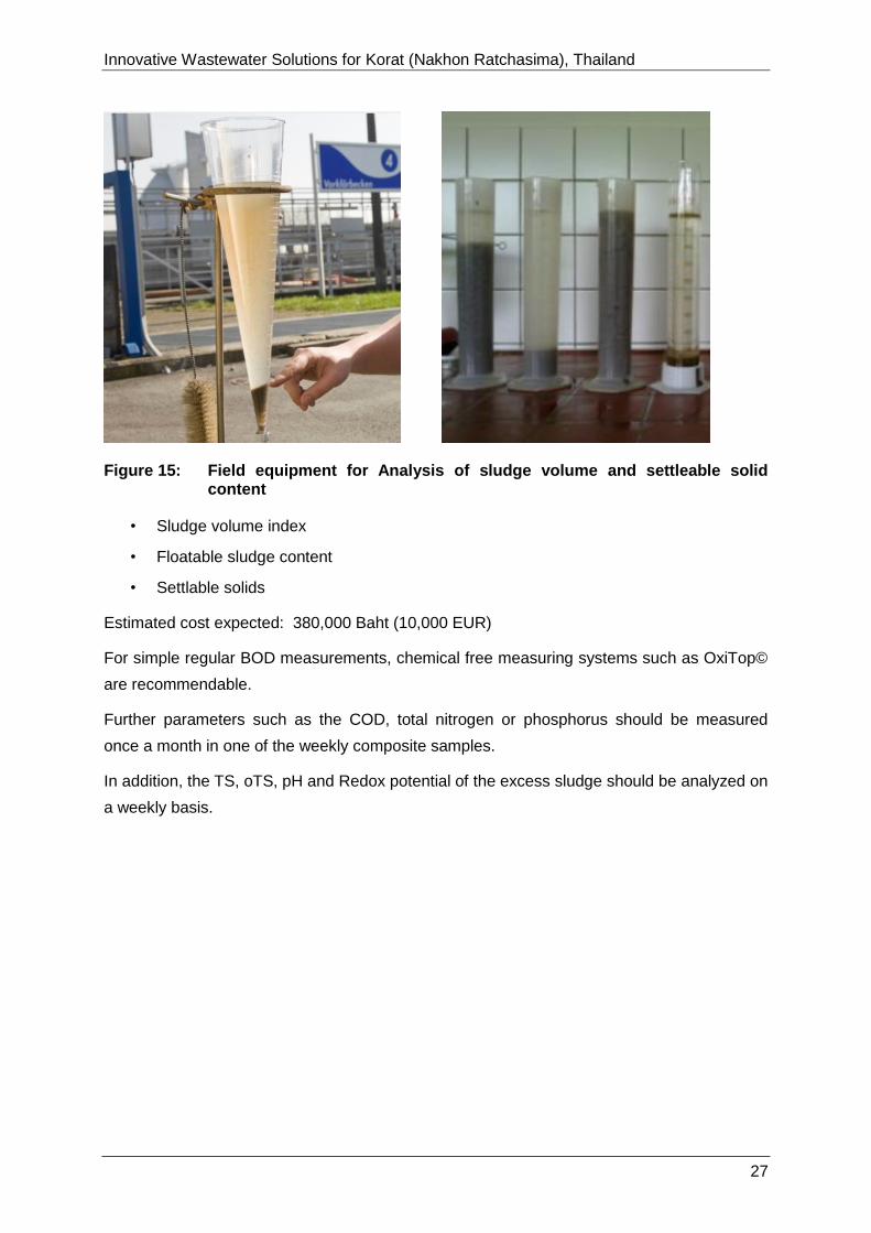
Figure 15: Field equipment for Analysis of sludge volume and settleable solid content
• Sludge volume index
• Floatable sludge content
• Settlable solids
Estimated cost expected: 380,000 Baht (10,000 EUR)
For simple regular BOD measurements, chemical free measuring systems such as OxiTop©
are recommendable.
Further parameters such as the COD, total nitrogen or phosphorus should be measured
once a month in one of the weekly composite samples.
In addition, the TS, oTS, pH and Redox potential of the excess sludge should be analyzed on
a weekly basis.
Innovative Wastewater Solutions for Korat (Nakhon Ratchasima), Thailand
170726-Report_on_Korat 28
2.4.3 Intermediate term measures
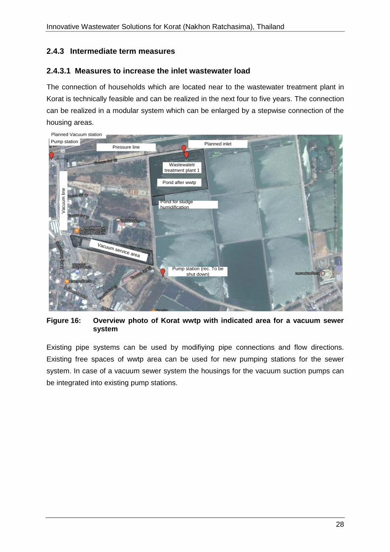
2.4.3.1 Measures to increase the inlet wastewater load
The connection of households which are located near to the wastewater treatment plant in
Korat is technically feasible and can be realized in the next four to five years. The connection
can be realized in a modular system which can be enlarged by a stepwise connection of the
housing areas.
Figure 16: Overview photo of Korat wwtp with indicated area for a vacuum sewer system
Existing pipe systems can be used by modifiying pipe connections and flow directions.
Existing free spaces of wwtp area can be used for new pumping stations for the sewer
system. In case of a vacuum sewer system the housings for the vacuum suction pumps can
be integrated into existing pump stations.
Pump station
Planned Vacuum station
Planned inlet
Wastewatetr
treatment plant 1
Pond after wwtp
Pond for sludge
humidification
Pump station (rec. To be
shut down)
Pressure line
Vacuum service area
Va
cu
um
lin
e

Innovative Wastewater Solutions for Korat (Nakhon Ratchasima), Thailand
170726-Report_on_Korat 29
2.4.4 Long-term measures
2.4.4.1 Sludge humification
As soon as the wastewater flow has been reversed and the AS plant is functional, the first
and second treatment ponds of the current system should be emptied. A part of the thereby
freed area should be converted into sludge humification beds (as shown in figure 17).
http://blumberg-engineers.com/de/10/klaerschlammvererdung
Figure 17: Photo of a sludge humification system (Left), area of the korat wwtp area needed for sludge humidification (right)
These flat beds will be filled continuously with the excess sludge. The planted reed plants
help dewatering and stabilizing the sludge over a period of 5-7 years. After that, the sludge
can be used as fertilizer in agriculture.
According to first estimations, an area of (only) 30,000 m2 is necessary for the humification
beds.
2.4.4.2 Active sludge management
Even with the flow direction reversed, the low content of degradable organic load in the
wastewater influent will continue to be a challenge for the AS system. An active sludge
management by the treatment plant staff, similar to the methods used at the Dindaeng Water
Environment Control Plant in Bangkok, should be implemented. This means that in case of
very low-loaded inflow, excess sludge from a storage tank should be pumped into the AS
basins in order to provide enough organic matter to keep the bacterial processes going.
This storage tank should have a volume of 250 m3, which is roughly equal to the daily excess
sludge production (thickened).

Innovative Wastewater Solutions for Korat (Nakhon Ratchasima), Thailand
170726-Report_on_Korat 30
2.4.4.3 Excess sludge treatment using an anaerobic sludge digestion
The excess sludge from the AS plant is a potential energy source and contains valuable
nutrients. Anaerobic sludge digestion is used worldwide as an effective treatment technology
which lowers significantly the bacterial activity while producing biogas at the same time.
Calculations show that up to 10 tSS of sludge could be produced at the Korat wastewater
treatment plant which can provide up to 2,000 Nm3/d of biogas. The digested sludge should
subsequently be dried in a solar drying plant for the use as agricultural fertilizer.
To implement this treatment chain, the following buildings are necessary:
A gravity thickener with a volume of about 780 m3 (height = 2,5 m, diameter = 20 m),
one or several sludge digesters with a total volume of about 8000 m3,
a sludge dewatering plant (e.g. belt filter press, screw presses etc.) and
a sludge drying plant
As the construction of sludge digesters demands detailed planning and a big investment from
the city or national budget, the implementation of an anaerobic sludge digestion is time
consuming. To be able to implement these measures as soon as possible, a short-term
solution for the sludge treatment is described below.

Innovative Wastewater Solutions for Korat (Nakhon Ratchasima), Thailand
170726-Report_on_Korat 31
3 FINDINGS of JUNE 2017 SURVEY on the MUNICIPAL WWTP KORAT
3.1 General remarks
Based on the recommendations of the Septemebr 2016 survey, presented on January 2017
to the Vice-mayor of the Korat municipality, the municipality has expressed their strong will to
improve the infrastructural works of the wwtp, including the misfunctioning scraper, sirrer and
aerator systems. The consultant send a second team to conduct a survey in June 2017 and
to formulate recommendations to support and guide the works intended by the Korat
municipality.
Overall, the wastewater treatment plant and the pumping stations seemed to be in good
condition. However, some issues were raised by the staff and were also observed by the
project team. The results of the check are listed in the Annexes. The things that should be
undertaken to make the wastewater treatment plant running are described in Annex 2 and 3:
Annex 1: Checklists of the pumping stations P1, P 2.1, P 2.2 and wwtp 1 – 3.
Annex 2: General To Do–List
Annex 3: Special recommendations for traveling bridges from Mr. Messmer AWT.
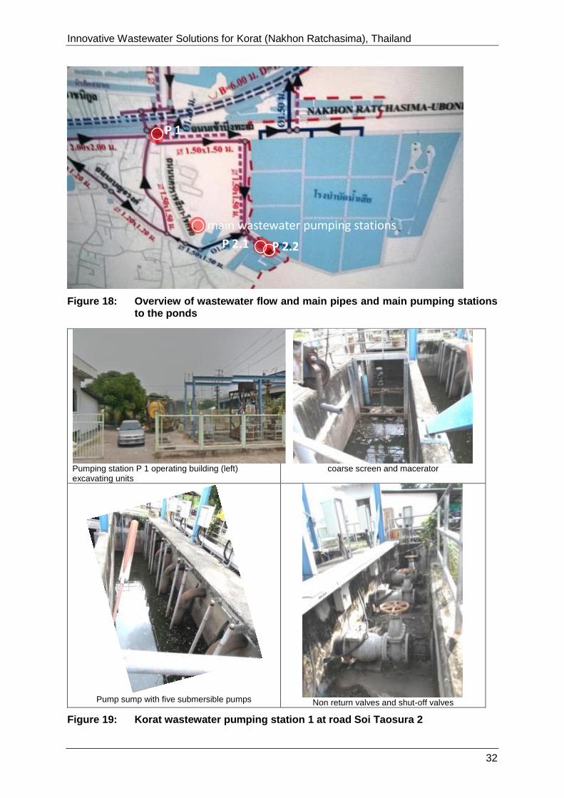
3.2 Findings in pumping stations P 1, P 2.1 and P2.2
Pumping Station P 1
Pumping station P 1 has a coarse screen, a macerator for the screenings and five
submersible pumps in the flow direction to the pump sump (see Figure 19).
Data, such as
1. yearly flow (m³/a),
2. maximum flow capacity (m³/h),
3. pump characteristics/charts, manufacturer and pump type
to know more about the design of the pumping station was not available during the visit.
The functionality of screen, macerator and the five pumps (currency uptake) could not be
tested.
The pumping direction is to the 1.5 m x 1.5 m channel to pumping station P 2.2 at the
wastewater pond (see Figure 18).
Innovative Wastewater Solutions for Korat (Nakhon Ratchasima), Thailand
170726-Report_on_Korat 32
Figure 18: Overview of wastewater flow and main pipes and main pumping stations to the ponds
Pumping station P 1 operating building (left) excavating units
coarse screen and macerator
Pump sump with five submersible pumps
Non return valves and shut-off valves
Figure 19: Korat wastewater pumping station 1 at road Soi Taosura 2
P 1
main wastewater pumping stations
P 2.2 P 2.1
Innovative Wastewater Solutions for Korat (Nakhon Ratchasima), Thailand
170726-Report_on_Korat 33
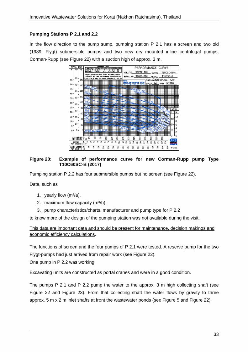
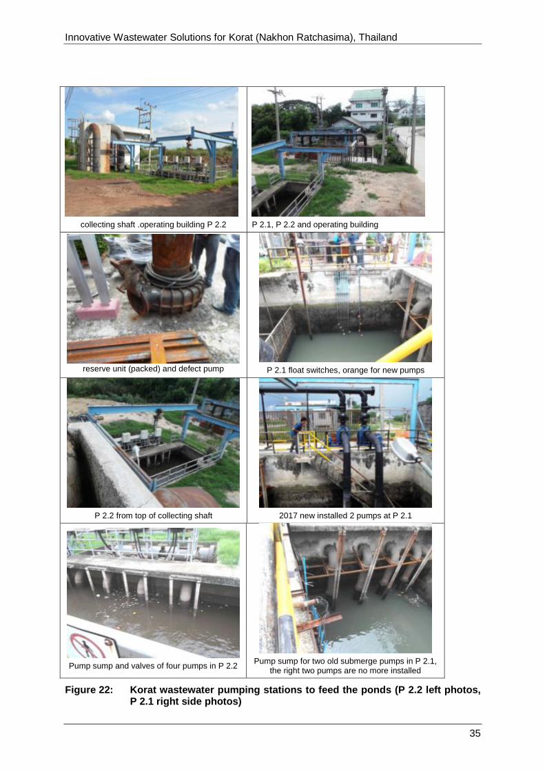
Pumping Stations P 2.1 and 2.2
In the flow direction to the pump sump, pumping station P 2.1 has a screen and two old
(1989, Flygt) submersible pumps and two new dry mounted inline centrifugal pumps,
Corman-Rupp (see Figure 22) with a suction high of approx. 3 m.
Figure 20: Example of performance curve for new Corman-Rupp pump Type T10C60SC-B (2017)
Pumping station P 2.2 has four submersible pumps but no screen (see Figure 22).
Data, such as
1. yearly flow (m³/a),
2. maximum flow capacity (m³/h),
3. pump characteristics/charts, manufacturer and pump type for P 2.2
to know more of the design of the pumping station was not available during the visit.
This data are important data and should be present for maintenance, decision makings and
economic efficiency calculations.
The functions of screen and the four pumps of P 2.1 were tested. A reserve pump for the two
Flygt-pumps had just arrived from repair work (see Figure 22).
One pump in P 2.2 was working.
Excavating units are constructed as portal cranes and were in a good condition.
The pumps P 2.1 and P 2.2 pump the water to the approx. 3 m high collecting shaft (see
Figure 22 and Figure 23). From that collecting shaft the water flows by gravity to three
approx. 5 m x 2 m inlet shafts at front the wastewater ponds (see Figure 5 and Figure 22).

Innovative Wastewater Solutions for Korat (Nakhon Ratchasima), Thailand
170726-Report_on_Korat 34
At the two pipes coming from the pumping stations 2.1 and 2.2 there are flow-measure
instruments (technical malfunction, see Figure 21).
Electrodes at pipe from P 2.1
Electrodes at pipe from P 2.1
Figure 21: Electrodes for flow-measurement at the pipes to the collecting shaft
Innovative Wastewater Solutions for Korat (Nakhon Ratchasima), Thailand
170726-Report_on_Korat 35
collecting shaft .operating building P 2.2
P 2.1, P 2.2 and operating building
reserve unit (packed) and defect pump
P 2.1 float switches, orange for new pumps
P 2.2 from top of collecting shaft
2017 new installed 2 pumps at P 2.1
Pump sump and valves of four pumps in P 2.2
Pump sump for two old submerge pumps in P 2.1, the right two pumps are no more installed
Figure 22: Korat wastewater pumping stations to feed the ponds (P 2.2 left photos, P 2.1 right side photos)

Innovative Wastewater Solutions for Korat (Nakhon Ratchasima), Thailand
170726-Report_on_Korat 36
The concrete on top and in the collecting shaft and the pipes in this area are heavily
corroded (see Figure 23). It could be renovated with Polyethylene plates or coatings.
Corrosion at handrails and concrete
Corrosion at pipe and concrete
Figure 23: Corrosion at pipes and concrete in the collection shaft from P 2.1 and P 2.2 (photos from top)
3.3 Findings in wwtp 1 – 3
As described in the preliminary studies, it is evident, that the organic load in the influent of
the activated sludge system is not sufficient to generate enough biomass for the system to
work properly.
Water quality parameter measured by FIW/KU-team, measured in October 2016
Inlet BOD: 23.5 – 25.9 mg/l
Inlet COD: 46.9 – 54.3 mg/l
Inlet TKN: 8.1 – 11.5 mg/l.
This is due to the degradation processes in the upstream treatment ponds and especially
due to the septic tanks in use on most housing and commercial plots in the city, required by
the national regulation for septic tanks.
To solve the problem of the low inlet loads,
the flow direction could be changed (see chapter 3.4.5) (this measure will avid the
degradation in the ponds) and
there could be generated higher concentrated wastewater in the inflow by adding
higher wastewater, such as wastewater that is directly sucked by a vacuum system
from households (by-passing the septic tanks and not using a septic tank before
entering the wwtp.
The construction of the three plants (wwtp 1 – 3) is identical and shown in Figure 24
(aeration basin) and Figure 25 (sedimentation basin).
Each plant consists of one large aeration basin that is aerated by four aerators and 528
membrane diffusors at the ground of the basin. The inflow from the ponds flows by gravity

Innovative Wastewater Solutions for Korat (Nakhon Ratchasima), Thailand
170726-Report_on_Korat 37
(water-level difference between aeration basin and ponds) to the non-aerated zone of the
basin, just after the inflow of the recycled sludge.
The aerated zone should have an oxygen concentration of 1.5 mg/l; sludge in the aeration
basin should grow to 3-4 g/m³. 3 of the 4 installed stirrers have to operate continuously.
The traveling bridges and two of the three recycle-sludge pumps should work for 24 h/d
continuously. Surplus sludge should be pumped away, if the sludge concentration in the
aeration basin is higher than 4 mg/l. In a first phase, regarding the low measured load, it will
be sufficient to operate only two of the three plants.
Figure 24: Principle aeration basin, recycle sludge pumps, surplus sludge pumps
Figure 25: Principle sedimentation basin with traveling bridges
4 Stirrer/mixer 4 Aerators 3 Recycle sludge
pumps
Inflow from pond
48 x 11 = 528 Membranes Outlet to sedimentation
basin
traveling bridge
Effluent, cleaned wastewater
From aeration basin
3 Recycle sludge pumps
2 Surplus sludge pumps
Innovative Wastewater Solutions for Korat (Nakhon Ratchasima), Thailand
170726-Report_on_Korat 38
3.3.1 Findings at wwtp 1
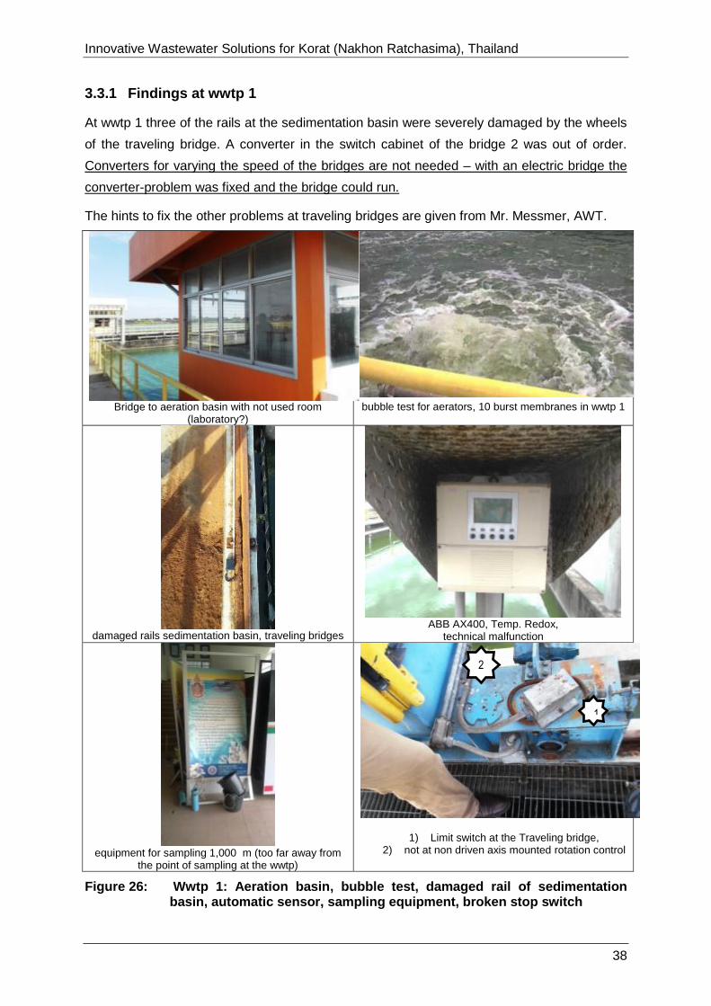
At wwtp 1 three of the rails at the sedimentation basin were severely damaged by the wheels
of the traveling bridge. A converter in the switch cabinet of the bridge 2 was out of order.
Converters for varying the speed of the bridges are not needed – with an electric bridge the
converter-problem was fixed and the bridge could run.
The hints to fix the other problems at traveling bridges are given from Mr. Messmer, AWT.
Bridge to aeration basin with not used room (laboratory?)
bubble test for aerators, 10 burst membranes in wwtp 1
damaged rails sedimentation basin, traveling bridges
ABB AX400, Temp. Redox,
technical malfunction
equipment for sampling 1,000 m (too far away from
the point of sampling at the wwtp)
1) Limit switch at the Traveling bridge,
2) not at non driven axis mounted rotation control
Figure 26: Wwtp 1: Aeration basin, bubble test, damaged rail of sedimentation basin, automatic sensor, sampling equipment, broken stop switch
2
)
1
Innovative Wastewater Solutions for Korat (Nakhon Ratchasima), Thailand
170726-Report_on_Korat 39
Aeration basin
The bubble test in the aeration basin showed approx. 10 damaged aeration membranes (see
Figure 26). These membranes have to be changed by an industrial diver. The basin cannot
be completely emptied, because the walls of the basin are not designed for more than 1 m
difference of water level in and out of the basin.
Control of wastewater temperature, oxygen (also recommended: Redox-potential, see
chapter 3.4.2) is needed for economic operation. For safety of the workers there should be a
life-belt at the railing of the aerated basin and the lights should operate correctly (approx. 10
lights of each wwtp are damaged).
The long distance to the laboratory leads to false analytics because the sample react
chemically in the hot climate. It is easier to analyze the samples just after taking them in the
rooms that are near each bridge of the aeration basin. The data will be more accurately.
Another technical option is the installation of automatic measurements of oxygen contents
and nitrate concentrations at two points inside of each aeration basin.
The switch cabinets must be cleaned. The evidence of breeding pigeons inside the service
room and of geckos inside of the cabinets should be not tolerated.

Innovative Wastewater Solutions for Korat (Nakhon Ratchasima), Thailand
170726-Report_on_Korat 40
3.3.2 Findings at wwtp 2
The result of check of wwtp 2 is better than the wwtp 1. The bubble test showed no damaged
membranes. All pumps worked well – a little grease and oil was needed for the gear-boxes of
the motors and the wheel bearings (see Figure 27).
Aeration basin
bubble test for aerators without defects
recycle sludge pumps
surplus sludge pumps
Manual grease gun for wheel bearings sedimentation basin 1 with traveling bridge
Figure 27: Wwtp 2: Aeration basin, recycle sludge pumps, surplus sludge pumps, operstor with grease gun, sedimentation basin with traveling bridges
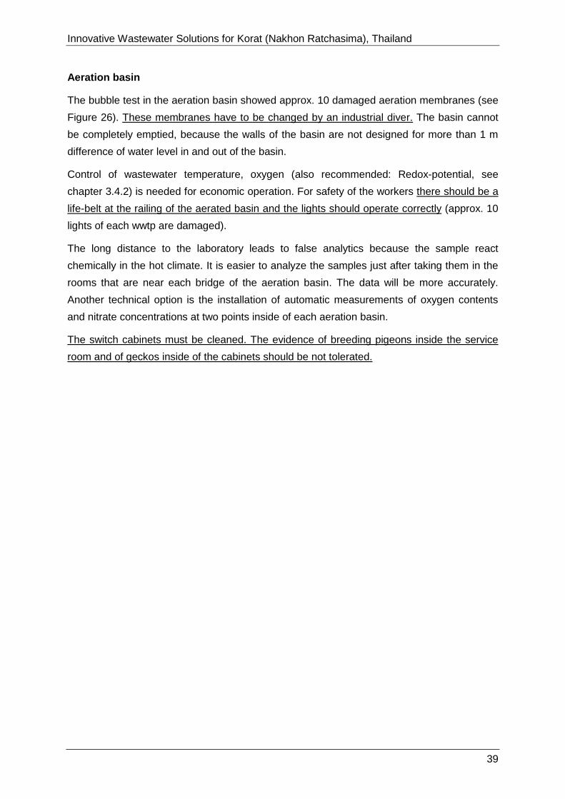
After changing one motor for the traveling bridge from wwtp 1 to wwtp 2 both traveling
bridges of wwtp worked the full way (50 m) up and down the sedimentation basin under
supervision. The sludge of the sedimentation basins was pumped to the aeration basin and
in the short-time test seemed to work quite well (see Figure 28).
Innovative Wastewater Solutions for Korat (Nakhon Ratchasima), Thailand
170726-Report_on_Korat 41
20 mg/l sludge
Sludge in aeration basin wwtp 2 after one day operation
Figure 28: 20 ml/l Biomass in the aeration basin after one day operation of wwtp 2
The measurement of currency of the aerators show differences (aerator 1 has the highest
currency uptake of the 4 aerators / and pump 2 has a higher currency than pump 1 and 3.)
This observation gives the hint to save energy by re-switching the pumps as follows:using
Pump 1 and 3 or aerator 2 instead of aerator 1 can save up to 10 % of electric energy.
Table 1 Measured electric currency for aerators and recycle pumps (as a hint for maintenance)
Aerator 1 48 Amp Pump 1 36 Amp
Aerator 2 42 Amp Pump 2 42 Amp
Aerator 3 46 Amp Pump 3 35 Amp
Aerator 4 45 Amp
Safety and working conditions can be improved, for fixing of problems with the traveling
bridges see Annex 3.
The switch cabinets must be cleaned.

Innovative Wastewater Solutions for Korat (Nakhon Ratchasima), Thailand
170726-Report_on_Korat 42
3.3.3 Findings at wwtp 3
The condition of wwtp 3 was checked, although knowing that the plant was never in
operation, in order to find hints how to use parts of wwtp for the support of the foreseen
operations of wwtp1 and or wwtp 2.
The main switch of the electric power supply of wwtp 3 was out of order. The main cable to
this plant was disconnected. Operation of the stirrers, aerators, pumps and traveling bridges
could not be checked. The rails of the traveling bridges at wwtp 3 were in a good condition.
All the wheels of the traveling bridge and one grating were missing (used in wwtp 1 + 2).
Main switch, does not operate, no power supply to wwtp 3
Approx. 10 diffuser luminaires are broken or lost
in each wwtp
Door aerator building, key is missing
All 4 Rails wwtp3 are in good condition (not used),
one grating is missing
aeration basin excavating unit for stirrers
sedimentation basin 1+2with traveling bridges
without wheels
Figure 29: Wwtp 3: Main inlet power switch, sedimentation basin with traveling bridges, door of machinary house, broken rails, broken cable lift ffor of stirrer, damaged rail

Innovative Wastewater Solutions for Korat (Nakhon Ratchasima), Thailand
170726-Report_on_Korat 43
The four installed stirrers could not be lifted because the excavating unit was damaged.
The door of the aerator room must be repaired – a key for this room was missing.
The switch cabinets must be cleaned because the dirt on the plates can cause a short
circuit.

Innovative Wastewater Solutions for Korat (Nakhon Ratchasima), Thailand
170726-Report_on_Korat 44
3.4 RECOMMENDATIONS to improve the Wastewater Treatment Plant
3.4.1 Preamble and clarifications
It is important to note that the underlying calculations are based on the full capacity of the
existing activated sludge plant. However, it can be supposed that the actual inflow load is
currently below the plant’s capacity. Therefore, a step by step approach is highly
recommended. With the data and experience from the first steps i.e. the reactivation of the
first two AS plants ( wwtp 1, wwtp 2) and the improved analysis plan, the planning of the
long-term measures should be adjusted accordingly. Furthermore, measures to increase the
inflow load should be implemented to increase the plant’s efficiency and reduce the
environmental impact of non-treated wastewater in the city. An optimal use of the wastewater
treatment plant’s capacity should also play an important role in the recommended integrated
urban drainage planning.
3.4.2 Improvement of the measuring and analysis system of the wwtp
The lack of reliable long term wastewater data from the treatment plant influent and effluent
hamper the planning of sensible modifications. To further improve the assumptions made for
the wastewater load calculations and enable the plant’s staff and planners to react in case of
changing influent, a regular sampling plan should be implemented. This is also necessary to
enable an active sludge management.
The key parameters BOD, TS, SS, pH and Ammonium and nitrate should be analyzed at
least on a weekly basis at varying weekdays and times of the day. The samples should be
composite samples mixed out of at least five catch samples taken in a timeframe of two
hours.
For simple regular BOD measurements, chemical free measuring systems such as OxiTop©
are recommendable.
Further parameters such as the COD, total nitrogen or phosphorus should be measured
once a month in one of the weekly composite samples.
In addition, the TS, oTS, pH and Redox potential of the excess sludge should be analyzed on
a weekly basis.
To analyze the process of wastewater treatment better and to save energy the wwtp 1-3 the
plants should have continuous measure equipment for the following parameters
1. Flow (m³/h, m³/a), installed at the outlet of the clarifier basins
2. Oxygen (mg/l, g/m³), installed at the end of the aerated zone of the aeration basins
3. Nitrate (mg/l, g/m³), installed at the end of the not aerated zone of the aeration basins
4. Phosphorus, installed at the outlet of the last treatment unit (now outlet clarifier basin,
later on when changed flow direction outlet of ponds)

Innovative Wastewater Solutions for Korat (Nakhon Ratchasima), Thailand
170726-Report_on_Korat 45
For Nitrate and Phosphorus (3. and 4.), it is a matter of cost efficiency to measure these
parameters twice a day for three plants in the laboratory or online with automatic data-
sampling.
Information of distribution companies and types of measuring instruments
Examples of distribution companies and types of measure – equipment used for working in
wastewater treatment plants are given here:
Temperature, Nitrate-N (NO3-N), Phosphate (PO4-P) Flow,
Oxygen – with self-cleaning electrodes:
1. HACH LANGE GmbH, Willstätterstraße 11
40549 Düsseldorf, Germany
Phone: +49 / (0)211 / 5288-0 Fax: +49 / (0)211 / 5288-143
Mail: [email protected], Internet: http://hlzdata.com/e/default.htm
http://www.chemeurope.com/en/companies/303/hach-lange-gmbh.html
Flow, Temperature, Phosphate (PO4-P), Nitrate-N, Oxygen:
2. ABB, ABB Asea Brown Boveri Ltd
CEO: Ulrich Spiesshofer
Address: Affolternstrasse 44, 8050 Zurich, Switzerland
Phone: +41 43 317 7111 Fax: +41 43 317 4420
The ABB Contact Directory (http://www.abb.com/contacts/) helps you find local sales
and services contacts for ABB products in your country.
Temperature, Nitrate-N (NO3-N), Phosphate (PO4-P) Flow:
3. Xylem Analytics Germany Sales GmbH & Co. KG, WTW, Dr.-Karl-Slevogt-
Straße 1
82362 Weilheim, Germany
Phone: +49 881 183-0 Fax: +49 881 183-420
E-Mail: [email protected],
Web: https://www.wtw.com/en/contact/wtw-head-office.html
Innovative Wastewater Solutions for Korat (Nakhon Ratchasima), Thailand
170726-Report_on_Korat 46
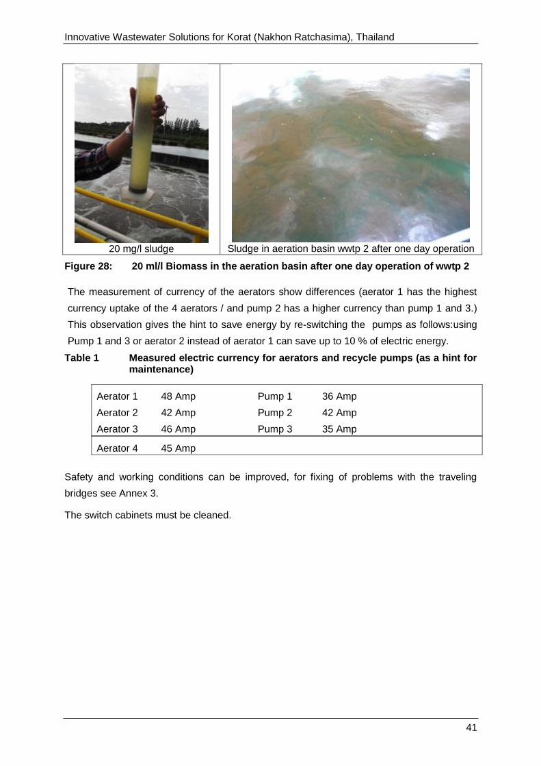
The electrode – types are looking like shown in Figure 30. Controllers and interfaces for
control and regulate are offered for serving up to 20 sensors and have a data-store on
demand.
Figure 30: Wastewater Measurement electrode – types
3.4.3 Improvement of safety and working conditions
For the safety of the workers there should be a life belt mounted at the middle of the aeration
basin, for its not possible to swim in aerated water.
The lot of broken lights should be procured and mounted and improved cost-effectiveness of
LED lights should be checked.
Working conditions could be improved by pneumatic grease presses, pressure water
cleaners and industrial vacuum cleaner. The daily needed equipment (Oil, grease, working
tools, quick-tests measurement equipment like water sampler, beaker, Imhoff hoppers,
portable measurement for pH-, oxygen, …) should be in the rooms at the wwtps.
3.4.4 Improvement of the budget system
For a faster reaction to manage regular maintenance and repair of equipment of the
wwtp 1-3 and to conduct the monitoring and analysis the staff responsible for the operation
and maintenance of the wwtp should have their own budget. The allocation can be done on a
yearly basis.
3.4.5 Reversal of wastewater flow
To raise the amount of degradable organic matter in the activated sludge basins, the
wastewater should be directly pumped into the AS plant without prior treatment in the pond
system, as seen in Figure 31.

Innovative Wastewater Solutions for Korat (Nakhon Ratchasima), Thailand
170726-Report_on_Korat 47
Figure 31: Korat Wastewater Treatment Plant with reversed wastewater flow
Detailed calculation on the basis of the DWA A 131 (2016) in combination with the DWA-
Topics T4/2016 (Design of wastewater treatment plant in warm and cold climate zones) show
that the AS plant is capable of treating up to 100,000 m³/d wastewater and roughly 18 t/d of
BOD load.
To reverse the wastewater flow, the pressure pipe, coming from the pumping station P 1
(Figure 5) and leading towards the pumping station P 2.1 of the treatment plant, needs to be
redirected towards the AS plant. It has to be determined whether a new inflow pumping
station is necessary or not. If the pumps at station number P1 have enough power to pump
the wastewater directly into the new to build distributor to the AS basins, only a new flow
separation unit (distributor like shown in Figure 32) needs to be installed. (Fig.32 shows a
distributor system for a distribution starting from the middle of the wwtp system.)
Figure 32: Example of a new distributor to Korat Wastewater Treatment Plant
Innovative Wastewater Solutions for Korat (Nakhon Ratchasima), Thailand
170726-Report_on_Korat 48
3.4.6 Recommended action plan to restart the main wastewater treatment
plant in Korat
The first step in reactivating the wwtp 1 and wwtp 2 should be the repair of the travelling
bridges over the clarifier basins of the AS system. To prevent the bridges from failing again it
should be modified like shown in the recommendations of Mr. Messmer (see Annex 3).
The second step is to get all things done due to the ToDo-List in Annex 2. The effects of this
reparations and addition equipment should be checked by experts and
The third step would be a planning for
the new distribution building for a hydraulic distribution of Wastewater from P 1 and
P 2.2 to wwtp 1 - (2) 3
the connecting pipes from pumping stations and to the aeration basins of wwtp 1 - (2) 3
Effluent from P1 and P 2.2 first into new distributor, from there to wwtp 1- 3, from there
to the ponds and out of the ponds to the outlet pipes of wwtp 1 - (2) 3.
In the long term, the construction of a combined, aerated sand- and grease trap basin prior
to the AS system is recommendable in order to keep sand from sedimenting in the AS
basins. The collected sand can be used for example in road construction, for land-scaping
and the retained grease can later be cofermented in the digestion tank (or the surplus sludge
basin), which will lead to a higher biogas yield if treated in a digestion tank. However, the
construction will be costly because of the AS systems’ locations in the last treatment ponds,
which makes a more complicated pipe layout necessary to install an upstream basin.
3.4.7 Active sludge management
Even with the flow direction reversed, the low content of degradable organic load in the
wastewater influent will continue to be a challenge for the continuous operation of the AS
system.
A sludge management system has to eb installed to guarantee enough active bacteria mass
(Activated sludge) even in cases of emergencies. An active sludge management by the
treatment plant staff, similar to the methods used at the Dindaeng Water Environment
Control Plant in Bangkok, should be implemented. This means that in case of very low-
loaded inflow, excess sludge from a storage tank should be pumped into the AS basins in
order to provide enough organic matter to keep the bacterial processes going.
This storage tank should have a volume of 250 m3, which is roughly equal to the daily excess
sludge production (thickened).

Innovative Wastewater Solutions for Korat (Nakhon Ratchasima), Thailand
170726-Report_on_Korat 49
3.4.8 Options for a sustainable operation of the wastewater treatment plant
operation
After setting into operation of the waste water treatment process at the wastewater treatment
plant in Korat there should be taken some measures to guarantee a long-lasting operation.
Among these options are the improvement of the technical equipment, the knowledge of the
operational staff, the replacement of less effective instruments or machines, improvement of
the knowledge of new technical developments.

Innovative Wastewater Solutions for Korat (Nakhon Ratchasima), Thailand
170726-Report_on_Korat 50
3.5 Annotation for the repair of the travelling bridges of the rectangular tanks
of wwtp 1 and wwtp 2
(written by Mr. Messmer, awt Umwelttechnik Eisleben, Germany)
The travelling bridges need one guiding side with two wheels with flanges moving on one rail.
The guiding side will have contact to the top and to the sides of the rail head.
The other side moves without guiding flanges only on the top of the rail head from the
second rail.
Figure 33: Hand drawing of the guding and rollng side of a traveling bridge

Innovative Wastewater Solutions for Korat (Nakhon Ratchasima), Thailand
170726-Report_on_Korat 51
These are the non-guiding wheels.
The guiding wheel should have a 5 mm wider running surface than the width of the rail head
is.
The guiding wheel must be align together. The non-guiding wheels must align together and
must be parallel to the alignment of the guiding wheels.
The guiding and non-guiding wheels must be fixed on the axles. There is no movement in
direction of the axles allowed. This can be done by spacer sleeves to the bearings which are
connected to the driving chassis.
The non-guiding wheels must be wide enough to handle the wide-tolerances of one rail to the
other rail.
The tolerance in the wide of one rail to the other rail is for tank wides below 15 m max
allowed to +- 5 mm.
The tolerance in height is allowed to +-2mm for a 2m section. For the complete railway are +-
5 mm allowed.
Rail joint must have a smooth top level without a noticeable height difference. Rail joints
must be connected by rail joiners or must be welded to fix the height from one side to the
other side while handling the wheel-loads.
The drive motor can be installed in the middle of the bridge connected with transmissions to
the driven wheels or every driven wheel can be directly connected with a drive motor.
One non-driven wheel from a travelling bridge must be equipped with a sensor and a sensor-
plate to control the turning of the non-driven wheel if the drive motor is in operation. If the
drive motor is operating and the sensor for monitoring the non-driven wheel shows 5sec no
turning, the drive motor must immediately stop to prevent the travelling bridge and the
wheels from damages and to prevent the bridge to come out of the railway.
On each end of the rails there are sensor-plates or cushions to switch one of the end-position
sensors. It’s not necessary that both switches stop the bridge. It is allowed that one side of
the bridge stops when the other side is up to …100 mm in front of the end position. This can
vary from travel to travel depending on tolerances in the rails and in different sludge and
wind-loads to the bridge.
Further details are given in more detailed hand drawings fo the rail and wheels system in the
annex.

Innovative Wastewater Solutions for Korat (Nakhon Ratchasima), Thailand
170726-Report_on_Korat 52
3.6 Annotation to the change of flow direction and the new distributor to feed
wwtp 1 / 2
(written by Bernhard Wöffen, FiW)
Remark: Assuming the repair of the wastewater treatment plant wwtp 1 and wwtp 2, the
advisory team has agreed on the fact that the wastewater should first be treated by the wwtp
and not by the pond system. The pond system will be foreseen as maturation of the treated
wastewater effluent of the wwtp. The chapter 3 “Annotation to the change of flow direction
and the new distributor to feed wwtp 1 / 2” contains calculations and technical hints, that
describe the necessary steps, followed by a cost estimation.
The infrastructural works contain various tasks: A new distributor, new influent pipes have to
be build, some openings for the new effluents and close the old effluents are necessary to
change the flow direction.
The temporal order of the changing of the flow direction is described as follows (see Figure
34: Chronological order of changing flow direction34).
1. Construction of the distributor on the existing pipeline from the pumping station P1 to
the pumping station P 2.01 with the feed lines to the aeration basin of wwtp 1 + 2.
2. Preparation of the new settling tank effluents: drain openings 0.9mx0.9 m in the
effluent channels opposite the current drain.
3. Production of the new pond flows through a shaft on the existing drainage line to the
secondary sedimentation tank and new upstream drainage pipes (UK 1 m under
current pond water level).
1. 1.a. Commissioning of the distributor by opening the pipeline and installing a slide
valve on the side of the pipeline to the PW 2.02 (PW 2.02 goes out of operation)
4. Construction of the pumping line from PW 2.01 to the new distributer (use of the
former pipeline PW1 to P 2.02 along the pond in the counter-flow direction)
4. 4.a Commissioning of the new (old) pump line to the new distributor bay (pressure
line connection PW, opening of the built-in shut-off at the distributor)
5. Closure of the "old" drains of the settling tank.
6. Close "old" effluents of the aeration basin.
7. Emptying the no longer required ponds and closing the existing pond passages.
8. Reserved areas for sludge treatment.

Innovative Wastewater Solutions for Korat (Nakhon Ratchasima), Thailand
170726-Report_on_Korat 53
Figure 34: Chronological order of changing flow direction
The technical information of the existing pipes (diameters, depth and materials) and the
capacity of the pumping stations are not sufficient to construct the new distributor exactly.
A formal outline of the distributor is given in Figure 35: Formal outline of the distributor
for feed of wwtp 1 + 2.Without the house for the vacuum system the building is 9.90 m x 4.00
m in length and width. Depending on the depth of the pipe from pumping station 1 to
pumping station 2.02 at the edge of the ponds the depth of the distributor should be 3.50 m
(see Figure 36 and
The hydraulic losses for the needed pipes are calculated in Table 2 Hydraulic losses
and needed length of the pipes from in the distributor
. These losses are calculated on a basis of 2,500 m³/h for the pipes to wwtp 1 / 2. The
estimation of the flow is based on 100,000 m³/d capacity of the plants (2 · 2,500 m³/h · 24 h/d
= 120,000 m³/d).
Table 2 Hydraulic losses and needed length of the pipes from in the distributor
The overflow height over the spillway of 4.50 m length is 0.30 m for 5,000 m³/h overflow and
0.19 m for the regular overflow of 2,500 m³/h.
from to di Länge L 0,02*L/Di v v2/2g hv
Distributor wwtp1 1,000 mm 145 m 2.90 0.88 m/s 0.040 m 0.116 m
wwtp2 1,000 mm 371 m 7.42 0.88 m/s 0.040 m 0.296 m
emergency overflow pond 1,200 mm 10 m 0.17 1.23 m/s 0.077 m 0.013 m

Innovative Wastewater Solutions for Korat (Nakhon Ratchasima), Thailand
170726-Report_on_Korat 54
For the emergency overflow to the 1,200 mm pipe there is an overflow high of 0.34 m
calculated.
The most commonly used baffles are fixed baffles per DIN 19558 with a clearance between
baffle and crest of 2 times the overflow head (2 x 0.19 = about 0.4 m, see Figure 35:
Formal outline of the distributor for feed of wwtp 1 + 2).

Innovative Wastewater Solutions for Korat (Nakhon Ratchasima), Thailand
170726-Report_on_Korat 55
Figure 35: Formal outline of the distributor for feed of wwtp 1 + 2
Pipe from P1, estimated DN 1.200, estimated depht 2,50 m
House for the
Vacuum system
effluent
Vakuum
system
Layout of the distributor
DN 1000 Pipe to wwtp 2, 371 m
DN 1000 Pipe to wwtp 1, 145 m
emergency overflowDN 1200, to pond, 10 m
Estimated DN 1200 Pipe Valve for shut of to build connection to P 2.01
4,5 m
kn
ife
ga
te v
alv
es
top
of
sp
illw
ay:
ma
x.
top
wa
ter
a
era
tio
n
ba
sin
+ lo
sse
s p
ipe
, …
+
0,3 m
0,3 m
4,5 m
3,0 m
0,3 m
12
,90
m
0,3 m0,3 m 0,3 m1,3 m
4,0 m
1,4 m 0,4
0,80
m s
cum
baf
fle
AA
B
B
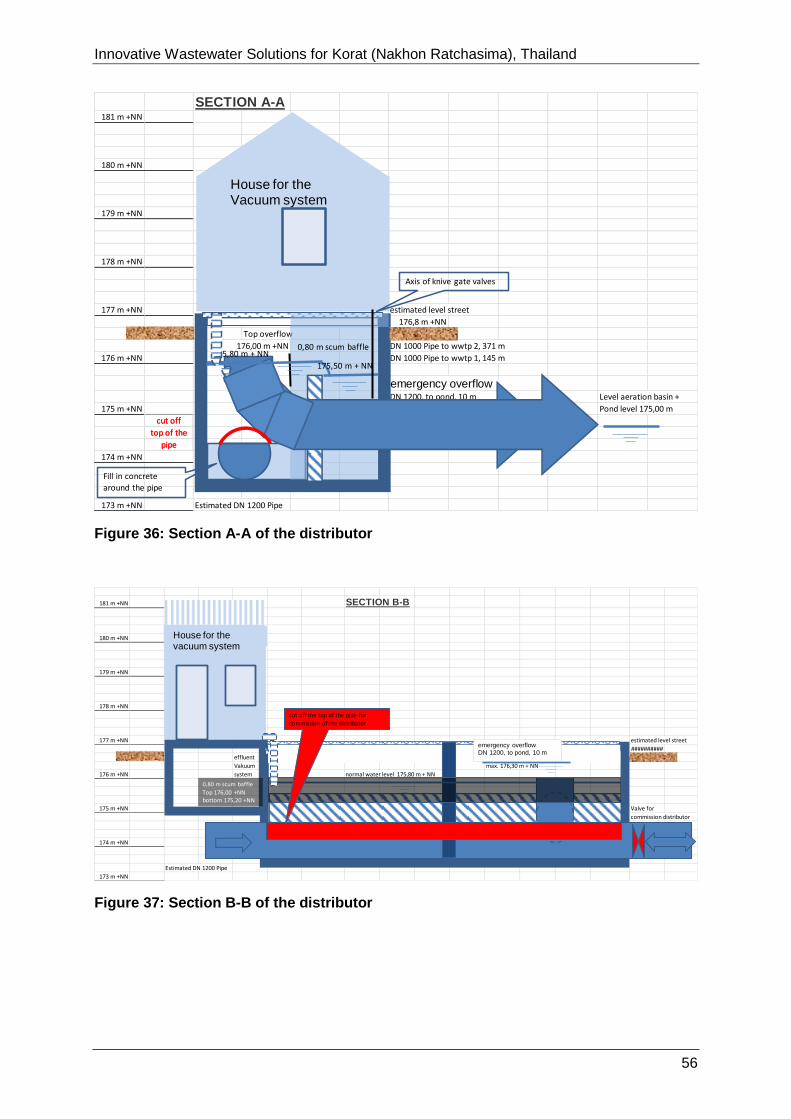
Innovative Wastewater Solutions for Korat (Nakhon Ratchasima), Thailand
170726-Report_on_Korat 56
Figure 36: Section A-A of the distributor
Figure 37: Section B-B of the distributor
SECTION A-A181 m +NN
180 m +NN
179 m +NN
178 m +NN
177 m +NN estimated level street
176,8 m +NN
Top overflow
176,00 m +NN DN 1000 Pipe to wwtp 2, 371 m
176 m +NN DN 1000 Pipe to wwtp 1, 145 m
emergency overflowDN 1200, to pond, 10 m Level aeration basin +
175 m +NN Pond level 175,00 m
cut off
top of the
pipe
174 m +NN
173 m +NN Estimated DN 1200 Pipe
House for the Vacuum system
Axis of knive gate valves
0,80 m scum baffle
175,50 m + NN
175,80 m + NN
cut off
top of the
pipe
Fill in concrete
around the pipe
181 m +NN SECTION B-B
180 m +NN
179 m +NN
178 m +NN
177 m +NN estimated level street
##########
effluent
Vakuum max. 176,30 m + NN
176 m +NN system normal water level 175,80 m + NN
175 m +NN Valve for
commission distributor
174 m +NN
Estimated DN 1200 Pipe
173 m +NN
emergency overflowDN 1200, to pond, 10 m
0,80 m scum baffle
Top 176,00 +NNbottom 175,20 +NN
cut off the top of the pipe for
commission of the distributor
House for the vacuum system
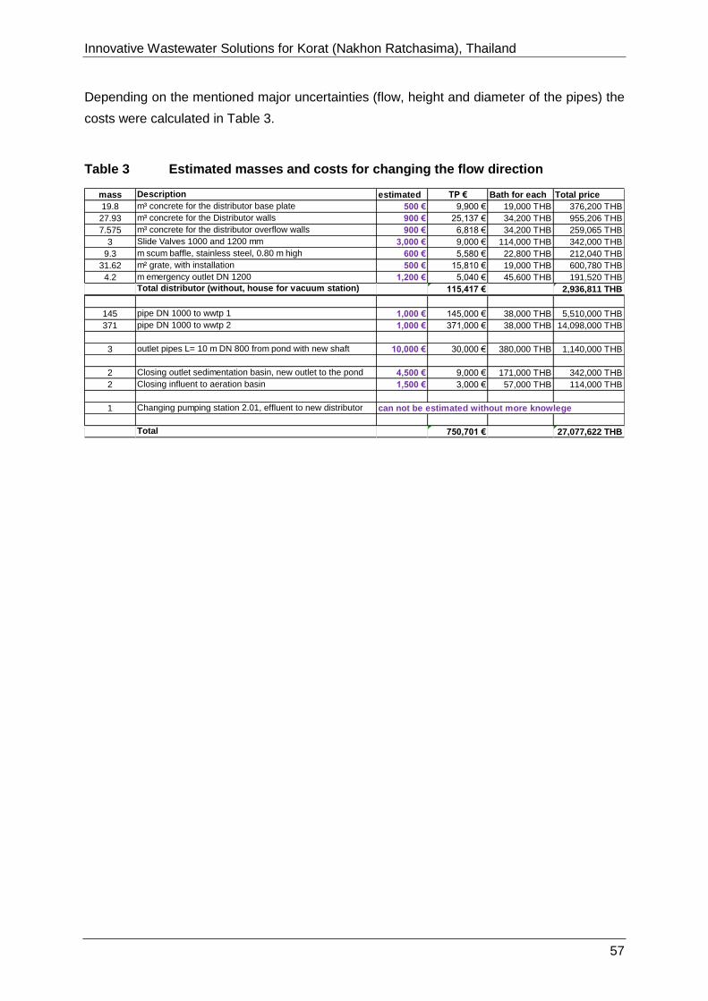
Innovative Wastewater Solutions for Korat (Nakhon Ratchasima), Thailand
170726-Report_on_Korat 57
Depending on the mentioned major uncertainties (flow, height and diameter of the pipes) the
costs were calculated in Table 3.
Table 3 Estimated masses and costs for changing the flow direction
mass Description estimated TP € Bath for each Total price
19.8 m³ concrete for the distributor base plate 500 € 9,900 € 19,000 THB 376,200 THB
27.93 m³ concrete for the Distributor walls 900 € 25,137 € 34,200 THB 955,206 THB
7.575 m³ concrete for the distributor overflow walls 900 € 6,818 € 34,200 THB 259,065 THB
3 Slide Valves 1000 and 1200 mm 3,000 € 9,000 € 114,000 THB 342,000 THB
9.3 m scum baffle, stainless steel, 0.80 m high 600 € 5,580 € 22,800 THB 212,040 THB
31.62 m² grate, with installation 500 € 15,810 € 19,000 THB 600,780 THB
4.2 m emergency outlet DN 1200 1,200 € 5,040 € 45,600 THB 191,520 THB
Total distributor (without, house for vacuum station) 115,417 € 2,936,811 THB
145 pipe DN 1000 to wwtp 1 1,000 € 145,000 € 38,000 THB 5,510,000 THB
371 pipe DN 1000 to wwtp 2 1,000 € 371,000 € 38,000 THB 14,098,000 THB
3 outlet pipes L= 10 m DN 800 from pond with new shaft 10,000 € 30,000 € 380,000 THB 1,140,000 THB
2 Closing outlet sedimentation basin, new outlet to the pond 4,500 € 9,000 € 171,000 THB 342,000 THB
2 Closing influent to aeration basin 1,500 € 3,000 € 57,000 THB 114,000 THB
1 Changing pumping station 2.01, effluent to new distributor can not be estimated without more knowlege
Total 750,701 € 27,077,622 THB
Innovative Wastewater Solutions for Korat (Nakhon Ratchasima), Thailand
170726-Report_on_Korat 58
3.7 Annotation to the use of the pond area for the installation of a Photo
voltaic plant
(calculated by the Mr Mihael Ketov, Institute for Electrical Plants and Energy Management,
RWTH Aachen University (IAEW))
Remark: In case of a successful reactivation and renewal of the wastewater treatment and
sewage sludge management in Korat there will be decisive change of the existing land used
for the main waste water treatment plant in Korat. About half of the pond area will not be
used for the waste water treatment process. There will be big potential for new land use by
the municipality of Korat. Options already mentioned are the installation of a solar and wind
park for the generation of electricity.
Calculation of the possibilities of using PV and wind turbines on the land of 270,300
m² of the treatment plant area.
Use of wind turbines
Regarding the close distance to the military airport in Korat and the housing areas near to the
wastewater treatment plant, it is very unlikely that a permit for the installation of wind mills
will be issued. The height of suitable wind mills will be higher than150 m.There will be
shadow effects, noise emissions, and adverse effects on the air traffic.
Regarding the available wind velocities at that locations, the operation of wind mills will be
positively assessed, but due to the other local limitiations no further evaluations were done.
Calculation of the possibilities of using Photo voltaic plant
Assumptions:
Available land area of 270,300 m² (not used pond area).
Only upfront investment without maintenance costs. Power grid extension costs not
considered.
Panels after investment period with no value.
Constant over time: full load hours, efficiency, solar radiation, feed-in tariff, exchange
rate and cost of capital.

Innovative Wastewater Solutions for Korat (Nakhon Ratchasima), Thailand
170726-Report_on_Korat 59
Table 4 Technical input and output data for the PV plant on the wwtp area in Korat
Parameter Value Unit source
Input data (Technical)
average full load
hours
1350 h/a http://re.jrc.ec.europa.eu/pvgis/apps4/
pvest.php?lang=en&map=africa
usable net area 270 300 m²
efficiency 14 % https://en.wikipedia.org/wiki/ Solar_cell_efficiency
average solar
radiation at standard
conditions
1 kW/m²
Output data (Technical)
total installed
capacity
37.84 MWp calculated
average feed-in 51 086.7 MWh/a calculated
Parameter Value Unit source
Input data (Financial)
feed-in tariff 4.12 THB/kWh Projects phase 2, source: http://www.thai-german-
cooperation.info/admin/ uploads/publication/
384bf513d3c90d94c 609e 739be270b3den.pdf
exchange rate =1/38.58 EUR/TBH
total module price 1 250 EUR/kWp https://www.ise.fraunhofer.de/content/dam/ise/de/d
ocuments/publications/ studies/ aktuelle -fakten-
zur- photovoltaik-in-deutschland.pdf
cost of capital 8 %/a [C27]
investment period 20 a [C30]
present value factor
for annuity
9,82 =(((1+(C27/100))^C30)-
1)/(((1+(C27/100))^C30)*(C27/100))
Output data (Financial)
total upfront
investment
47 302 500 EUR calculated
feed-in tariff
payment
5 455 604 EUR/a calculated
total present value of
feed-in tariff
payment
53.563.925 EUR calculated
total present value
of payments
6 261 425
EUR calculated
amortization 15.4 a calculated
As the “total present value of payments” is positive, the potential of an installation and
operation of a PV plant is assessed as high.
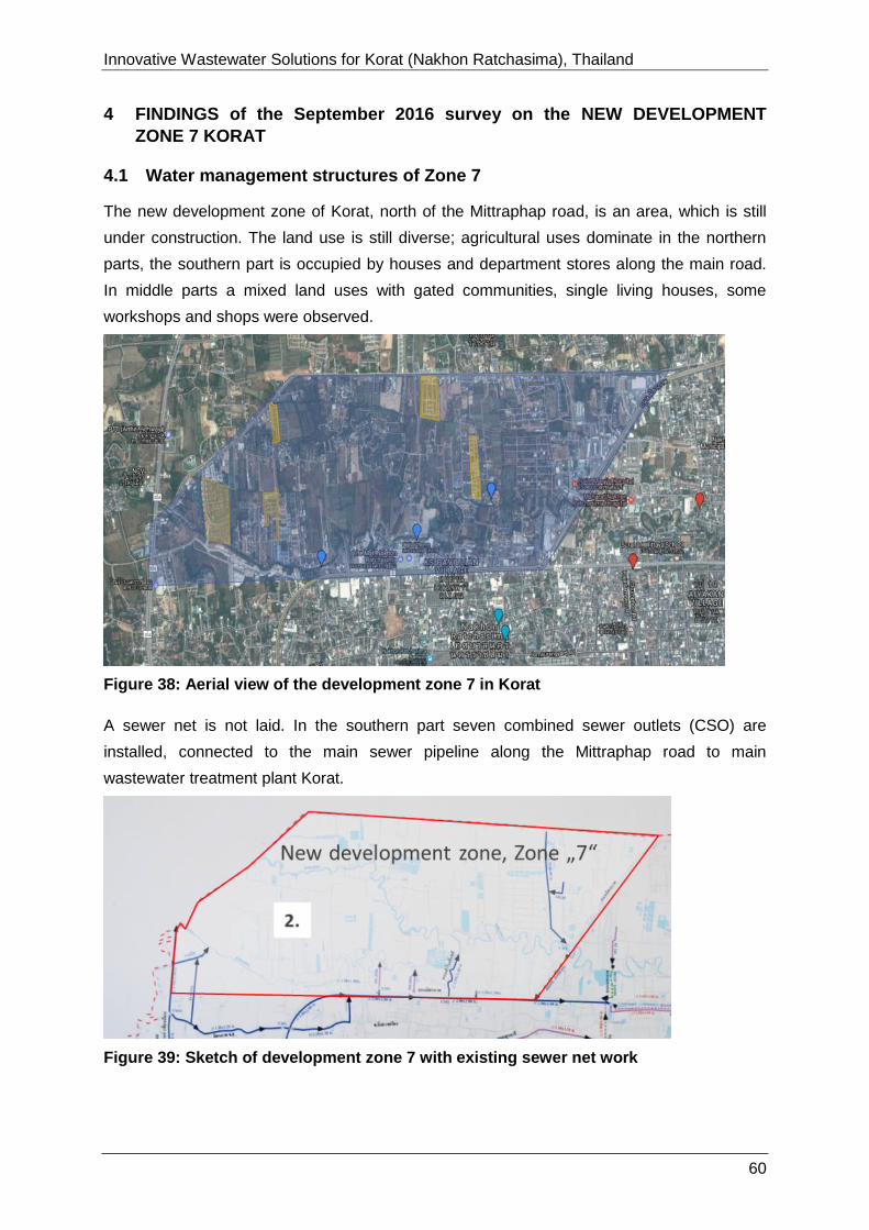
Innovative Wastewater Solutions for Korat (Nakhon Ratchasima), Thailand
170726-Report_on_Korat 60
4 FINDINGS of the September 2016 survey on the NEW DEVELOPMENT
ZONE 7 KORAT
4.1 Water management structures of Zone 7
The new development zone of Korat, north of the Mittraphap road, is an area, which is still
under construction. The land use is still diverse; agricultural uses dominate in the northern
parts, the southern part is occupied by houses and department stores along the main road.
In middle parts a mixed land uses with gated communities, single living houses, some
workshops and shops were observed.
Figure 38: Aerial view of the development zone 7 in Korat
A sewer net is not laid. In the southern part seven combined sewer outlets (CSO) are
installed, connected to the main sewer pipeline along the Mittraphap road to main
wastewater treatment plant Korat.
Figure 39: Sketch of development zone 7 with existing sewer net work
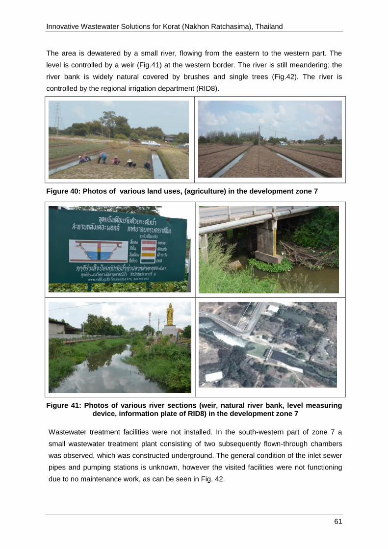
Innovative Wastewater Solutions for Korat (Nakhon Ratchasima), Thailand
170726-Report_on_Korat 61
The area is dewatered by a small river, flowing from the eastern to the western part. The
level is controlled by a weir (Fig.41) at the western border. The river is still meandering; the
river bank is widely natural covered by brushes and single trees (Fig.42). The river is
controlled by the regional irrigation department (RID8).
Figure 40: Photos of various land uses, (agriculture) in the development zone 7
Figure 41: Photos of various river sections (weir, natural river bank, level measuring device, information plate of RID8) in the development zone 7
Wastewater treatment facilities were not installed. In the south-western part of zone 7 a
small wastewater treatment plant consisting of two subsequently flown-through chambers
was observed, which was constructed underground. The general condition of the inlet sewer
pipes and pumping stations is unknown, however the visited facilities were not functioning
due to no maintenance work, as can be seen in Fig. 42.

Innovative Wastewater Solutions for Korat (Nakhon Ratchasima), Thailand
170726-Report_on_Korat 62
Given the suspected poor condition of at least parts of the sewer network, it cannot be
guaranteed that all of the wastewater from the connected parts of the city arrives at the
wastewater treatment plant.
Figure 42: Wastewater facilities in Zone 7, left: decentralised treatment system, right: Waterflow under combined sewer overflow pipe
The area of Zone 7 is still not fully developed. The already built housing areas are not
connected to the centralized wastewater drain system. Agricultural areas are partly watered
by the river and dewatered into an open drain system. The river water is polluted by the
effluents of seven combined sewer overflows (CSO) (Figure 43).
Figure 43: Sketch of the Development Zone 7, with indicated spots of the combined sewer (drainage) overflows and the natural river (green belt)
Innovative Wastewater Solutions for Korat (Nakhon Ratchasima), Thailand
170726-Report_on_Korat 63
CSO are simple infrastructural works inside of a combined sewer or drain system. During
periods of heavy rainfall, the additional volume in combined sewers system can exceed the
capacity of the drain system. During these occasions combined sewer systems are designed
to overflow and discharge the excess directly to the river without reaching the sewage
treatment plant. These overflows contain not only land drainage (run-off rainwater), but also
wastewater and debris. High levels of nutrients like Total Nitrogen and Total Phosphorous
cause excessive algae and weed growth, which lowers wate quality, harms fish and other
aquatic life as a result of lower oxygen levels.
As the waste water management system is not well developed there are high potentials for
the introduction of “new” energy-saving technologies, such as decentralized and or semi-
decentralized systems.
4.2 Conceptual recommendations for the wastewater management in Zone 7
The conceptual recommendations for the wastewater management in Zone 7 contains short-
term, intermediate and long-term measures, as follow:
Short-term measures
• Corrective measures of the combined sewer outfalls strategy
• Protection of the natural river against pollution by surface run-off and storm water
Intermediate term measures
• Integrated urban drainage planning (Master Plan), It is recommended to conduct an
integrated urban drainage planning process..
Long-term measures
In this phase of consultancy, long-term measures will not be described. More details on the
city planning process should be made available. An integrated urban drainage plan (here
categorized as intermediate-term measure) should be conducted to priorize future actions
and to describe the interconnections of all water courses, drains, artificial reservoirs and
treatment facililties.
4.2.1 Short-term corrective measures of the combined sewer outfalls
The combined sewer system operation should be improved by measures, such as
• Developing a CSO Management strategy
• Implementing a monitoring program to identify and quantify CSO events
• Proactively eliminating wet weather flows from the Combined sewer district (zone 7)
through infrastructural upgrades
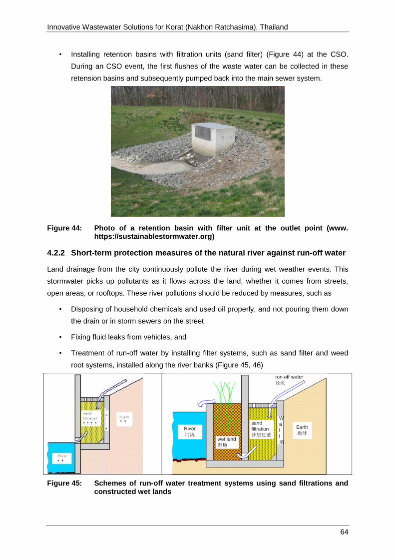
Innovative Wastewater Solutions for Korat (Nakhon Ratchasima), Thailand
170726-Report_on_Korat 64
• Installing retention basins with filtration units (sand filter) (Figure 44) at the CSO.
During an CSO event, the first flushes of the waste water can be collected in these
retension basins and subsequently pumped back into the main sewer system.
Figure 44: Photo of a retention basin with filter unit at the outlet point (www. https://sustainablestormwater.org)
4.2.2 Short-term protection measures of the natural river against run-off water
Land drainage from the city continuously pollute the river during wet weather events. This
stormwater picks up pollutants as it flows across the land, whether it comes from streets,
open areas, or rooftops. These river pollutions should be reduced by measures, such as
• Disposing of household chemicals and used oil properly, and not pouring them down
the drain or in storm sewers on the street
• Fixing fluid leaks from vehicles, and
• Treatment of run-off water by installing filter systems, such as sand filter and weed
root systems, installed along the river banks (Figure 45, 46)
Figure 45: Schemes of run-off water treatment systems using sand filtrations and constructed wet lands

Innovative Wastewater Solutions for Korat (Nakhon Ratchasima), Thailand
170726-Report_on_Korat 65
Figure 46: Photos of installed run-off water treatment systems using sand filtrations and constructed wet lands (Kirchhof, 2012)
4.3 Intermediate term measures for the wastewater management
4.3.1 Development of an integrated urban drainage plan (Master Plan)
It is recommended to develop an general integrated urban drainage plan.
Many of the problems that the city wastewater authorities face are partly caused by the lack
of an overall planning for the city’s sewer network and water treatment facilities.
One main problem is currently that the wastewater pumped into the main wastewater
treatment plant is organically much lower loaded as designed. This fact is due to degradation
processes in the drainage system and dilution processes due to wrong pipe connections or
infiltration of surface or rain water to the sewer network. Apart from the main pipes, the exact
location and condition of many combined sewers are mostly unknown. Extensions of the
sewer network and new facilities are planned as reaction to local problems and taking little to
no account of the rest of the downstream network or future developments. This can lead to
various problems (overloaded sewers, not properly working pumping stations etc.) resulting
in regular overflow from the sewers into nearby waterbodies.

Innovative Wastewater Solutions for Korat (Nakhon Ratchasima), Thailand
170726-Report_on_Korat 66
Figure 47: Core elements and topics of an integrated urban drainage planning by DWA
In order to improve this situation, the elaboration of a master plan is highly recommendable.
The DWA working paper A100 gives an overview on how to realize such a master plan,
calling it an “integrated urban drainage plan”. It emphasizes the importance of an in-depth
data acquisition from the target area (Step 3) as well as a functional and economical
evaluation of the sewer network and treatment facility condition (Step 4) before elaborating a
set of measures for the whole system (Step 5 and 6) and prioritization of these measures
(Step 7).
Given the suspected poor condition of at least parts of the sewer network, it cannot be
guaranteed that all of the wastewater from the connected parts of the city arrives at the
wastewater treatment plant.
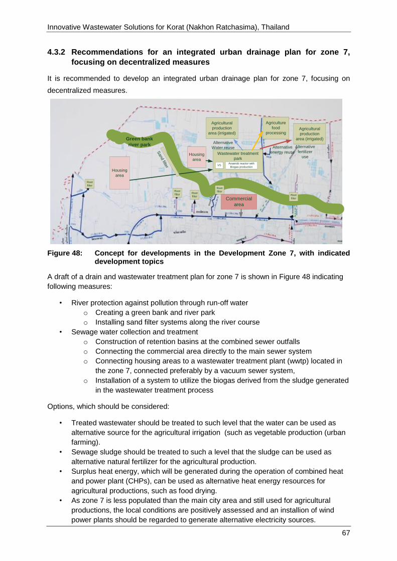
Innovative Wastewater Solutions for Korat (Nakhon Ratchasima), Thailand
170726-Report_on_Korat 67
4.3.2 Recommendations for an integrated urban drainage plan for zone 7,
focusing on decentralized measures
It is recommended to develop an integrated urban drainage plan for zone 7, focusing on
decentralized measures.
Figure 48: Concept for developments in the Development Zone 7, with indicated development topics
A draft of a drain and wastewater treatment plan for zone 7 is shown in Figure 48 indicating
following measures:
• River protection against pollution through run-off water
o Creating a green bank and river park
o Installing sand filter systems along the river course
• Sewage water collection and treatment
o Construction of retention basins at the combined sewer outfalls
o Connecting the commercial area directly to the main sewer system
o Connecting housing areas to a wastewater treatment plant (wwtp) located in
the zone 7, connected preferably by a vacuum sewer system,
o Installation of a system to utilize the biogas derived from the sludge generated
in the wastewater treatment process
Options, which should be considered:
• Treated wastewater should be treated to such level that the water can be used as
alternative source for the agricultural irrigation (such as vegetable production (urban
farming).
• Sewage sludge should be treated to such a level that the sludge can be used as
alternative natural fertilizer for the agricultural production.
• Surplus heat energy, which will be generated during the operation of combined heat
and power plant (CHPs), can be used as alternative heat energy resources for
agricultural productions, such as food drying.
• As zone 7 is less populated than the main city area and still used for agricultural
productions, the local conditions are positively assessed and an installion of wind
power plants should be regarded to generate alternative electricity sources.
Green bank
river park
Agricultural
production
area (irrigated)
Housing
area
Housing
area
Commercial
area
Root
filter
Wastewater treatment
park
Alternative
Water reuse Alternative
energy reuse
Alternative
fertilizer
use
Root
filter
Root
filterRoot
filter
Root
filter
Sand filte
r
Agriculture
food
processing
VSAnaerob reactor with
Biogas production
Agricultural
production
area (irrigated)

Innovative Wastewater Solutions for Korat (Nakhon Ratchasima), Thailand
170726-Report_on_Korat 68
5 ANNEXES
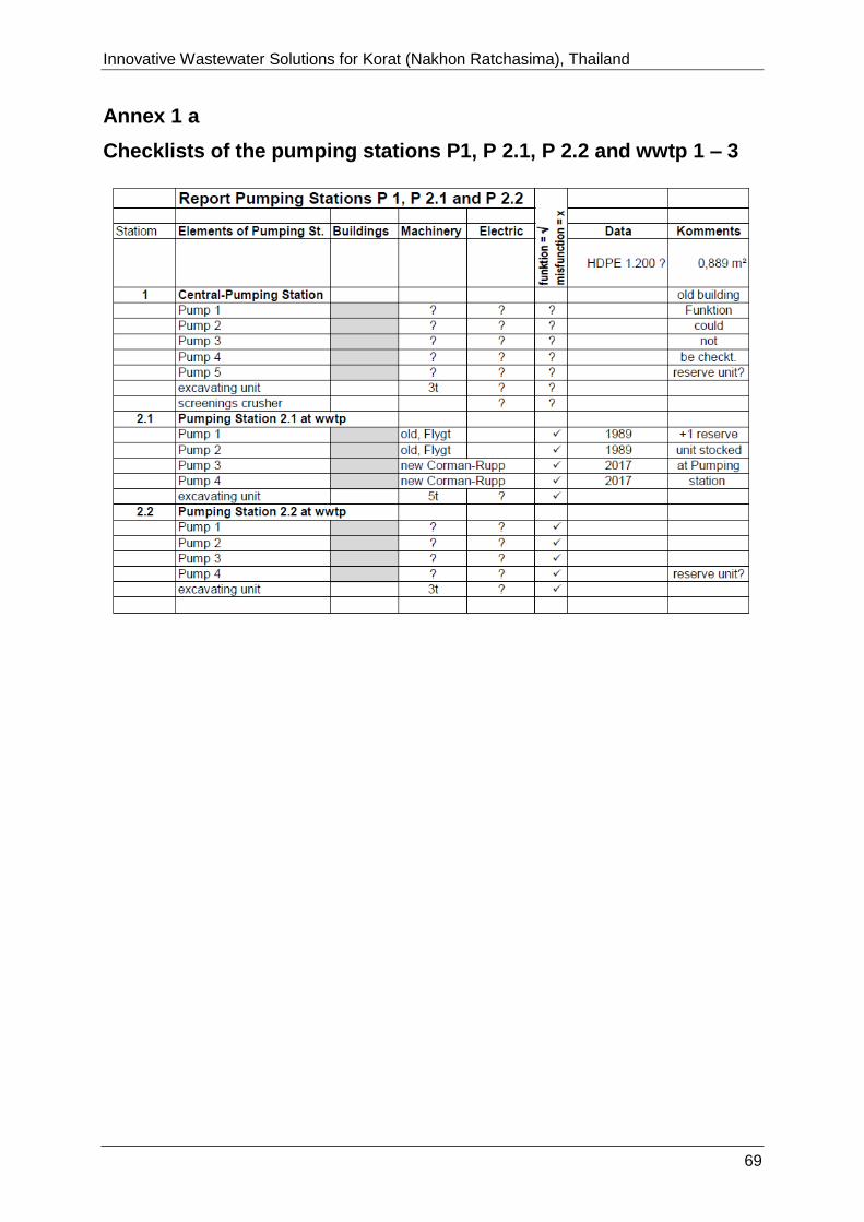
Innovative Wastewater Solutions for Korat (Nakhon Ratchasima), Thailand
170726-Report_on_Korat 69
Annex 1 a
Checklists of the pumping stations P1, P 2.1, P 2.2 and wwtp 1 – 3
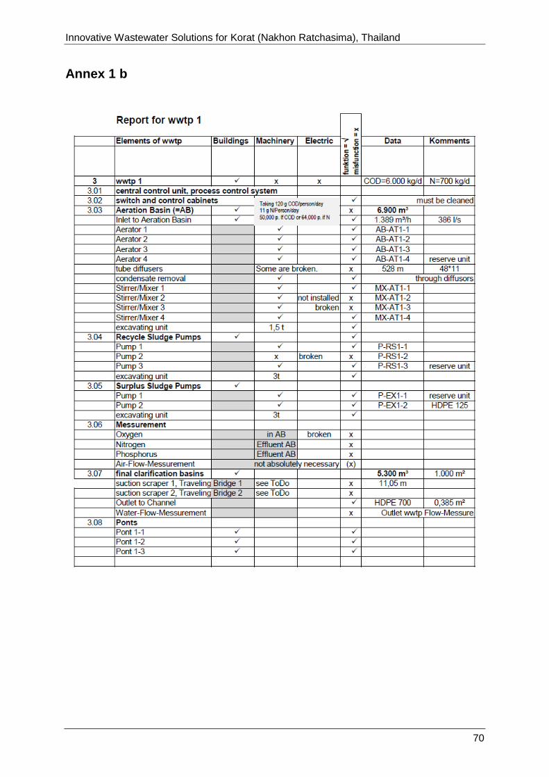
Innovative Wastewater Solutions for Korat (Nakhon Ratchasima), Thailand
170726-Report_on_Korat 70
Annex 1 b

Innovative Wastewater Solutions for Korat (Nakhon Ratchasima), Thailand
170726-Report_on_Korat 71
Annex 1 c

Innovative Wastewater Solutions for Korat (Nakhon Ratchasima), Thailand
170726-Report_on_Korat 72
Annex 1 d
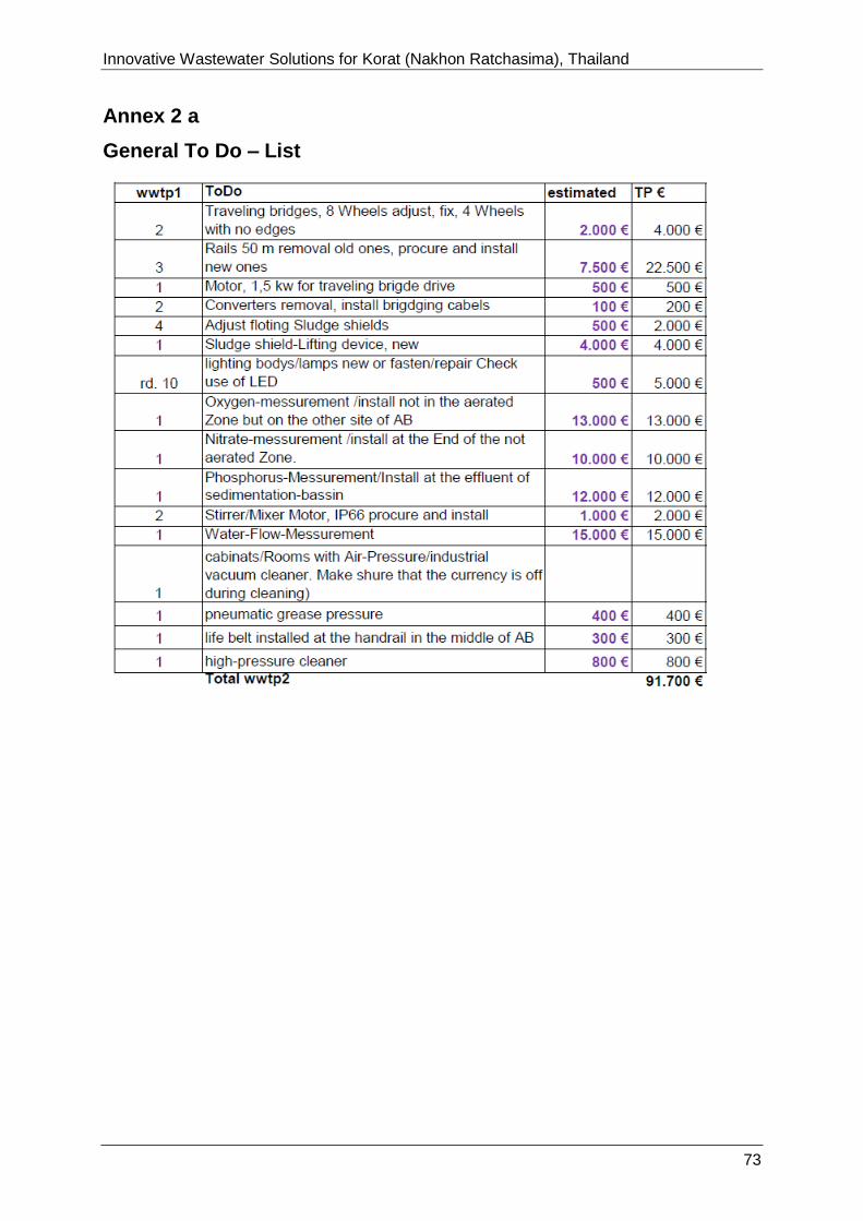
Innovative Wastewater Solutions for Korat (Nakhon Ratchasima), Thailand
170726-Report_on_Korat 73
Annex 2 a
General To Do – List

Innovative Wastewater Solutions for Korat (Nakhon Ratchasima), Thailand
170726-Report_on_Korat 74
Annex 2 b
General To Do – List

Innovative Wastewater Solutions for Korat (Nakhon Ratchasima), Thailand
170726-Report_on_Korat 75
Annex 2 c
General To Do – List
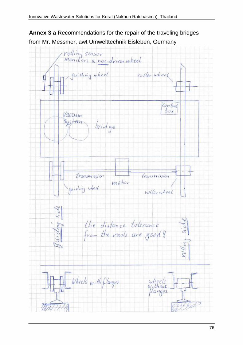
Innovative Wastewater Solutions for Korat (Nakhon Ratchasima), Thailand
170726-Report_on_Korat 76
Annex 3 a Recommendations for the repair of the traveling bridges
from Mr. Messmer, awt Umwelttechnik Eisleben, Germany
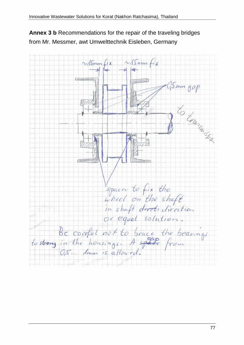
Innovative Wastewater Solutions for Korat (Nakhon Ratchasima), Thailand
170726-Report_on_Korat 77
Annex 3 b Recommendations for the repair of the traveling bridges
from Mr. Messmer, awt Umwelttechnik Eisleben, Germany
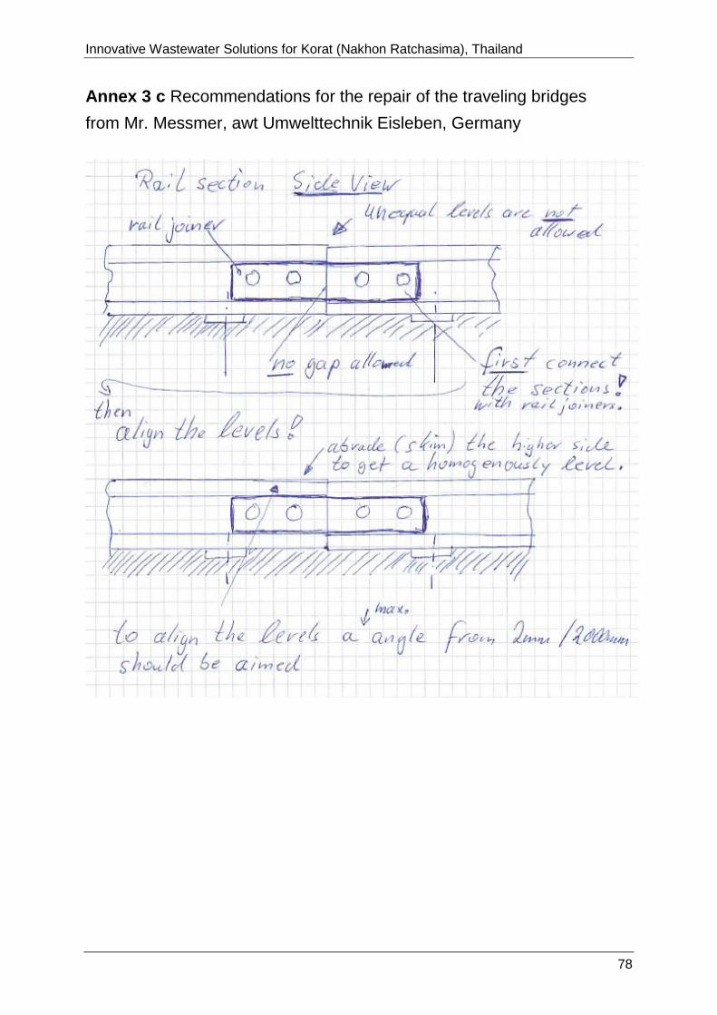
Innovative Wastewater Solutions for Korat (Nakhon Ratchasima), Thailand
170726-Report_on_Korat 78
Annex 3 c Recommendations for the repair of the traveling bridges
from Mr. Messmer, awt Umwelttechnik Eisleben, Germany

Innovative Wastewater Solutions for Korat (Nakhon Ratchasima), Thailand
170726-Report_on_Korat 79
Annex 4: Calculation matrix to calculate basic data for a PV-plant
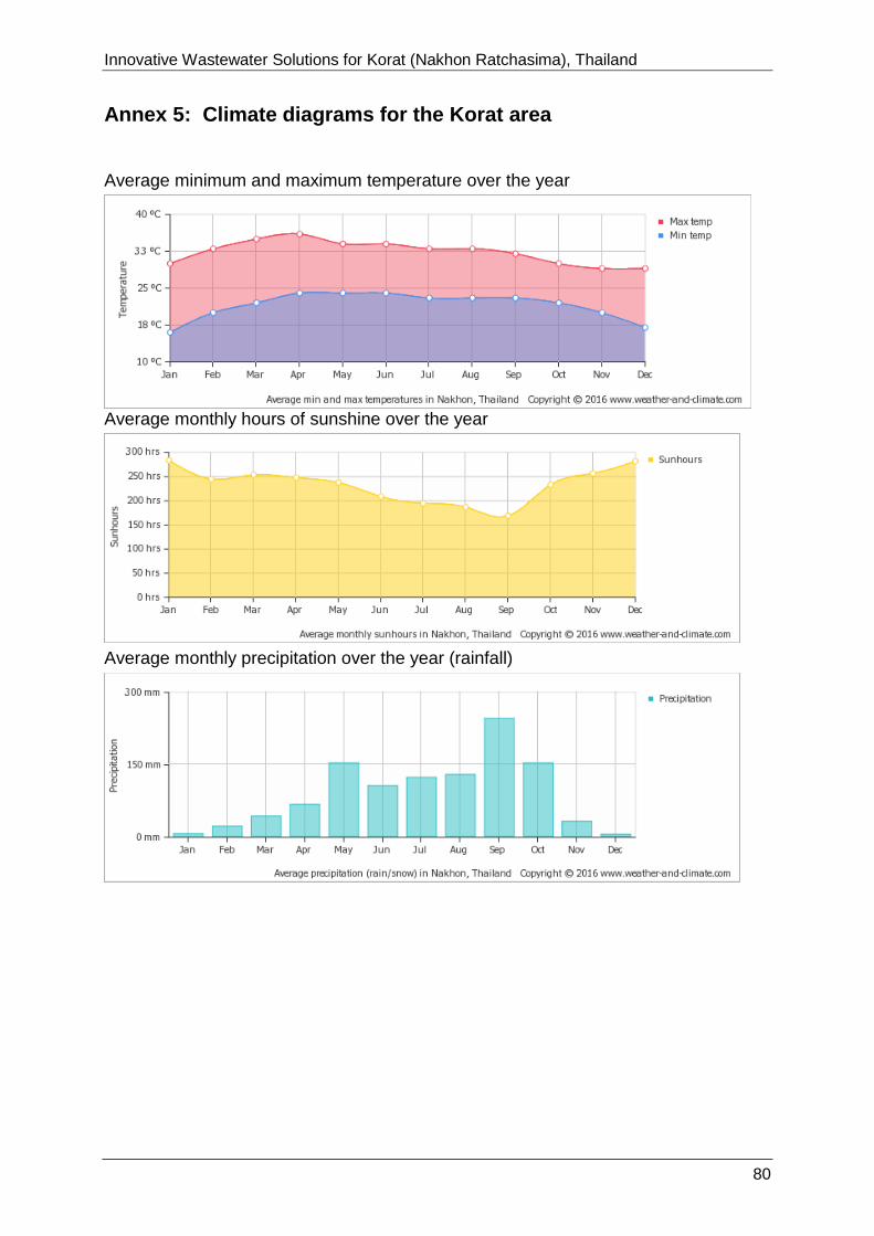
Innovative Wastewater Solutions for Korat (Nakhon Ratchasima), Thailand
170726-Report_on_Korat 80
Annex 5: Climate diagrams for the Korat area
Average minimum and maximum temperature over the year
Average monthly hours of sunshine over the year
Average monthly precipitation over the year (rainfall)