Embed Size (px)
Citation preview
Integrated Radiation Measurement and Radiation Protection of BESⅢ
Zhang Qingjiang ,Wu Qingbiao
@Radiation protection group ,accelerator center, IHEP,
2008-3-12
outline
• 1.Introduction of BESⅢ• 2.Radiation analysis of BESⅢ• 3.Radiation measurement around BESⅢ• 4.Radiation protection of BESⅢ —FLUKA simulation of collimator• 5.Shielding design to BESIII• 6.Summary
1. Introduction of BESⅢ
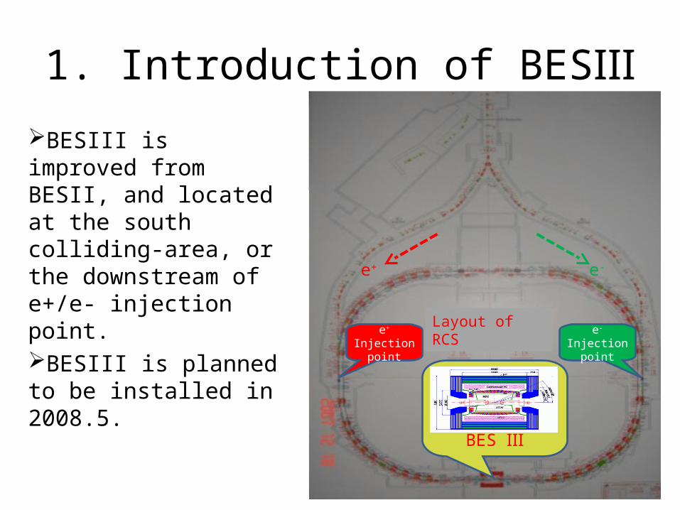
BESIII is improved from BESII, and located at the south colliding-area, or the downstream of e+/e- injection point.BESIII is planned to be installed in 2008.5.
BES Ⅲ
e-
Injection pointe+
Injection point
e+ e-
Layout of RCS
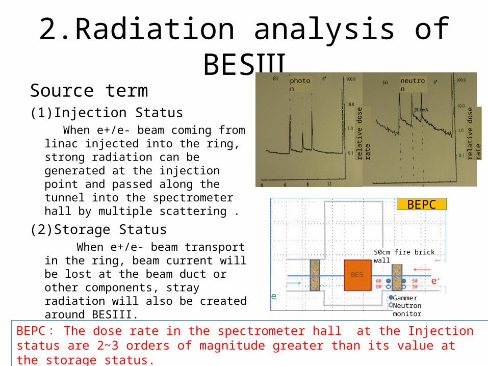
2.Radiation analysis of BESⅢSource term(1)Injection Status When e+/e- beam coming from linac
injected into the ring, strong radiation can be generated at the injection point and passed along the tunnel into the spectrometer hall by multiple scattering .
(2)Storage Status When e+/e- beam transport in the
ring, beam current will be lost at the beam duct or other components, stray radiation will also be created around BESIII.
BEPC
BEPC : The dose rate in the spectrometer hall at the Injection status are 2~3 orders of magnitude greater than its value at the storage status.
rela
tive
dose
rat
e
rela
tive
dose
rat
e
photon neutron
50cm fire brick wall
Gammer monitorNeutron monitor
e-
e+
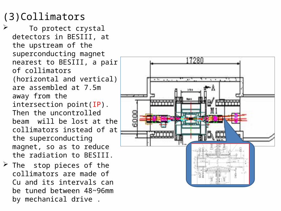
(3)Collimators To protect crystal detectors in
BESIII, at the upstream of the superconducting magnet nearest to BESIII, a pair of collimators (horizontal and vertical) are assembled at 7.5m away from the intersection point(IP). Then the uncontrolled beam will be lost at the collimators instead of at the superconducting magnet, so as to reduce the radiation to BESIII.
The stop pieces of the collimators are made of Cu and its intervals can be tuned between 48~96mm by mechanical drive .
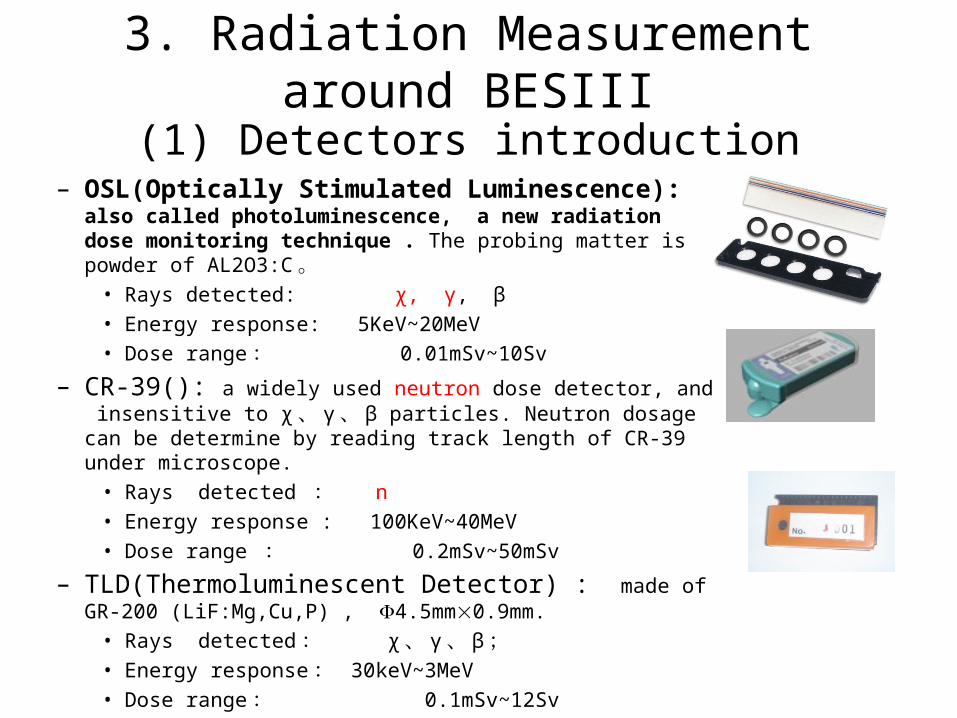
(1) Detectors introduction– OSL(Optically Stimulated Luminescence): also called
photoluminescence, a new radiation dose monitoring technique . The probing matter is powder of AL2O3:C 。
• Rays detected: χ, γ, β• Energy response: 5KeV~20MeV• Dose range : 0.01mSv~10Sv
– CR-39(): a widely used neutron dose detector, and insensitive to χ 、 γ 、 β particles. Neutron dosage can be determine by reading track length of CR-39 under microscope.
• Rays detected : n• Energy response : 100KeV~40MeV• Dose range : 0.2mSv~50mSv
– TLD(Thermoluminescent Detector) : made of GR-200 (LiF:Mg,Cu,P) , 4.5mm0.9mm.
• Rays detected : χ 、 γ 、 β ; • Energy response : 30keV~3MeV• Dose range : 0.1mSv~12Sv
3. Radiation Measurement around BESIII
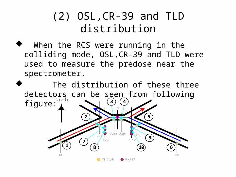
(2) OSL,CR-39 and TLD distribution
When the RCS were running in the colliding mode, OSL,CR-39 and TLD were used to measure the predose near the spectrometer.
The distribution of these three detectors can be seen from following figure:
IP
00.26m0.26m
2.1m
6m
2.1m
6m
1.75m1.75m
Pin Diode RadFET
1
2
3 4
5
67
8
9
10
North
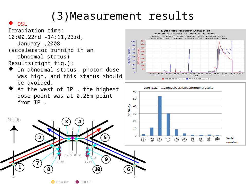
(3)Measurement results OSLIrradiation time:10:00,22nd -14:11,23rd, January ,2008(accelerator running in an abnormal
status)Results(right fig.): In abnormal status, photon dose was
high, and this status should be avoided.
At the west of IP , the highest dose point was at 0.26m point from IP .
IP
00.26m0.26m
2.1m
6m
2.1m
6m
1.75m1.75m
Pin Diode RadFET
1
2
3 4
5
67
8
9
10
North
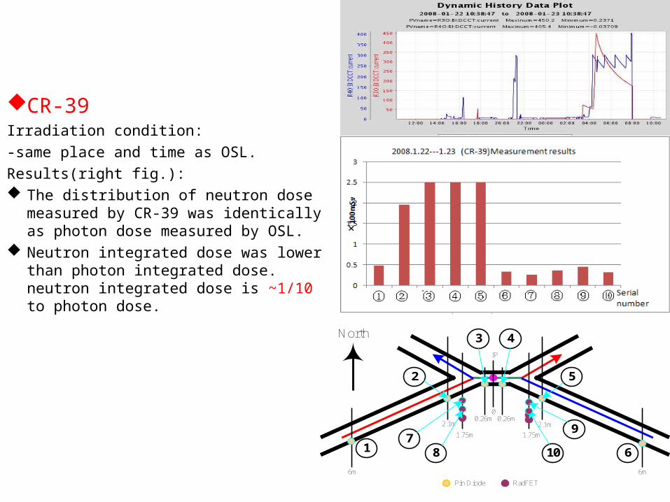
CR-39Irradiation condition:-same place and time as OSL.Results(right fig.): The distribution of neutron dose
measured by CR-39 was identically as photon dose measured by OSL.
Neutron integrated dose was lower than photon integrated dose. neutron integrated dose is ~1/10 to photon dose.
IP
00.26m0.26m
2.1m
6m
2.1m
6m
1.75m1.75m
Pin Diode RadFET
1
2
3 4
5
67
8
9
10
North
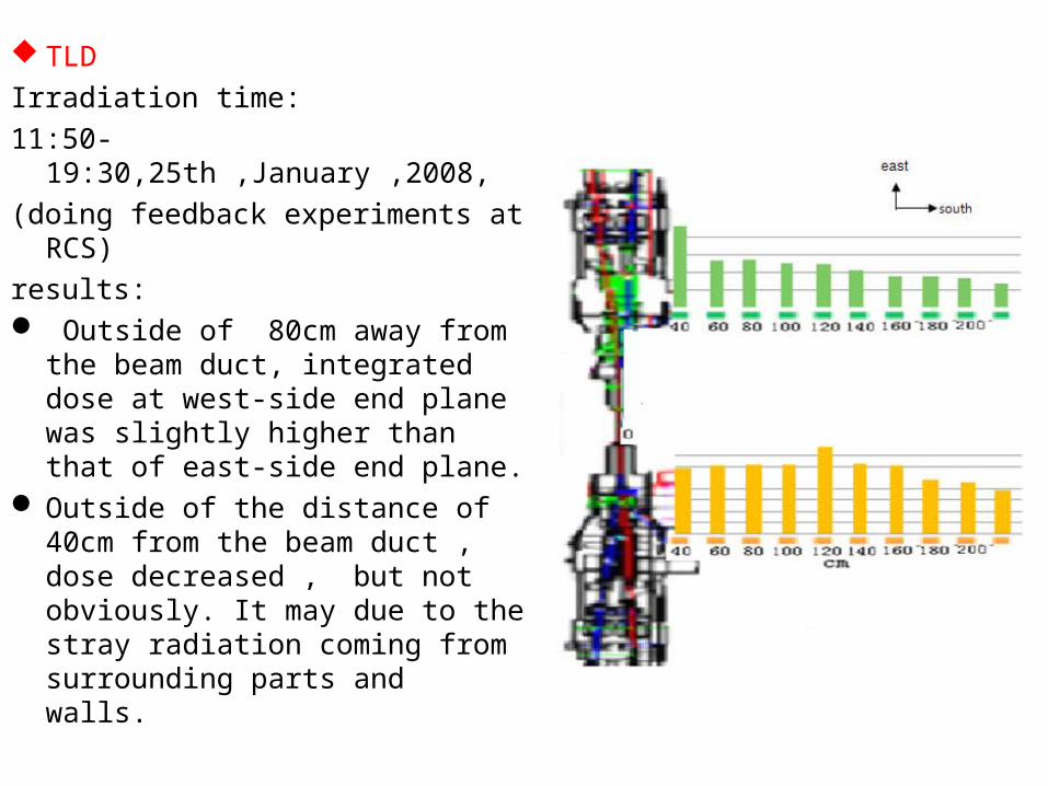
TLDIrradiation time:11:50-
19:30,25th ,January ,2008,(doing feedback experiments at
RCS)results: Outside of 80cm away from the
beam duct, integrated dose at west-side end plane was slightly higher than that of east-side end plane.
Outside of the distance of 40cm from the beam duct , dose decreased , but not obviously. It may due to the stray radiation coming from surrounding parts and walls.
Measurement result shows:
• In these extreme irradiation cases, dose rate at the colliding area were high . These extreme cases should be avoided as far as possible.
• To better protect BESIII, better shielding measures should be studied and adopted.
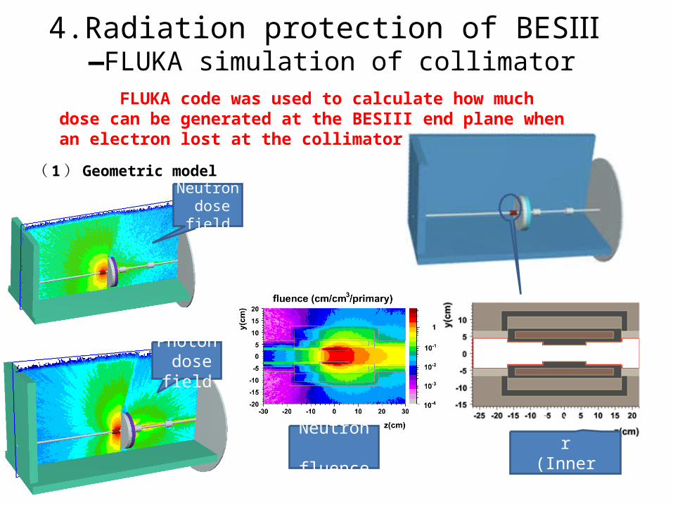
4.Radiation protection of BESⅢ —FLUKA simulation of collimator
FLUKA code was used to calculate how much dose can be generated at the BESIII end plane when an electron lost at the collimator.
( 1 ) Geometric model
Neutron dose field
Photon dose field
Neutron fluence
collimator(Inner model)
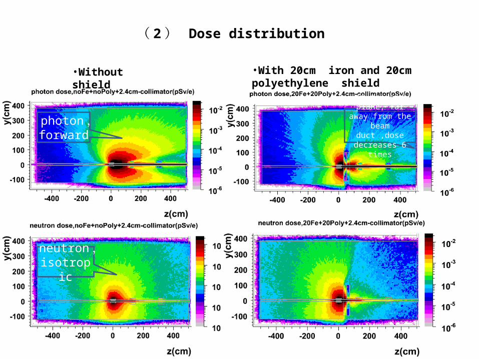
( 2 ) Dose distribution
•Without shield •With 20cm iron and 20cm polyethylene shield
photon ,forward
neutron ,isotropic
At the end plane, far away from the beam duct ,dose decreases
6 times
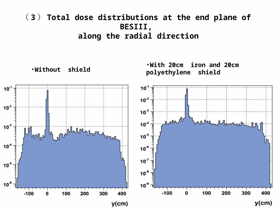
( 3 ) Total dose distributions at the end plane of BESIII, along the radial direction
•Without shield •With 20cm iron and 20cm polyethylene shield
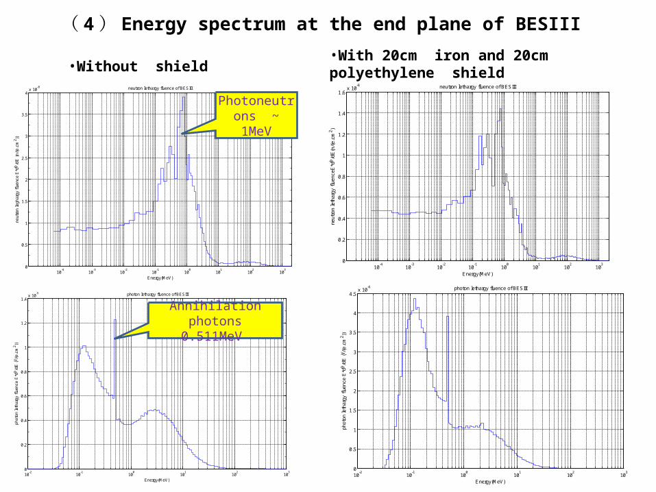
( 4 ) Energy spectrum at the end plane of BESIII
10-4
10-3
10-2
10-1
100
101
102
103
0
0.5
1
1.5
2
2.5
3
3.5
4x 10
-8 neutron lethargy fluence of BESIII
Energy(MeV)
neut
ron
legh
argy
flu
ence
E*d
/dE
(n/
(e.c
m2 ))
10-2
10-1
100
101
102
103
0
0.2
0.4
0.6
0.8
1
1.2
1.4x 10
-5 photon lethargy fluence of BESIII
Energy(MeV)
phot
on le
thar
gy f
luen
ce E
*d /
dE ( /
(e.c
m2 ))
10-2
10-1
100
101
102
103
0
0.5
1
1.5
2
2.5
3
3.5
4
4.5x 10
-6 photon lethargy fluence of BESIII
Energy(MeV)
phot
on le
thar
gy f
luen
ce E
*d /
dE ( /
(e.c
m2 ))
10-4
10-3
10-2
10-1
100
101
102
103
0
0.2
0.4
0.6
0.8
1
1.2
1.4
1.6x 10
-8 neutron lethargy fluence of BESIII
Energy(MeV)
neut
ron
leth
argy
flu
ence
E*d
/dE
(n/(
e.cm
2 )
Annihilation photons0.511MeV
Photoneutrons ~ 1MeV
•Without shield •With 20cm iron and 20cm polyethylene shield
( 5 ) Analysis on calculation results
When an electron loses at the collimator, the average dose at the end plane of BESIII with 20cm iron and 20cm polyethylene shield is 6 times lower than that without shield, namely 6E-4pSv/e and 1E-4pSv/e respectively.
As there are gaps between the magnets and the beam duct, especially the secondary particles scatters forward along the beam duct, the radiation dose within 15cm away from the beam duct outer surface almost not reduces.
Without shield, neutron dose at the end plane of BESIII is 1/10 of photon dose; As shield added, the difference decreases, and neutron dose is 1/2~1/3 to photon dose.
From energy spectrum ,we can see : Neutron energy centralized at ~1MeV , neutron number at
100keV—3MeV accounts for >90% to total neutrons . Photon energy centralized at ~100keV , photon number at 30keV—30MeV accounts for >99% to total photons.
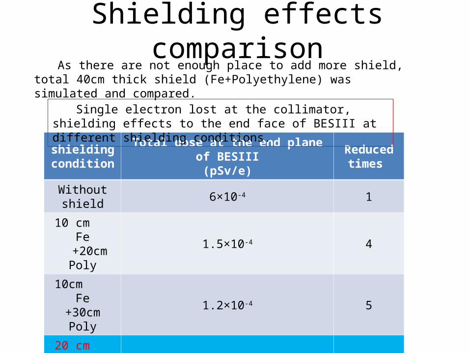
Shielding effects comparison
shielding condition
Total dose at the end plane of BESIII(pSv/e)
Reduced times
Without shield 6×10⁻⁴ 1
10 cm Fe +20cm Poly 1.5×10⁻⁴ 4
10cm Fe +30cm Poly 1.2×10⁻⁴ 5
20 cm Fe +20cm Poly 1.0×10⁻⁴ 6
40cm Fe 9.0×10⁻⁵ 7
Single electron lost at the collimator, shielding effects to the end face of BESIII at different shielding conditions.
As there are not enough place to add more shield, total 40cm thick shield (Fe+Polyethylene) was simulated and compared.
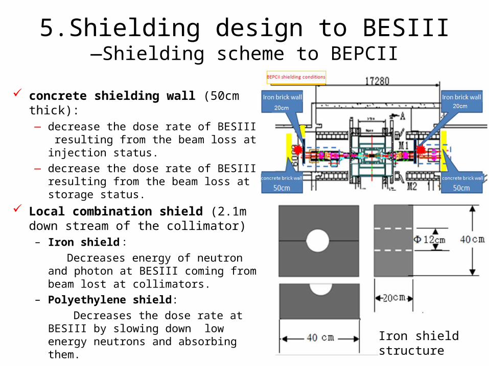
5.Shielding design to BESIII—Shielding scheme to BEPCII
concrete shielding wall (50cm thick):— decrease the dose rate of BESIII resulting
from the beam loss at injection status.— decrease the dose rate of BESIII resulting
from the beam loss at storage status. Local combination shield (2.1m down
stream of the collimator)– Iron shield : Decreases energy of neutron and photon
at BESIII coming from beam lost at collimators.
– Polyethylene shield: Decreases the dose rate at BESIII by
slowing down low energy neutrons and absorbing them.
Iron shield structure
Summary• BEPCII brings new challenges on radiation protection as compared to
BEPC, especially at protecting detectors of BESIII.• Radiation distribution around BES were measured using OSL,Ⅲ CR-39 and TLD detectors. Neutron dose was ~1/10 to photon dose. • FLUKA was adopted to study the radiation protection conditions
when collimators near BESIII was used, 20cm iron shield +15cm polyethylene shield are adopted.
• Any suggestions or questions?
Thanks for your attention!