Embed Size (px)
Citation preview

Solberg Manufacturing, Inc., 1151 Ardmore Itasca, IL 60143 USA Ph: 630.773.1363 Fax: 630.773.0727 Email: [email protected] Web: www.solbergmfg.com
Note: Please read the maintenance instructions given by the OEM for the machinery first. The OEM's manual should be adhered to in order to protect the equipment. Solberg Manufacturing, Inc has made every effort to make sure that these instructions are accurate but is not responsible for any typos, slight variations or for human errors that may occur.
Integrated Liquid Separators LRS Series 3/4” – 6” Flange
www.solbergmfg.com

Solberg Manufacturing, Inc., 1151 Ardmore Itasca, IL 60143 USA
Ph: 630.773.1363 Fax: 630.773.0727 Email: [email protected] Web: www.solbergmfg.com
Page 2
Maintenance Manual Integrated Liquid Separators
LRS Series 3/4" – 6” Flange
CONTENTS
Section A Introduction ....................................................................................... pg. 3
Section B General Information 1. Identification of Solberg Liquid Removal Systems ............. pg. 3
2. Filtration Rules of Thumb .................................................. pg. 4 3. Element Specifications. ..................................................... pg. 6 4. Element Cleaning .............................................................. pg. 7
Section C Procedures
1. Installation ......................................................................... pg. 8 2. Disconnecting Canister Base from Canister Top............... pg. 9 3. Removing Element for Service/Maintenance. ................... pg. 10 4. Securing Element .............................................................. pg. 11 5. Securing Canister Top to Canister Base. .......................... pg. 12 6. Equipment Startup ............................................................ pg. 13
Section D Maintenance Recommendations 1. General .............................................................................. pg. 14 2. Replacement Parts List ..................................................... pg. 15
*For Further Information Please Call: 630-773-1363

Solberg Manufacturing, Inc., 1151 Ardmore Itasca, IL 60143 USA
Ph: 630.773.1363 Fax: 630.773.0727 Email: [email protected] Web: www.solbergmfg.com
Page 3
Section A INTRODUCTION
The purpose of this manual is instruction on the proper assembly and care of Solberg inlet air filters.
*WARNING* This manual must be read and thoroughly understood before using and caring for this air filter. Failure to comply could result in explosion, product/system contamination or personal injury.
This manual should be used as a supplement to the user’s understanding of the proper care needed to maintain a safe and dependable LRS unit. It is the responsibility of the user to interpret and explain all instructions to persons who do not read or understand English BEFORE they are allowed to maintain and use this LRS unit.
This manual should be readily available to all operators responsible for operation and maintenance of the LRS unit.
We thank you for selecting products from Solberg Manufacturing, Inc. We are confident that our superior filter designs will meet your application requirements.
Section B GENERAL INFORMATION
1. Identification of Solberg Liquid Removal Systems. All Solberg liquid removal systems should have an identification label/nameplate that gives the following information:
Assembly Model # Replacement Element #
Fill in the actual nameplate data from your new Solberg unit(s) in Table 1:
Solberg Manufacturing, Inc., 1151 Ardmore Itasca, IL 60143 USA
Ph: 630.773.1363 Fax: 630.773.0727 Email: [email protected] Web: www.solbergmfg.com
Page 4
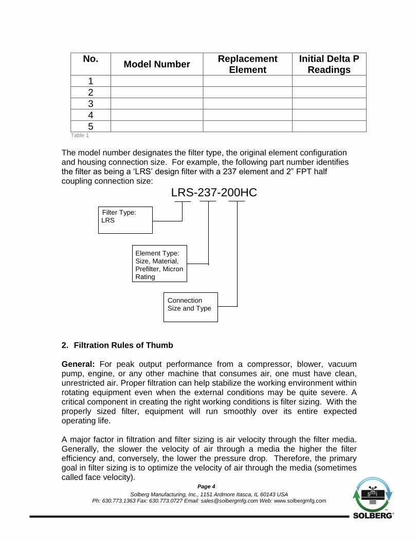
No. Model Number
Replacement Element
Initial Delta P Readings
1
2
3
4
5 Table 1
The model number designates the filter type, the original element configuration and housing connection size. For example, the following part number identifies the filter as being a ‘LRS’ design filter with a 237 element and 2” FPT half coupling connection size:
LRS-237-200HC
Filter Type: LRS
Element Type: Size, Material, Prefilter, Micron Rating
Connection Size and Type
2. Filtration Rules of Thumb General: For peak output performance from a compressor, blower, vacuum pump, engine, or any other machine that consumes air, one must have clean, unrestricted air. Proper filtration can help stabilize the working environment within rotating equipment even when the external conditions may be quite severe. A critical component in creating the right working conditions is filter sizing. With the properly sized filter, equipment will run smoothly over its entire expected operating life. A major factor in filtration and filter sizing is air velocity through the filter media. Generally, the slower the velocity of air through a media the higher the filter efficiency and, conversely, the lower the pressure drop. Therefore, the primary goal in filter sizing is to optimize the velocity of air through the media (sometimes called face velocity).

Solberg Manufacturing, Inc., 1151 Ardmore Itasca, IL 60143 USA
Ph: 630.773.1363 Fax: 630.773.0727 Email: [email protected] Web: www.solbergmfg.com
Page 5
Rule of Thumb #1: Always begin with the filter cartridge requirements when sizing a filter. Once the appropriate element has been selected, move on to the housing requirements. Rule of Thumb #2: Always ask or specify a filter based on a micron rating with filtration efficiencies. As an example, stating a requirement for a 1-micron filter is misleading because no efficiency rating has been specified. A 1-micron filter at 95% efficiency may be less efficient than a 5-micron filter at 99% efficiency. For proper air system performance in light and industrial duty environments, a filter with a minimum of 99% filtration efficiency at 5 microns is required. Rule of Thumb #3: Size your filter correctly by understanding the impact air velocity through a media has on efficiency and pressure drop. Maintain the suggested Air-to-Media ratios listed below based on the external environment listings and Filtration efficiency needs.
Filtration Efficiency Requirements (99%+ efficiency)
Environmental Conditions
Air to Media Ratio
Industrial Grade 2-micron Paper
Industrial Duty (clean, office/warehouse-like) 30 CFM/ft2 (51m3/h)/cm2
Severe Duty (workshop, factory-like) 15 CFM/ft2 (25.5m3/h)/cm2
Extreme Duty (Foundry, Construction-like) 10 CFM/ft2 (17m3/h)/cm2
Industrial Grade 5-micron Polyester
Industrial Duty (clean, office/warehouse-like) 50 CFM/ft2 (85m3/h)/cm2
Severe Duty (workshop, factory-like) 40 CFM/ft2 (68m3/h)/cm2
Extreme Duty (Foundry, Construction-like) 25 CFM/ft2 (42.5m3/h)/cm2
Industrial Grade 1-micron Polyester
Severe Duty (Foundry, Construction-like) 10 CFM/ft2 (17m3/h)/cm2
Industrial Grade 0.3-micron HEPA Glass @ 99.97% Efficiency
Industrial Duty (Pre-filtered Applications) 10 CFM/ft2 (17m3/h)/cm2
Severe Duty (workshop, factory-like) 7 CFM/ft2 (12m3/h)/cm2
Extreme Duty (Foundry, Construction-like) 5 CFM/ft2 (8.5m3/h)/cm2
Table 2

Solberg Manufacturing, Inc., 1151 Ardmore Itasca, IL 60143 USA
Ph: 630.773.1363 Fax: 630.773.0727 Email: [email protected] Web: www.solbergmfg.com
Page 6
Rule of Thumb #4: Pressure drop is also caused by the dirt holding capacity of the element. As the element fills up with dirt, the pressure drop increases. It is important to document the pressure drop across a given filter when it is new and then clean or replace it when the pressure drop increases by 10” to 15” / 250-280mm H2O over the original reading. Rule of Thumb #5: The inlet connection greatly influences the overall pressure drop of the filter system. To minimize the restriction contributed by an inlet filter, a velocity of 6,000 ft/min (10200m3/h) or less is suggested through the outlet pipe. The table below lists the suggested flows based on pipe size:
Pipe Size (inches)
Max Airflow Pipe Size (inches)
Max Airflow Pipe Size (inches)
Airflow
1/4" 6 CFM 10m3/h 1 ½" 80 CFM 136m
3/h 6" 1,100 CFM 1870m
3/h
3/8" 8 CFM 14m3/h 2" 135 CFM 230m
3/h 8" 1,800 CFM 3060m
3/h
1/2" 10 CFM 17m3/h 2 ½" 195 CFM 332m
3/h 10" 3,300 CFM 5610m
3/h
3/4" 20 CFM 34m3/h 3" 300 CFM 510m
3/h 12" 4,700 CFM 7990m
3/h
1" 35 CFM 60m3/h 4" 520 CFM 884m
3/h 14" 6,000 CFM 10200m
3/h
1 ¼" 60 CFM 102m3/h 5" 800 CFM 1360m
3/h
Table 3 *Note: This information is for general use only. A qualified engineer must properly design each system.
3. Element Specifications Temperature Range: -15° to 220°F / -26° to 105°C Filter Change-Out Differential: 10” to 15” / 250-380mm H2O Over Initial Delta P
Media
Micron Rating
Standard Paper 99+% @ 2 micron
Standard Polyester 99+% @ 5 micron
“S” Series Wire Mesh Epoxy Coated Wire Mesh
“Z” Series Polyester 99+% @ 1 micron
“HE” Series HEPA 99.97% @ 0.3 microns
“U” Series Polyester 99+% @ 25 micron
“W” Series Polyester 99+% @ 100 micron
“S2” Series Stainless Steel Wire Mesh
“AC” & “ACP” Series N/A
“Y” Series Polypropylene 99+% @ 5 micron Table 4
Temperature Range: -15° to 385°F / -26° to 196°C Filter Change-Out Differential: 10” to 15”/ 250-380mm H2O Over Initial Delta P
Media Micron Rating
“MX” & “MXD” Series – Nomex Cloth 99+% @ 5 micron Table 5

Solberg Manufacturing, Inc., 1151 Ardmore Itasca, IL 60143 USA
Ph: 630.773.1363 Fax: 630.773.0727 Email: [email protected] Web: www.solbergmfg.com
Page 7
4. Element Cleaning - Inlet Filtration Solberg elements should be cleaned or replaced, once the pressure drop reaches 15 to 20-inches water column (380 - 500mm WC) above the initial pressure drop of the installation. The decision to clean the element rather than replace it is left to the discretion of the operator. Any damage which results from by-pass or additional pressure drop created by element cleaning is the sole responsibility of the operator.
*WARNING* The overall performance of a filter element is altered once cleaned. The initial pressure drop after cleaning will be greater than the original, clean pressure drop of the element. After each subsequent cleaning, the initial pressure drop will continue to increase. Under all circumstances, the initial pressure drop of the element needs to be maintained at less than 20-inches water column (500mm WC). Cleaned elements that exceed 20-inches water column (500mm WC) at start-up should be replaced with new elements.
With many types of equipment, the maximum pressure drop allowed will be dictated by the ability of the equipment to perform to its rated capacity. Under all circumstances, the operator should avoid exceeding the manufacturer’s recommended maximum pressure drop for their specific equipment.
A. Polyester Element: The polyester element may be washed in warm soapy water, vacuumed, gently blown out or replaced. The element should be dry before reinstallation. The element should be replaced after a maximum of three cleanings.
B. Paper Element: The paper element may be lightly blown with low pressure air. It is disposable and in most cases should be replaced with a new element.

Solberg Manufacturing, Inc., 1151 Ardmore Itasca, IL 60143 USA
Ph: 630.773.1363 Fax: 630.773.0727 Email: [email protected] Web: www.solbergmfg.com
Page 8
C. Polyurethane Prefilter: The prefilter may be washed as a sponge or replaced to give the element a longer service life.
D. Epoxy Coated Wire Mesh and Stainless Steel Wire Mesh Elements: Cleaning instructions similar to polyester, except mild solvents may be used.
E. Activated Carbon Element: Not cleanable F. Polypropylene Element: Cleaning instructions similar to polyester G. Nomex Cloth Element: Cleaning instructions similar to polyester
If you are not confident that the integrity of the element was maintained during cleaning, it is recommended that a new element be installed. Also, spare parts such as gaskets, wing nuts and washers can be supplied upon request.
Section C PROCEDURES
1. Installation.
Figure C.1.1: Housing terms.

Solberg Manufacturing, Inc., 1151 Ardmore Itasca, IL 60143 USA
Ph: 630.773.1363 Fax: 630.773.0727 Email: [email protected] Web: www.solbergmfg.com
Page 9
A. Maximum operating temperature for most Solberg inlet air filter products is 220°F / 105°C. Temperatures in excess of this could cause damage to elements, media and elastomers. High temperature products are available.
B. Direction of flow is typically from the outside of the element to the inside of
the element. Most products have arrows indicating direction of flow on the inlet and outlet ports.
C. Ensure that pipe connections are adequately sealed so the potential for
leaks is reduced to a minimum.
2. Disconnecting Canister Base from Canister Top.
A. Remove V-band by loosening nut or T-handle and releasing. Remove housing base and O-ring slowly.
Figure C.2.1: V-Band.
Figure C.2.2: Canister base removal. Figure C.2.3: Canister base and O-ring free from housing.

Solberg Manufacturing, Inc., 1151 Ardmore Itasca, IL 60143 USA
Ph: 630.773.1363 Fax: 630.773.0727 Email: [email protected] Web: www.solbergmfg.com
Page 10
3. Removing Element for Service/Maintenance.
A. Remove retaining hex head/wing-nut and washer carefully, and then remove element.
B. Clean sealing surfaces of housing and element endcaps so that they are free of dirt or any other particulate.
Figure C.3.1: Retaining washer and wing-nut.
Figure C.3.2: Element removal. Figure C.3.3: Element free from housing.

Solberg Manufacturing, Inc., 1151 Ardmore Itasca, IL 60143 USA
Ph: 630.773.1363 Fax: 630.773.0727 Email: [email protected] Web: www.solbergmfg.com
Page 11
*WARNING*
Failure to comply with these instructions may result in system or equipment contamination.
4. Securing Element.
A. Place new or cleaned element evenly on base plate by inserting threaded bolt through bolt hole on the element end cap. Be sure the element seats properly in the housing top and there is no dirt or particulate present on sealing surfaces.
B. Secure element with washer and wing nut to end cap and bolt. Element must be tightly secured. Note: DO NOT over tighten!
*WARNING*
Defective installation may cause system or pump contamination. Use only genuine Solberg replacement parts.
Figure C.4.1: Element secure in housing assembly.

Solberg Manufacturing, Inc., 1151 Ardmore Itasca, IL 60143 USA
Ph: 630.773.1363 Fax: 630.773.0727 Email: [email protected] Web: www.solbergmfg.com
Page 12
5. Securing Canister Top to Canister Base.
A. Make sure all surfaces are free from dust and other particulate.
B. Hemisphere O-ring must rest evenly along canister base O-ring groove, see figure C.5.1.
C. Secure V-band by disconnecting hex nut or T-bolt portion and placing V-band along the diameter of canister O-ring groove. Fasten nut or T-handle and secure tightly. V-BAND LEGS MUST REST UNIFORMLY ALONG ENTIRE O-RING GROOVE! See figures C.5.2 and C.5.3.
Figure C.5.1: Correct placement of O-ring in O-ring groove.
Figure C.5.2: Correct placement of V-Band.
Figure C.5.3: Detailed V-Band placement along O-ring groove.

Solberg Manufacturing, Inc., 1151 Ardmore Itasca, IL 60143 USA
Ph: 630.773.1363 Fax: 630.773.0727 Email: [email protected] Web: www.solbergmfg.com
Page 13
6. Equipment Startup. A. Be sure to read the instructions on installation or element replacement as
listed above before starting equipment.
*WARNING*
If at any time the operator is unable to verify the integrity of the element or any housing feature, the factory or a regional representative should be contacted prior to start-up.
B. Please check the listed steps prior to startup.
1. Check element to make sure it is seated properly in housing top.
*WARNING*
Failure to seat the element properly may result in contaminant by-pass resulting in damage to equipment.
2. Check that the housing base and V-band is installed correctly.
*WARNING*
If the air flow is reversed through a Solberg filter unit, be sure to check the element and housing internals for damage. Failure to do so may result in damage to equipment.
3. Be sure all fasteners and hardware have been tightened.

Solberg Manufacturing, Inc., 1151 Ardmore Itasca, IL 60143 USA
Ph: 630.773.1363 Fax: 630.773.0727 Email: [email protected] Web: www.solbergmfg.com
Page 14
Section D MAINTENANCE RECOMMENDATIONS
1. Pressure drop readings are recommended to have an effective air filter. Always document initial pressure drop during start-up when element is clean. Replacement cartridge is needed when system experiences 10” to 15” / 250-380mm H2O above drop above the initial reading. Refer to page 4 for initial values.
2. Always check replacement cartridge gaskets to insure they are adhered uniformly along the end caps during handling. If not, contact Solberg Manufacturing, Inc. immediately. Do not modify or change from Solberg specified parts!
3. Always check inlets/outlets, element base and its components when replacing element to insure cleanliness. Wipe clean if necessary.
4. Operate only when a proper seal exists.
5. Never operate without absolute assurance that V-band is secured correctly along entire diameter of canisters. Check along V-band for wear. Replace if any distortion occurs due to handling and usage.
Solberg Manufacturing, Inc., 1151 Ardmore Itasca, IL 60143 USA
Ph: 630.773.1363 Fax: 630.773.0727 Email: [email protected] Web: www.solbergmfg.com
Page 15
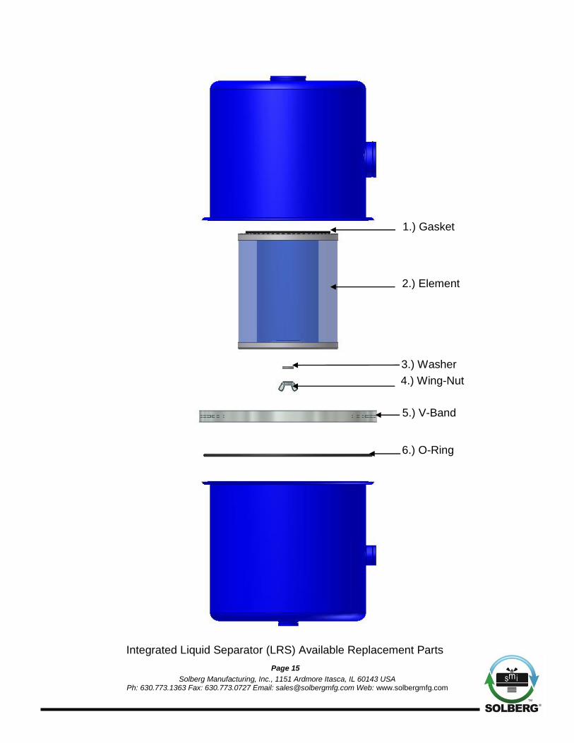
Integrated Liquid Separator (LRS) Available Replacement Parts
5.) V-Band
2.) Element
1.) Gasket
3.) Washer
4.) Wing-Nut
6.) O-Ring

Solberg Manufacturing, Inc., 1151 Ardmore Itasca, IL 60143 USA
Ph: 630.773.1363 Fax: 630.773.0727 Email: [email protected] Web: www.solbergmfg.com
Page 16
Available Replacement Part by Product Number
Product # Element** Gasket Washer Wing-Nut V-Band O-Ring
LRS-19-XXX 19 N/A 5040200 5030500 5050100 9241400
LRS-237-XXX 237 9110001 5020150 5030600 5050400 9241610
LRS-275-XXX 275 9110200 5020150 5030600 5060150 9241700
**Note: Even element numbers are Paper elements and odd element numbers are Polyester elements.