Embed Size (px)
Citation preview

Instruction Manual
0558012268 09/2014
Integrated Gas Control (IGC) System - Vision 5x
(use with EPP-202/362 Power Sources) for cut data see manual: 0558011611

2
Integrated Gas Control (IGC) System - Vision 5x
3
Integrated Gas Control (IGC) System - Vision 5x
This equipment will perform in conformity with the description thereof contained in this manual and accompa-nying labels and/or inserts when installed, operated, maintained and repaired in accordance with the instruc-tions provided. This equipment must be checked periodically. Malfunctioning or poorly maintained equipment should not be used. Parts that are broken, missing, worn, distorted or contaminated should be replaced imme-diately. Should such repair or replacement become necessary, the manufacturer recommends that a telephone or written request for service advice be made to the Authorized Distributor from whom it was purchased.
This equipment or any of its parts should not be altered without the prior written approval of the manufacturer. The user of this equipment shall have the sole responsibility for any malfunction which results from improper use, faulty maintenance, damage, improper repair or alteration by anyone other than the manufacturer or a ser-vice facility designated by the manufacturer.
Be sure this information reaches the operator.You can get extra copies through Your supplier.
these instructions are for experienced operators. if you are not fully familiar with the principles of operation and safe practices for arc welding and cutting equipment, we urge you to read our booklet, “precautions and safe practices for arc Welding, cutting, and gouging,” form 52-529. Do not permit untrained persons to install, operate, or maintain this equipment. Do not attempt to install or operate this equipment until you have read and fully understand these instructions. if you do not fully understand these instructions, contact your supplier for further information. Be sure to read the safety precautions be-fore installing or operating this equipment.
user responsiBilitY
reaD anD unDerstanD the instruction manual Before installing or operating.
protect Yourself anD others!
caution

4
Integrated Gas Control (IGC) System - Vision 5x
5
Integrated Gas Control (IGC) System - Vision 5x
table of contents
safety
safety - english .................................................................................................................................................11Safety - Spanish .................................................................................................................................................................................. 15
Safety - French .................................................................................................................................................................................... 19
system Diagram
system Diagrams ..............................................................................................................................................25Base System + WIC + ACC (all options) ..................................................................................................................................... 26
Descriptions
power supplies .................................................................................................................................................29380/400V Power Supplies ...............................................................................................................................................................29
460/575V Power Supplies ...............................................................................................................................................................29
380/400V Power Supplies ...............................................................................................................................................................30
460/575V Power Supplies ...............................................................................................................................................................30
combined gas control (cgc) ...........................................................................................................................31Specifications ...................................................................................................................................................................................... 31
Connections ........................................................................................................................................................................................ 32
CGC Flow Diagram ............................................................................................................................................................................ 35
Combined Gas Control Plumbing Schematic ..........................................................................................................................36
Combined Gas Control Electrical Schematic ........................................................................................................................... 37
CGC Mounting Dimensions ...........................................................................................................................................................38
CGC Bottom View ..............................................................................................................................................................................38
Troubleshooting ................................................................................................................................................................................ 39
Replacement Parts ............................................................................................................................................................................ 39

6
Integrated Gas Control (IGC) System - Vision 5x
remote arc starter (ras) ................................................................................................................................ 40Specifications ......................................................................................................................................................................................40
Remote Arc Starter Connections ................................................................................................................................................. 41
RAS Box Mounting Dimensions ................................................................................................................................................... 43
RAS Box Mounting Plate Dimensions ........................................................................................................................................ 43
Typical / Recommended E-stop Connection ...........................................................................................................................44
Replacement Parts ............................................................................................................................................................................44
air curtain control (acc) .................................................................................................................................45Specifications ......................................................................................................................................................................................45
ACC Mounting Dimensions ............................................................................................................................................................46
ACC Component Connections ......................................................................................................................................................46
Water injection control (Wic) ..........................................................................................................................47Specifications ...................................................................................................................................................................................... 47
automatic height control (ahc) .................................................................................................................... 48Specifications ......................................................................................................................................................................................48
B4 Mounting Dimensions ...............................................................................................................................................................49
hoses and cables ..............................................................................................................................................50Specifications ...................................................................................................................................................................................... 55
pt-36 mechanized plasmarc cutting torch ....................................................................................................55Package Options Available ...........................................................................................................................................................56
Optional Accessories ........................................................................................................................................................................56
PT-36 Torch Consumable Kits ........................................................................................................................................................ 57
Recommended Regulators ............................................................................................................................................................ 59
Replacement Parts ............................................................................................................................................................................ 59

7
Integrated Gas Control (IGC) System - Vision 5x
installation
grounding .........................................................................................................................................................63Introduction ........................................................................................................................................................................................63
Grounding Overview .......................................................................................................................................................................64
Basic Layout ........................................................................................................................................................................................65
Elements of a Ground System .......................................................................................................................................................66
Plasma Current Return Path ..........................................................................................................................................................66
Plasma System Safety Ground ...................................................................................................................................................... 67
Rail System Safety Ground ............................................................................................................................................................. 70
Earth Ground Rod ............................................................................................................................................................................. 71
Ground Rod ......................................................................................................................................................................................... 71
Soil Resistivity ..................................................................................................................................................................................... 71
Utility Power Electrical Ground ....................................................................................................................................................72
Multiple Ground Rods .....................................................................................................................................................................73
Machine Grounding Schematic.................................................................................................................................................... 74
Check upon receipt .......................................................................................................................................................................... 75
Before Installation ............................................................................................................................................................................. 75
placement of power supply .............................................................................................................................75Connection Procedures .................................................................................................................................................................. 75
placement of ras Box ......................................................................................................................................76Connections on the RAS Box ........................................................................................................................................................ 76
torch connections ............................................................................................................................................79Connection of Torch to Plasma System .....................................................................................................................................80
Connection to the Remote Arc Starter Box ..............................................................................................................................80
Mounting Torch to Machine ........................................................................................................................................................ 81
Preparing to Cut.................................................................................................................................................................................84
placement of cgc ............................................................................................................................................ 90Individual Component Connections ..........................................................................................................................................90
ACC Component Connections ...................................................................................................................................................... 91

8
Integrated Gas Control (IGC) System - Vision 5x
maintenance/troubleshootingTorch Front End Disassembly ........................................................................................................................................................95
Torch Front End Assembly .............................................................................................................................................................98
Torch Front End Assembly using the Speedloader ...............................................................................................................99
Torch Front End Disassembly (for Production Thick Plate) ...............................................................................................100
Torch Front End Assembly (for Production Thick Plate) .....................................................................................................103
Torch Body Maintenance ...........................................................................................................................................................105
Torch Body Removal and Replacement ..................................................................................................................................106
Reduced Consumable Life ........................................................................................................................................................108
Checking for Coolant Leaks .........................................................................................................................................................109
replacement partsGeneral ................................................................................................................................................................................................ 113
Ordering ............................................................................................................................................................................................. 113

safety

SAFETY
11
safety - english
Warning: these safety precautions are for your protection. they summarize precautionary information from the references listed in additional safety
information section. Before performing any instal-lation or operating procedures, be sure to read and follow the safety precautions listed below as well as all other manuals, material safety data sheets, labels, etc. failure to observe safety precautions can result in injury or death.
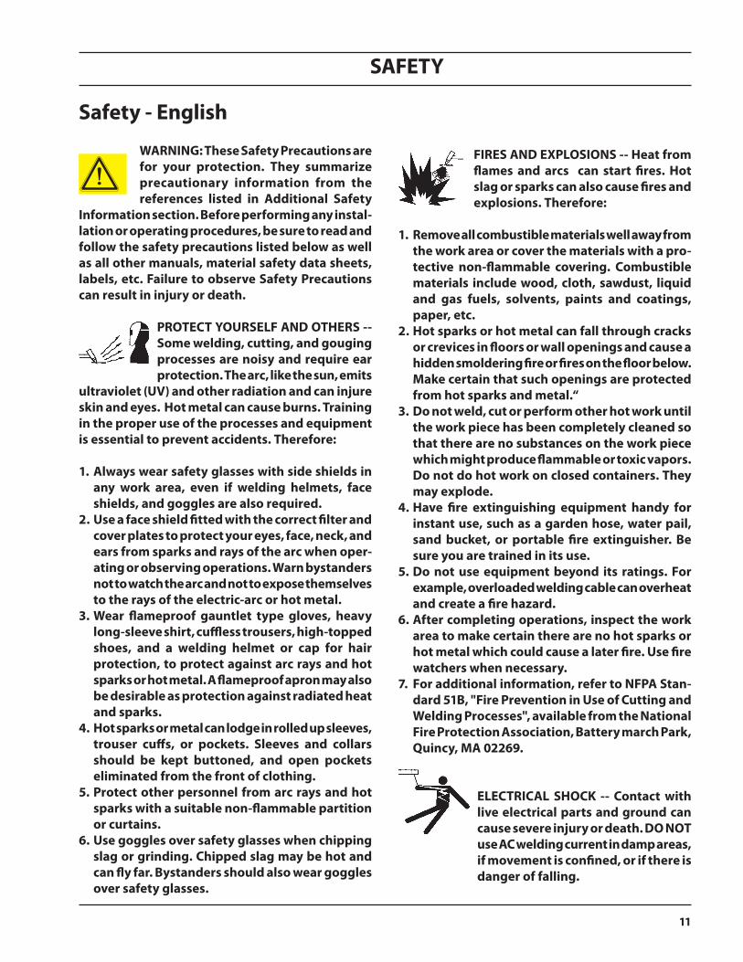
protect Yourself anD others -- some welding, cutting, and gouging processes are noisy and require ear protection. the arc, like the sun, emits
ultraviolet (uV) and other radiation and can injure skin and eyes. hot metal can cause burns. training in the proper use of the processes and equipment is essential to prevent accidents. therefore:
1. always wear safety glasses with side shields in any work area, even if welding helmets, face shields, and goggles are also required.
2. use a face shield fitted with the correct filter and cover plates to protect your eyes, face, neck, and ears from sparks and rays of the arc when oper-ating or observing operations. Warn bystanders not to watch the arc and not to expose themselves to the rays of the electric-arc or hot metal.
3. Wear flameproof gauntlet type gloves, heavy long-sleeve shirt, cuffless trousers, high-topped shoes, and a welding helmet or cap for hair protection, to protect against arc rays and hot sparks or hot metal. a flameproof apron may also be desirable as protection against radiated heat and sparks.
4. hot sparks or metal can lodge in rolled up sleeves, trouser cuffs, or pockets. sleeves and collars should be kept buttoned, and open pockets eliminated from the front of clothing.
5. protect other personnel from arc rays and hot sparks with a suitable non-flammable partition or curtains.
6. use goggles over safety glasses when chipping slag or grinding. chipped slag may be hot and can fly far. Bystanders should also wear goggles over safety glasses.
fires anD explosions -- heat from flames and arcs can start fires. hot slag or sparks can also cause fires and explosions. therefore:
1. remove all combustible materials well away from the work area or cover the materials with a pro-tective non-flammable covering. combustible materials include wood, cloth, sawdust, liquid and gas fuels, solvents, paints and coatings, paper, etc.
2. hot sparks or hot metal can fall through cracks or crevices in floors or wall openings and cause a hidden smoldering fire or fires on the floor below. make certain that such openings are protected from hot sparks and metal.“
3. Do not weld, cut or perform other hot work until the work piece has been completely cleaned so that there are no substances on the work piece which might produce flammable or toxic vapors. Do not do hot work on closed containers. they may explode.
4. have fire extinguishing equipment handy for instant use, such as a garden hose, water pail, sand bucket, or portable fire extinguisher. Be sure you are trained in its use.
5. Do not use equipment beyond its ratings. for example, overloaded welding cable can overheat and create a fire hazard.
6. after completing operations, inspect the work area to make certain there are no hot sparks or hot metal which could cause a later fire. use fire watchers when necessary.
7. for additional information, refer to nfpa stan-dard 51B, "fire prevention in use of cutting and Welding processes", available from the national fire protection association, Battery march park, Quincy, ma 02269.
electrical shocK -- contact with live electrical parts and ground can cause severe injury or death. Do not use ac welding current in damp areas, if movement is confined, or if there is danger of falling.

SAFETY
12
1. Be sure the power source frame (chassis) is con-nected to the ground system of the input power.
2. Connect the work piece to a good electrical ground.
3. Connect the work cable to the work piece. A poor or missing connection can expose you or others to a fatal shock.
4. Use well-maintained equipment. Replace worn or damaged cables.
5. Keep everything dry, including clothing, work area,
cables, torch/electrode holder, and power source.
6. Make sure that all parts of your body are insulated from work and from ground.
7. Do not stand directly on metal or the earth while working in tight quarters or a damp area; stand on dry boards or an insulating platform and wear rubber-soled shoes.
8. Put on dry, hole-free gloves before turning on the power.
9. Turn off the power before removing your gloves.
10. Refer to ANSI/ASC Standard Z49.1 (listed on next page) for specific grounding recommenda-tions. Do not mistake the work lead for a ground cable.
electric anD magnetic fielDs — may be dangerous. electric current flowing through any
conductor causes localized electric and magnetic fields (emf). Weld-ing and cutting current creates emf around welding cables and welding machines. therefore:
1. Welders having pacemakers should consult their physician before welding. EMF may interfere with some pacemakers.
2. Exposure to EMF may have other health effects which are unknown.
3. Welders should use the following procedures to minimize exposure to EMF:
A. Route the electrode and work cables together. Secure them with tape when possible.
B. Never coil the torch or work cable around your body.
C. Do not place your body between the torch and work cables. Route cables on the same side of your body.
D. Connect the work cable to the work piece as close as possible to the area being welded.
E. Keep welding power source and cables as far away from your body as possible.
fumes anD gases -- fumes and gases, can cause discomfort or harm, particularly in confined spaces. Do not breathe fumes and gases. shield-ing gases can cause asphyxiation.
therefore:
1. Always provide adequate ventilation in the work area by natural or mechanical means. Do not weld, cut, or gouge on materials such as galvanized steel, stain-less steel, copper, zinc, lead, beryllium, or cadmium unless positive mechanical ventilation is provided. Do not breathe fumes from these materials.
2. Do not operate near degreasing and spraying opera-tions. The heat or arc rays can react with chlorinated hydrocarbon vapors to form phosgene, a highly toxic gas, and other irritant gases.
3. If you develop momentary eye, nose, or throat ir-ritation while operating, this is an indication that ventilation is not adequate. Stop work and take necessary steps to improve ventilation in the work area. Do not continue to operate if physical discom-fort persists.
4. Refer to ANSI/ASC Standard Z49.1 (see listing below) for specific ventilation recommendations.
SAFETY
13
5. Warning: this product, when used for welding or cutting, produces fumes or gases which con-tain chemicals known to the state of california to cause birth defects and, in some cases, can-cer. (california health & safety code §25249.5 et seq.)
cYlinDer hanDling -- cylinders, if mishandled, can rupture and vio-lently release gas. sudden rupture of cylinder, valve, or relief device can injure or kill. therefore:
1. Use the proper gas for the process and use the proper pressure reducing regulator designed to operate from the compressed gas cylinder. Do not use adaptors. Maintain hoses and fittings in good condition. Follow manufacturer's operating instruc-tions for mounting regulator to a compressed gas cylinder.
2. Always secure cylinders in an upright position by chain or strap to suitable hand trucks, undercar-riages, benches, walls, post, or racks. Never secure cylinders to work tables or fixtures where they may become part of an electrical circuit.
3. When not in use, keep cylinder valves closed. Have valve protection cap in place if regulator is not con-nected. Secure and move cylinders by using suitable hand trucks. Avoid rough handling of cylinders.
4. Locate cylinders away from heat, sparks, and flames. Never strike an arc on a cylinder.
5. For additional information, refer to CGA Standard P-1, "Precautions for Safe Handling of Compressed Gases in Cylinders", which is available from Compressed Gas Association, 1235 Jefferson Davis Highway, Arlington, VA 22202.
eQuipment maintenance -- faulty or im-properly maintained equipment can cause injury or death. therefore:
1. Always have qualified personnel perform the instal-lation, troubleshooting, and maintenance work. Do not perform any electrical work unless you are qualified to perform such work.
2. Before performing any maintenance work inside a power source, disconnect the power source from the incoming electrical power.
3. Maintain cables, grounding wire, connections, power cord, and power supply in safe working order. Do not operate any equipment in faulty condition.
4. Do not abuse any equipment or accessories. Keep equipment away from heat sources such as furnaces, wet conditions such as water puddles, oil or grease, corrosive atmospheres and inclement weather.
5. Keep all safety devices and cabinet covers in position and in good repair.
6. Use equipment only for its intended purpose. Do not modify it in any manner.
aDDitional safetY information -- for more information on safe practices for electric arc welding and cutting equipment, ask your supplier for a copy of "precautions and safe practices for arc Welding, cut-ting and gouging", form 52-529.
The following publications, which are available from the American Welding Society, 550 N.W. LeJuene Road, Miami, FL 33126, are recommended to you:
1. ANSI/ASC Z49.1 - “Safety in Welding and Cutting”.2. AWS C5.1 - “Recommended Practices for Plasma Arc
Welding”.3. AWS C5.2 - “Recommended Practices for Plasma Arc
Cutting”.4. AWS C5.3 - “Recommended Practices for Air Carbon
Arc Gouging and Cutting”.5. AWS C5.5 - “Recommended Practices for Gas Tung-
sten Arc Welding“.6. AWS C5.6 - “Recommended Practices for Gas Metal
Arc Welding”.7. AWS SP - “Safe Practices” - Reprint, Welding Hand-
book.8. ANSI/AWS F4.1, “Recommended Safe Practices for
Welding and Cutting of Containers That Have Held Hazardous Substances.”
9. CSA Standard - W117.2 = Safety in Welding, Cutting and Allied Processes.
SAFETY
14
The ip code indicates the enclosure class, i.e. the degree of protection against penetration by solid objects or water. Protection is provided against touch with a finger, penetration of solid objects greater than 12mm and against spraying water up to 60 degrees from vertical. Equipment marked ip21s may be stored, but is not in-tended to be used outside during precipitation unless sheltered.
enclosure class
this product is solely intended for plasma cutting. any other use may result in personal injury and / or equipment damage.
15°
MaximumTilt Allowed
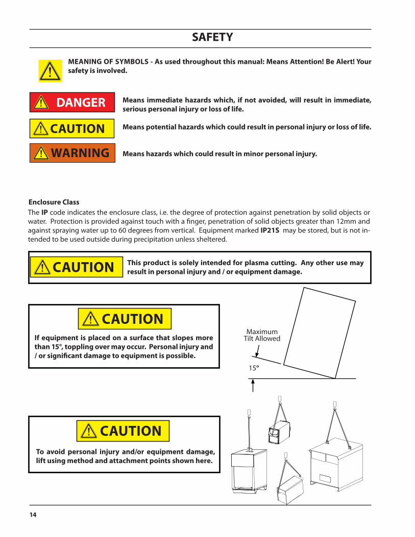
cautionif equipment is placed on a surface that slopes more than 15°, toppling over may occur. personal injury and / or significant damage to equipment is possible.
cautionto avoid personal injury and/or equipment damage, lift using method and attachment points shown here.
caution
caution
caution
means immediate hazards which, if not avoided, will result in immediate, serious personal injury or loss of life.
means potential hazards which could result in personal injury or loss of life.
means hazards which could result in minor personal injury.
meaning of sYmBols - as used throughout this manual: means attention! Be alert! Your safety is involved.
Warning
Danger
caution
SAFETY
15
safety - spanishaDVertencia: estas precauciones de seguridad son para su protección. ellas hacen resumen de información prove-
niente de las referencias listadas en la sección "información adicional sobre la seguridad". antes de hacer cualquier instalación o procedimiento de operación , asegúrese de leer y seguir las precaucio-nes de seguridad listadas a continuación así como también todo manual, hoja de datos de seguridad del material, calcomanias, etc. el no observar las precauciones de seguridad puede resultar en daño a la persona o muerte.
proteJase usteD Y a los Demas-- algunos procesos de soldadura, corte y ranurado son ruidosos y requiren protección para los oídos. el arco, como
el sol , emite rayos ultravioleta (uV) y otras radiaciones que pueden dañar la piel y los ojos. el metal caliente causa quemaduras. el entrenamiento en el uso propio de los equipos y sus procesos es esencial para prevenir accidentes. por lo tanto:
1. Utilice gafas de seguridad con protección a los lados siempre que esté en el área de trabajo, aún cuando esté usando careta de soldar, protector para su cara u otro tipo de protección.
2. Use una careta que tenga el filtro correcto y lente para proteger sus ojos, cara, cuello, y oídos de las chispas y rayos del arco cuando se esté operando y observando las operaciones. Alerte a todas las personas cercanas de no mirar el arco y no exponerse a los rayos del arco eléctrico o el metal fundido.
3. Use guantes de cuero a prueba de fuego, camisa pesada de mangas largas, pantalón de ruedo liso, zapato alto al tobillo, y careta de soldar con capucha para el pelo, para proteger el cuerpo de los rayos y chispas calientes provenientes del metal fundido. En ocaciones un delantal a prueba de fuego es necesario para protegerse del calor radiado y las chispas.
4. Chispas y partículas de metal caliente puede alojarse en las mangas enrolladas de la camisa , el ruedo del pantalón o los bolsillos. Mangas y cuellos deberán mantenerse abotonados, bolsillos al frente de la camisa deberán ser cerrados o eliminados.
5. Proteja a otras personas de los rayos del arco y chispas calientes con una cortina adecuada no-flamable como división.
6. Use careta protectora además de sus gafas de seguridad cuando esté removiendo escoria o puliendo.
la escoria puede estar caliente y desprenderse con velocidad. personas cercanas deberán usar gafas de seguridad y careta protectora.
fuego Y explosiones -- el calor de las flamas y el arco pueden ocacionar fuegos. escoria caliente y las chispas pueden causar fuegos y explosiones. por lo tanto:
1. Remueva todo material combustible lejos del área de trabajo o cubra los materiales con una cobija a prueba de fuego. Materiales combustibles incluyen madera, ropa, líquidos y gases flamables, solventes, pinturas, papel, etc.
2. Chispas y partículas de metal pueden introducirse en las grietas y agujeros de pisos y paredes causando fuegos escondidos en otros niveles o espacios. Asegúrese de que toda grieta y agujero esté cubierto para proteger lugares adyacentes contra fuegos.
3. No corte, suelde o haga cualquier otro trabajo relacionado hasta que la pieza de trabajo esté totalmente limpia y libre de substancias que puedan producir gases inflam-ables o vapores tóxicos. No trabaje dentro o fuera de contenedores o tanques cerrados. Estos pueden explotar si contienen vapores inflamables.
4. Tenga siempre a la mano equipo extintor de fuego para uso instantáneo, como por ejemplo una manguera con agua, cubeta con agua, cubeta con arena, o extintor portátil. Asegúrese que usted esta entrenado para su uso.
5. No use el equipo fuera de su rango de operación. Por ejemplo, el calor causado por cable sobrecarga en los cables de soldar pueden ocasionar un fuego.
6. Después de termirar la operación del equipo, inspeccione el área de trabajo para cerciorarse de que las chispas o metal caliente ocasionen un fuego más tarde. Tenga personal asignado para vigilar si es necesario.
7. Para información adicional , haga referencia a la pub-licación NFPA Standard 51B, "Fire Prevention in Use of Cutting and Welding Processes", disponible a través de la National Fire Protection Association, Batterymarch Park, Quincy, MA 02269.
choQue electrico -- el contacto con las partes eléc-tricas energizadas y tierra puede causar daño severo
o muerte. no use soldadura de corriente alterna (ac) en áreas húmedas, de mov-imiento confinado en lugares estrechos o si hay posibilidad de caer al suelo.
SAFETY
16
1. Asegúrese de que el chasis de la fuente de poder esté conectado a tierra através del sistema de electricidad primario.
2. Conecte la pieza de trabajo a un buen sistema de tierra física.
3. Conecte el cable de retorno a la pieza de trabajo. Cables y conductores expuestos o con malas conexiones pueden exponer al operador u otras personas a un choque eléctrico fatal.
4. Use el equipo solamente si está en buenas condi-ciones. Reemplaze cables rotos, dañados o con conductores expuestos.
5. Mantenga todo seco, incluyendo su ropa, el área de trabajo, los cables, antorchas, pinza del electrodo, y la fuente de poder.
6. Asegúrese que todas las partes de su cuerpo están insuladas de ambos, la pieza de trabajo y tierra.
7. No se pare directamente sobre metal o tierra mien-tras trabaja en lugares estrechos o áreas húmedas; trabaje sobre un pedazo de madera seco o una plataforma insulada y use zapatos con suela de goma.
8. Use guantes secos y sin agujeros antes de energizar el equipo.
9. Apage el equipo antes de quitarse sus guantes. 10. Use como referencia la publicación ANSI/ASC
Standard Z49.1 (listado en la próxima página) para recomendaciones específicas de como conectar el equipo a tierra. No confunda el cable de soldar a la pieza de trabajo con el cable a tierra.
campos electricos Y magneti-cos - son peligrosos. la corriente eléctrica fluye através de cualquier conductor causando a nivel local campos eléctricos y magnéticos
(emf). las corrientes en el área de corte y soldadura, crean emf alrrededor de los cables de soldar y las maquinas. por lo tanto: 1. Soldadores u Operadores que use marca-pasos para
el corazón deberán consultar a su médico antes de soldar. El Campo Electromagnético (EMF) puede interferir con algunos marca-pasos.
2. Exponerse a campos electromagnéticos (EMF) puede causar otros efectos de salud aún desconocidos.
3. Los soldadores deberán usar los siguientes proced-imientos para minimizar exponerse al EMF:
A. Mantenga el electrodo y el cable a la pieza de trabajo juntos, hasta llegar a la pieza que usted quiere soldar. Asegúrelos uno junto al otro con cinta adhesiva cuando sea posible.
B. Nunca envuelva los cables de soldar alrededor de su cuerpo.
C. Nunca ubique su cuerpo entre la antorcha y el cable, a la pieza de trabajo. Mantega los cables a un sólo lado de su cuerpo.
D. Conecte el cable de trabajo a la pieza de trabajo lo más cercano posible al área de la soldadura.
E. Mantenga la fuente de poder y los cables de soldar lo más lejos posible de su cuerpo.
humo Y gases -- el humo y los gases, pueden causar malestar o daño, particularmente en espacios sin ventilación. no inhale el humo o gases. el gas de protección puede
causar falta de oxígeno. por lo tanto:
1. Siempre provea ventilación adecuada en el área de trabajo por medio natural o mecánico. No solde, corte, o ranure materiales con hierro galvanizado, acero inoxidable, cobre, zinc, plomo, berílio, o cad-mio a menos que provea ventilación mecánica positiva . No respire los gases producidos por estos materiales.
2. No opere cerca de lugares donde se aplique sub-stancias químicas en aerosol. El calor de los rayos del arco pueden reaccionar con los vapores de hidrocarburo clorinado para formar un fosfógeno, o gas tóxico, y otros irritant es.
3. Si momentáneamente desarrolla inrritación de ojos, nariz o garganta mientras est á operando, es indicación de que la ventilación no es apropiada. Pare de trabajar y tome las medidas necesarias para mejorar la ventilación en el área de trabajo. No continúe operando si el malestar físico per-siste.
4. Haga referencia a la publicación ANSI/ASC Standard Z49.1 (Vea la lista a continuación) para recomen-daciones específicas en la ventilación.
SAFETY
17
5. aDVertencia-- este producto cuando se utiliza para soldaduras o cortes, produce humos o gases, los cuales contienen químicos cono-cidos por el estado de california de causar defectos en el nacimiento, o en algunos ca-sos, cancer. (california health & safety code §25249.5 et seq.)
maneJo De cilinDros-- los cilin-dros, si no son manejados correcta-mente, pueden romperse y liberar violentamente gases. rotura repen-tina del cilindro, válvula, o válvula de escape puede causar daño o muerte.
por lo tanto:
1. Utilize el gas apropiado para el proceso y utilize un regulador diseñado para operar y reducir la presión del cilindro de gas . No utilice adapta-dores. Mantenga las mangueras y las conexiones en buenas condiciones. Observe las instrucciones de operación del manufacturero para montar el regulador en el cilindro de gas comprimido.
2. Asegure siempre los cilindros en posición vertical y amárrelos con una correa o cadena adecuada para asegurar el cilindro al carro, transportes, tab-lilleros, paredes, postes, o armazón. Nunca asegure los cilindros a la mesa de trabajo o las piezas que son parte del circuito de soldadura . Este puede ser parte del circuito elélectrico.
3. Cuando el cilindro no está en uso, mantenga la válvula del cilindro cerrada. Ponga el capote de protección sobre la válvula si el regulador no está conectado. Asegure y mueva los cilindros utilizando un carro o transporte adecuado. Evite el manejo brusco de los
mantenimiento Del eQuipo -- equipo defectuoso o mal mantenido puede cau-sar daño o muerte. por lo tanto:
1. Siempre tenga personal cualificado para efec-tuar l a instalación, diagnóstico, y mantenimiento del equipo. No ejecute ningún trabajo eléctrico a menos que usted esté cualificado para hacer el trabajo.
2. Antes de dar mantenimiento en el interior de la fuente de poder, desconecte la fuente de poder del suministro de electricidad primaria.
3. Mantenga los cables, cable a tierra, conexciones, cable primario, y cualquier otra fuente de poder en buen estado operacional. No opere ningún equipo en malas condiciones.
4. No abuse del equipo y sus accesorios. Mantenga el equipo lejos de cosas que generen calor como hornos, también lugares húmedos como charcos de agua , aceite o grasa, atmósferas corrosivas y las inclemencias del tiempo.
5. Mantenga todos los artículos de seguridad y coverturas del equipo en su posición y en buenas condiciones.
6. Use el equipo sólo para el propósito que fue diseñado. No modifique el equipo en ninguna manera.
informacion aDicional De seguriDaD -- para más información sobre las prácticas de se-guridad de los equipos de arco eléctrico para soldar y cortar, pregunte a su suplidor por una copia de "precautions and safe practices for arc Welding, cutting and gouging-form 52-529.
Las siguientes publicaciones, disponibles através de la American Welding Society, 550 N.W. LeJuene Road, Miami, FL 33126, son recomendadas para usted:
1. ANSI/ASC Z49.1 - “Safety in Welding and Cutting”.2. AWS C5.1 - “Recommended Practices for Plasma Arc
Welding”.3. AWS C5.2 - “Recommended Practices for Plasma Arc
Cutting”.4. AWS C5.3 - “Recommended Practices for Air Carbon
Arc Gouging and Cutting”.5. AWS C5.5 - “Recommended Practices for Gas Tung-
sten Arc Welding“.6. AWS C5.6 - “Recommended Practices for Gas Metal
Arc Welding”.7. AWS SP - “Safe Practices” - Reprint, Welding Hand-
book.8. ANSI/AWS F4.1, “Recommended Safe Practices for
Welding and Cutting of Containers That Have Held Hazardous Substances.”
9. CSA Standard - W117.2 = Safety in Welding, Cutting and Allied Processes.
SAFETY
18
significaDo De los simBolos -- según usted avanza en la lectura de este folleto: los símbolos significan ¡atención! ¡esté alerta! se trata de su seguridad.
significa el riesgo de un peligro potencial que puede resultar en serio daño personal o la muerte.
significa el posible riesgo que puede resultar en menores daños a la persona.
El código ip indica la clase de envolvente, es decir, el grado de protección contra la penetración de objetos sólidos o agua. Se provee protección contra el toque con un dedo, penetración de objetos sólidos de un tamaño superior a 12 mm y contra rocío de agua de hasta 60 grados de la vertical. El equipo marcado ip21s se puede almacenar, pero no se debe usar en el exterior durante periodos de precipitaciones a menos que esté protegido.
clase de envolvente
este producto sólo se debe usar para corte por plasma cualquier otro uso puede causar lesiones físicas y/o daños en los equipos.
15°
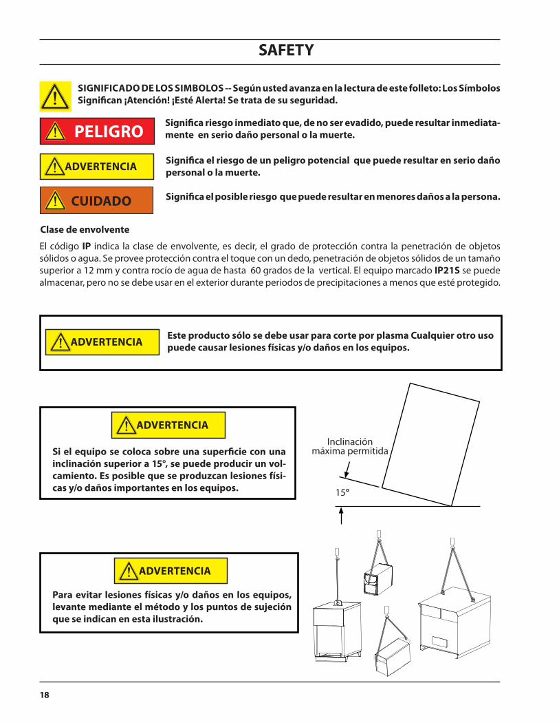
Inclinación máxima permitidasi el equipo se coloca sobre una superficie con una
inclinación superior a 15°, se puede producir un vol-camiento. es posible que se produzcan lesiones físi-cas y/o daños importantes en los equipos.
para evitar lesiones físicas y/o daños en los equipos, levante mediante el método y los puntos de sujeción que se indican en esta ilustración.
significa riesgo inmediato que, de no ser evadido, puede resultar inmediata-mente en serio daño personal o la muerte.
cuiDaDo
peligro
aDVertencia
aDVertencia
aDVertencia
aDVertencia
SAFETY
19
safety - french incenDies et explosions -- la chaleur provenant des flammes ou de l'arc peut provoquer un incendie. le laitier incandescent ou les étincelles peuvent également provoquer un
incendie ou une explosion. par conséquent :
1. Éloignez suffisamment tous les matériaux combustibles de l'aire de travail et recouvrez les matériaux avec un revêtement protecteur ininflammable. Les matériaux combustibles incluent le bois, les vêtements, la sciure, le gaz et les liquides combustibles, les solvants, les peintures et les revêtements, le papier, etc.
2. Les étincelles et les projections de métal incandescent peuvent tomber dans les fissures dans les planchers ou dans les ouvertures des murs et déclencher un incendie couvant à l'étage inférieur Assurez-vous que ces ouver-tures sont bien protégées des étincelles et du métal incandescent.
3. N'exécutez pas de soudure, de coupe ou autre travail à chaud avant d'avoir complètement nettoyé la surface de la pièce à traiter de façon à ce qu'il n'ait aucune substance présente qui pourrait produire des vapeurs inflammables ou toxiques. N'exécutez pas de travail à chaud sur des contenants fermés car ces derniers pourraient exploser.
4. Assurez-vous qu'un équipement d'extinction d'incendie est disponible et prêt à servir, tel qu'un tuyau d'arrosage, un seau d'eau, un seau de sable ou un extincteur portatif. Assurez-vous d'être bien instruit par rapport à l'usage de cet équipement.
5. Assurez-vous de ne pas excéder la capacité de l'équipement. Par exemple, un câble de soudage sur-chargé peut surchauffer et provoquer un incendie.
6. Une fois les opérations terminées, inspectez l'aire de travail pour assurer qu'aucune étincelle ou projection de métal incandescent ne risque de provoquer un incendie ultérieurement. Employez des guetteurs d'incendie au besoin.
7. Pour obtenir des informations supplémentaires, consultez le NFPA Standard 51B, "Fire Prevention in Use of Cutting and Welding Processes", disponible au National Fire Protection Association, Batterymarch Park, Quincy, MA 02269.
choc ÉlectriQue -- le contact avec des pièces élec-triques ou les pièces de mise à la terre sous tension peut causer des blessures graves ou mortelles. ne pas utiliser un courant de soudage c.a. dans un endroit humide, en espace restreint ou si un danger de chute se pose.
aVertissement : ces règles de sécurité ont pour but d'assurer votre protection. ils récapitulent les informations de pré-caution provenant des références dans
la section des informations de sécurité supplémen-taires. avant de procéder à l'installation ou d'utiliser l'unité, assurez-vous de lire et de suivre les précau-tions de sécurité ci-dessous, dans les manuels, les fiches d'information sur la sécurité du matériel et sur les étiquettes, etc. tout défaut d'observer ces précautions de sécurité peut entraîner des blessures graves ou mortelles.
protÉgeZ-Vous -- les processus de soudage, de coupage et de gougeage produisent un niveau de bruit élevé et exige l'emploi d'une protection auditive.
l'arc, tout comme le soleil, émet des rayons ultraviolets en plus d'autre rayons qui peuvent causer des blessures à la peau et les yeux. le métal incandescent peut causer des brûlures. une formation reliée à l'usage des proces-sus et de l'équipement est essentielle pour prévenir les accidents. par conséquent: 1. Portez des lunettes protectrices munies d'écrans latéraux
lorsque vous êtes dans l'aire de travail, même si vous de-vez porter un casque de soudeur, un écran facial ou des lunettes étanches.
2. Portez un écran facial muni de verres filtrants et de plaques protectrices appropriées afin de protéger vos yeux, votre visage, votre cou et vos oreilles des étincelles et des rayons de l'arc lors d'une opération ou lorsque vous observez une opération. Avertissez les personnes se trouvant à proximité de ne pas regarder l'arc et de ne pas s'exposer aux rayons de l'arc électrique ou le métal incandescent.
3. Portez des gants ignifugiés à crispin, une chemise épaisse à manches longues, des pantalons sans rebord et des chaussures montantes afin de vous protéger des rayons de l'arc, des étincelles et du métal incandescent, en plus d'un casque de soudeur ou casquette pour protéger vos cheveux. Il est également recommandé de porter un tablier ininflammable afin de vous protéger des étincelles et de la chaleur par rayonnement.
4. Les étincelles et les projections de métal incandescent risquent de se loger dans les manches retroussées, les rebords de pantalons ou les poches. Il est recommandé de garder boutonnés le col et les manches et de porter des vêtements sans poches en avant.
5. Protégez toute personne se trouvant à proximité des étin-celles et des rayons de l'arc à l'aide d'un rideau ou d'une cloison ininflammable.
6. Portez des lunettes étanches par dessus vos lunettes de sécurité lors des opérations d'écaillage ou de meulage du laitier. Les écailles de laitier incandescent peuvent être projetées à des distances considérables. Les personnes se trouvant à proximité doivent également porter des lunettes étanches par dessus leur lunettes de sécurité.
SAFETY
20
3. Les soudeurs doivent suivre les procédures suivantes pour minimiser l'exposition aux champs électriques et magnétiques :
A. Acheminez l'électrode et les câbles de masse ensemble. Fixez-les à l'aide d'une bande adhésive lorsque possible.
B. Ne jamais enrouler la torche ou le câble de masse autour de votre corps.
C. Ne jamais vous placer entre la torche et les câbles de masse. Acheminez tous les câbles sur le même côté de votre corps.
D. Branchez le câble de masse à la pièce à traiter le plus près possible de la section à souder.
E. Veillez à garder la source d'alimentation pour le soudage et les câbles à une distance appropriée de votre corps.
les Vapeurs et les gaZ -- peuvent causer un malaise ou des dommages corporels, plus particulièrement dans les espaces restreints. ne re-spirez pas les vapeurs et les gaz. le gaz de protection risque de causer l'asphyxie. par conséquent :
1. Assurez en permanence une ventilation adéquate dans l'aire de travail en maintenant une ventila-tion naturelle ou à l'aide de moyens mécanique. N'effectuez jamais de travaux de soudage, de coup-age ou de gougeage sur des matériaux tels que l'acier galvanisé, l'acier inoxydable, le cuivre, le zinc, le plomb, le berylliym ou le cadmium en l'absence de moyens mécaniques de ventilation efficaces. Ne respirez pas les vapeurs de ces matériaux.
2. N'effectuez jamais de travaux à proximité d'une opération de dégraissage ou de pulvérisation. Lorsque la chaleur
ou le rayonnement de l'arc entre en contact avec les vapeurs d'hydrocarbure chloré, ceci peut déclencher la formation de phosgène ou d'autres gaz irritants, tous extrêmement toxiques.
3. Une irritation momentanée des yeux, du nez ou de la gorge au cours d'une opération indique que la ven-tilation n'est pas adéquate. Cessez votre travail afin de prendre les mesures nécessaires pour améliorer la ventilation dans l'aire de travail. Ne poursuivez pas l'opération si le malaise persiste.
4. Consultez ANSI/ASC Standard Z49.1 (à la page suivante) pour des recommandations spécifiques concernant la ventilation.
1. Assurez-vous que le châssis de la source d'alimentation est branché au système de mise à la terre de l'alimentation d'entrée.
2. Branchez la pièce à traiter à une bonne mise de terre électrique.
3. Branchez le câble de masse à la pièce à traiter et assurez une bonne connexion afin d'éviter le risque de choc électrique mortel.
4. Utilisez toujours un équipement correctement entretenu. Remplacez les câbles usés ou endom-magés.
5. Veillez à garder votre environnement sec, incluant les vêtements, l'aire de travail, les câbles, le porte-électrode/torche et la source d'alimentation.
6. Assurez-vous que tout votre corps est bien isolé de la pièce à traiter et des pièces de la mise à la terre.
7. Si vous devez effectuer votre travail dans un espace restreint ou humide, ne tenez vous pas directe-ment sur le métal ou sur la terre; tenez-vous sur des planches sèches ou une plate-forme isolée et portez des chaussures à semelles de caoutchouc.
8. Avant de mettre l'équipement sous tension, isolez vos mains avec des gants secs et sans trous.
9. Mettez l'équipement hors tension avant d'enlever vos gants.
10. Consultez ANSI/ASC Standard Z49.1 (listé à la page suivante) pour des recommandations spécifiques concernant les procédures de mise à la terre. Ne pas confondre le câble de masse avec le câble de mise à la terre.
champs ÉlectriQues et magnÉtiQues — com-portent un risque de danger. le courant électrique qui passe dans n'importe quel conducteur produit des champs électriques et magné-tiques localisés. le soudage et le
courant de coupage créent des champs électriques et magnétiques autour des câbles de soudage et l'équipement. par conséquent :
1. Un soudeur ayant un stimulateur cardiaque doit consulter son médecin avant d'entreprendre une opération de soudage. Les champs électriques et magnétiques peuvent causer des ennuis pour cer-tains stimulateurs cardiaques.
2. L'exposition à des champs électriques et magné-tiques peut avoir des effets néfastes inconnus pour la santé.

SAFETY
21
1. Efforcez-vous de toujours confier les tâches d'installation, de dépannage et d'entretien à un personnel qualifié. N'effectuez aucune réparation électrique à moins d'être qualifié à cet effet.
2. Avant de procéder à une tâche d'entretien à l'intérieur de la source d'alimentation, débranchez l'alimentation électrique.
3. Maintenez les câbles, les fils de mise à la terre, les branchements, le cordon d'alimentation et la source d'alimentation en bon état. N'utilisez jamais un équipe-ment s'il présente une défectuosité quelconque.
4. N'utilisez pas l'équipement de façon abusive. Gardez l'équipement à l'écart de toute source de chaleur, notamment des fours, de l'humidité, des flaques d'eau, de l'huile ou de la graisse, des atmosphères corrosives et des intempéries.
5. Laissez en place tous les dispositifs de sécurité et tous les panneaux de la console et maintenez-les en bon état.
6. Utilisez l'équipement conformément à son usage prévu et n'effectuez aucune modification.
informations supplÉmentaires relatiVes À la sÉcuritÉ -- pour obtenir de l'information supplémentaire sur les règles de sécurité à observer pour l'équipement de soudage à
l'arc électrique et le coupage, demandez un exem-plaire du livret "precautions and safe practices for arc Welding, cutting and gouging", form 52-529.
Les publications suivantes sont également recomman-dées et mises à votre disposition par l'American Weld-ing Society, 550 N.W. LeJuene Road, Miami, FL 33126 :
5. aVertissement : ce produit, lorsqu'il est utilisé dans une opération de soudage ou de coupage, dégage des vapeurs ou des gaz contenant des chimiques considéres par l'état de la californie comme étant une cause des malformations congénitales et dans certains cas, du cancer. (california health & safety code §25249.5 et seq.)
manipulation Des cYlinDres -- la manipulation d'un cylindre, sans observer les précautions nécessaires, peut produire des fissures et un échappement dangereux des gaz.
une brisure soudaine du cylindre, de la soupape ou du dispositif de surpression peut causer des blessures graves ou mortelles. par conséquent :
1. Utilisez toujours le gaz prévu pour une opération et le détendeur approprié conçu pour utilisation sur les cyl-indres de gaz comprimé. N'utilisez jamais d'adaptateur. Maintenez en bon état les tuyaux et les raccords. Observez les instructions d'opération du fabricant pour assembler le détendeur sur un cylindre de gaz comprimé.
2. Fixez les cylindres dans une position verticale, à l'aide d'une chaîne ou une sangle, sur un chariot manuel, un châssis de roulement, un banc, un mur, une colonne ou un support convenable. Ne fixez jamais un cylindre à un poste de travail ou toute autre dispositif faisant partie d'un circuit électrique.
3. Lorsque les cylindres ne servent pas, gardez les soupapes fermées. Si le détendeur n'est pas branché, assurez-vous que le bouchon de protection de la soupape est bien en place. Fixez et déplacez les cylindres à l'aide d'un chariot manuel approprié. Toujours manipuler les cylindres avec soin.
4. Placez les cylindres à une distance appropriée de toute source de chaleur, des étincelles et des flammes. Ne jamais amorcer l'arc sur un cylindre.
5. Pour de l'information supplémentaire, consultez CGA Standard P-1, "Precautions for Safe Handling of Com-pressed Gases in Cylinders", mis à votre disposition par le Compressed Gas Association, 1235 Jefferson Davis Highway, Arlington, VA 22202.
entretien De l'ÉQuipement -- un équipe-ment entretenu de façon défectueuse ou inadéquate peut causer des blessures graves ou mortelles. par conséquent :
1. ANSI/ASC Z49.1 - “Safety in Welding and Cutting”.2. AWS C5.1 - “Recommended Practices for Plasma Arc
Welding”.3. AWS C5.2 - “Recommended Practices for Plasma Arc
Cutting”.4. AWS C5.3 - “Recommended Practices for Air Carbon
Arc Gouging and Cutting”.5. AWS C5.5 - “Recommended Practices for Gas Tung-
sten Arc Welding“.6. AWS C5.6 - “Recommended Practices for Gas Metal
Arc Welding”.7. AWS SP - “Safe Practices” - Reprint, Welding Hand-
book.8. ANSI/AWS F4.1, “Recommended Safe Practices for
Welding and Cutting of Containers That Have Held Hazardous Substances.”
9. CSA Standard - W117.2 = Safety in Welding, Cutting and Allied Processes.
SAFETY
22
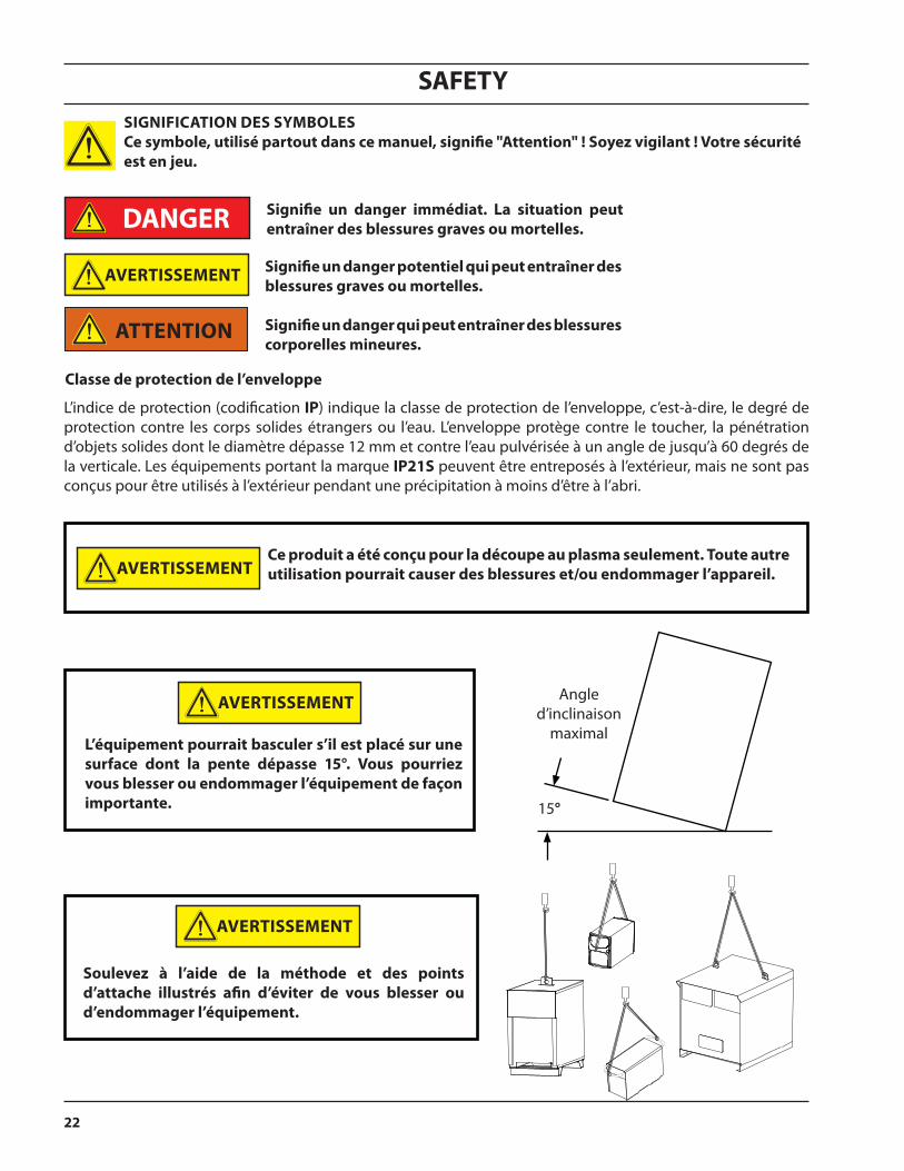
signifie un danger immédiat. la situation peut entraîner des blessures graves ou mortelles.
signifie un danger potentiel qui peut entraîner des blessures graves ou mortelles.
signifie un danger qui peut entraîner des blessures corporelles mineures.
L’indice de protection (codification ip) indique la classe de protection de l’enveloppe, c’est-à-dire, le degré de protection contre les corps solides étrangers ou l’eau. L’enveloppe protège contre le toucher, la pénétration d’objets solides dont le diamètre dépasse 12 mm et contre l’eau pulvérisée à un angle de jusqu’à 60 degrés de la verticale. Les équipements portant la marque ip21s peuvent être entreposés à l’extérieur, mais ne sont pas conçus pour être utilisés à l’extérieur pendant une précipitation à moins d’être à l’abri.
classe de protection de l’enveloppe
ce produit a été conçu pour la découpe au plasma seulement. toute autre utilisation pourrait causer des blessures et/ou endommager l’appareil.
15°
Angle d’inclinaison
maximall’équipement pourrait basculer s’il est placé sur une surface dont la pente dépasse 15°. Vous pourriez vous blesser ou endommager l’équipement de façon importante.
soulevez à l’aide de la méthode et des points d’attache illustrés afin d’éviter de vous blesser ou d’endommager l’équipement.
attention
Danger
aVertissement
signification Des sYmBolesce symbole, utilisé partout dans ce manuel, signifie "attention" ! soyez vigilant ! Votre sécurité est en jeu.
aVertissement
aVertissement
aVertissement

system Diagram

24
SyStem Diagram
aBBreViations:a/c - Air Curtainacc - Air Curtain Controlahc - Automatic Height Control cgc - Combined Gas Controlich - Interface Control Hubigc - Integrated Gas ControlpDB - Power Distribution Boxras - Remote Arc StarterWic - Water Injection Control
Below are some abbreviations used throughout this manual.

25
SyStem Diagram
The following illustration shows configurations available on the Integrated Gas Control (IGC) System. With this system, ESAB offers a variety of configurations to meet customer’s requirements. Below are the descriptions of each configuration.
1. Base system This system is the basic configuration for the IGC Plasma System. It contains major components, such as the Power Supply, PT-36 Torch, Remote Arc Starter (RAS), Combined Gas Control (CGC), Automatic Height Control (AHC) and Vision CNC. This system will meet most customers’ needs in cutting carbon steel, stainless steel, and aluminum. It also has the functionality of marking on carbon steel and stainless steel with the same torch and the same consum-ables. By simply alternating cutting and marking mode on the go, this system is capable of cutting and marking in the same part program without changing the consumables.
2. Base system + acc This system includes the above Base System and ESAB Air Curtain Control (ACC). Air Curtain is a device used to improve the performance of plasma arc when cutting underwater. The Air Curtain output is triggered from the AHC electrical cabinet.
3. Base system + Wic This system is configured to introduce the Water Injection Control (WIC), a module used to regulate cut water flow to shield the cutting process. This configuration is to meet needs of a customer who wants to cut stainless steel without using H35. This system still uses the standard PT-36 torch, but a different set of consumables. Similar to the dry system, this WIC system can also do marking with water shield.
4. Base system + Wic + acc (diagram shows all options) This complete system gives the opportunity for customer to cut carbon steel, stainless steel, and aluminum. Cus-tomer has the capability to cut stainless steel with Water Injection Control (WIC), and underwater with the help of Air Curtain Control (ACC).
system Diagrams

Base
sys
tem
+ W
ic +
acc
(all
opti
ons)
R
Inte
grat
ed G
as C
ontr
ol M
achi
ne V
ersi
on
Inte
rcon
nect
Dia
gram
IG
C B
ase
Sys
tem
(E
PP
-202
/362
) V
isio
n 5X
R
BO
LD F
ON
T =
Cab
le C
onne
ctio
n La
bel
{TH
RE
E
PH
AS
E
PO
WE
R
WIC
-AIR
IN
WIC
-H2O
IN
WIC
-CA
N
WIC
-AC
-IN
PS(P
ower
Sup
ply)
CAN-WIC-CAN
CAN-AHC-CAN
PO
WE
RD
ATA
LIQ
UID
Opt
iona
lG
AS
CN
C-E
ST
OP
Cont
rol B
ox
AH
C-P
WR
PS-W
CG
C-C
AN
CN
C-W
IC P
WR
CN
C-C
AN
P/S
-CA
N
Visio
n CN
C
CAN
Hub
P/S
-CA
N
Wor
k Ta
ble
CG
C-C
AN
AH
C-A
CC
OU
T
Cus
tom
er S
uppl
ied
ACC
(Air
Curta
in C
ontro
l)
WIC
(Wat
er In
ject
ion
Cont
rol)
RAS
(Rem
ote
Arc
Star
ter)
AH
C-A
C I
N
AH
C-C
AN
RA
S-V
DR
AH
C-V
DR
AHC
(Aut
omat
icHe
ight
Co
ntro
l)
Pow
er, P
ilot A
rc, C
oola
nt
PT-
36 T
orch
CG
C-S
G o
r B
PR-S
G/H
2OS
hiel
d G
as H
ose
Pla
sma
Gas
Hos
eC
GC
-PG
Air C
urta
in
Hos
eA
ir C
urta
in
PD
M-P
WR
CG
C-P
WR
CGC
(Com
bine
d G
as C
ontro
l)
BPR
(Bac
k Pr
essu
re
Regu
lato
r)
CG
C-A
IR I
NA
CC
-AIR
OU
T
CG
C-O
2/H
35/F
5
CG
C-N
2/A
ir
CG
C-A
r
CG
C-N
2/A
ir
AC
C-A
IR
AHC
Inpu
t Pow
er
CAN
BU
S
BP
R-H
2O
WIC
-H2O
OU
T
RA
S-E
STO
P
RA
S-P
A
RA
S-E
(-)
RA
S-P
SC
RA
S-T
C I
N
RA
S-T
C O
UT
PS
& C
C C
ontro
l Cab
le
Pow
er C
able
Pilo
t Arc
Cab
le
PS
-PS
C
PS
(-)
PS
-PA
Coo
lant
Sup
ply
Hos
e
Coo
lant
Ret
urn
Hos
e
AC
C-I
N

Descriptions

28
Description

29
Description
power supplies
The IGC system can use different plasma power supplies. ESAB provides the EPP-202/362, with various input voltages and current output for your requirements. For details about our power supplies, please refer to the power supply’s specific manual.
part number
epp-202, 200/230/460V,
60hz, 0558011310
epp-202, 380/400V ccc,
50hz, 0558011311
epp-202,400V ce,
50hz, 0558011312
epp-202, 575V, 60hz,
0558011313
output (100 %
duty cycle)
Voltage 160 VDC
Current range DC (marking) 10A to 36A
Current range DC (cutting) 30A to 200A
Power 32KW
Open Circuit Voltage (OCV) 360 VDC 342/360 VDC 360 VDC 366 VDC
input
Voltage (3-phase) 200/230/460 V 380/400 V 400 V 575 V
Current (3- phase) 115/96/50 A RMS 60/57 A RMS 57 A RMS 43 A RMS
Frequency 60 Hz 50 Hz 50 Hz 60 Hz
KVA 39.5 KVA 39.5 KVA 39.5 KVA 39.5 KVA
Power 35.5 KW 35.5 KW 35.5 KW 35.5 KW
Power Factor 90% 90% 90% 90%
Input Fuse (recommended) 150/125/70 A 80/75 A 75 A 60 A
Weight - lbs (kg) 941 (427) 939 (426) 957 (434) 1085 (492)
380/400V power supplies460/575V power supplies

30
Description
part number
epp-362, 460V, 60hz,
0558011314
epp-362, 380V ccc,
50hz, 0558011315
epp-362,400V ce,
50hz, 0558011316
epp-362, 575V, 60hz,
0558011317
output (100 %
duty cycle)
Voltage 200 VDC
Current range DC (marking) 10A to 36A
Current range DC (cutting) 30A to 360A
Power 72KW
Open Circuit Voltage (OCV) 360 VDC 364 VDC 360 VDC 360 VDC
input
Voltage (3-phase) 460 V 380 V 400 V 575 V
Current (3- phase) 109 A RMS 134 A RMS 128 A RMS 88 A RMS
Frequency 60 Hz 50 Hz 50 Hz 60 Hz
KVA 88.7 KVA 88.5 KVA 88.6 KVA 87.7 KVA
Power 83.7 KW 85.1 KW 84.7 KW 84.0 KW
Power Factor 94% 96% 96% 96%
Input Fuse (recommended) 150 A 175 A 175 A 125 A
Weight - lbs (kg) 1130 (514) 1130 (514) 1140 (518) 1125 (512)
The IGC system can use different plasma power supplies. ESAB provides the EPP-202/362, with various input voltages and current output for your requirements. For details about our power supplies, please refer to the power supply’s specific manual.
380/400V power supplies460/575V power supplies

31
Description
combined gas control (cgc)
There are four gas inputs (three plasma gases, one shield gas), two gas outputs (SG, PG), and one outboard con-nection (air curtain). The four inputs are fitted with porous bronze filters and "G-1/4" (BSPP) female right-hand thread. Either of two adaptor fitting kits are available to adapt standard metric or CGA hose connections. The gas fittings and adaptors are listed in the following tables.
p/n 0558010241
The Combined Gas Control regulates the output of the plasma gas (PG) selected from the three plasma gas inlets (N2/Air, O2/H35 and Argon) and controls the flow of shield gas (SG). It is powered by 24 Volts (AC and DC) from the RAS Box and receives commands via the CAN-bus directly from the CNC.
Like the Shield Gas Box and the Plasma Gas Box, the gas output of the Combined Gas Control is monitored and fed back through the CAN-bus to CNC for self-diagnosis.
specificationsDimensions: 8.5” (215.9 mm) long x 6.0” (152.4 mm) wide x 4.5” (114.3 mm) highWeight: 8.65 lbs. (3.9 kg)power input: 24 VAC/DC
* 8.50” (215.9 mm) including fittings on
front and backnote:CAN cable must be routed separate
from torch leads.
* 6.25”(158.8 mm)
4.75”(120.7 mm)
4.50”(114.3 mm)
32
Description
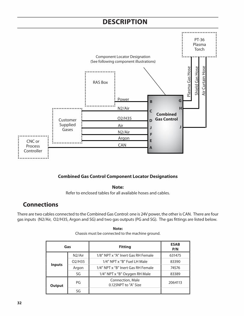
CNC or Process
ControllerCAN
RAS Box
Shie
ld G
as H
ose
Plas
ma
Gas
Hos
e
combinedgas control
Argon
PT-36PlasmaTorch
B g
f
e
D
c
a
h
Component Locator Designation(See following component illustrations)
note:Refer to enclosed tables for all available hoses and cables.
combined gas control component locator Designations
N2/Air
O2/H35
N2/Air
Power
Air
Air
Curt
ain
Hos
e
J
Customer Supplied
GasesJ
connectionsThere are two cables connected to the Combined Gas Control: one is 24V power, the other is CAN. There are four gas inputs (N2/Air, O2/H35, Argon and SG) and two gas outputs (PG and SG). The gas fittings are listed below.
note:Chassis must be connected to the machine ground.
gas fitting esaBp/n
inputs
N2/Air 1/8” NPT x “A” Inert Gas RH Female 631475
O2/H35 1/4” NPT x “B” Fuel LH Male 83390
Argon 1/4” NPT x “B” Inert Gas RH Female 74S76
SG 1/4” NPT x “B” Oxygen RH Male 83389
outputPG Connection, Male
0.125NPT to "A" Size 2064113
SG
33
Description
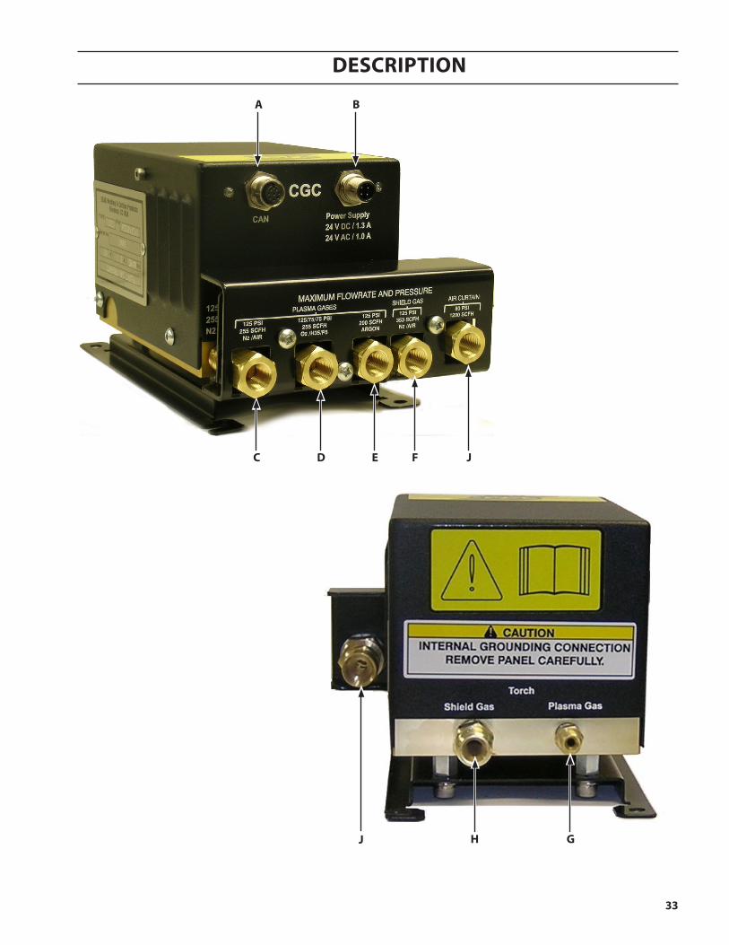
g
Ba
c e fD
h
J
J
34
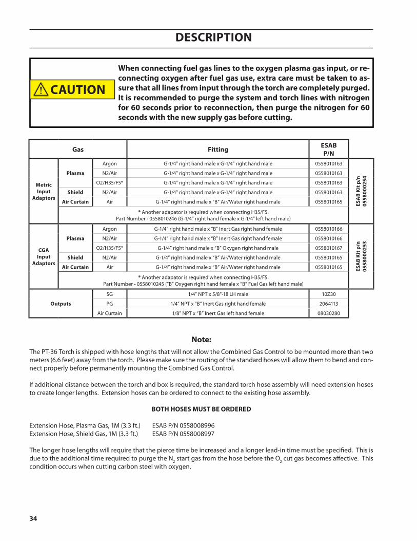
Description
The PT-36 Torch is shipped with hose lengths that will not allow the Combined Gas Control to be mounted more than two meters (6.6 feet) away from the torch. Please make sure the routing of the standard hoses will allow them to bend and con-nect properly before permanently mounting the Combined Gas Control.
If additional distance between the torch and box is required, the standard torch hose assembly will need extension hoses to create longer lengths. Extension hoses can be ordered to connect to the existing hose assembly.
Both hoses must Be orDereD
Extension Hose, Plasma Gas, 1M (3.3 ft.) ESAB P/N 0558008996Extension Hose, Shield Gas, 1M (3.3 ft.) ESAB P/N 0558008997
The longer hose lengths will require that the pierce time be increased and a longer lead-in time must be specified. This is due to the additional time required to purge the N2 start gas from the hose before the O2 cut gas becomes affective. This condition occurs when cutting carbon steel with oxygen.
gas fitting esaBp/n
metric input
adaptors
plasma
Argon G-1/4” right hand male x G-1/4” right hand male 0558010163
esa
B K
it p
/n
0558
0002
54
N2/Air G-1/4” right hand male x G-1/4” right hand male 0558010163
O2/H35/F5* G-1/4” right hand male x G-1/4” right hand male 0558010163
shield N2/Air G-1/4” right hand male x G-1/4” right hand male 0558010163
air curtain Air G-1/4” right hand male x “B” Air/Water right hand male 0558010165
* Another adapator is required when connecting H35/F5. Part Number - 0558010246 (G-1/4” right hand female x G-1/4” left hand male)
cgainput
adaptors
plasma
Argon G-1/4” right hand male x “B” Inert Gas right hand female 0558010166
esa
B K
it p
/n
0558
0002
53
N2/Air G-1/4” right hand male x “B” Inert Gas right hand female 0558010166
O2/H35/F5* G-1/4” right hand male x “B” Oxygen right hand male 0558010167
shield N2/Air G-1/4” right hand male x “B” Air/Water right hand male 0558010165
air curtain Air G-1/4” right hand male x “B” Air/Water right hand male 0558010165
* Another adapator is required when connecting H35/F5. Part Number - 0558010245 (“B” Oxygen right hand female x “B” Fuel Gas left hand male)
outputs
SG 1/4” NPT x 5/8"-18 LH male 10Z30
PG 1/4” NPT x “B” Inert Gas right hand female 2064113
Air Curtain 1/8” NPT x “B” Inert Gas left hand female 08030280
note:
When connecting fuel gas lines to the oxygen plasma gas input, or re-connecting oxygen after fuel gas use, extra care must be taken to as-sure that all lines from input through the torch are completely purged. it is recommended to purge the system and torch lines with nitrogen for 60 seconds prior to reconnection, then purge the nitrogen for 60 seconds with the new supply gas before cutting.
caution
35
Description
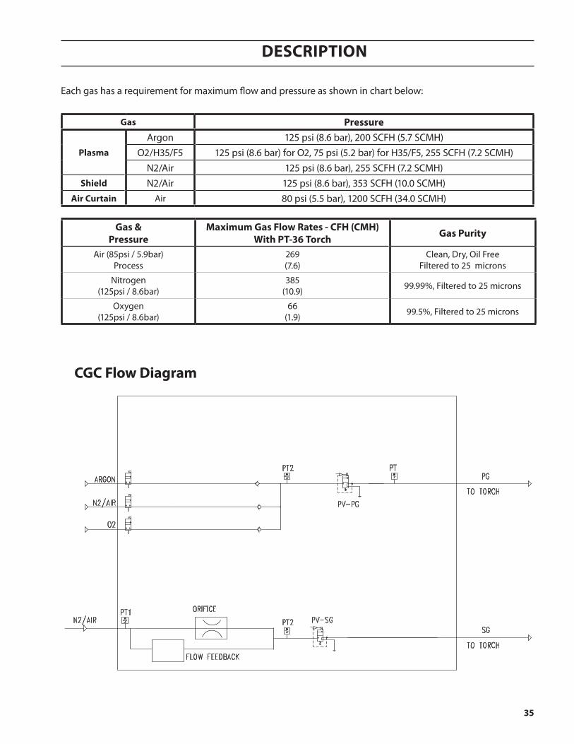
cgc flow Diagram
Each gas has a requirement for maximum flow and pressure as shown in chart below:
gas pressure
plasma
Argon 125 psi (8.6 bar), 200 SCFH (5.7 SCMH)O2/H35/F5 125 psi (8.6 bar) for O2, 75 psi (5.2 bar) for H35/F5, 255 SCFH (7.2 SCMH)
N2/Air 125 psi (8.6 bar), 255 SCFH (7.2 SCMH)shield N2/Air 125 psi (8.6 bar), 353 SCFH (10.0 SCMH)
air curtain Air 80 psi (5.5 bar), 1200 SCFH (34.0 SCMH)
gas &pressure
maximum gas flow rates - cfh (cmh)With pt-36 torch gas purity
Air (85psi / 5.9bar)Process
269(7.6)
Clean, Dry, Oil FreeFiltered to 25 microns
Nitrogen(125psi / 8.6bar)
385(10.9) 99.99%, Filtered to 25 microns
Oxygen(125psi / 8.6bar)
66(1.9) 99.5%, Filtered to 25 microns
36
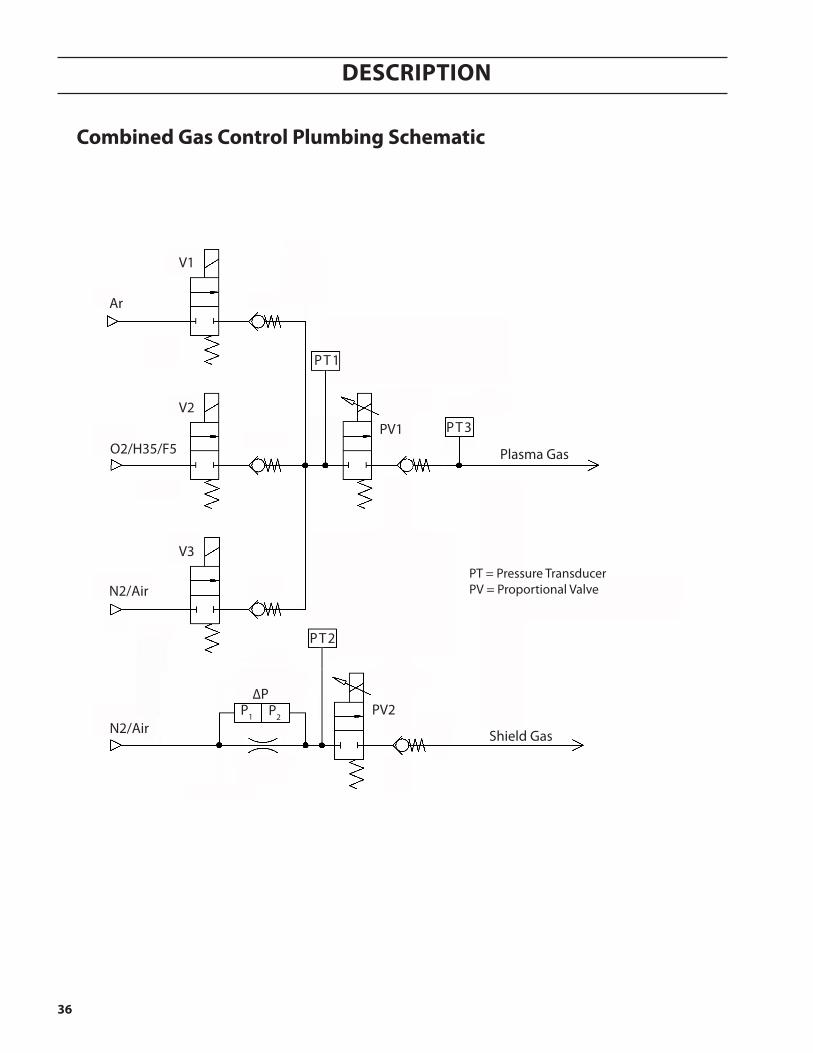
Description
combined gas control plumbing schematic
Plasma Gas
PV1
PV2P1
V1
V2
V3
Ar
O2/H35/F5
N2/Air
PT = Pressure TransducerPV = Proportional Valve
P2
PT3
∆P
PT1
PT2
N2/Air
Shield Gas
37
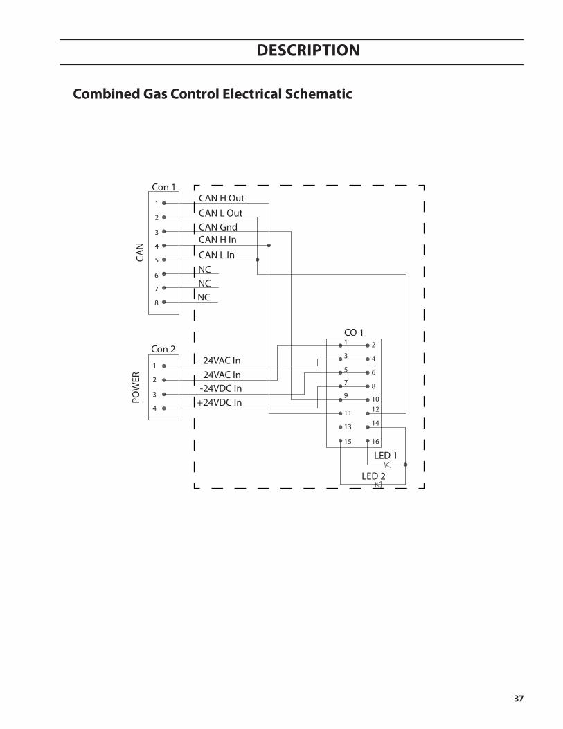
Description
combined gas control electrical schematic
Con 224VAC In24VAC In
-24VDC In+24VDC In
Con 1CAN H OutCAN L OutCAN GndCAN H In
CAN L In
LED 1
LED 2
CO 1
CAN
POW
ER
1 2
15 16
13 1411 12
9 10
7 8
5 6
3 4
1
5
4
3
2
1
4
3
2
NCNCNC
8
7
6
38
Description
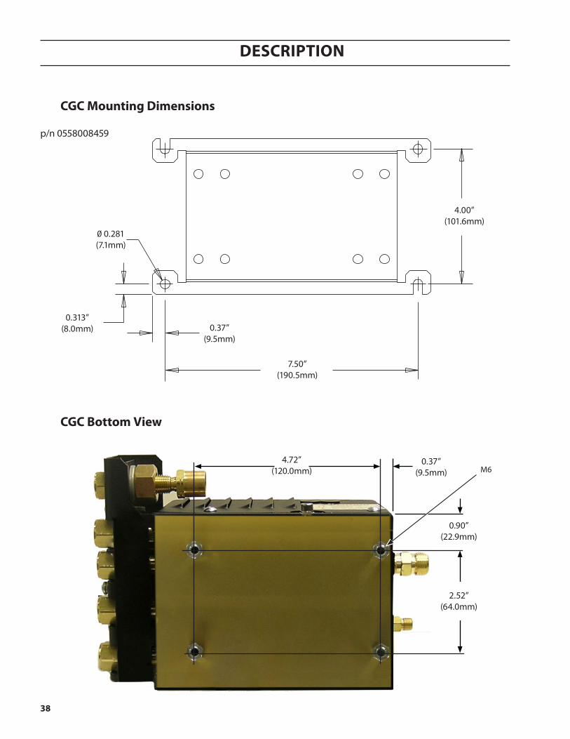
cgc mounting Dimensions
7.50”(190.5mm)
4.00”(101.6mm)
0.37”(9.5mm)
0.313”(8.0mm)
0.281(7.1mm)
p/n 0558008459
cgc Bottom View
2.52”(64.0mm)
4.72”(120.0mm)
0.90”(22.9mm)
0.37”(9.5mm) M6
39
Description
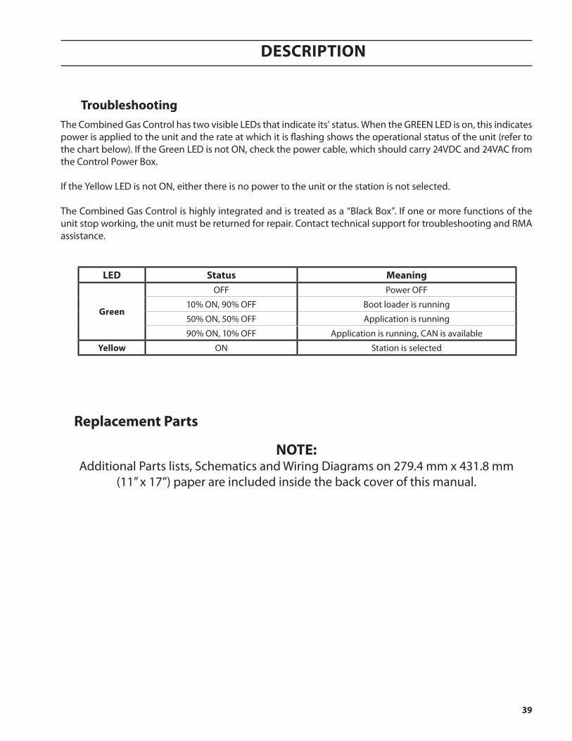
troubleshootingThe Combined Gas Control has two visible LEDs that indicate its’ status. When the GREEN LED is on, this indicates power is applied to the unit and the rate at which it is flashing shows the operational status of the unit (refer to the chart below). If the Green LED is not ON, check the power cable, which should carry 24VDC and 24VAC from the Control Power Box.
If the Yellow LED is not ON, either there is no power to the unit or the station is not selected.
The Combined Gas Control is highly integrated and is treated as a “Black Box”. If one or more functions of the unit stop working, the unit must be returned for repair. Contact technical support for troubleshooting and RMA assistance.
leD status meaning
green
OFF Power OFF
10% ON, 90% OFF Boot loader is running
50% ON, 50% OFF Application is running
90% ON, 10% OFF Application is running, CAN is available
Yellow ON Station is selected
replacement parts
note:Additional Parts lists, Schematics and Wiring Diagrams on 279.4 mm x 431.8 mm
(11” x 17”) paper are included inside the back cover of this manual.
40
Description
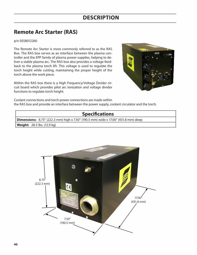
remote arc starter (ras)
The Remote Arc Starter is more commonly referred to as the RAS Box. The RAS box serves as an interface between the plasma con-troller and the EPP family of plasma power supplies, helping to de-liver a stable plasma arc. The RAS box also provides a voltage feed-back to the plasma torch lift. This voltage is used to regulate the torch height while cutting, maintaining the proper height of the torch above the work piece.
Within the RAS box there is a High Frequency/Voltage Divider cir-cuit board which provides pilot arc ionization and voltage divider functions to regulate torch height.
Coolant connections and torch power connections are made within the RAS box and provide an interface between the power supply, coolant circulator and the torch.
specificationsDimensions: 8.75” (222.3 mm) high x 7.50” (190.5 mm) wide x 17.00” (431.8 mm) deepWeight: 28.5 lbs. (12.9 kg)
p/n 0558012260
17.00”(431.8 mm)
7.50”(190.5 mm)
8.75”(222.3 mm)

41
Description
note:Chassis must be connected to the
machine ground.
remote arc starter connections
ef
a
g, h
J
i
letter DescriptionA 3 Pin Voltage Divider Connection to the Lift
C 14 Pin Amphenol Power Supply Connection
D Power Supply Enable
E Coolant Inlet - Flowing to the Torch
F Coolant Return - Flowing back to the Coolant Circu-lator from the Torch
G, H Strain Relief Fittings
I Torch Shroud Connection
J Machine Ground Connection
c
D

42
Description
PowerSupply
PS & CC Control Cable
Power Cable
Pilot Arc Cable
Coolant Supply Hose
Coolant Return Hose
Power Supply Enable
arcstarter
assembly
Power, Pilot Arc, Coolant
VDR Cable
AHC / Lift( Optional ) PT-36
PlasmaTorch
c
D
f
e
h
ga
i
Component Locator Designation(See following component illustrations)
note: Refer to enclosed tables for all available hoses and cables.
remote arc starter Box component locator Designations
Control Box
43
Description
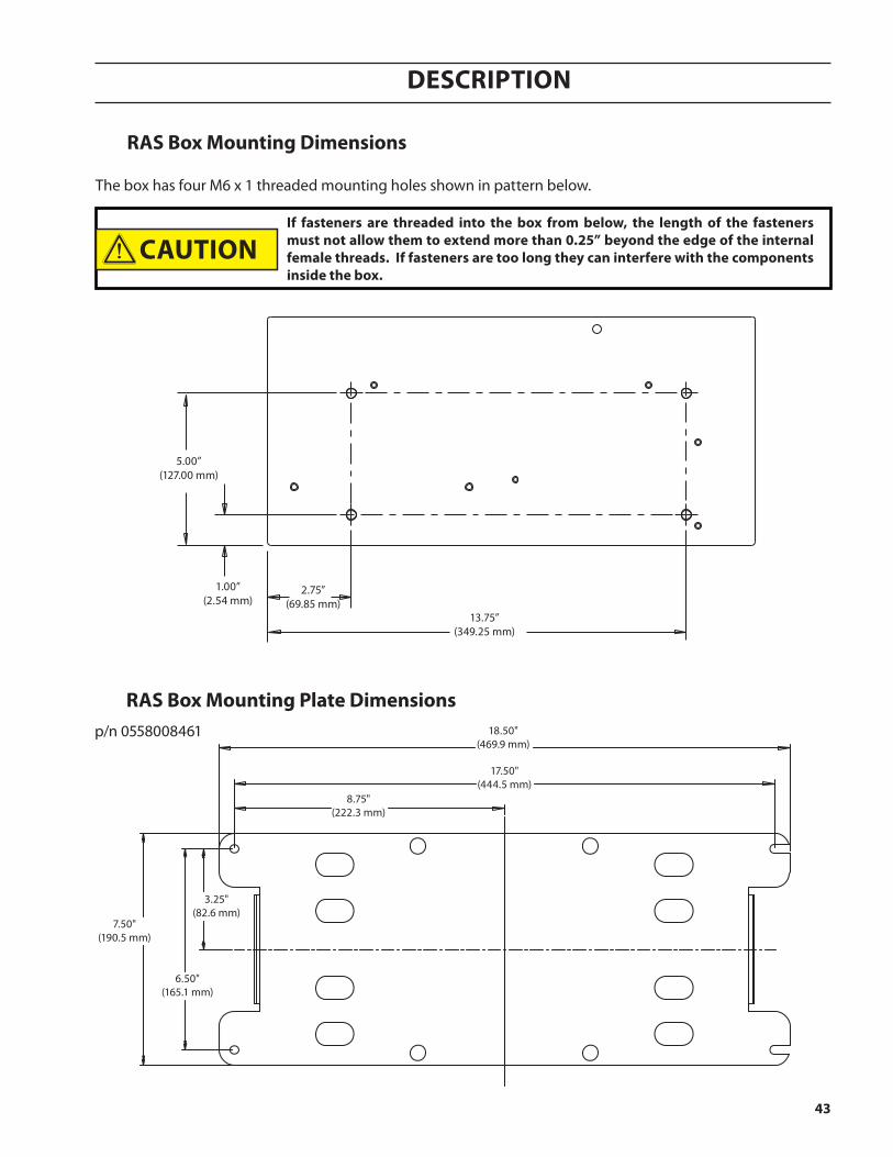
ras Box mounting Dimensions
The box has four M6 x 1 threaded mounting holes shown in pattern below.
5.00”(127.00 mm)
13.75”(349.25 mm)
2.75”(69.85 mm)
1.00” (2.54 mm)
if fasteners are threaded into the box from below, the length of the fasteners must not allow them to extend more than 0.25” beyond the edge of the internal female threads. if fasteners are too long they can interfere with the components inside the box.
18.50"(469.9 mm)
17.50"(444.5 mm)
8.75"(222.3 mm)
7.50"(190.5 mm)
3.25"(82.6 mm)
6.50"(165.1 mm)
caution
ras Box mounting plate Dimensionsp/n 0558008461
44
Description
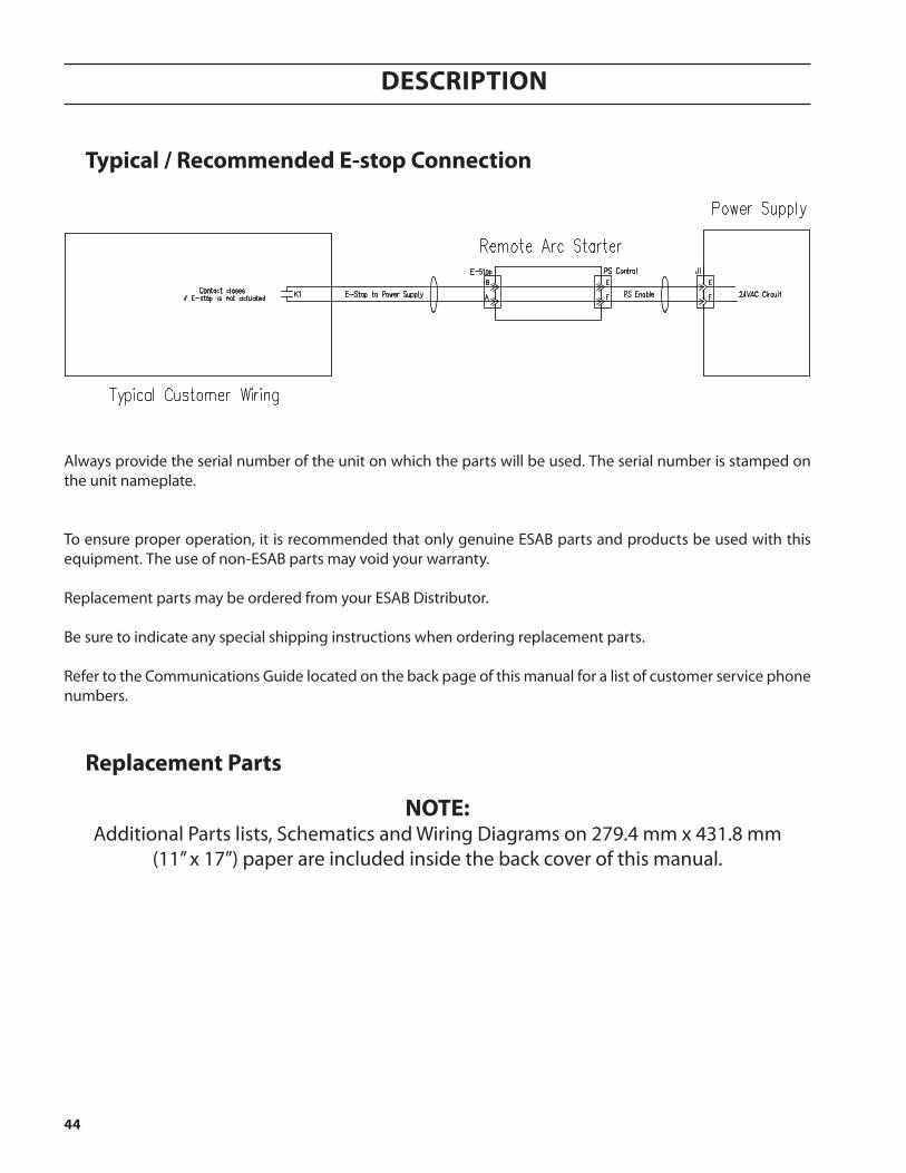
typical / recommended e-stop connection
Always provide the serial number of the unit on which the parts will be used. The serial number is stamped on the unit nameplate.
To ensure proper operation, it is recommended that only genuine ESAB parts and products be used with this equipment. The use of non-ESAB parts may void your warranty.
Replacement parts may be ordered from your ESAB Distributor.
Be sure to indicate any special shipping instructions when ordering replacement parts.
Refer to the Communications Guide located on the back page of this manual for a list of customer service phone numbers.
replacement parts
note:Additional Parts lists, Schematics and Wiring Diagrams on 279.4 mm x 431.8 mm
(11” x 17”) paper are included inside the back cover of this manual.

45
Description
air curtain control (acc)
The Air Curtain is a device used to improve the performance of plasma arc when cutting underwater. The device mounts onto the torch and produces a curtain of air. This allows the plasma arc to operate in a relatively dry zone to reduce noise, fume, and arc radiation, even though the torch has been submerged.
The Air Curtain requires a source of compressed air that needs to be clean, dry and oil-free. It should be delivered at 80 psi @ 1200 cfh (5.5 bar @ 34 CMH).
specificationsDimensions: 6.00” high (152.4 mm) x 9.56” wide (242.8 mm) x 2.50” deep (63.5 mm)Weight: 4.00 lbs. (1.81 kg)input power: 24 VAC
p/n 0558010243p/n 37440

46
Description
acc mounting Dimensions
acc component connections
A
B
9.31”(236.5 mm)
1.16”(29.5 mm) 7.00”
(177.8 mm)
.312” x .500” slots
5.81”(147.6 mm)
2.91”(74.0 mm)
Compressed Air
note:Cables “A” and “B” are listed in the ACC Component Connections, INSTALLATION
section of this manual.

47
Description
Water injection control (Wic)
The Water Injection Control (WIC) regulates the flow of cut water supplied to the plasma torch. This water is used as a shield in the cutting process. This shield assists in forming the plasma arc and also cools the cut surface. The selection and output of cut water is performed and controlled by the ICH. The WIC consists of a water regulator, pump and a closed feedback loop between proportional valve and flow sensor. This is controlled by a local Process Control Unit (PCU). The PCU communicates via CAN to the ICH while controlling the proportional and solenoid valves. The WIC is monitored and sends feedback signals through the CAN bus to the ICH for diagnostic purposes.
For more detailed information on the Water Injection Control (WIC), see manual #0558009491.
specificationsDimensions (electrical module) 163 mm x 307 mm x 163 mm (6.4 in x 12.1 in x 6.4 in)
Dimensions (pump module) 465 mm x 465 mm x 218 mm (18.3 in x 18.3 in x 8.6 in)
Weight (electrical module) 15 lb. dry (6.8 kg)
Weight (pump module) 60 lb. dry (27.2 kg)
Water requirementsTap water with an allowable water hardness of <2 ppm as CaCO3 and Conductivity: >200,000 ohms per inch, filtered at 5 microns. 1 gpm (3.8 l/min) minimum flow rate @ 20 psi (1.4 bar).
air supply (anti-freezing function) 250 CFH @ 80 psi (7.1 cmh @ 5.5 bar)
pump Positive displacement, rotary vane with adjustable by-pass valve (250 psi / 17.2 bars maxi-mum), CW rotation, Capacity: 1.33 GPM @ 150 psi (5.04 l/min @ 10.3 bar), Nominal speed: 1725 rpm, Temperature rating: 150o F (66o C)
motor 1/2 HP, 230 VAC single phase, 60 Hz, 1725 RPM, 3.6A current, Temperature rating: 150o F (66o C)
pressure regulator Inlet water pressure: 100 psi (6.9 bar) maximum Outlet water pressure: 20 psi (1.4 bar) factory set
pressure transducer
Maximum pressure range: 0 - 200 psi (0 - 13.8 bar)Temperature range: -40o - 257o F (-40o - 125o C) Supply voltage: 24 VDC Pressure signal output: 4 mA for 0 psi, 20 mA for 200 psi (13.8 bar). Regulated to 1 to 5 VDC with 250 ohm resistor.
proportional Valve
Supply voltage: 24 VDC Full load current: 500 mA, Input control signal: 0-10 VDC. Coil: Standard Voltage: 24 VDC, Operating current: 100-500 mA, Valve: Orifice size: 3/32”, Cv:0.14 (fully open) Operating differential pressure: 115 psi (8.0 bar) ; Max. flow 1.5 gpm Maximum fluid temperature: 150o F (66o C)
flow sensorMaximum operating pressure: 200 psi (13.8 bar), Operating temperature: -4o - 212o F (-20o - 100o C), Input power: 5 - 24 VDC @ 50 mA maxi-mum, Output signal: 58 - 575 Hz, Flow range: 0.13 - 1.3 gpm
air solenoid Supply voltage: 24 VDC, Maximum operating pressure: 140 psi (9.7 bar) , Operating tem-perature: 32o - 77o F (0 - 25o C)
p/n 0558009370

48
Description
automatic height control (ahc)
The B4 lift assembly provides vertical motion for the PT-36 plasma torch, using a typi-cal motor, screw, and slide configuration. The motor turns an enclosed spindle screw, which in turn raises/lowers the lifting plate along linear rails. Directional commands given from the plasma controller determine the direction of the travel. Fixed limit switches are included to prevent upper and lower lift’s over travel.
The lift assembly also contains components necessary to control height over work surfaces; initial, piercing, and cutting heights are encoder controlled during the plas-ma cycle. During part production, height is automatically controlled by taking volt-age measurements between the torch electrode and work surface.
The B4 lifts utilize an Omni Soft Touch® assembly to protect the system during sta-tion crashes. Proximity switches monitor torch position in the torch holder. If the torch is jarred in any direction, the process will stop and an error report will be sent to the controller.
specificationsDimensions:
6.0” (152.4 mm) wide x 8.5” (215.9 mm) deep x 31.5” (800.1 mm) highlift speed: 315 IPM [8.0m per minute]Vertical travel: 8.00” [200.0 mm]approximate Weight including torch holder: 85 lbs. [38.5 kg]torch Barrel size: 85.7 mm
component tolerancesIHS Accuracy: ± 0.5 mmEncoder Accuracy: ± 0.25 mmVoltage Accuracy: ± 1 volt
p/n 0560947166
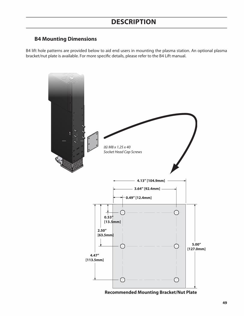
49
Description
B4 lift hole patterns are provided below to aid end users in mounting the plasma station. An optional plasma bracket/nut plate is available. For more specific details, please refer to the B4 Lift manual.
recommended mounting Bracket/nut plate
(6) M8 x 1.25 x 40 Socket Head Cap Screws
5.00”[127.0mm]
4.13” [104.9mm]
0.49” [12.4mm]
3.64” [92.4mm]
4.47”[113.5mm]
x6 M8x1.25 - 6HTHRU HOLES
0.53”[13.5mm]
2.50”[63.5mm]
B4 mounting Dimensions

50
Description
hoses and cables
cable / hoseDescription
availablelengthsm ( ft. )
esaBpart number
CAN Bus Cable
1m (3.3’) 0558008464
2m (6.5’) 0558008465
3m (10’) 0558008466
4m (13’) 0558008467
5m (16’) 0558008468
6m (19’) 0558008469
7m (23’) 0558008470
8m (26’) 0558008471
9m (30’) 0558008472
10m (33’) 0558008473
11m (36’) 0558008474
12m (39’) 0558008475
13m (43’) 0558008476
14m (46’) 0558008477
15m (49’) 0558008478
20m (66’) 0558008479
25m (82') 0558008809
36m (118') 0558008480
30m (100') 0558008481
40m (131') 0558008482
45m (150') 0558008483
50m (164') 0558008484
55m (180') 0558008485
60m (200') 0558008486
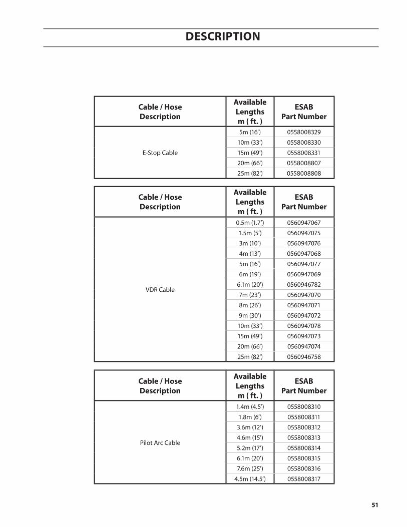
51
Description
cable / hoseDescription
availablelengthsm ( ft. )
esaBpart number
Pilot Arc Cable
1.4m (4.5’) 0558008310
1.8m (6’) 0558008311
3.6m (12’) 0558008312
4.6m (15’) 0558008313
5.2m (17’) 0558008314
6.1m (20’) 0558008315
7.6m (25’) 0558008316
4.5m (14.5’) 0558008317
cable / hoseDescription
availablelengthsm ( ft. )
esaBpart number
E-Stop Cable
5m (16’) 0558008329
10m (33’) 0558008330
15m (49’) 0558008331
20m (66') 0558008807
25m (82') 0558008808
cable / hoseDescription
availablelengthsm ( ft. )
esaBpart number
VDR Cable
0.5m (1.7’) 0560947067
1.5m (5’) 0560947075
3m (10’) 0560947076
4m (13’) 0560947068
5m (16’) 0560947077
6m (19’) 0560947069
6.1m (20') 0560946782
7m (23’) 0560947070
8m (26’) 0560947071
9m (30’) 0560947072
10m (33’) 0560947078
15m (49’) 0560947073
20m (66’) 0560947074
25m (82') 0560946758

52
Description
cable / hoseDescription
availablelengthsm ( ft. )
esaBpart number
Coolant Hose
10m (33') 0558005563
15m (49') 0558005564
20m (66') 0558005565
45m (115') 0558005566
50m (164') 0558005567
5m (16') 0558005246
30m (98') 0558005247
40m (131') 0558005248
77m (196') 0558005249
32m (82') 0558006629
59m (150') 0558006630
71m (180') 0558006631
cable / hoseDescription
availablelengthsm ( ft. )
esaBpart number
Air Curtain Hose2.3m (7.5’) 0558010204
3.4m (11’) 0558010206
plasma gas control to air curtain hoses
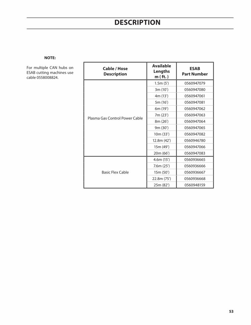
53
Description
note:
For multiple CAN hubs on ESAB cutting machines use cable 0558008824.
cable / hoseDescription
availablelengthsm ( ft. )
esaBpart number
Plasma Gas Control Power Cable
1.5m (5’) 0560947079
3m (10’) 0560947080
4m (13’) 0560947061
5m (16’) 0560947081
6m (19’) 0560947062
7m (23’) 0560947063
8m (26’) 0560947064
9m (30’) 0560947065
10m (33’) 0560947082
12.8m (42') 0560946780
15m (49’) 0560947066
20m (66’) 0560947083
Basic Flex Cable
4.6m (15’) 0560936665
7.6m (25’) 0560936666
15m (50’) 0560936667
22.8m (75’) 0560936668
25m (82’) 0560948159

54
Description
torchDescription
availablelengthsm ( ft. )
esaBpart number
PT-36 m3 CANPlasma Torch
1.4m (4.5’) 0558008301
1.8m (6’) 0558008302
3.6m (12’) 0558008303
4.3m (14’) 0558008308
4.6m (15’) 0558008304
5.2m (17’) 0558008305
6.1m (20’) 0558008306
7.6m (25’) 0558008307
cable / hoseDescription
availablelengthsm ( ft. )
esaBpart number
PS & CC Control CableCable, Control (14PX-14S), Family
0558011630
2.9m (9.5’) 0558011840
7.6m (25’) 0558011631
10m (33’) 0558011632
15m (50’) 0558011633
20m (66’) 0558011634
23m (75’) 0558011635
25m (82’) 0558011636
30m (100’) 0558011637
35m (115’) 0558011963
40m (131’) 0558011638
45m (150’) 0558011964
50m (164’) 0558011639
55m (180’) 0558011965
60m (200’) 0558011640

55
Description
pt-36 mechanized plasmarc cutting torch
specificationstYpe: WATER COOLED, DUAL GAS, MECHANIZED PLASMARC CUTTING TORCH
current rating: 1000 AMPS @ 100% DUTY CYCLE
mounting Diameter: 2 “(50.8 MM)
length of torch Without leaDs: 16.7 “(42 CM)
iec 60974-7 Voltage rating: 500 VOLTS PEAK
striKing Voltage (maximum Value of hi-freQuencY Voltage): 8000 VAC
minimum coolant floWrate: 1.3 GPM (5.9 L/MIN)
minimum coolant pressure at inlet: 175 PSIG (12.1 BAR)
maximum coolant pressure at inlet: 200 PSIG (13.8 BAR)
minimum acceptaBle rating of coolant recirculator: 16,830 BTU/HR (4.9 KW) AT HIGH COOLANT TEMPERATURE - AMBIENT = 45°F (25°C) AND 1.6 USGPM (6 L/MIN)
maximum safe gas pressures at inlets to torch: 125 PSIG (8.6 BAR)
safetY interlocKs: THIS TORCH IS INTENDED FOR USE WITH ESAB PLASMARC CUTTING SYSTEMS AND CONTROLS EMPLOYING A WATER FLOW SWITCH ON THE COOLANT RETURN LINE FROM THE TORCH. REMOVAL OF THE NOZZLE RETAINING CUP TO SERVICE THE TORCH BREAKS THE COOLANT RETURN PATH.
p/n 0558008300
The purpose of this section is to provide the operator with all the information required to install and service the PT-36 Mech-anized Plasmarc Cutting Torch. Technical reference material is also provided to assist in troubleshooting the cutting package.
The PT-36 Mechanized Plasmarc Cutting Torch is a plasma arc torch factory assembled to provide torch component concen-tricity and consistent cutting accuracy. For this reason, the torch body can not be rebuilt in the field. Only the torch front-end has replaceable parts.

56
Description
2.00"(50.8 mm)
7.54"(191.5 mm)
6.17"(156.7 mm)
10.50" (266.7 mm)Length of Sleeve
9.13"(231.9 mm)
package options available
PT-36 package options available through your ESAB dealer. See Replacement Parts section for component part numbers.
optional accessories
Bubble muffler - When used in conjunction with a water pump recirculating water from the table and by using compressed air, this device creates a bubble of air which enables a PT-36 Plasmarc Cutting Torch to be used underwater with less sacrifice of cut quality. This system also permits operation above water as the flow of water through the muffler reduces fume, noise, and arc U.V. Radiation.(for installation/operation instructions see manual 0558006722).............................. 37439
air curtain - This device when supplied with compressed air is used to improve the performance of the PT-36 Plasmarc Cutting Torch when cutting underwater. The de-vice mounts onto the torch and produces a curtain of air. This allows the plasma arc to operate in a relatively dry zone, even though the torch has been submerged to reduce noise, fume, and arc radiation. to be used in underwater applications only.(for installation/operation instructions see manual 0558006404) .............................37440

57
Description
Speedloader assembly, handheld ...............................................................0558006164
Speedloader assembly, 5 fixtures ................................................................0558006165
pt-36 torch consumable Kits
note:Cannot be used with vent hole nozzles.
pt-36 repair & accessories Kit ...................................................................................0558005221
part number Quantity Description
0558003804 1 Torch Body PT-36 w/O-rings
0004485648 10 O-ring 1.614 ID x .070
0558002533 2 Baffle, 4 Hole x .032
0558001625 2 Baffle, 8 Hole x .047
0558002534 1 Baffle, 4 x .032 Reverse
0558002530 1 Baffle, 8 x .047 Reverse
0558005457 1 Baffle, 4 Hole x .022
0558003924 3 Electrode Holder PT-36 w/O-ring
0004485671 10 O-ring .364 ID x .070
0004470045 2 Nozzle Retaining Cup, Standard
0004470030 1 Shield Gas Diffuser, Low Current
0004470031 5 Shield Gas Diffuser, Standard
0004470115 1 Shield Gas Diffuser, Reverse
0004470046 2 Shield Retainer, Standard
0558003858 2 Contact Ring w/screw
0004470044 6 Screw, Contact Ring
0004470049 2 Hex Key Wrench .109"
0558007105 1 Nut Driver 7/16" (Electrode tool)
0558003918 1 Electrode Holder Tool PT-36
0004470869 1 Silicon Grease DC-111 5.3oz

58
Description
pt-36 start-up Kits ..............................................................................................................................
0558010625 600 amp
0558010624 450 amp
0558010623 360 amp
0558010622 200 amp part no Description
5 5 5 5 0558009400 ELECTRODE MICRO PT-36
5 5 5 5 0558003914 ELECTRODE O2 ULTRALIFE, Standard PT-36
5 - - - 0558003928 ELECTRODE N2/H35, Standard PT-36
5 5 5 5 0558009406 NOZZLE 0.6mm (.024") MICRO PT-36
5 5 5 5 0558009411 NOZZLE 1.1mm (.043") MICRO PT-36
5 5 5 5 0558006018 NOZZLE 1.8mm (.070") PT-36
5 5 5 5 0558006020 NOZZLE 2.0mm (.080") PT-36
5 5 5 - 0558006030 NOZZLE 3.0mm (.120") PT-36
5 5 - - 0558006028 NOZZLE 2.8mm (.109") Divergent (O2) PT-36
5 - - - 0558006041 NOZZLE 4.1mm (.161") PT-36
1 1 - - 0558009550 NOZZLE RETAINING CUP HD PT-36
5 5 5 5 0558009425 SHIELD 2.5mm (.099") MICRO PT-36
5 5 5 5 0558006141 SHIELD 4.1mm (.160") PT-36
5 5 5 - 0558006166 SHIELD 6.6mm (.259") PT-36
5 5 - - 0558009551 SHIELD 5.1mm (.200") HD PT-36
5 - - - 0558006199 SHIELD 9.9mm (.390") PT-36
1 1 - - 0558009548 SHIELD RETAINER HD PT-36
5 5 5 5 181W89 O-RING 1.114 ID x .070 CR
1 1 1 1 950561 TOOL BOX
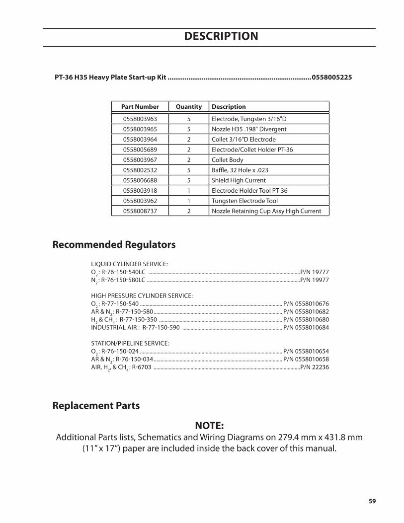
59
Description
replacement parts
note:Additional Parts lists, Schematics and Wiring Diagrams on 279.4 mm x 431.8 mm
(11” x 17”) paper are included inside the back cover of this manual.
recommended regulators
LIQUID CYLINDER SERVICE:O2 : R-76-150-540LC ...............................................................................................................P/N 19777N2 : R-76-150-580LC ................................................................................................................P/N 19977
HIGH PRESSURE CYLINDER SERVICE: O2 : R-77-150-540 ........................................................................................................ P/N 0558010676AR & N2 : R-77-150-580 .............................................................................................. P/N 0558010682H2 & CH4 : R-77-150-350 .......................................................................................... P/N 0558010680INDUSTRIAL AIR : R-77-150-590 ......................................................................... P/N 0558010684
STATION/PIPELINE SERVICE:O2 : R-76-150-024 ........................................................................................................ P/N 0558010654AR & N2 : R-76-150-034 .............................................................................................. P/N 0558010658AIR, H2, & CH4 : R-6703 ...........................................................................................................P/N 22236
part number Quantity Description
0558003963 5 Electrode, Tungsten 3/16"D
0558003965 5 Nozzle H35 .198" Divergent
0558003964 2 Collet 3/16"D Electrode
0558005689 2 Electrode/Collet Holder PT-36
0558003967 2 Collet Body
0558002532 5 Baffle, 32 Hole x .023
0558006688 5 Shield High Current
0558003918 1 Electrode Holder Tool PT-36
0558003962 1 Tungsten Electrode Tool
0558008737 2 Nozzle Retaining Cup Assy High Current
pt-36 h35 heavy plate start-up Kit ............................................................................0558005225

60
Description

installation

InstallatIon
62

InstallatIon
63
installation
Warningfailure to folloW instructions coulD leaD to Death, in-JurY or DamageD propertY. folloW these instructions to preVent inJurY or propertY Damage. You must complY With local, state anD national electrical anD safetY coDes.
check upon receipt
1. Verify all the system components on your order have been received.2. Inspect the system components for any physical damage that may have occurred during shipping. If there
is evidence of damage, please contact your supplier with the model number and serial number from the nameplate.
Before installation
Warningall installation anD serVice of the electrical anD plumB-ing sYstems must conform to national anD local elec-trical anD plumBing coDes. installation shoulD Be per-formeD onlY BY QualifieD, licenseD personnel. consult Your local authorities for anY regulation issues.
general
unpacking• Inspect for transit damage immediately upon receipt.• Remove all components from shipping container and check for loose parts in container.• Inspect louvers for air obstructions.
Locate the major components to the right position prior to making electrical, gas, and interface connections. Refer to the system interconnection diagrams for major components placement. Ground all major components to earth at one point. To prevent leaks, make sure to tighten all gas and water connections with specific torque.
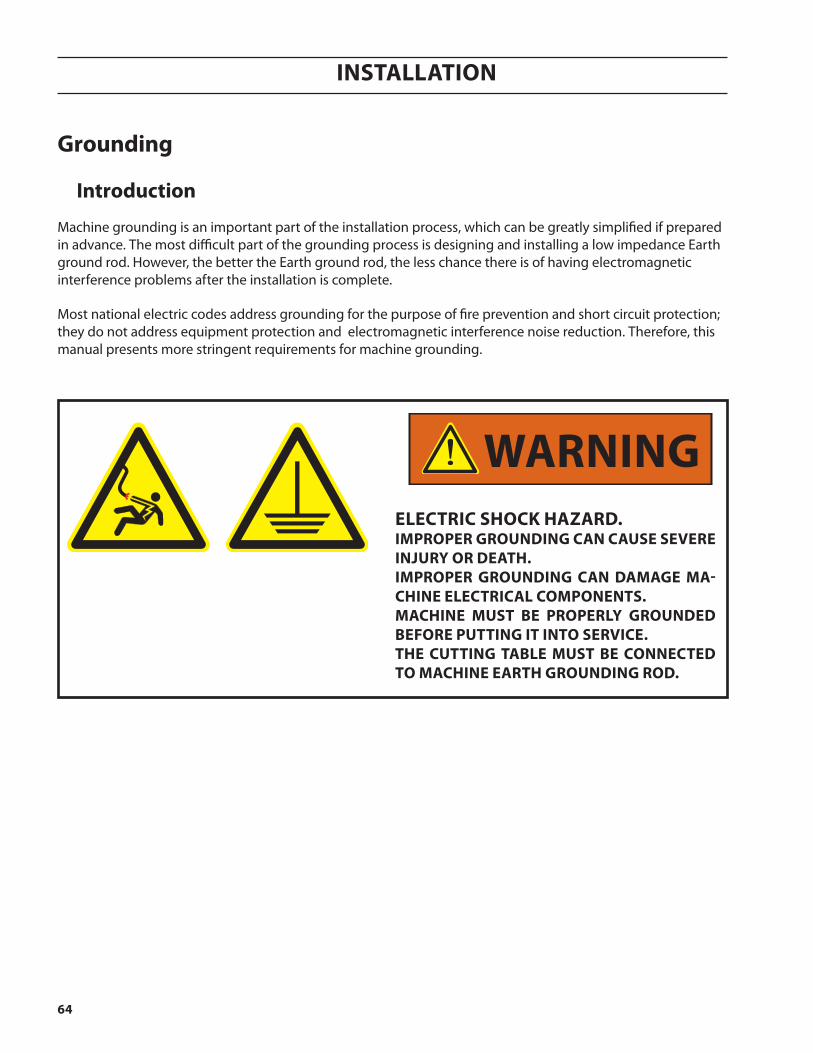
InstallatIon
64
grounding
introduction
Machine grounding is an important part of the installation process, which can be greatly simplified if prepared in advance. The most difficult part of the grounding process is designing and installing a low impedance Earth ground rod. However, the better the Earth ground rod, the less chance there is of having electromagnetic interference problems after the installation is complete.
Most national electric codes address grounding for the purpose of fire prevention and short circuit protection; they do not address equipment protection and electromagnetic interference noise reduction. Therefore, this manual presents more stringent requirements for machine grounding.
Warningelectric shocK haZarD.improper grounDing can cause seVere inJurY or Death.improper grounDing can Damage ma-chine electrical components.machine must Be properlY grounDeD Before putting it into serVice.the cutting taBle must Be connecteD to machine earth grounDing roD.

InstallatIon
65
grounding overview
There are three parts to a ground system;
• Component or "chassis" ground• Earth ground• Protective Earth ground
Component grounding connects all pieces to a single component, like the machine chassis, which is then connected to a common point known as the star point. This provides a path for electromagnetic interference (EMI) from the enclosure to ground.
An earth ground provides a electromagnetic interference (EMI) to return to its source.
A protective earth (PE) ground provides a safe path for fault current. Without a properly grounded system, an unintended path through people or sensitive equipment may be found, resulting in serious injury, death, and/or premature equipment failure.
This section focuses on machines with a plasma cutting system. Machines with plasma cutting capability are particularly prone to electromagnetic interference problems and often utilize dangerous voltages and currents. All machines must have electrical components grounded and attached to an earth ground, regardless of process type (shape cutting, marking, or other material preparation).
A common symbol used to identify an earth ground on drawings.
A common symbol used to identify a chassis ground on drawings.
A common symbol used to identify a protective earth (PE) ground.
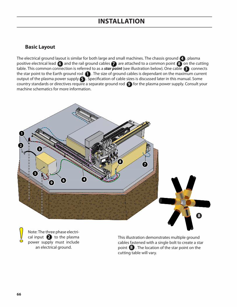
InstallatIon
66
Note: The three phase electri-cal input to the plasma power supply must include
an electrical ground.
Basic layout
This illustration demonstrates multiple ground cables fastened with a single bolt to create a star point . The location of the star point on the cutting table will vary.
8
2
The electrical ground layout is similar for both large and small machines. The chassis ground , plasma positive electrical lead and the rail ground cables are attached to a common point on the cutting table. This common connection is referred to as a star point (see illustration below). One cable connects the star point to the Earth ground rod . The size of ground cables is dependant on the maximum current output of the plasma power supply . Specification of cable sizes is discussed later in this manual. Some country standards or directives require a separate ground rod for the plasma power supply. Consult your machine schematics for more information.
6 8
9
1
4
3
5
7
8
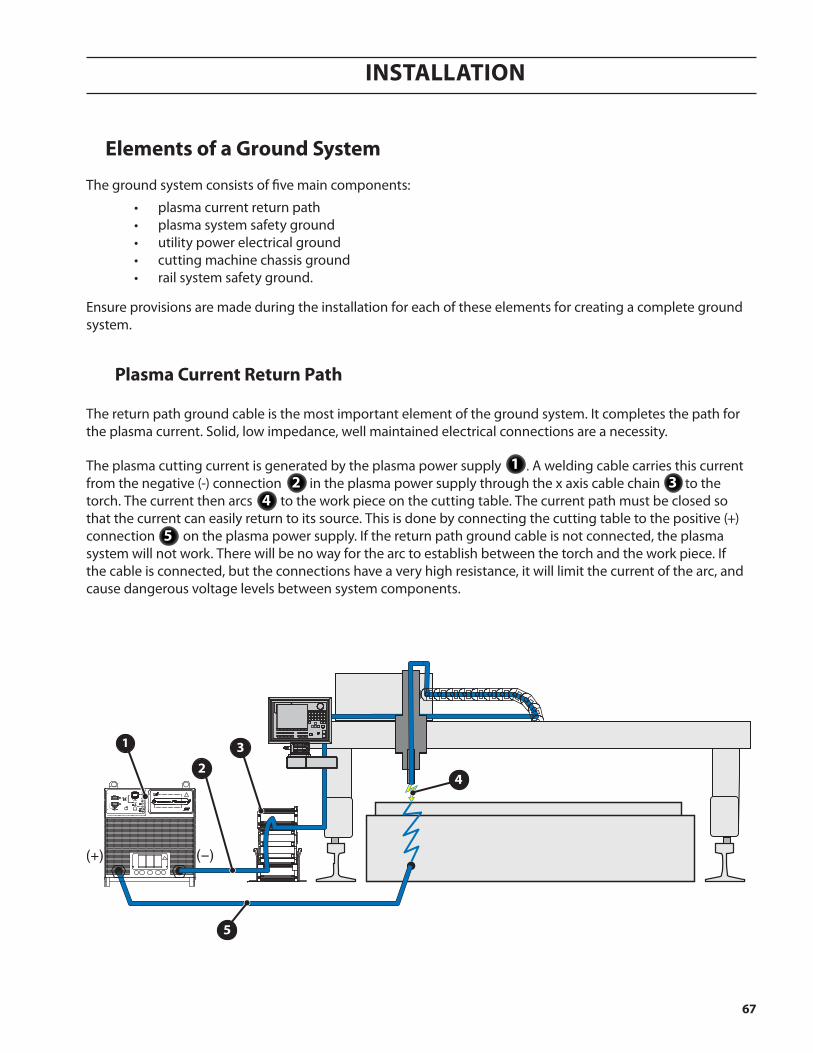
InstallatIon
67
1
23
4
5
The return path ground cable is the most important element of the ground system. It completes the path for the plasma current. Solid, low impedance, well maintained electrical connections are a necessity.
The plasma cutting current is generated by the plasma power supply . A welding cable carries this current from the negative (-) connection in the plasma power supply through the x axis cable chain to the torch. The current then arcs to the work piece on the cutting table. The current path must be closed so that the current can easily return to its source. This is done by connecting the cutting table to the positive (+) connection on the plasma power supply. If the return path ground cable is not connected, the plasma system will not work. There will be no way for the arc to establish between the torch and the work piece. If the cable is connected, but the connections have a very high resistance, it will limit the current of the arc, and cause dangerous voltage levels between system components.
elements of a ground system
The ground system consists of five main components:
• plasma current return path • plasma system safety ground • utility power electrical ground • cutting machine chassis ground • rail system safety ground.
Ensure provisions are made during the installation for each of these elements for creating a complete ground system.
plasma current return path
21
43
5
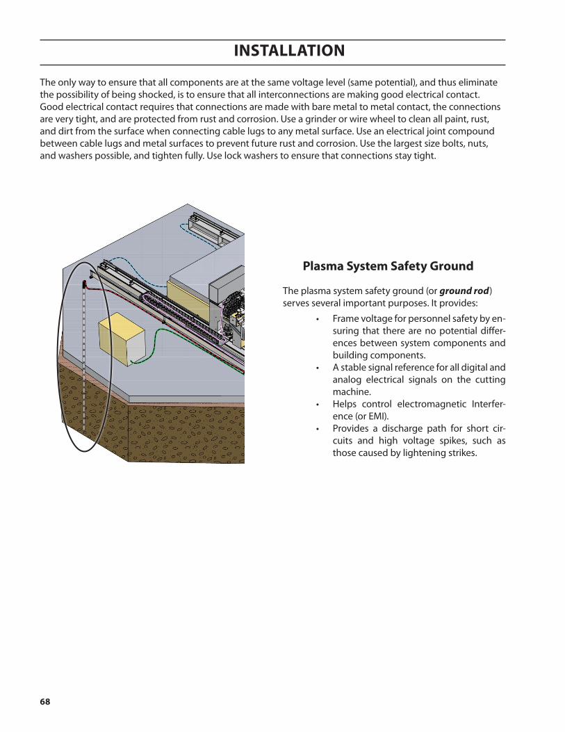
InstallatIon
68
The only way to ensure that all components are at the same voltage level (same potential), and thus eliminate the possibility of being shocked, is to ensure that all interconnections are making good electrical contact. Good electrical contact requires that connections are made with bare metal to metal contact, the connections are very tight, and are protected from rust and corrosion. Use a grinder or wire wheel to clean all paint, rust, and dirt from the surface when connecting cable lugs to any metal surface. Use an electrical joint compound between cable lugs and metal surfaces to prevent future rust and corrosion. Use the largest size bolts, nuts, and washers possible, and tighten fully. Use lock washers to ensure that connections stay tight.
plasma system safety ground
The plasma system safety ground (or ground rod) serves several important purposes. It provides:
• Frame voltage for personnel safety by en-suring that there are no potential differ-ences between system components and building components.
• A stable signal reference for all digital and analog electrical signals on the cutting machine.
• Helps control electromagnetic Interfer-ence (or EMI).
• Provides a discharge path for short cir-cuits and high voltage spikes, such as those caused by lightening strikes.

InstallatIon
69
Misconception about Earth ground rods.
There are many misconceptions about the ground rod, and the role it plays in reducing electromagnetic interference. In theory, the ground rod is present to eliminate possible potential differences between equipment and building structures. However many people believe that the ground rod allows all radio frequency noise to be absorbed and disappear into the Earth. Experience has shown that a good ground rod will eliminate radio frequency noise problems.
1
1
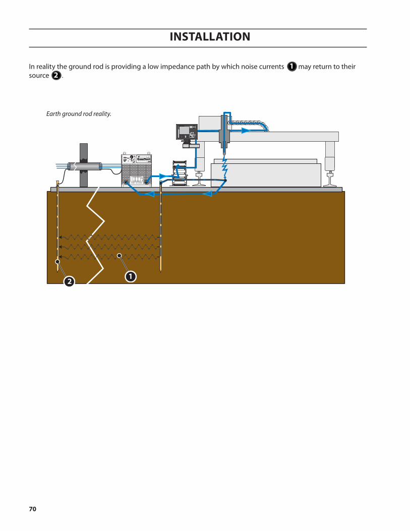
InstallatIon
70
In reality the ground rod is providing a low impedance path by which noise currents may return to their source .
Earth ground rod reality.
12
21

InstallatIon
71
rail system safety ground
The rail system safety ground makes sure that the entire rail is at ground potential, eliminating any possible shock hazard, and providing backup for the machine chassis ground in case of a plasma current short circuit. All four corners of the rail system should be connected to the cutting table.

InstallatIon
72
earth ground rod
The best way to make sure that your Earth ground connection is optimized is to enlist the services of a professional. There are a number of engineering firms which specializes in designing and installing Earth grounding systems. However, if this option cannot be used, then there are several things which can be done to ensure that your Earth ground connection is good:
ground rod
The ground rod itself can be optimized in two ways: length and diameter. The longer the grounding rod, the better the connection. The same is true for diameter: the larger the diameter, the better the connection. However, if the soil resistance is very low, then a ground rod longer than 3m [10 feet] does not make a significant difference. Since soil resistivity is rarely as good as it could be, a standard grounding rod should be 25mm [1 inch] in diameter and 6m [20 feet] long.
soil resistivity
Soil resistivity can be changed in two ways: by altering the mineral content, the moisture content, or both. The ideal solution to poor soil resistivity is to excavate the immediate area and backfill with conditioned soil additives. In extremely dry areas, the moisture content can be improved by installing a drip system which continually moisturizes the soil surrounding the ground rod. A crude way of affecting soil moisture and content is to use salt water, or rock salt to condition the surrounding soil.
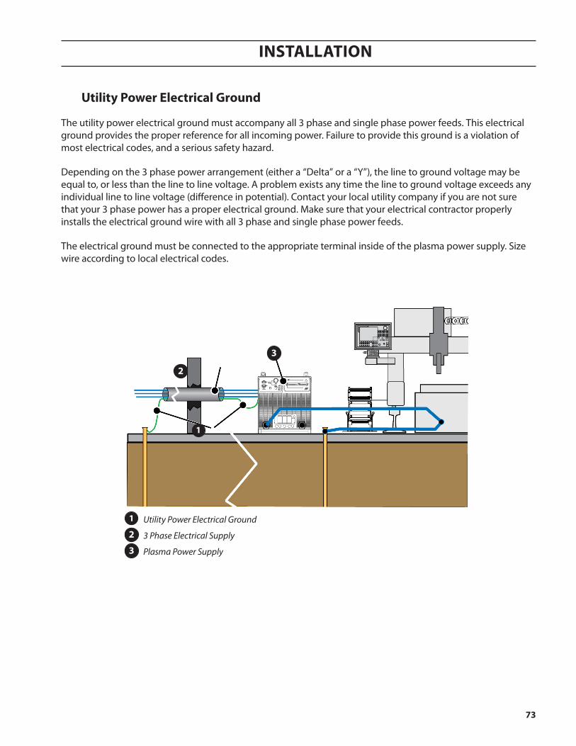
InstallatIon
73
1
2
3
utility power electrical ground
The utility power electrical ground must accompany all 3 phase and single phase power feeds. This electrical ground provides the proper reference for all incoming power. Failure to provide this ground is a violation of most electrical codes, and a serious safety hazard.
Depending on the 3 phase power arrangement (either a “Delta” or a “Y”), the line to ground voltage may be equal to, or less than the line to line voltage. A problem exists any time the line to ground voltage exceeds any individual line to line voltage (difference in potential). Contact your local utility company if you are not sure that your 3 phase power has a proper electrical ground. Make sure that your electrical contractor properly installs the electrical ground wire with all 3 phase and single phase power feeds.
The electrical ground must be connected to the appropriate terminal inside of the plasma power supply. Size wire according to local electrical codes.
Utility Power Electrical Ground
3 Phase Electrical Supply
Plasma Power Supply
1
2
3
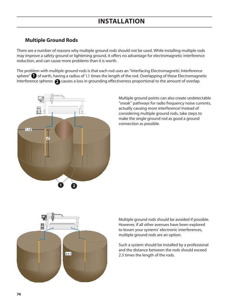
InstallatIon
74
multiple ground rods
There are a number of reasons why multiple ground rods should not be used. While installing multiple rods may improve a safety ground or lightening ground, it offers no advantage for electromagnetic interference reduction, and can cause more problems than it is worth.
The problem with multiple ground rods is that each rod uses an “interfacing Electromagnetic Interference sphere” of earth, having a radius of 1.1 times the length of the rod. Overlapping of these Electromagnetic Interference spheres causes a loss in grounding effectiveness proportional to the amount of overlap.
Multiple ground points can also create undetectable “sneak” pathways for radio frequency noise currents, actually causing more interference! Instead of considering multiple ground rods, take steps to make the single ground rod as good a ground connection as possible.
2.5 l
1.1l
l
1 2
Multiple ground rods should be avoided if possible. However, if all other avenues have been explored to lessen your systems’ electronic interferences, multiple ground rods are an option.
Such a system should be installed by a professional and the distance between the rods should exceed 2.5 times the length of the rods.
21
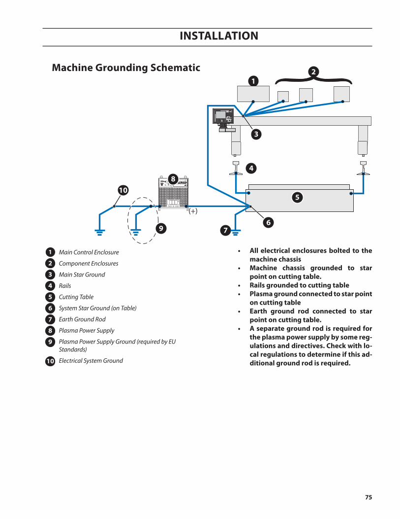
InstallatIon
75
1
7
2
(+)
3
4
5
6
8
9
10
machine grounding schematic
Main Control Enclosure
Component Enclosures
Main Star Ground
Rails
Cutting Table
System Star Ground (on Table)
Earth Ground Rod
Plasma Power Supply
Plasma Power Supply Ground (required by EU Standards)
Electrical System Ground
1
2
3
4
5
6
7
8
9
10
• all electrical enclosures bolted to the machine chassis
• machine chassis grounded to star point on cutting table.
• rails grounded to cutting table• plasma ground connected to star point
on cutting table• earth ground rod connected to star
point on cutting table.• a separate ground rod is required for
the plasma power supply by some reg-ulations and directives. check with lo-cal regulations to determine if this ad-ditional ground rod is required.
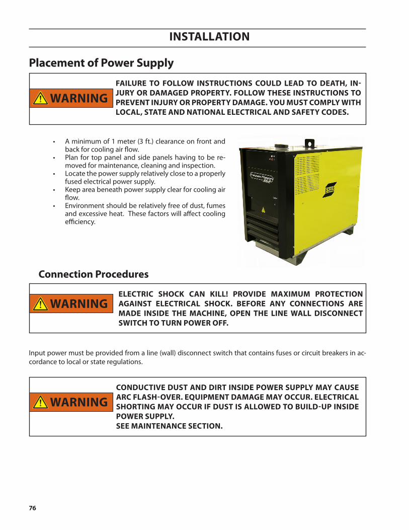
InstallatIon
76
placement of power supply
Warningfailure to folloW instructions coulD leaD to Death, in-JurY or DamageD propertY. folloW these instructions to preVent inJurY or propertY Damage. You must complY With local, state anD national electrical anD safetY coDes.
Warning
Input power must be provided from a line (wall) disconnect switch that contains fuses or circuit breakers in ac-cordance to local or state regulations.
electric shocK can Kill! proViDe maximum protection against electrical shocK. Before anY connections are maDe insiDe the machine, open the line Wall Disconnect sWitch to turn poWer off.
connection procedures
conDuctiVe Dust anD Dirt insiDe poWer supplY maY cause arc flash-oVer. eQuipment Damage maY occur. electrical shorting maY occur if Dust is alloWeD to BuilD-up insiDe poWer supplY. see maintenance section.
Warning
• A minimum of 1 meter (3 ft.) clearance on front and back for cooling air flow.
• Plan for top panel and side panels having to be re-moved for maintenance, cleaning and inspection.
• Locate the power supply relatively close to a properly fused electrical power supply.
• Keep area beneath power supply clear for cooling air flow.
• Environment should be relatively free of dust, fumes and excessive heat. These factors will affect cooling efficiency.
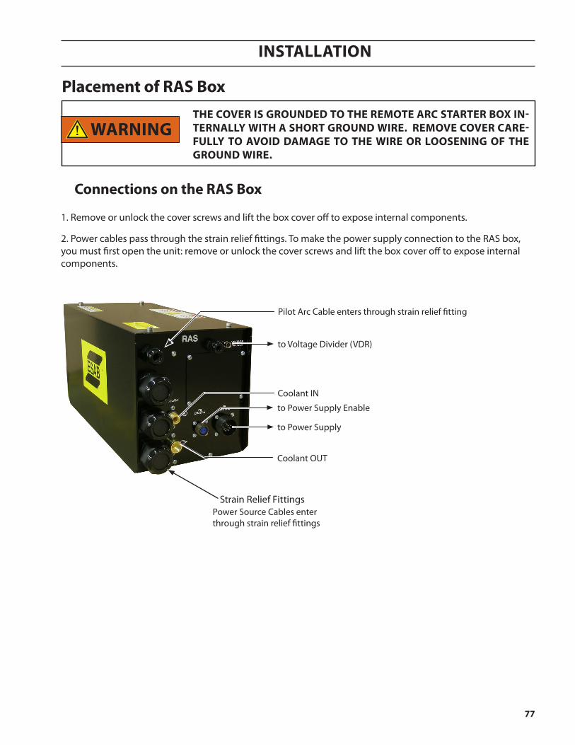
InstallatIon
77
placement of ras Box
connections on the ras Box
1. Remove or unlock the cover screws and lift the box cover off to expose internal components.
the coVer is grounDeD to the remote arc starter Box in-ternallY With a short grounD Wire. remoVe coVer care-fullY to aVoiD Damage to the Wire or loosening of the grounD Wire.
Warning
2. Power cables pass through the strain relief fittings. To make the power supply connection to the RAS box, you must first open the unit: remove or unlock the cover screws and lift the box cover off to expose internal components.
Strain Relief Fittings
Pilot Arc Cable enters through strain relief fitting
Power Source Cables enter through strain relief fittings
to Voltage Divider (VDR)
to Power Supply
to Power Supply Enable
Coolant IN
Coolant OUT
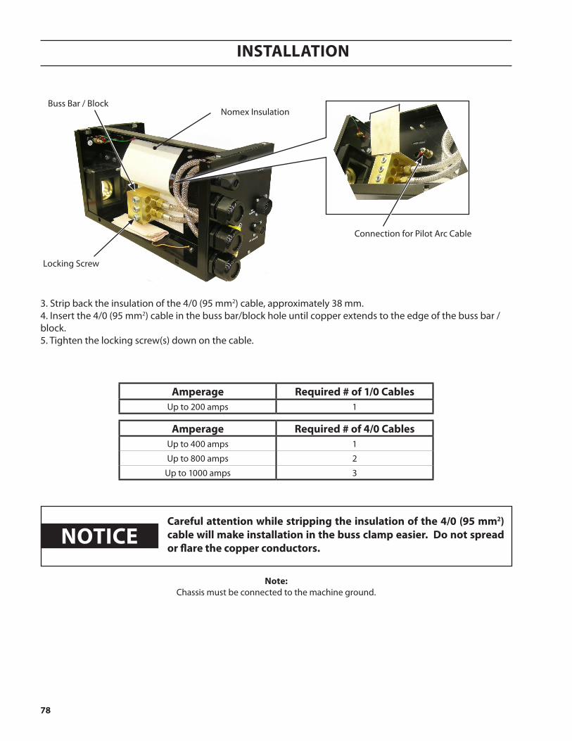
InstallatIon
78
Buss Bar / Block
Locking Screw
Nomex Insulation
Connection for Pilot Arc Cable
careful attention while stripping the insulation of the 4/0 (95 mm2) cable will make installation in the buss clamp easier. Do not spread or flare the copper conductors.
notice
note:Chassis must be connected to the machine ground.
amperage required # of 4/0 cablesUp to 400 amps 1
Up to 800 amps 2
Up to 1000 amps 3
amperage required # of 1/0 cablesUp to 200 amps 1
3. Strip back the insulation of the 4/0 (95 mm2) cable, approximately 38 mm.4. Insert the 4/0 (95 mm2) cable in the buss bar/block hole until copper extends to the edge of the buss bar /block.5. Tighten the locking screw(s) down on the cable.
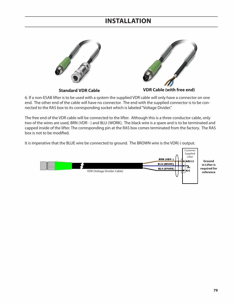
InstallatIon
79
standard VDr cable VDr cable (with free end)
ground in lifter is
required for referenceVDR (Voltage Divider Cable)
Customer Supplied
Lifter
6. If a non-ESAB lifter is to be used with a system the supplied VDR cable will only have a connector on one end. The other end of the cable will have no connector. The end with the supplied connector is to be con-nected to the RAS box to its corresponding socket which is labeled “Voltage Divider.” The free end of the VDR cable will be connected to the lifter. Although this is a three conductor cable, only two of the wires are used, BRN (VDR - ) and BLU (WORK). The black wire is a spare and is to be terminated and capped inside of the lifter. The corresponding pin at the RAS box comes terminated from the factory. The RAS box is not to be modified. It is imperative that the BLUE wire be connected to ground. The BROWN wire is the VDR(-) output.

InstallatIon
80
torch connections
Torch hook-up requires the connection of power cables / coolant hoses, pilot arc cable and chassis ground. On the PT-36 torch, the coolant hoses from the RAS box to the torch also carry electrode power.
ChassisGround
Wire
PilotArc Cable
Power Cable /Coolant
GroundStud
Pilot Arc Connection
Power Cable /Coolant Connections
The pilot arc cable is connected inside the arc starter box. The pilot arc cable also has a green/yellow wire that is connected to a grounding stud.
PG Hose
SG Hose

InstallatIon
81
The PT-36 has two water cooled power cables which must be connected to the negative output from the power supply. The right handed 7/16-20 fitting is on the cable supplying coolant to the torch. The left handed 7/16-20 fitting is on the cable returning coolant from the torch. Both of these cables have a green/yellow wire to be con-nected to the ground stud shown above.
The pilot arc cable is connected to the arc starter box (see Installation section). The pilot arc cable also has a green/yellow wire that is connected to a grounding stud.
electric shock can Kill! • Disconnectprimarypowersourcebeforemakinganyadjust-
ments. • Disconnectprimarysourcebeforedoingmaintenanceonsystem
components. • Donottouchfront-endtorchparts(nozzle,retainingcup,etc.)
without turning primary power off.
Power cables
Ground cable
Pilot Arc cable
Danger
connection of torch to plasma system
connection to the remote arc starter Box
Ground Stud
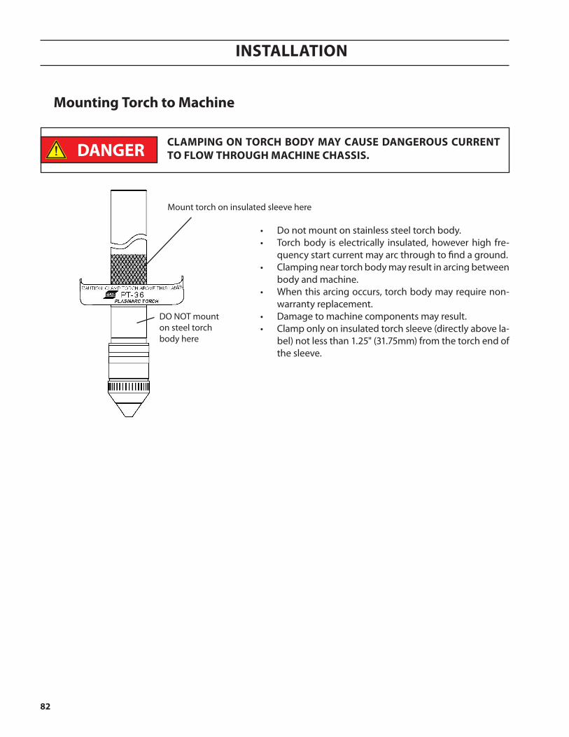
InstallatIon
82
mounting torch to machine
Mount torch on insulated sleeve here
DO NOT mount on steel torch body here
• Do not mount on stainless steel torch body.• Torch body is electrically insulated, however high fre-
quency start current may arc through to find a ground. • Clamping near torch body may result in arcing between
body and machine. • When this arcing occurs, torch body may require non-
warranty replacement. • Damage to machine components may result. • Clamp only on insulated torch sleeve (directly above la-
bel) not less than 1.25" (31.75mm) from the torch end of the sleeve.
clamping on torch BoDY maY cause Dangerous current to floW through machine chassis.
Danger

InstallatIon
83
The CGC regulates the plasma gas and shield gas. For optimum performance, it should always be placed close to torch. Accord-ing to the material being cut, the customer needs to select and connect the correct inlet gases. Inline filters are embedded into the inlet fittings. Please make sure all inlet gases meet the pres-sure and flow requirements.
Connect 24V AC/DC power from PDB, then connect CAN cable to ICH.
placement of cgc
gas pressure
plasma
Argon 125 psi (8.6 bar), 200 SCFH (5.7 SCMH)O2/H35/F5 125 psi (8.6 bar) for O2, 75 psi (5.2 bar) for H35/F5, 255 SCFH (7.2 SCMH)
N2/Air 125 psi (8.6 bar), 255 SCFH (7.2 SCMH)shield N2/Air 125 psi (8.6 bar), 353 SCFH (10.0 SCMH)
air curtain Air 80 psi (5.5 bar), 1200 SCFH (34.0 SCMH)
gas &pressure
maximum gas flow rates - cfh (cmh)With pt-36 torch gas purity
Air (85psi / 5.9bar)Process
269(7.6)
Clean, Dry, Oil FreeFiltered to 25 microns
Nitrogen(125psi / 8.6bar)
385(10.9) 99.99%, Filtered to 25 microns
Oxygen(125psi / 8.6bar)
66(1.9) 99.5%, Filtered to 25 microns

InstallatIon
84
PDB back
CGC front
component connectionsPart numbers and lengths for the cables shown below are provided on the following page.
C
A
B
Compressed Air
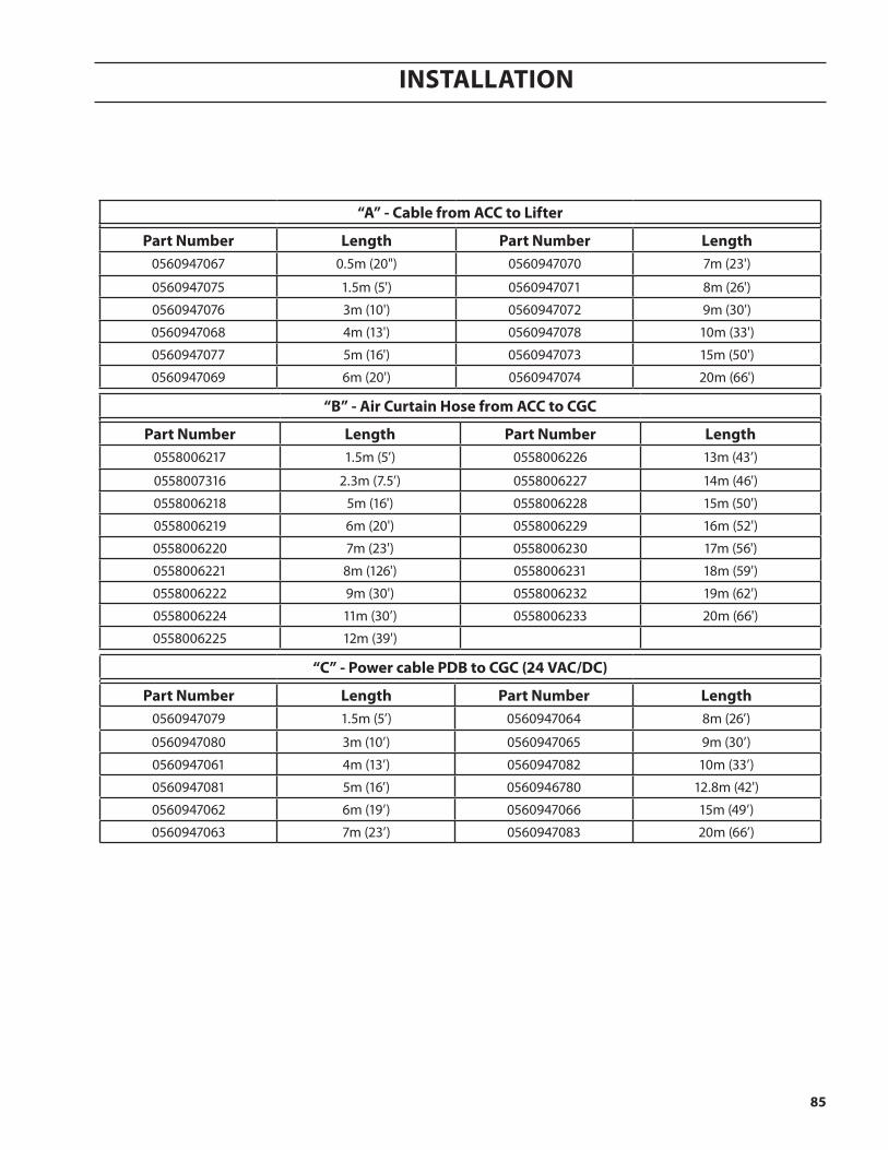
InstallatIon
85
“a” - cable from acc to lifter
part number length part number length0560947067 0.5m (20") 0560947070 7m (23')
0560947075 1.5m (5') 0560947071 8m (26')
0560947076 3m (10') 0560947072 9m (30')
0560947068 4m (13') 0560947078 10m (33')
0560947077 5m (16') 0560947073 15m (50')
0560947069 6m (20') 0560947074 20m (66')
“B” - air curtain hose from acc to cgc
part number length part number length0558006217 1.5m (5’) 0558006226 13m (43’)
0558007316 2.3m (7.5’) 0558006227 14m (46')
0558006218 5m (16') 0558006228 15m (50')
0558006219 6m (20') 0558006229 16m (52')
0558006220 7m (23') 0558006230 17m (56')
0558006221 8m (126') 0558006231 18m (59')
0558006222 9m (30') 0558006232 19m (62')
0558006224 11m (30’) 0558006233 20m (66')
0558006225 12m (39')
“c” - power cable pDB to cgc (24 Vac/Dc)
part number length part number length0560947079 1.5m (5’) 0560947064 8m (26’)
0560947080 3m (10’) 0560947065 9m (30’)
0560947061 4m (13’) 0560947082 10m (33’)
0560947081 5m (16’) 0560946780 12.8m (42')
0560947062 6m (19’) 0560947066 15m (49’)
0560947063 7m (23’) 0560947083 20m (66’)
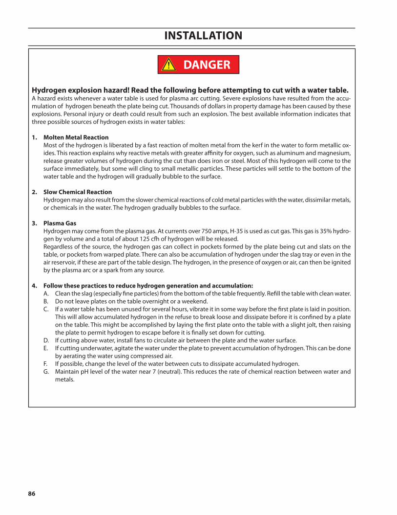
InstallatIon
86
hydrogen explosion hazard! read the following before attempting to cut with a water table.A hazard exists whenever a water table is used for plasma arc cutting. Severe explosions have resulted from the accu-mulation of hydrogen beneath the plate being cut. Thousands of dollars in property damage has been caused by these explosions. Personal injury or death could result from such an explosion. The best available information indicates that three possible sources of hydrogen exists in water tables:
1. molten metal reaction Most of the hydrogen is liberated by a fast reaction of molten metal from the kerf in the water to form metallic ox-
ides. This reaction explains why reactive metals with greater affinity for oxygen, such as aluminum and magnesium, release greater volumes of hydrogen during the cut than does iron or steel. Most of this hydrogen will come to the surface immediately, but some will cling to small metallic particles. These particles will settle to the bottom of the water table and the hydrogen will gradually bubble to the surface.
2. slow chemical reaction Hydrogen may also result from the slower chemical reactions of cold metal particles with the water, dissimilar metals,
or chemicals in the water. The hydrogen gradually bubbles to the surface.
3. plasma gas Hydrogen may come from the plasma gas. At currents over 750 amps, H-35 is used as cut gas. This gas is 35% hydro-
gen by volume and a total of about 125 cfh of hydrogen will be released. Regardless of the source, the hydrogen gas can collect in pockets formed by the plate being cut and slats on the
table, or pockets from warped plate. There can also be accumulation of hydrogen under the slag tray or even in the air reservoir, if these are part of the table design. The hydrogen, in the presence of oxygen or air, can then be ignited by the plasma arc or a spark from any source.
4. follow these practices to reduce hydrogen generation and accumulation: A. Clean the slag (especially fine particles) from the bottom of the table frequently. Refill the table with clean water. B. Do not leave plates on the table overnight or a weekend. C. If a water table has been unused for several hours, vibrate it in some way before the first plate is laid in position.
This will allow accumulated hydrogen in the refuse to break loose and dissipate before it is confined by a plate on the table. This might be accomplished by laying the first plate onto the table with a slight jolt, then raising the plate to permit hydrogen to escape before it is finally set down for cutting.
D. If cutting above water, install fans to circulate air between the plate and the water surface. E. If cutting underwater, agitate the water under the plate to prevent accumulation of hydrogen. This can be done
by aerating the water using compressed air. F. If possible, change the level of the water between cuts to dissipate accumulated hydrogen. G. Maintain pH level of the water near 7 (neutral). This reduces the rate of chemical reaction between water and
metals.
Danger
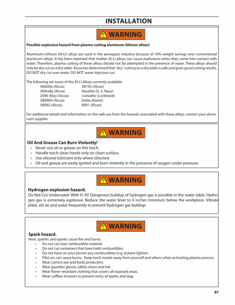
InstallatIon
87
spark hazard.Heat, spatter, and sparks cause fire and burns.
• Donotcutnearcombustiblematerial.• Donotcutcontainersthathaveheldcombustibles.• Donothaveonyourpersonanycombustibles(e.g.butanelighter).• Pilotarccancauseburns.Keeptorchnozzleawayfromyourselfandotherswhenactivatingplasmaprocess.• Wearcorrecteyeandbodyprotection.• Weargauntletgloves,safetyshoesandhat.• Wearflame-retardantclothingthatcoversallexposedareas.• Wearcufflesstrouserstoprevententryofsparksandslag.
possible explosion hazard from plasma cutting aluminum-lithium alloys!
Aluminum-Lithium (Al-Li) alloys are used in the aerospace industry because of 10% weight savings over conventional aluminum alloys. It has been reported that molten Al-Li alloys can cause explosions when they come into contact with water. Therefore, plasma cutting of these alloys should not be attempted in the presence of water. These alloys should only be dry cut on a dry table. Alcoa has determined that "dry" cutting on a dry table is safe and gives good cutting results. DO NOT dry cut over water. DO NOT water injection cut.
The following are some of the Al-Li alloys currently available: Alithlite (Alcoa) X8192 (Alcoa) Alithally (Alcoa) Navalite (U. S. Navy) 2090 Alloy (Alcoa) Lockalite (Lockheed) X8090A (Alcoa) Kalite (Kaiser) X8092 (Alcoa) 8091 (Alcan)
For additional details and information on the safe use from the hazards associated with these alloys, contact your alumi-num supplier.
oil and grease can Burn Violently! • Neveruseoilorgreaseonthistorch.• Handletorchcleanhandsonlyoncleansurface.• Usesiliconelubricantonlywheredirected.• Oilandgreaseareeasilyignitedandburnviolentlyinthepresenceofoxygenunderpressure.
hydrogen explosion hazard.Do Not Cut Underwater With H-35! Dangerous buildup of hydrogen gas is possible in the water table. Hydro-gen gas is extremely explosive. Reduce the water level to 4 inches minimum below the workpiece. Vibrate plate, stir air and water frequently to prevent hydrogen gas buildup.
Warning
Warning
Warning
Warning
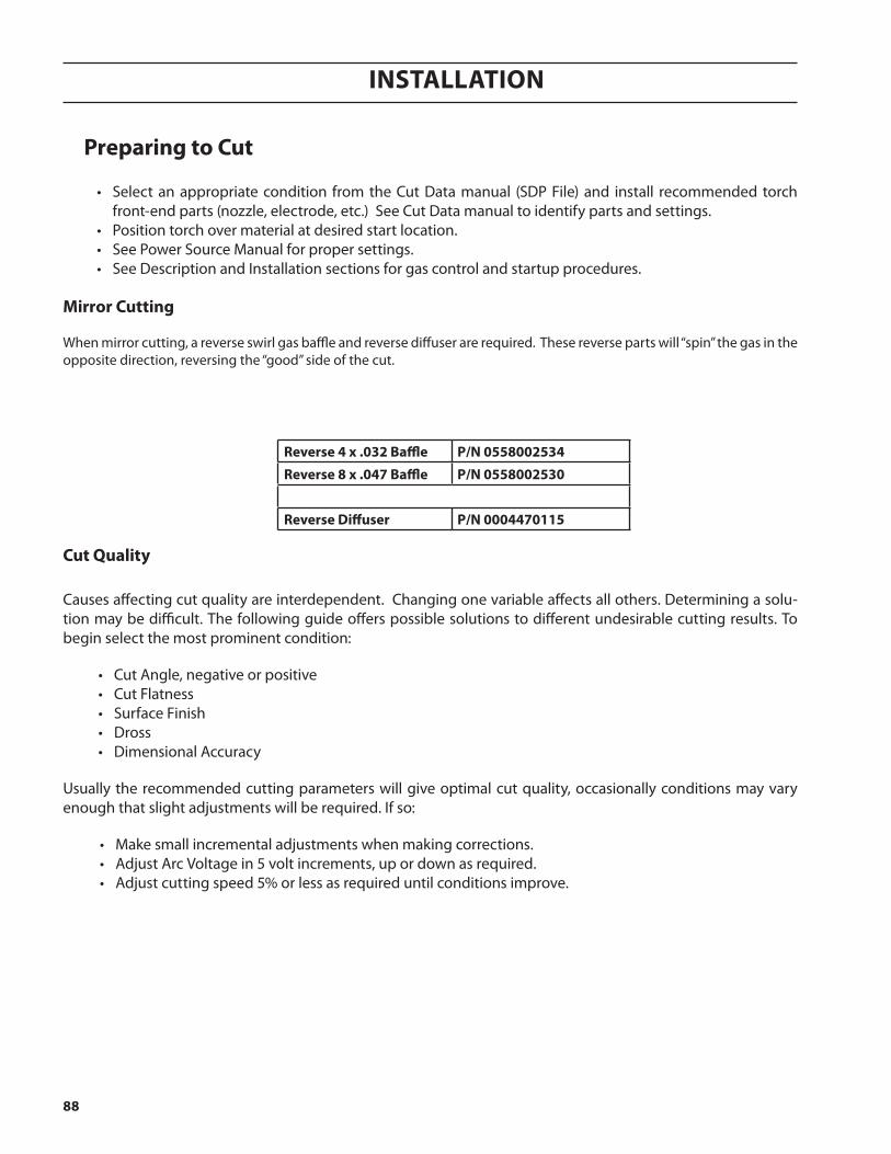
InstallatIon
88
preparing to cut
• Select an appropriate condition from the Cut Data manual (SDP File) and install recommended torch front-end parts (nozzle, electrode, etc.) See Cut Data manual to identify parts and settings.
• Position torch over material at desired start location. • See Power Source Manual for proper settings. • See Description and Installation sections for gas control and startup procedures.
mirror cutting When mirror cutting, a reverse swirl gas baffle and reverse diffuser are required. These reverse parts will “spin” the gas in the opposite direction, reversing the “good” side of the cut.
cut Quality
Causes affecting cut quality are interdependent. Changing one variable affects all others. Determining a solu-tion may be difficult. The following guide offers possible solutions to different undesirable cutting results. To begin select the most prominent condition:
• Cut Angle, negative or positive• Cut Flatness• Surface Finish• Dross• Dimensional Accuracy
Usually the recommended cutting parameters will give optimal cut quality, occasionally conditions may vary enough that slight adjustments will be required. If so:
• Make small incremental adjustments when making corrections.• Adjust Arc Voltage in 5 volt increments, up or down as required.• Adjust cutting speed 5% or less as required until conditions improve.
reverse 4 x .032 Baffle p/n 0558002534
reverse 8 x .047 Baffle p/n 0558002530
reverse Diffuser p/n 0004470115
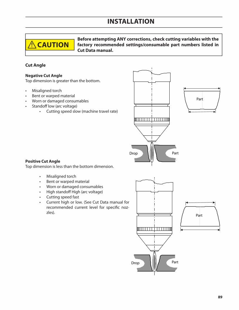
InstallatIon
89
positive cut angleTop dimension is less than the bottom dimension.
• Misaligned torch• Bent or warped material• Worn or damaged consumables• High standoff High (arc voltage)• Cutting speed fast• Current high or low. (See Cut Data manual for
recommended current level for specific noz-zles).
Part
Drop Part
Before attempting anY corrections, check cutting variables with the factory recommended settings/consumable part numbers listed in cut Data manual.
cut angle negative cut angleTop dimension is greater than the bottom.
• Misaligned torch• Bent or warped material• Worn or damaged consumables• Standoff low (arc voltage)
• Cutting speed slow (machine travel rate)
Part
Part
Drop
caution
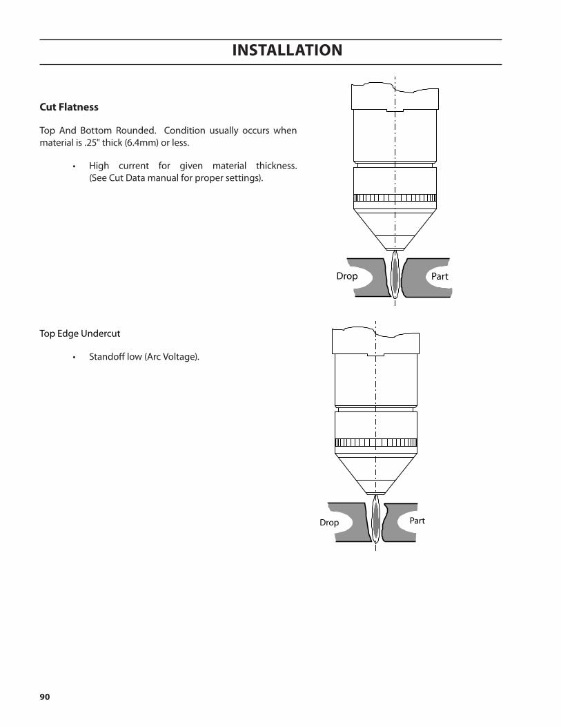
InstallatIon
90
cut flatness
Top And Bottom Rounded. Condition usually occurs when material is .25" thick (6.4mm) or less.
• High current for given material thickness. (See Cut Data manual for proper settings).
Drop Part
Top Edge Undercut
• Standoff low (Arc Voltage).
Part Drop
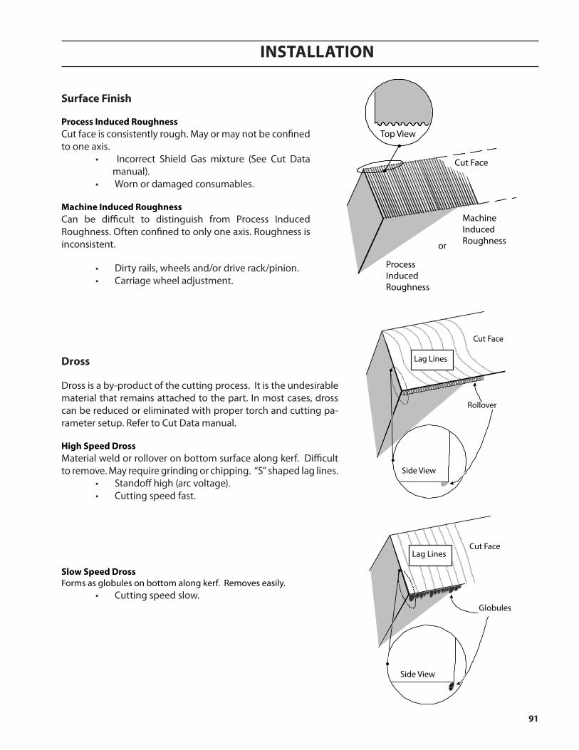
InstallatIon
91
surface finish
process induced roughnessCut face is consistently rough. May or may not be confined to one axis.
• Incorrect Shield Gas mixture (See Cut Data manual).
• Worn or damaged consumables. machine induced roughnessCan be difficult to distinguish from Process Induced Roughness. Often confined to only one axis. Roughness is inconsistent.
• Dirty rails, wheels and/or drive rack/pinion.• Carriage wheel adjustment.
or
MachineInducedRoughness
ProcessInducedRoughness
Cut Face
Top View
Dross
Dross is a by-product of the cutting process. It is the undesirable material that remains attached to the part. In most cases, dross can be reduced or eliminated with proper torch and cutting pa-rameter setup. Refer to Cut Data manual.
high speed DrossMaterial weld or rollover on bottom surface along kerf. Difficult to remove. May require grinding or chipping. “S” shaped lag lines.
• Standoff high (arc voltage).• Cutting speed fast.
slow speed DrossForms as globules on bottom along kerf. Removes easily.
• Cutting speed slow.
Side View
Cut Face
Rollover
Lag Lines
Side View
Globules
Cut FaceLag Lines

InstallatIon
92
top DrossAppears as splatter on top of material. Usually removes easily.
• Cutting speed fast• Standoff high (arc voltage)
intermittent DrossAppears on top or bottom along kerf. Non-continuous. Can appear as any kind of dross.
• Possible worn consumables
other factors affecting Dross;• Material temperature• Heavy mill scale or rust• High carbon alloys
Dimensional accuracy
Generally using the slowest possible speed (within approved levels) will optimize part accuracy. Select consumables to allow a lower arc voltage and slower cutting speed.
Side View
Cut Face
Splatter
recommended cutting speed and arc voltage will give optimal cut-ting performance in most cases. small incremental adjustments may be needed due to material quality, material temperature and specific alloy. the operator should remember that all cutting variables are in-terdependent. changing one setting affects all others and cut quality could deteriorate. always start at the recommended settings.
Before attempting anY corrections, check cutting variables with the factory recommended settings/consumable part numbers listed in the cut Data manual.
Small incremental adjustments may be needed due to material quality, material temperature and specific alloy. The operator should remember that all cutting variables are interdependent. Changing one setting affects all others and cut quality could deteriorate. Always start at the recommended settings. Before attempting ANY corrections, check cutting variables with the factory recommended settings/consumable part numbers listed in the Cut Data manual.
Recommended cutting speed and arc voltage will give optimal cutting performance.
notice
caution
caution
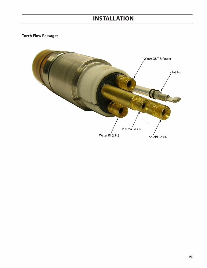
InstallatIon
93
torch flow passages
Shield Gas INWater IN (L.H.)
Water OUT & Power
Plasma Gas IN
Pilot Arc

InstallatIon
94

maintenance/troubleshooting

Maintenance/troubleshooting
96
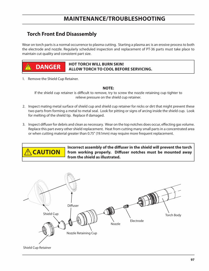
Maintenance/troubleshooting
97
Wear on torch parts is a normal occurrence to plasma cutting. Starting a plasma arc is an erosive process to both the electrode and nozzle. Regularly scheduled inspection and replacement of PT-36 parts must take place to maintain cut quality and consistent part size.
1. Remove the Shield Cup Retainer.
note: If the shield cup retainer is difficult to remove, try to screw the nozzle retaining cup tighter to
relieve pressure on the shield cup retainer.
2. Inspect mating metal surface of shield cup and shield cup retainer for nicks or dirt that might prevent these two parts from forming a metal to metal seal. Look for pitting or signs of arcing inside the shield cup. Look for melting of the shield tip. Replace if damaged.
3. Inspect diffuser for debris and clean as necessary. Wear on the top notches does occur, effecting gas volume. Replace this part every other shield replacement. Heat from cutting many small parts in a concentrated area or when cutting material greater than 0.75" (19.1mm) may require more frequent replacement.
Shield Cup Retainer
Nozzle Retaining Cup
NozzleElectrode
Torch Body
hot torch Will Burn sKin! alloW torch to cool Before serVicing.
Shield Cup
Diffuser
incorrect assembly of the diffuser in the shield will prevent the torch from working properly. Diffuser notches must be mounted away from the shield as illustrated.
caution
Danger
torch front end Disassembly
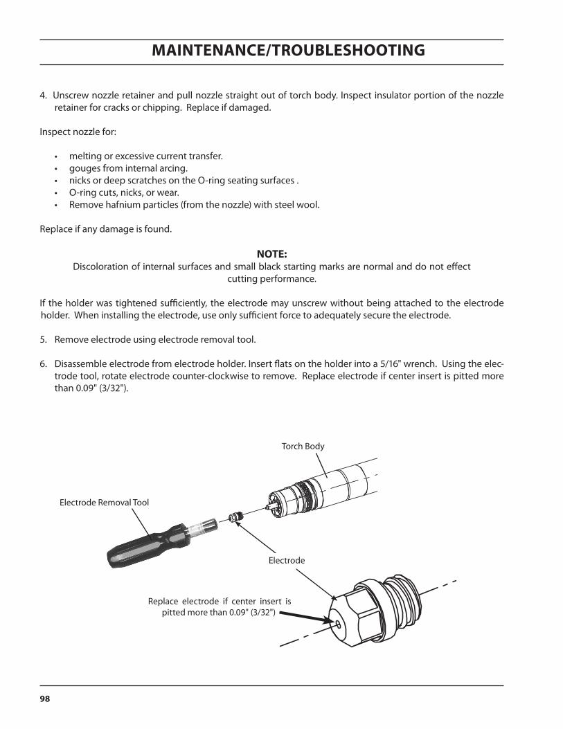
Maintenance/troubleshooting
98
4. Unscrew nozzle retainer and pull nozzle straight out of torch body. Inspect insulator portion of the nozzle retainer for cracks or chipping. Replace if damaged.
Inspect nozzle for:
• melting or excessive current transfer. • gouges from internal arcing. • nicks or deep scratches on the O-ring seating surfaces .• O-ring cuts, nicks, or wear. • Remove hafnium particles (from the nozzle) with steel wool.
Replace if any damage is found.
note: Discoloration of internal surfaces and small black starting marks are normal and do not effect
cutting performance.
If the holder was tightened sufficiently, the electrode may unscrew without being attached to the electrode holder. When installing the electrode, use only sufficient force to adequately secure the electrode.
5. Remove electrode using electrode removal tool.
6. Disassemble electrode from electrode holder. Insert flats on the holder into a 5/16" wrench. Using the elec-trode tool, rotate electrode counter-clockwise to remove. Replace electrode if center insert is pitted more than 0.09" (3/32").
Torch Body
Electrode Removal Tool
Electrode
Replace electrode if center insert is pitted more than 0.09" (3/32")
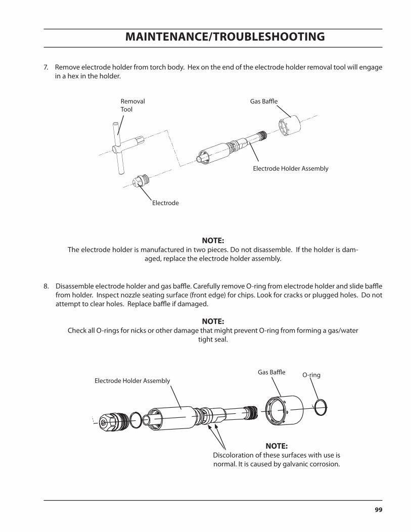
Maintenance/troubleshooting
99
7. Remove electrode holder from torch body. Hex on the end of the electrode holder removal tool will engage in a hex in the holder.
note: The electrode holder is manufactured in two pieces. Do not disassemble. If the holder is dam-
aged, replace the electrode holder assembly.
8. Disassemble electrode holder and gas baffle. Carefully remove O-ring from electrode holder and slide baffle from holder. Inspect nozzle seating surface (front edge) for chips. Look for cracks or plugged holes. Do not attempt to clear holes. Replace baffle if damaged.
note: Check all O-rings for nicks or other damage that might prevent O-ring from forming a gas/water
tight seal.
Electrode Holder AssemblyGas Baffle O-ring
Electrode
Removal Tool
Gas Baffle
Electrode Holder Assembly
note: Discoloration of these surfaces with use is normal. It is caused by galvanic corrosion.
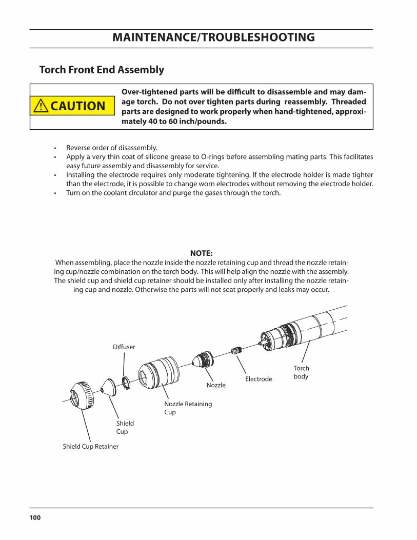
Maintenance/troubleshooting
100
torch front end assembly
• Reverse order of disassembly. • Apply a very thin coat of silicone grease to O-rings before assembling mating parts. This facilitates
easy future assembly and disassembly for service. • Installing the electrode requires only moderate tightening. If the electrode holder is made tighter
than the electrode, it is possible to change worn electrodes without removing the electrode holder. • Turn on the coolant circulator and purge the gases through the torch.
note: When assembling, place the nozzle inside the nozzle retaining cup and thread the nozzle retain-ing cup/nozzle combination on the torch body. This will help align the nozzle with the assembly. The shield cup and shield cup retainer should be installed only after installing the nozzle retain-
ing cup and nozzle. Otherwise the parts will not seat properly and leaks may occur.
Shield Cup Retainer
Diffuser
Shield Cup
Nozzle RetainingCup
NozzleElectrode
Torch body
over-tightened parts will be difficult to disassemble and may dam-age torch. Do not over tighten parts during reassembly. threaded parts are designed to work properly when hand-tightened, approxi-mately 40 to 60 inch/pounds.
caution

Maintenance/troubleshooting
101
Use of a speedloader, p/n 0558006164, will ease assembly of the torch front end parts.
step 1. To use the speedloader, first insert the nozzle into the nozzle retaining cup.
step 2. Screw the speedloader into the nozzle retaining cup to secure the nozzle.
step 3. Secure retaining nut on nozzle with preassembly tool, p/n 0558005917 included with the speedloader.
step 4. Remove the speedloader. It is very important to remove the speedloader to ensure proper seating of the remaining parts.
step 5. Insert the diffuser into the shield cup.
step 6. Insert the nozzle retaining cup assembly into the shield cup retainer.
step 7. Screw shield cup retainer assembly onto nozzle re-taining cup assembly.
torch front end assembly using the speedloader
Nozzle retaining cup assembly
Diffuser
Shield Cup
Nozzle Retaining Cup
Nozzle
Retaining nutp/n 0558005916
Shield cup retainer assembly
Preassembly tool
Shield cup retainer
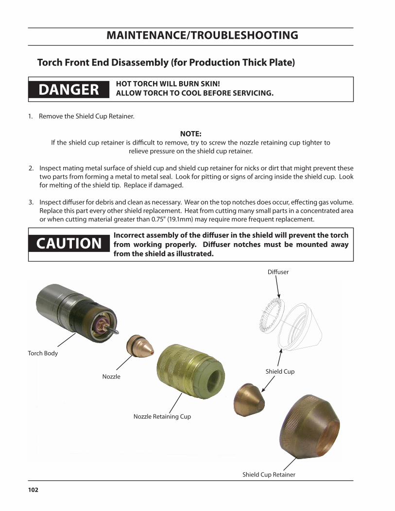
Maintenance/troubleshooting
102
torch front end Disassembly (for production thick plate)
Nozzle
1. Remove the Shield Cup Retainer.
note: If the shield cup retainer is difficult to remove, try to screw the nozzle retaining cup tighter to
relieve pressure on the shield cup retainer.
2. Inspect mating metal surface of shield cup and shield cup retainer for nicks or dirt that might prevent these two parts from forming a metal to metal seal. Look for pitting or signs of arcing inside the shield cup. Look for melting of the shield tip. Replace if damaged.
3. Inspect diffuser for debris and clean as necessary. Wear on the top notches does occur, effecting gas volume. Replace this part every other shield replacement. Heat from cutting many small parts in a concentrated area or when cutting material greater than 0.75" (19.1mm) may require more frequent replacement.
Shield Cup Retainer
Nozzle Retaining Cup
Torch Body
Danger hot torch Will Burn sKin! alloW torch to cool Before serVicing.
Shield Cup
Diffuser
cautionincorrect assembly of the diffuser in the shield will prevent the torch from working properly. Diffuser notches must be mounted away from the shield as illustrated.

Maintenance/troubleshooting
103
4. Unscrew nozzle retainer and pull nozzle straight out of torch body. Inspect insulator portion of the nozzle retainer for cracks or chipping. Replace if damaged.
Inspect nozzle for:
• melting or excessive current trans-fer.
• gouges from internal arcing. • nicks or deep scratches on the O-
ring seating surfaces. • O-ring cuts, nicks, or wear. • Remove tungsten particles (from
the nozzle) with steel wool.
Replace if any damage is found.
note: Discoloration of internal surfaces and small black starting marks are normal and do not effect
cutting performance.
If the holder was tightened sufficiently, the electrode may unscrew without being attached to the electrode holder. When installing the electrode, use only sufficient force to adequately secure the electrode.
5. Remove electrode using electrode removal tool.
6. Disassemble electrode from electrode holder. Insert flats on the holder into a 5/16" wrench. Using the elec-trode tool, rotate electrode counter-clockwise to remove. Replace electrode if center is pitted more than 0.06" (1/16") or if the flat has become irregular in shape or is worn to a larger diameter.
Torch Body
Electrode Removal Tool
Electrode
Electrode, TungstenCollet Body
Collet
Nozzle
Nozzle Retaining Cup
Torch Body
note: The electrode has two usable ends. When one end is worn, flip electrode to
other end for continued use.

Maintenance/troubleshooting
104
7. Remove electrode holder from torch body. Hex on the end of the electrode holder removal tool will engage in a hex in the holder.
8. Disassemble electrode holder and gas baffle. Carefully remove O-ring from electrode holder and slide baffle from holder. Inspect nozzle seating surface (front edge) for chips. Look for cracks or plugged holes. Do not attempt to clear holes. Replace baffle if damaged.
note: Check all O-rings for nicks or other damage that might prevent O-ring from forming a gas/water
tight seal.
Electrode Holder
Gas Baffle
O-ring (located underneath baffle)
Removal Tool
Electrode Holder
Torch Body
Pull Gas Baffle back to remove and access o-ring

Maintenance/troubleshooting
105
torch front end assembly (for production thick plate)
• Reverse order of disassembly. • Apply a very thin coat of silicone grease to O-rings before assembling mating parts. This facilitates
easy future assembly and disassembly for service. • Installing the electrode requires only moderate tightening.
over tightened parts will be difficult to disassemble and may dam-age torch. Do not over tighten parts during reassembly. threaded parts are designed to work properly when hand tightened, approxi-mately 40 to 60 inch/pounds.
1. Replace electrode holder in torch body. Hex on the end of the electrode holder removal tool will engage in a hex in the holder.
2. To replace the electrode, assemble collet, collet body and electrode. Insert electrode assembly into the elec-trode removal tool and ensure electrode makes con-tact with bottom of tool hole (electrode will fall into place).
Electrode, TungstenCollet Body
Collet
Torch Body
caution
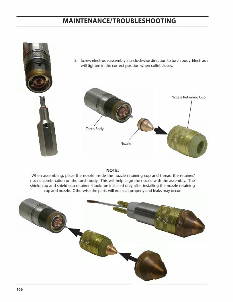
Maintenance/troubleshooting
106
note: When assembling, place the nozzle inside the nozzle retaining cup and thread the retainer/nozzle combination on the torch body. This will help align the nozzle with the assembly. The shield cup and shield cup retainer should be installed only after installing the nozzle retaining
cup and nozzle. Otherwise the parts will not seat properly and leaks may occur.
3. Screw electrode assembly in a clockwise direction to torch body. Electrode will tighten in the correct position when collet closes.
Nozzle
Torch Body
Nozzle Retaining Cup
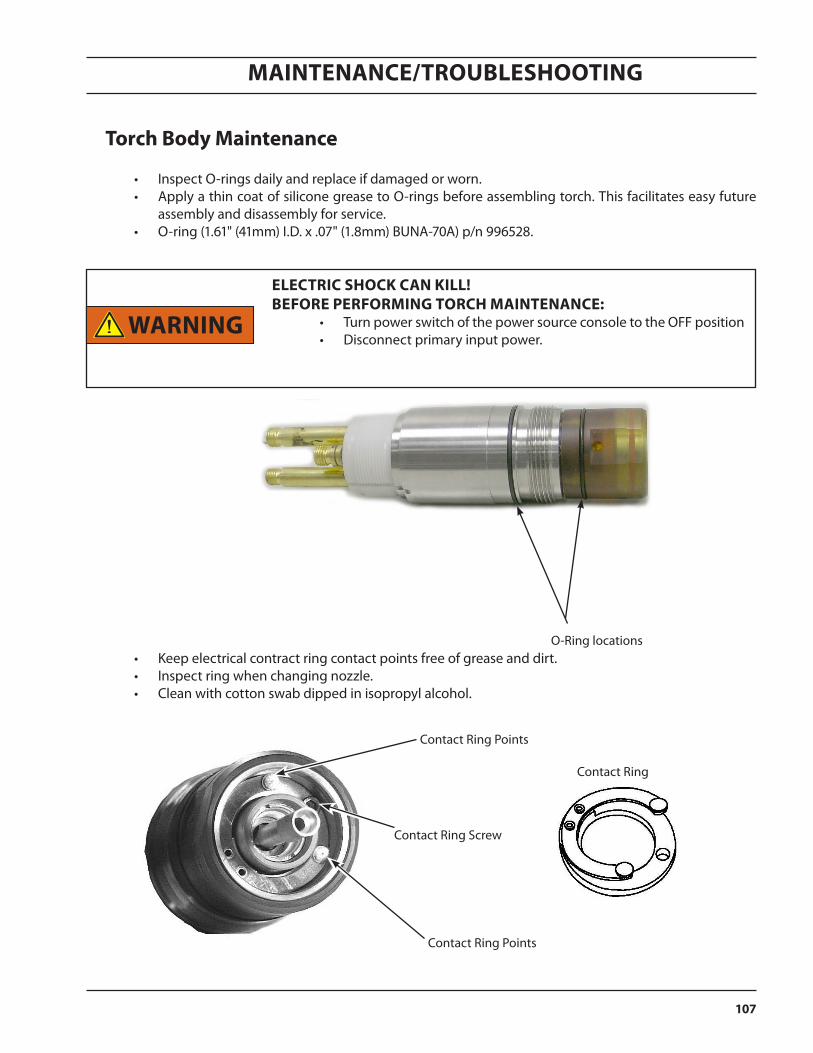
Maintenance/troubleshooting
107
electric shocK can Kill! Before performing torch maintenance:
• Turn power switch of the power source console to the OFF position • Disconnect primary input power.
torch Body maintenance
• Inspect O-rings daily and replace if damaged or worn. • Apply a thin coat of silicone grease to O-rings before assembling torch. This facilitates easy future
assembly and disassembly for service. • O-ring (1.61" (41mm) I.D. x .07" (1.8mm) BUNA-70A) p/n 996528.
O-Ring locations • Keep electrical contract ring contact points free of grease and dirt. • Inspect ring when changing nozzle. • Clean with cotton swab dipped in isopropyl alcohol.
Contact Ring Points
Contact Ring
Contact Ring Points
Contact Ring Screw
Warning
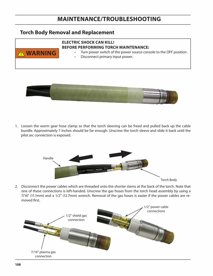
Maintenance/troubleshooting
108
torch Body removal and replacement
electric shocK can Kill! Before performing torch maintenance:
• Turn power switch of the power source console to the OFF position .• Disconnect primary input power.
Torch Body
Handle
1. Loosen the worm gear hose clamp so that the torch sleeving can be freed and pulled back up the cable bundle. Approximately 7 inches should be far enough. Unscrew the torch sleeve and slide it back until the pilot arc connection is exposed.
2. Disconnect the power cables which are threaded onto the shorter stems at the back of the torch. Note that one of these connections is left-handed. Unscrew the gas hoses from the torch head assembly by using a 7/16" (11.1mm) and a 1/2" (12.7mm) wrench. Removal of the gas hoses is easier if the power cables are re-moved first.
7/16" plasma gas connection
1/2" shield gas connection
1/2" power cable connections
Warning
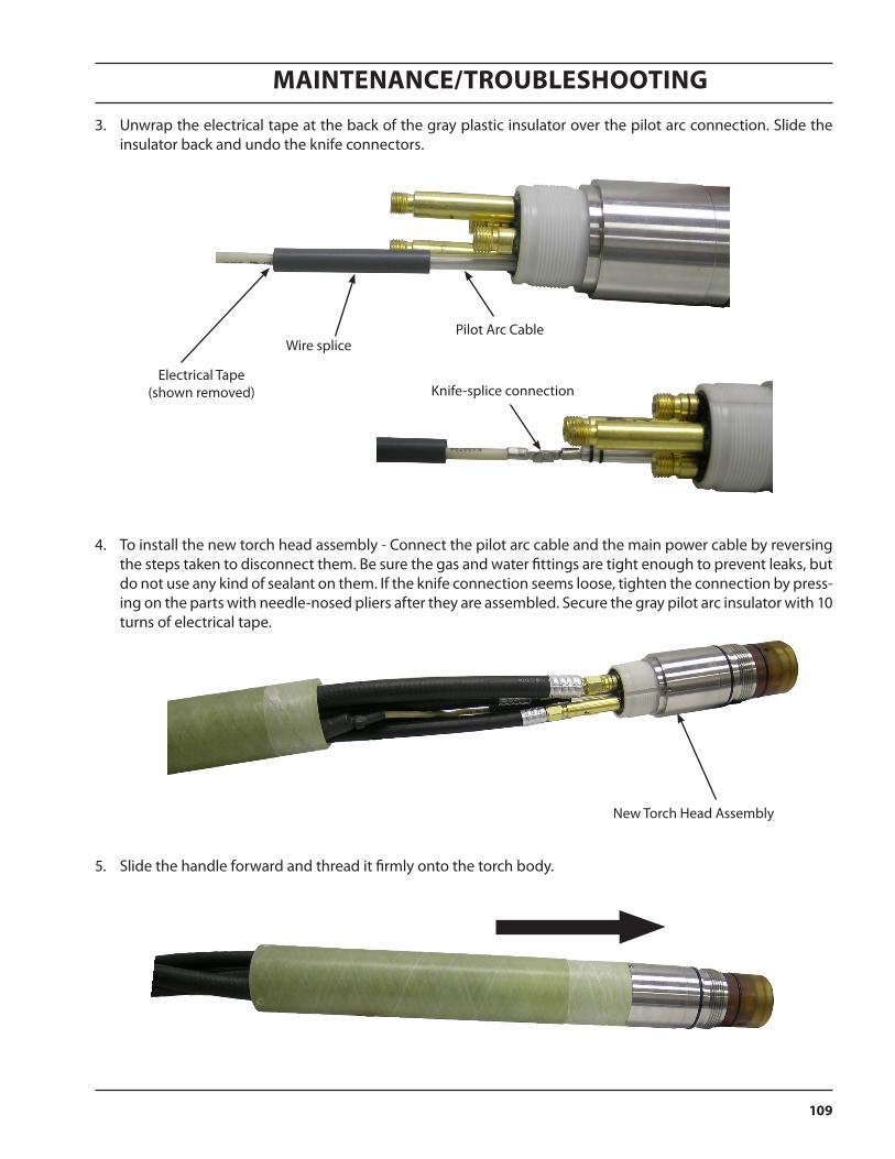
Maintenance/troubleshooting
109
3. Unwrap the electrical tape at the back of the gray plastic insulator over the pilot arc connection. Slide the insulator back and undo the knife connectors.
Electrical Tape(shown removed)
Pilot Arc CableWire splice
Knife-splice connection
5. Slide the handle forward and thread it firmly onto the torch body.
4. To install the new torch head assembly - Connect the pilot arc cable and the main power cable by reversing the steps taken to disconnect them. Be sure the gas and water fittings are tight enough to prevent leaks, but do not use any kind of sealant on them. If the knife connection seems loose, tighten the connection by press-ing on the parts with needle-nosed pliers after they are assembled. Secure the gray pilot arc insulator with 10 turns of electrical tape.
New Torch Head Assembly
Maintenance/troubleshooting
110
reduced consumable life
1. cutting up skeletons
Cutting skeletons (discarded material left after all pieces have been removed from a plate). Their removal from the table can adversely affect electrode life by:
• Causing the torch to run off the work. • Greatly increasing the start frequency. This is mainly a problem for O2 cutting and can be alleviated by
choosing a path with a minimum number of starts. • Increasing likelihood that the plate will spring up against the nozzle causing a double arc. This can be
mitigated by careful operator attention and by increasing standoff and reducing cutting speeds.
If possible, use an OXWELD torch for skeleton cutting or operate the PT-36 at a high standoff. 2. height control problems
• Torch crashing is usually caused by a change in arc voltage when an automatic height control is used. The voltage change is usually the result of plate falling away from the arc. Disabling the height control and extinguishing the arc earlier when finishing the cut on a falling plate can effectively eliminate these problems.
• Torch crashing can also occur at the start if travel delay is excessive. This is more likely to occur with thin material. Reduce delay or disable the height control.
• Torch crashing can also be caused by a faulty height control.
3. piercing standoff too low Increase pierce standoff 4. starting on edges with continuous pilot arc Position torch more carefully or start on adjacent scrap material. 5. Work flipping The nozzle may be damaged if the torch hits a flipped up part.
6. catching on pierce spatter Increase standoff or start with longer lead-in.
7. pierce not complete before starting Increase initial delay time.
8. coolant flow rate low, Correct settings plasma gas flow rate high, current set too high
9. coolant leaks in torch Repair leaks

Maintenance/troubleshooting
111
checking for coolant leaks
Coolant leaks can originate from seals on the electrode, electrode holder, nozzle, and torch body. Leaks could also originate from a crack in the insulating material of the torch or nozzle retaining cup or from a power cable.
To check for leaks from any source remove the shield cup, clean off the torch, purge it, and place it over a clean dry plate. With the gases off, run the water cooler for several minutes and watch for leaks. Turn on the plasma gas and watch for any mist from the nozzle exit. If there isn’t any, turn off the plasma gas, turn on the shield gas, and watch for any mist from the shield gas passages in the nozzle retaining cup.
If a leak appears to be coming from the nozzle orifice, remove and inspect the o-rings on the nozzle, electrode, and electrode holder. Check the sealing surfaces on the electrode holder and stainless steel torch liner.
If you suspect that a leak is coming from the electrode itself, you can install a 100 to 200 amp 2-piece nozzle base without a nozzle tip. After purging, run the water cooler with the gas off and observe the end of the electrode. If water is seen to collect there, make sure it is not running down the side of the electrode from a leak at an o-ring seal.
if it is necessary to supply power to the power source to run the wa-ter cooler, it is possible to have high voltages at the torch with no arc present. never touch the torch with the power source energized.
Warning

Maintenance/troubleshooting
112

replacement parts

114
Replacement paRts
115
Replacement paRts
generalAlways provide the serial number of the unit on which the parts will be used. The serial number is stamped on the unit nameplate.
To ensure proper operation, it is recommended that only genuine ESAB parts and products be used with this equipment. The use of non-ESAB parts may void your warranty.
Replacement parts may be ordered from your ESAB Distributor.
Be sure to indicate any special shipping instructions when ordering replacement parts.
Refer to the Communications Guide located on the back page of this manual for a list of customer service phone numbers.
ordering
Items listed in the assembly drawing Bill of Materials (included in the back of this publication) that do not have a part number shown are not avail-
able from ESAB as a replaceable item and cannot be ordered. Descriptions are shown for reference only. Please use local retail hardware outlets as a
source for these items.
note:Schematics and Wiring Diagrams on 279.4 mm x 431.8 mm
(11” x 17”) paper are included inside the back cover of this manual.
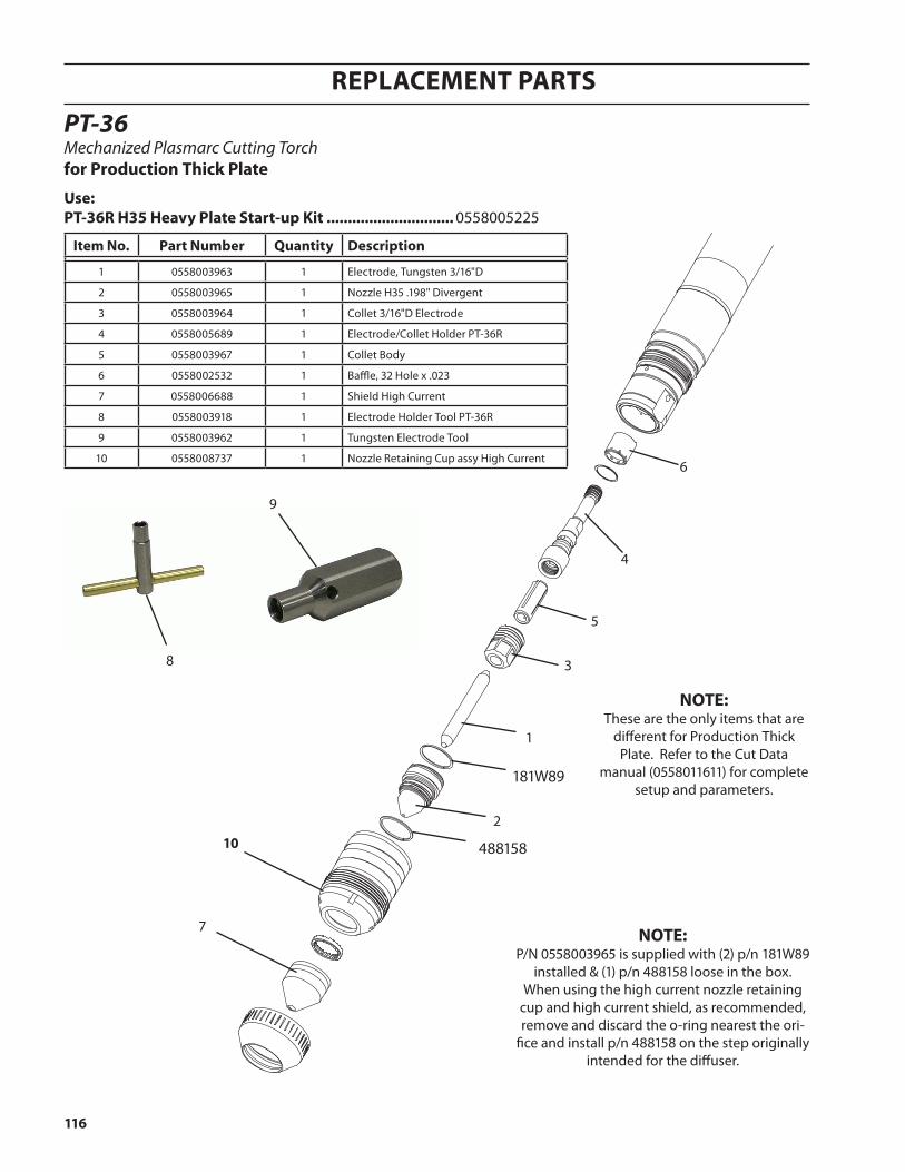
116
Replacement paRts
PT-36Mechanized Plasmarc Cutting Torchfor production thick plate
8
9
note:These are the only items that are
different for Production Thick Plate. Refer to the Cut Data
manual (0558011611) for complete setup and parameters.
note:P/N 0558003965 is supplied with (2) p/n 181W89
installed & (1) p/n 488158 loose in the box. When using the high current nozzle retaining
cup and high current shield, as recommended, remove and discard the o-ring nearest the ori-
fice and install p/n 488158 on the step originally intended for the diffuser.
use:pt-36r h35 heavy plate start-up Kit .............................. 0558005225
item no. part number Quantity Description
1 0558003963 1 Electrode, Tungsten 3/16"D
2 0558003965 1 Nozzle H35 .198" Divergent
3 0558003964 1 Collet 3/16"D Electrode
4 0558005689 1 Electrode/Collet Holder PT-36R
5 0558003967 1 Collet Body
6 0558002532 1 Baffle, 32 Hole x .023
7 0558006688 1 Shield High Current
8 0558003918 1 Electrode Holder Tool PT-36R
9 0558003962 1 Tungsten Electrode Tool
10 0558008737 1 Nozzle Retaining Cup assy High Current
181W89
488158
2
1
3
5
4
6
7
10
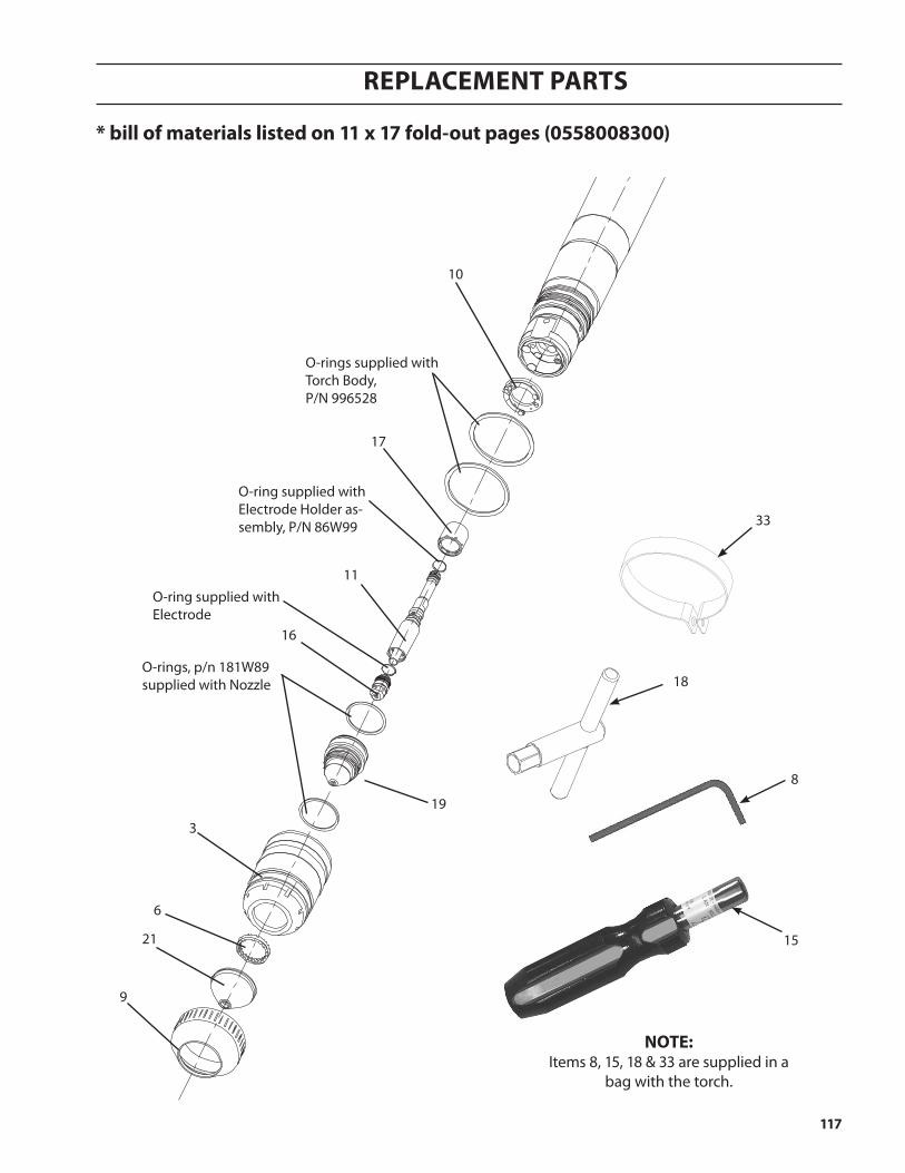
117
Replacement paRts
10
O-rings supplied with Torch Body,P/N 996528
17
O-ring supplied with Electrode Holder as-sembly, P/N 86W99
11
16
19
3
6
21
9
O-ring supplied with Electrode
O-rings, p/n 181W89 supplied with Nozzle
15
18
8
33
note:Items 8, 15, 18 & 33 are supplied in a
bag with the torch.
* bill of materials listed on 11 x 17 fold-out pages (0558008300)

118
Replacement paRts

reVision historY
1. Originally released - 04/20142. revision 06/2014 - removed RAS handle.
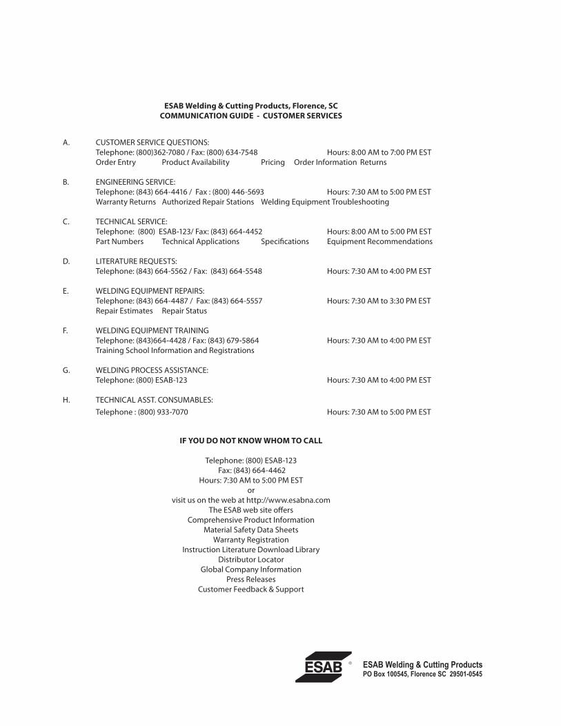
A. CUSTOMER SERVICE QUESTIONS: Telephone: (800)362-7080 / Fax: (800) 634-7548 Hours: 8:00 AM to 7:00 PM EST Order Entry Product Availability Pricing Order Information Returns
B. ENGINEERING SERVICE: Telephone: (843) 664-4416 / Fax : (800) 446-5693 Hours: 7:30 AM to 5:00 PM EST Warranty Returns Authorized Repair Stations Welding Equipment Troubleshooting
C. TECHNICAL SERVICE: Telephone: (800) ESAB-123/ Fax: (843) 664-4452 Hours: 8:00 AM to 5:00 PM EST Part Numbers Technical Applications Specifications Equipment Recommendations
D. LITERATURE REQUESTS: Telephone: (843) 664-5562 / Fax: (843) 664-5548 Hours: 7:30 AM to 4:00 PM EST
E. WELDING EQUIPMENT REPAIRS: Telephone: (843) 664-4487 / Fax: (843) 664-5557 Hours: 7:30 AM to 3:30 PM EST Repair Estimates Repair Status
F. WELDING EQUIPMENT TRAINING Telephone: (843)664-4428 / Fax: (843) 679-5864 Hours: 7:30 AM to 4:00 PM EST Training School Information and Registrations
G. WELDING PROCESS ASSISTANCE: Telephone: (800) ESAB-123 Hours: 7:30 AM to 4:00 PM EST
H. TECHNICAL ASST. CONSUMABLES: Telephone : (800) 933-7070 Hours: 7:30 AM to 5:00 PM EST
if You Do not KnoW Whom to call
Telephone: (800) ESAB-123 Fax: (843) 664-4462
Hours: 7:30 AM to 5:00 PM ESTor
visit us on the web at http://www.esabna.comThe ESAB web site offers
Comprehensive Product InformationMaterial Safety Data Sheets
Warranty RegistrationInstruction Literature Download Library
Distributor LocatorGlobal Company Information
Press ReleasesCustomer Feedback & Support
esaB Welding & cutting products, florence, sccommunication guiDe - customer serVices