Embed Size (px)
Citation preview

integratedsolutions
electromagnetic
short form catalog

Electromagnetic Integrated Solutions
Innovative Solutions from Components to Complex AssembliesUnderstanding how and where potential EMI problems exist inan electronic system can be a daunting challenge. Uncoveringthe best way to address both conducted and radiated EMI byunderstanding all the mechanical, electrical and environmentalconcerns of your system can reduce costs and keep a project on budget and schedule. Our extensive library of standard components, which we frequently develop into custom assemblies, offers you a more complete, high performance solution… saving you time and money.
Industry’s Broadest Line of Standard ProductsWe offer the flexibility to filter EMI at the power source, at the I/Oconnection, in a barrier wall or on the PCB. Our industry-leadingline, including inductors, glass and resin sealed filters, SMT filters, filter plates, filtered connectors, power entry and power line filters, military/aerospace multisection filters and magnetics,gives you a wide range of size, performance and packaging options, most available RoHS compliant. In addition, we’ve gotover 800 standard MIL QPL products and DSCC part numbers.
Custom Application-SpecificSolutionsThis phrase serves as an excellent summary of what we produce for our customers, as well as defines what distinguishes our company from others in the electronics market. Rarely does a 100% off-the-shelf component completelysatisfy the mechanical, electrical, and/or power requirementsand constraints of a sophisticated OEM design. Whether modifyingan existing component, working from a ”clean sheet“ approach,or integrating various technologies into a subassembly or system, the result will be a tailored API Technologies’ SpectrumControl design for your exact application parameters, one thatpushes the envelope of product performance. As the world leader in EMI products and a market leader
in microwave, power and sensor products, our customers relyon us to create and provide optimized solutions that improvetheir competitive advantage.
2
API Technologies has been the world’s leading provider of custom application-specific EMI filter solutions since 1968.Through our Spectrum Control line we offer a wide range ofstandard products and we’ll develop a new or modified productor integrated assembly to help you address the mechanical,electrical and/or power requirements of your next design. Our family of electromagnetic integrated solutions includes not only the industry’s most complete line of coaxial EMI components, power surface mount filters, filtered connectors, filtered arrays, power filters and EMC testing services, but also an expanded offering of ceramic capacitors, power film capacitors, filtered and unfiltered interconnects, and magnetics.
Table of Contents:EMI Filter Solutions . . . . . . . . . . . . . . . . . . . . 2-3
Integration, Global & Technical Resources . . . . . . . . . . . . . . . . . . . 4-5
Product Applications . . . . . . . . . . . . . . . . . . . 6-7
EMC Test Capabilities . . . . . . . . . . . . . . . . . . 8-9
Ceramic Capacitors . . . . . . . . . . . . . . . . . . 10-16
Coaxial Filters & Interconnects
Surface Mount EMI Filters . . . . . . . . . . 17-21
Low Pass EMI Filters . . . . . . . . . . . . . . 22-29
EMI Filtered Arrays . . . . . . . . . . . . . . . . 30-36
EMI Filtered Connectors. . . . . . . . . . . . 37-45
QuietShield Caskets & Shielding . . . . 46-47
Specialty Connectors & Custom Cable Assemblies. . . . . . . . . . . 48-53
Power Filters & Film Capacitors . . . . . . . . 54-66
Magnetics . . . . . . . . . . . . . . . . . . . . . . . . . . 67-69
PDF LinkingThe table of contents on page 2 and in each product section is linked to ease your navigation within this PDF. In addition, on each productpage the API Technologies’ Spectrum Control logo will return you to page 2 and the tab will return you to that section’s table of contents.

3
Coaxial Filters & Interconnects• Resin and hermetically sealed filters
• Motor-line feed-through filters (MLFT)
• High current/high voltage filters
• Miniature hermetically sealed and surface mount filters
• Filter plates and terminal blocks
• D-sub and combo filtered connectors
• Ribbon and datacomm connectors
• Rugged USB connectors
Power Filters & Film Modules• Commercial power filters
• Military/aerospace power filters
• Power entry modules
• Film feed-through filters
• Film modules
Magnetics• Current transformers
• Power transformers
• Inductors, chokes and filters
• Switch mode power supply inductors
• Modem and module transformers
• Air coils
Ceramic Capacitors• Capacitor arrays
• SMPS modular capacitors
• Planar capacitors
• Discoidal and tubular capacitors
Specialty Connectors & Custom Cable Assemblies• Circular connectors
• Mini-MIL and Rapid Mate connectors
• Audio and glass sealed connectors
• Value-added terminationsand harnesses
• Custom cable assemblies
Product Families

Low CostManufacturing CentersISO9001:2008 certified API Technologies adheres to world classmanufacturing techniques ensuring each customer receives theSix Sigma reliability they demand. In response to the realities of the marketplace, we have established low cost manufacturing facilities in China and Mexico. These new plants complement ourNorth American production capacity and flexible manufacturingsystems, allowing us to ramp-up production to meet fast-track delivery requirements.
Global ReachToday, more than ever, it is imperative suppliers be prepared tosupport their customers around the world. API Technologies hascreated a network of sales and design centers, manufacturingplants and distribution facilities to support the world’s major markets. From field sales specialists to engineering and manufacturing to logistics, we have moved our key program development personnel closer to our customers regardless of their location. We are committed to being a player in the globaleconomy and ideal partner for our worldwide OEM customers.
VerticalIntegrationOur business teams coordinate and share extensive in-house resources to support many of the problem-solving designs and value-added programs we create.Internal capabilities range from formulating and producing the ceramics used in many of our productsto complete metal fabrication, which facilitates the mechanical/packaging requirements of our customers’designs. Specific technologies are sourced from multiple locations using expertise found throughout our organization, often crossing business segments tofind the ideal production method, including use of ourMIL-STD-790 and TS16949 certified factories.
4

An Engineering & Technology LeaderThe heritage of our company, dating to its founding in 1968, is as an engineering driven, solutions provider. Through the years of expansion and acquisition, this basic premise remains a constant and driving force. Our teams of experiencedapplication engineers use sophisticated simulation software to replicate real-world environments. Once product designs are complete, we conduct exhaustive in-house testing and verification to ensure function and compliance. API Technologiesmaintains a leadership position in many industries by applyingthe latest technology to design performance-enhancing products and systems.
R & D Commitment...Creating the Next GenerationThe surest way to guarantee organic new product development is through investment in research personnel and equipment. API Technologies consistently commits the resources necessary to fund the innovation and creativity leading to technological advancements. We constantly are looking for ways to improve existing designs, as well as find entirely new approaches yielding unforeseen benefits. All of our business units havemade significant new product introductions in recent years.
5

6
Defense• Specialty Connectors
• QPL’d Coaxial Filters
• Military Custom Power Filters
• Ceramic Capacitors
• Magnetics
Communications• Coaxial Interconnects
• Commercial Custom Power Filters
• Surface Mount Filters
• Magnetics
Avionics• Specialty Connectors
• Coaxial Filters and Interconnects
• Film Modules
• Custom Power Filters
• Magnetics
7
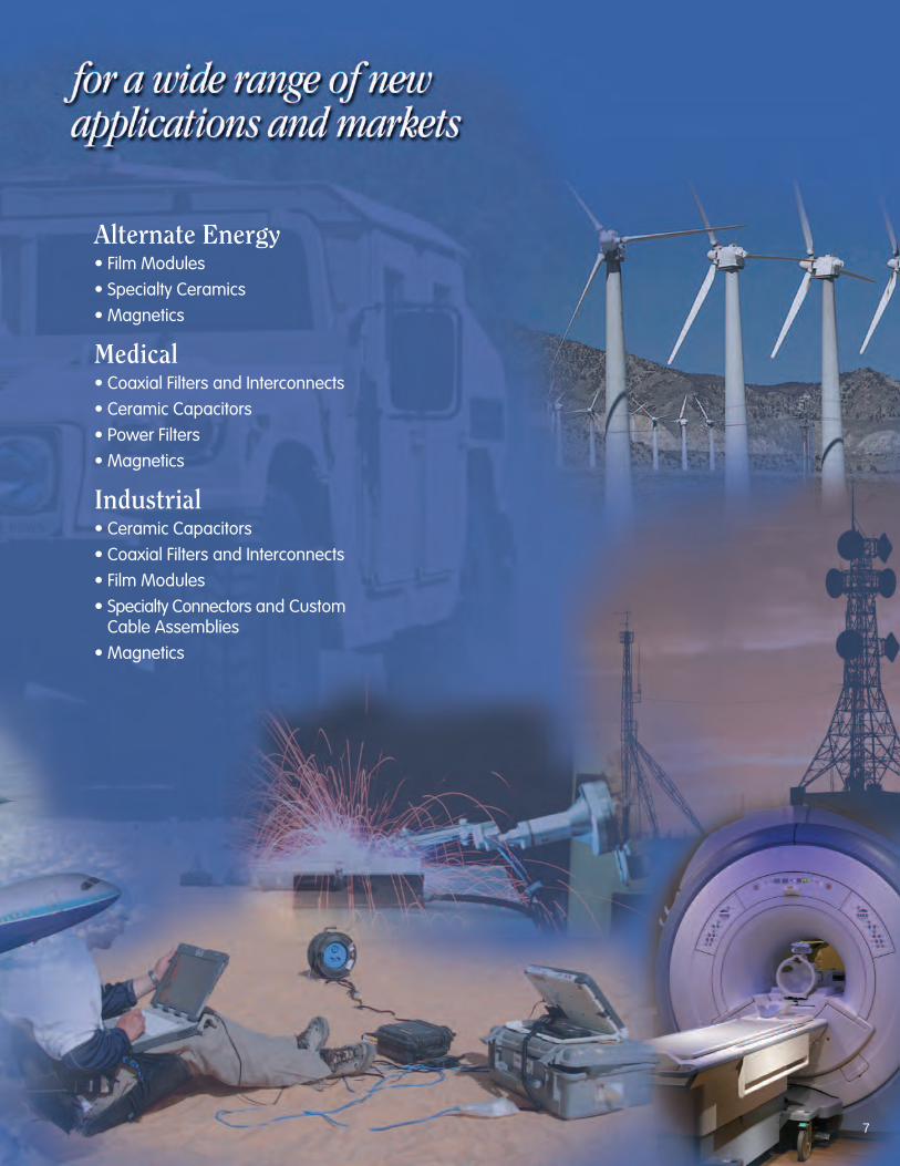
Alternate Energy• Film Modules
• Specialty Ceramics
• Magnetics
Medical• Coaxial Filters and Interconnects
• Ceramic Capacitors
• Power Filters
• Magnetics
Industrial• Ceramic Capacitors
• Coaxial Filters and Interconnects
• Film Modules
• Specialty Connectors and Custom Cable Assemblies
• Magnetics
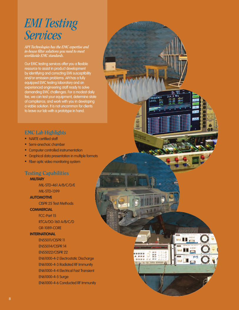
API Technologies has the EMC expertise and in-house filter solutions you need to meet worldwide EMC standards.
Our EMC testing services offer you a flexible resource to assist in product development by identifying and correcting EMI susceptibility and/or emission problems. API has a fully equipped EMC testing laboratory and an experienced engineering staff ready to solve demanding EMC challenges. For a modest daily fee, we can test your equipment, determine state of compliance, and work with you in developing a viable solution. It is not uncommon for clients to leave our lab with a prototype in hand.
EMC Lab Highlights• NARTE certified staff• Semi-anechoic chamber• Computer controlled instrumentation• Graphical data presentation in multiple formats• Fiber optic video monitoring system
Testing CapabilitiesMILITARY
MIL-STD-461 A/B/C/D/E
MIL-STD-1399
AUTOMOTIVE
CISPR 25 Test Methods
COMMERCIAL
FCC-Part 15
RTCA/DO-160 A/B/C/D
GR-1089-CORE
INTERNATIONAL
EN55011/CISPR 11
EN55014/CISPR 14
EN55022/CISPR 22
EN61000-4-2 Electrostatic Discharge
EN61000-4-3 Radiated RF Immunity
EN61000-4-4 Electrical Fast Transient
EN61000-4-5 Surge
EN61000-4-6 Conducted RF Immunity
EMI Testing Services
8

Inspection ClassB
9
Reliability LevelsClass BClass B is outlined in MIL-PRF-28861 and is prescribedfor most military/aerospace requirements. It is more stringent than MIL-PRF-15733, requiring 100% screening that includes thermal shock, voltage conditioning and x-ray.Periodic Group B testing is performed on units selected at random from production lots.
“R” level testing“R” level screening is performed by API Technologies’ Hi-RelLaboratory as detailed below. Customers requiring specialtests may order to their own specifications or simply order to level R and then note additions or deviations.
“R” level test sequence(100% testing unless otherwise specified)
• Thermal Shock: 5 cycles from -55°C to +125°C in accordance with MIL-STD-202, Method 107D, Condition A.
• Burn-in: 100 hours at 1.4x rated DC voltage, 125°C.
• Seal Test: MIL-STD-202, Method 112, Test Condition A. Hermetic sealed parts only.
• Capacitance and Dissipation Factor: MIL-STD-202, Method 305, frequency 1kHz.
• Dielectric Withstanding Voltage: 2.5 times the rated DC voltage for 5 ±1 second at 25°C, with 50 mA maximumcharging current.
• Insulation Resistance: MIL-STD-202, Method 302, 125°C atrated DC voltage and room temperature (25°C). The 125°Crequirement shall be 10% of the specified catalog IR at 25°C.
• DC Resistance: MIL-STD-202, Method 303.
• Insertion Loss Test: Sample per MIL-PRF-15733. At full rated load in accordance with MIL-STD-220. The minimum insertion loss shall be defined in the filter catalog.
• Visual and Mechanical: In accordance with MIL-PRF-15733.
• Marking: All filters which have successfully completed thetest sequence shall be marked with an “R” in the second part of the number. For example, a standard SCI-2130-004becomes SCI-R2130-004 and 9051-100-0000 becomes 9051-R100-0000, and 51-719-011 becomes 51-R719-011 after completion of the Hi-Rel Level “R” Test Sequence.
EMI/RFI Filterand Capacitor Performance Testing
Class B MIL-PRF-28861 Test Sequence Summary
Group I
AC voltage drop (when applicable)
Voltage and temperature limits of capacitance
Insertion loss (at temperature)
Barometric pressure (reduced)
Temperature rise
Current overload
Terminal strength
Thermal shock and immersion
Group II
Subgroup 1
Life
Subgroup 2
Resistance to soldering heat
Salt spray (corrosion)
Radiographic inspection
Subgroup 3
Resistance to solvents
Group III
Shock (specified pulse)
Vibration (high frequency)
Moisture resistance
Seal (when applicable)
Radiographic inspection
X
X
X
X
X
X
X
X
X
X
X
X
X
X
X
X
X
X
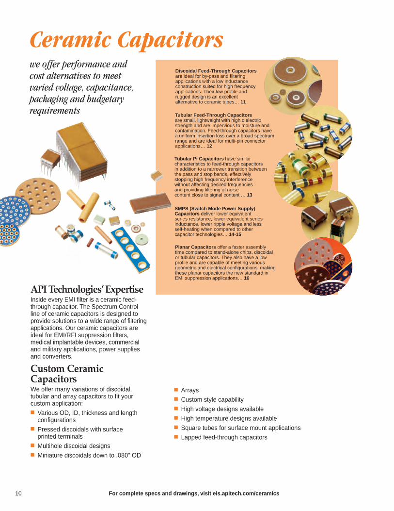
we offer performance and cost alternatives to meet varied voltage, capacitance,packaging and budgetary requirements
Arrays Custom style capability High voltage designs available High temperature designs available Square tubes for surface mount applications Lapped feed-through capacitors
Ceramic Capacitors
SMPS (Switch Mode Power Supply) Capacitors deliver lower equivalent series resistance, lower equivalent seriesinductance, lower ripple voltage and lessself-heating when compared to other capacitor technologies… 14-15
Tubular Pi Capacitors have similar characteristics to feed-through capacitors in addition to a narrower transition betweenthe pass and stop bands, effectively stopping high frequency interference without affecting desired frequencies and providing filtering of noise content close to signal content … 13
Discoidal Feed-Through Capacitorsare ideal for by-pass and filtering applications with a low inductance construction suited for high frequency applications. Their low profile and rugged design is an excellent alternative to ceramic tubes… 11
Tubular Feed-Through Capacitors are small, lightweight with high dielectricstrength and are impervious to moisture and contamination. Feed-through capacitors have a uniform insertion loss over a broad spectrumrange and are ideal for multi-pin connector applications… 12
Planar Capacitors offer a faster assembly time compared to stand-alone chips, discoidal or tubular capacitors. They also have a low profile and are capable of meeting various geometric and electrical configurations, makingthese planar capacitors the new standard inEMI suppression applications… 16
API Technologies’ExpertiseInside every EMI filter is a ceramic feed-through capacitor. The Spectrum Control line of ceramic capacitors is designed to provide solutions to a wide range of filteringapplications. Our ceramic capacitors areideal for EMI/RFI suppression filters, medical implantable devices, commercialand military applications, power supplies and converters.
Custom Ceramic CapacitorsWe offer many variations of discoidal, tubular and array capacitors to fit your custom application: Various OD, ID, thickness and length configurations
Pressed discoidals with surface printed terminals
Multihole discoidal designs Miniature discoidals down to .080" OD
For complete specs and drawings, visit eis.apitech.com/ceramics10

For complete specs and drawings, visit eis.apitech.com/discoidal
Discoidal Capacitors
Ceramic discoidal feed-through capacitors are the building blocks of the EMI filter industry. API’s SpectrumControl discoidal capacitors provide great versatility inmeeting varied voltage, capacitance and dimensional requirements. Our nonpolar, multilayer capacitors are small, reliable and high in dielectric strength. Operationaltemperatures of -55°C to +125°C are achieved with no voltage de-rating.
The versatile nature of our discoidals makes them ideally suited for by-pass and filtering applications. Due totheir low inductance construction, these capacitors perform extremely well in high frequency applications. The circulargeometry of a discoidal feed-through capacitor offers manypaths to ground, resulting in lower impedance and better filtering performance.
The low profile and rugged design of our discoidal capacitors offer an excellent alternative to ceramic tubes.
Features NPO, X7R and Z5U ceramics
Excellent high frequency performance
Low profile design
Rugged construction
Low impedance, many paths to ground
Low inductance, nonpolar
AC applications up to 240V
DC applications up to 500V
-55°C to +125°C operation
70
60
50
40
30
20
10
0
Insertion Loss (db) Per MIL-STD-220Curve 1 2 3 4 5
6
7
8
9
10
100010010101010
Frequency (MHz)
1000
pF2700
pF
5000
pF
01uF
027u
F05
6uF
1uF
27uF
56uF
1.4u
F
Typical Insertion Loss - FT Capacitors
11
340 055 A X 145 P 6 B 0
Outer Diameter
Example:
0.340" = 340
Discoidal Part Numbering SystemExample: 340055AX145P6B0The part number shown represents a discoidal with an O.D. of 0.340" and I.D. of 0.055", with a voltage rating of 50 VDC. The ceramic type will be X7R, capacitancevalue is 1,400,000 pF with a tolerance of +100, -0%. The termination will be silver and the parts will receive bulk packaging.
Inner Diameter
Example:
0.055" = 055
VoltageRating
A: 50 VDC
B: 100 VDC
C: 200 VDC
E: 500 VDC
EIA CapCode
Example:
1,400,000 pF= 145
Termination
6: Silver
Packaging
B: Bulk
Special Requirements
0: None
D: Class B
G: Custom
CeramicCode
N: NP0
X: X7R
Z: Z5U
EIA Cap Tolerance
K: ±10%
M: ±20%
P: +100 -0%
Z: +80 -20%
Multilayer Discoidal
Dielectricthickness
Overlaparea
I.D.
Electrodes
Ceramicdielectric
O.D.
Ceram
ic Capacitors
Ceram
ic Capacitors
Tubular Feed-Through (FT) and Pi Capacitors
For complete specs and drawings, visit eis.apitech.com/tubular
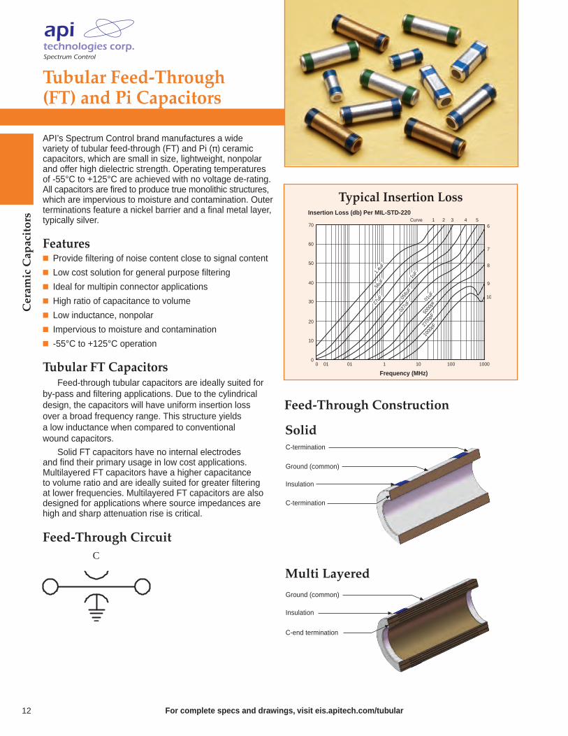
API’s Spectrum Control brand manufactures a wide variety of tubular feed-through (FT) and Pi (π) ceramic capacitors, which are small in size, lightweight, nonpolarand offer high dielectric strength. Operating temperaturesof -55°C to +125°C are achieved with no voltage de-rating.All capacitors are fired to produce true monolithic structures,which are impervious to moisture and contamination. Outerterminations feature a nickel barrier and a final metal layer,typically silver.
Features Provide filtering of noise content close to signal content
Low cost solution for general purpose filtering
Ideal for multipin connector applications
High ratio of capacitance to volume
Low inductance, nonpolar
Impervious to moisture and contamination
-55°C to +125°C operation
Tubular FT CapacitorsFeed-through tubular capacitors are ideally suited for
by-pass and filtering applications. Due to the cylindrical design, the capacitors will have uniform insertion loss over a broad frequency range. This structure yields a low inductance when compared to conventional wound capacitors.
Solid FT capacitors have no internal electrodes and find their primary usage in low cost applications. Multilayered FT capacitors have a higher capacitance to volume ratio and are ideally suited for greater filtering at lower frequencies. Multilayered FT capacitors are alsodesigned for applications where source impedances arehigh and sharp attenuation rise is critical.
C
Feed-Through Circuit
C-termination
Insulation
Ground (common)
C-termination
Ground (common)
Insulation
C-end termination
Solid
Multi Layered
70
60
50
40
30
20
10
0
Insertion Loss (db) Per MIL-STD-220Curve 1 2 3 4 5
6
7
8
9
10
100010010101010
Frequency (MHz)
1000
pF2700
pF
5000
pF
01uF
027u
F05
6uF
1uF
27uF
56uF
1.4u
F
Typical Insertion Loss
Feed-Through Construction
12

Tubular Feed-Through (FT) and Pi Capacitors
Tubular Pi CapacitorsCompared to feed-through tubular capacitors, Pi tubular capacitors have a much narrower transition between the pass and stop bands. Pi capacitors are effective instopping high frequency interference without affecting necessary frequencies immediately below the stop band.
Similar to feed-through tubular capacitors, Pi tubular capacitors can be designed with a solid or multilayeredconfiguration. Solid Pi tubular capacitors are more cost effective, but limited in capacitance values. Multilayered Pi tubular capacitors can cover a wider range of capacitance,while still maintaining the mechanical strength of a solid Pitubular capacitor in a similar case size.
1GHz100 MHz
Frequency10 MHz
T
1 MHz
70
60
50
40
30
20
10
80
Insertion Loss (db)
33000
10000 4000
1000
310
100
Ceram
ic CapacitorsSolid
MultiLayeredTube
Ground "G"
Electrode "E1"
Electrode "E2"
Ground "G"
Electrode "E1"
Electrode "E2"
Buried electrode tube
Pi Construction
C1 C2
Pi Circuit
C1 + C2 = CTotalInductive element not included.
I 81 50 173 X7R 471 M
Tubular Part Numbering SystemExample: I8150173X7R471MThe part number shown represents a Pi tubular capacitorwith an O.D. of 0.081" and I.D. of 0.050", with a voltage of200 VDC. The ceramic type will be X7R, capacitance valueis 470 pF with a tolerance of ±20%. The termination will besilver and the parts will receive bulk packaging.
Outer Diameter
Example:
0.081" = 81
VoltageRating
A: FT, 50 VDC
C: FT, 100 VDC
E: FT, 200 VDC
G: Pi, 50 VDC
H: Pi, 100 VDC
I: Pi, 200 VDC
Inner Diameter
Example:
0.050" = 50
Length
Example:
0.173" = 173
CeramicCode
NP0
X7R
Y5V
EIA Cap Code
Example:
470 pF = 471
EIA Cap Tolerance
M: ±20%
N: ±30%
P: +100 -0%
Z: +80 -20%
Typical Insertion Loss - Pi Capacitors
For complete specs and drawings, visit eis.apitech.com/tubular 13
Mil Qualified & DSCC CertifiedSMPS Capacitor Assemblies
Ceram
ic Capacitors
Dielectric CharacteristicsAPI offers SMPS capacitors in two basic dielectric classes, with individual designs tailored to meet specificperformance characteristics.
Dielectric Type Stability DescriptionClass
BP Ultra Stable Effects on electrical properties are (NPO/COG) Class I minimal with variations in operating
temperature, voltage, frequency or time. Used in applications which require stable performance.
BQ, BR Stable Class II dielectrics will exhibit aand BX Class II predictable shift in performance
characteristics when exposed to variations in temperature, voltage, frequency or time. Selected for applications where blocking,coupling, by-passing and frequency discriminating elements are used. Offers higher capacitance than Class I (COG).
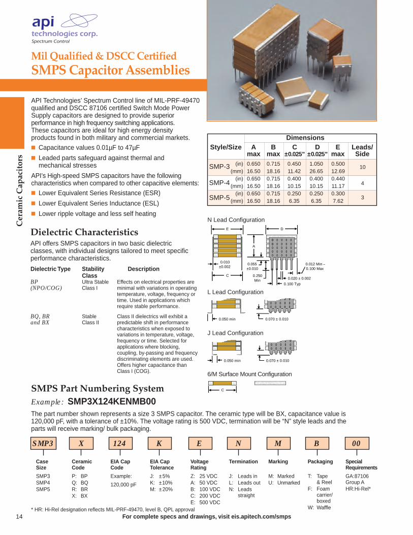
API Technologies’ Spectrum Control line of MIL-PRF-49470qualified and DSCC 87106 certified Switch Mode PowerSupply capacitors are designed to provide superior performance in high frequency switching applications.These capacitors are ideal for high energy density products found in both military and commercial markets. Capacitance values 0.01µF to 47µF
Leaded parts safeguard against thermal and mechanical stresses
API’s High-speed SMPS capacitors have the followingcharacteristics when compared to other capacitive elements: Lower Equivalent Series Resistance (ESR)
Lower Equivalent Series Inductance (ESL)
Lower ripple voltage and less self heating
DimensionsStyle/Size A B C D E Leads/
max max ±0.025" ±0.025" max Side(in) 0.650 0.715 0.450 1.050 0.500
(mm) 16.50 18.16 11.42 26.65 12.69(in) 0.650 0.715 0.400 0.400 0.440
(mm) 16.50 18.16 10.15 10.15 11.17(in) 0.650 0.715 0.250 0.250 0.300
(mm) 16.50 18.16 6.35 6.35 7.62
SMP-3
SMP-4
SMP-5
10
4
3
SMP3 X 124 K E N M B 00
Case Size
SMP3SMP4SMP5
SMPS Part Numbering SystemExample: SMP3X124KENMB00The part number shown represents a size 3 SMPS capacitor. The ceramic type will be BX, capacitance value is 120,000 pF, with a tolerance of ±10%. The voltage rating is 500 VDC, termination will be “N” style leads and the parts will receive marking/ bulk packaging.
CeramicCode
P: BPQ: BQR: BRX: BX
EIA CapCode
Example:
120,000 pF
Termination
J: Leads inL: Leads outN: Leads
straight
Packaging
T: Tape & Reel
F: Foam carrier/boxed
W: Waffle
Special Requirements
GA:87106Group AHR:Hi-Rel*
VoltageRating
Z: 25 VDCA: 50 VDCB: 100 VDCC: 200 VDCE: 500 VDC
EIA Cap Tolerance
J: ±5%K: ±10%M: ±20%
Marking
M: MarkedU: Unmarked
* HR: Hi-Rel designation reflects MIL-PRF-49470, level B, QPL approvalFor complete specs and drawings, visit eis.apitech.com/smps14
0.010±0.002
0.020 ± 0.002
0.100 Typ
0.250Min
0.055±0.010
E D
A
C
0.012 Min –0.100 Max
0.050 min
0.050 min 0.070 ± 0.010
0
N Lead Configuration
J Lead Configuration
L Lead Configuration
C
6/M Surface Mount Configuration
0.070 ± 0.010
For complete specs and drawings, visit eis.apitech.com/smps
Military/Hi-Rel & Commercial/Industrial GradeSMPS Capacitor Assemblies
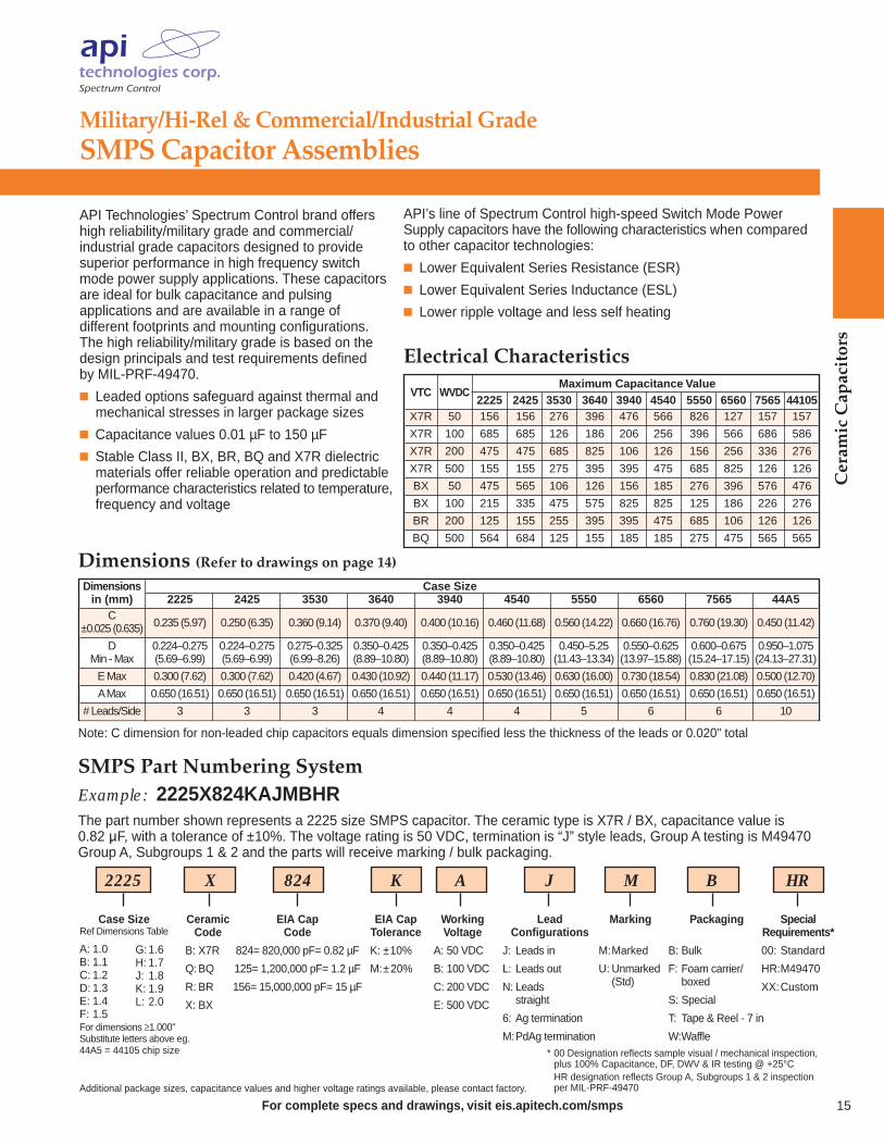
API Technologies’ Spectrum Control brand offershigh reliability/military grade and commercial/industrial grade capacitors designed to provide superior performance in high frequency switchmode power supply applications. These capacitorsare ideal for bulk capacitance and pulsing applications and are available in a range of different footprints and mounting configurations.The high reliability/military grade is based on thedesign principals and test requirements defined by MIL-PRF-49470.
Leaded options safeguard against thermal and mechanical stresses in larger package sizes
Capacitance values 0.01 µF to 150 µF
Stable Class II, BX, BR, BQ and X7R dielectric materials offer reliable operation and predictable performance characteristics related to temperature,frequency and voltage
15
Ceram
ic Capacitors
Electrical Characteristics
API’s line of Spectrum Control high-speed Switch Mode Power Supply capacitors have the following characteristics when comparedto other capacitor technologies:
Lower Equivalent Series Resistance (ESR)
Lower Equivalent Series Inductance (ESL)
Lower ripple voltage and less self heating
Dimensions Case Sizein (mm) 2225 2425 3530 3640 3940 4540 5550 6560 7565 44A5
C0.235 (5.97) 0.250 (6.35) 0.360 (9.14) 0.370 (9.40) 0.400 (10.16) 0.460 (11.68) 0.560 (14.22) 0.660 (16.76) 0.760 (19.30) 0.450 (11.42)±0.025 (0.635)
D 0.224–0.275 0.224–0.275 0.275–0.325 0.350–0.425 0.350–0.425 0.350–0.425 0.450–5.25 0.550–0.625 0.600–0.675 0.950–1.075Min - Max (5.69–6.99) (5.69–6.99) (6.99–8.26) (8.89–10.80) (8.89–10.80) (8.89–10.80) (11.43–13.34) (13.97–15.88) (15.24–17.15) (24.13–27.31)
E Max 0.300 (7.62) 0.300 (7.62) 0.420 (4.67) 0.430 (10.92) 0.440 (11.17) 0.530 (13.46) 0.630 (16.00) 0.730 (18.54) 0.830 (21.08) 0.500 (12.70)
A Max 0.650 (16.51) 0.650 (16.51) 0.650 (16.51) 0.650 (16.51) 0.650 (16.51) 0.650 (16.51) 0.650 (16.51) 0.650 (16.51) 0.650 (16.51) 0.650 (16.51)
# Leads/Side 3 3 3 4 4 4 5 6 6 10
Note: C dimension for non-leaded chip capacitors equals dimension specified less the thickness of the leads or 0.020" total
Dimensions (Refer to drawings on page 14)
2225 X 824 K A J M B HR
Case SizeRef Dimensions Table
A: 1.0B: 1.1C: 1.2D: 1.3E: 1.4F: 1.5
Ceramic Code
B: X7R
Q:BQ
R: BR
X: BX
EIA Cap Code
824= 820,000 pF= 0.82 µF
125= 1,200,000 pF= 1.2 µF
156= 15,000,000 pF= 15 µF
Lead Configurations
J: Leads in
L: Leads out
N: Leads straight
6: Ag termination
M:PdAg termination
Packaging
B: Bulk
F: Foam carrier/boxed
S: Special
T: Tape & Reel - 7 in
W:Waffle
Special Requirements*
00: Standard
HR:M49470
XX:Custom
WorkingVoltage
A: 50 VDC
B: 100 VDC
C: 200 VDC
E: 500 VDC
EIA Cap Tolerance
K: ±10%
M:±20%
Marking
M:Marked
U: Unmarked(Std)
G:1.6H: 1.7J: 1.8K: 1.9L: 2.0
* 00 Designation reflects sample visual / mechanical inspection, plus 100% Capacitance, DF, DWV & IR testing @ +25°CHR designation reflects Group A, Subgroups 1 & 2 inspection per MIL-PRF-49470Additional package sizes, capacitance values and higher voltage ratings available, please contact factory.
SMPS Part Numbering SystemExample: 2225X824KAJMBHRThe part number shown represents a 2225 size SMPS capacitor. The ceramic type is X7R / BX, capacitance value is 0.82 μF, with a tolerance of ±10%. The voltage rating is 50 VDC, termination is “J” style leads, Group A testing is M49470Group A, Subgroups 1 & 2 and the parts will receive marking / bulk packaging.
For dimensions ≥1.000"Substitute letters above eg.44A5 = 44105 chip size
VTC WVDCMaximum Capacitance Value
2225 2425 3530 3640 3940 4540 5550 6560 7565 44105X7R 50 156 156 276 396 476 566 826 127 157 157
X7R 100 685 685 126 186 206 256 396 566 686 586
X7R 200 475 475 685 825 106 126 156 256 336 276
X7R 500 155 155 275 395 395 475 685 825 126 126
BX 50 475 565 106 126 156 185 276 396 576 476
BX 100 215 335 475 575 825 825 125 186 226 276
BR 200 125 155 255 395 395 475 685 106 126 126
BQ 500 564 684 125 155 185 185 275 475 565 565
Ceram
ic Capacitors
For complete specs and drawings, visit eis.apitech.com/planar
PlanarCapacitors
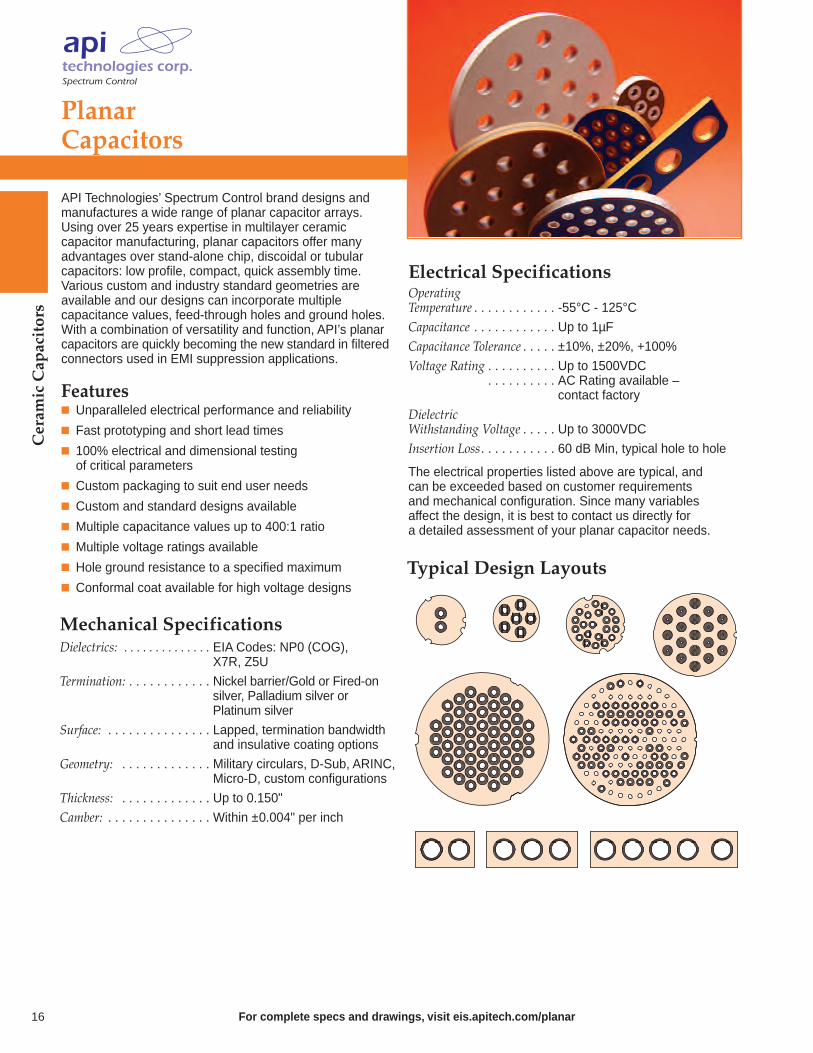
API Technologies’ Spectrum Control brand designs and manufactures a wide range of planar capacitor arrays.Using over 25 years expertise in multilayer ceramic capacitor manufacturing, planar capacitors offer many advantages over stand-alone chip, discoidal or tubular capacitors: low profile, compact, quick assembly time. Various custom and industry standard geometries are available and our designs can incorporate multiple capacitance values, feed-through holes and ground holes.With a combination of versatility and function, API’s planarcapacitors are quickly becoming the new standard in filteredconnectors used in EMI suppression applications.
Features Unparalleled electrical performance and reliability
Fast prototyping and short lead times
100% electrical and dimensional testing of critical parameters
Custom packaging to suit end user needs
Custom and standard designs available
Multiple capacitance values up to 400:1 ratio
Multiple voltage ratings available
Hole ground resistance to a specified maximum
Conformal coat available for high voltage designs
16
Electrical SpecificationsOperatingTemperature . . . . . . . . . . . . -55°C - 125°CCapacitance . . . . . . . . . . . . Up to 1µFCapacitance Tolerance . . . . . ±10%, ±20%, +100%Voltage Rating . . . . . . . . . . Up to 1500VDC
. . . . . . . . . . AC Rating available –
. . . . . . . . . . contact factory
DielectricWithstanding Voltage . . . . . Up to 3000VDCInsertion Loss. . . . . . . . . . . 60 dB Min, typical hole to hole
Mechanical SpecificationsDielectrics: . . . . . . . . . . . . . . EIA Codes: NP0 (COG), . . . . . . . . . . . . . . . . . . . X7R, Z5U
Termination: . . . . . . . . . . . . Nickel barrier/Gold or Fired-on . . . . . . . . . . . . silver, Palladium silver or . . . . . . . . . . . . Platinum silver
Surface: . . . . . . . . . . . . . . . Lapped, termination bandwidth . . . . . . . . . . . . . . . . . . . and insulative coating options
Geometry: . . . . . . . . . . . . . Military circulars, D-Sub, ARINC, . . . . . . . . . . . . . . . . . . . Micro-D, custom configurations
Thickness: . . . . . . . . . . . . . Up to 0.150"Camber: . . . . . . . . . . . . . . . Within ±0.004" per inch
The electrical properties listed above are typical, andcan be exceeded based on customer requirements and mechanical configuration. Since many variables affect the design, it is best to contact us directly for a detailed assessment of your planar capacitor needs.
Typical Design Layouts
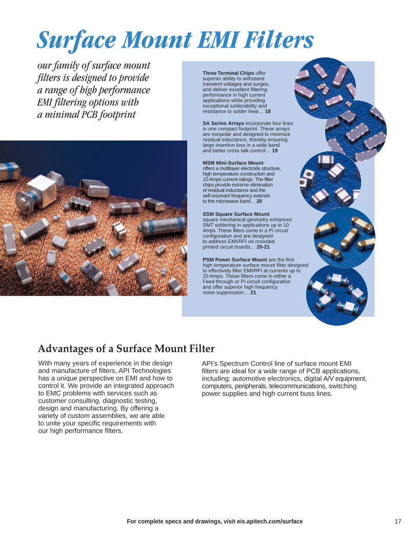
our family of surface mountfilters is designed to provide a range of high performanceEMI filtering options with a minimal PCB footprint
With many years of experience in the designand manufacture of filters, API Technologieshas a unique perspective on EMI and how tocontrol it. We provide an integrated approachto EMC problems with services such as customer consulting, diagnostic testing, design and manufacturing. By offering a variety of custom assemblies, we are able to unite your specific requirements with our high performance filters.
API’s Spectrum Control line of surface mount EMI filters are ideal for a wide range of PCB applications, including: automotive electronics, digital A/V equipment,computers, peripherals, telecommunications, switchingpower supplies and high current buss lines.
Advantages of a Surface Mount Filter
Surface Mount EMI Filters
MSM Mini-Surface Mount offers a multilayer electrode structure, high temperature construction and 10 Amps current ratings. The filter chips provide extreme elimination of residual inductance and the self-resonant frequency extends to the microwave band… 20
SA Series Arrays incorporate four lines in one compact footprint. These arrays are nonpolar and designed to minimize residual inductance, thereby ensuring large insertion loss in a wide band and better cross talk control… 19
PSM Power Surface Mount are the first high temperature surface mount filter designedto effectively filter EMI/RFI at currents up to 20 Amps. These filters come in either a Feed-through or Pi circuit configuration and offer superior high frequency noise suppression… 21
SSM Square Surface Mount square mechanical geometry enhancesSMT soldering in applications up to 10Amps. These filters come in a Pi circuit configuration and are designed to address EMI/RFI on crowded printed circuit boards… 20-21
Three Terminal Chips offer superior ability to withstand transient voltages and surges,and deliver excellent filtering performance in high current applications while providing exceptional solderability and resistance to solder heat… 18
For complete specs and drawings, visit eis.apitech.com/surface 17
Ordering InformationExample: SF0805C221SBNCTThis part number represents a three terminal chip with a body size of 0805 with a COG (NPO) dielectric. The capacitance is 220 pF with a capacitance tolerance of +50%/-20%. Voltage rating is 50 Volts DC. It has nickel barrier, solder plated terminations and a current rating of 0.4 Amp, (400 milliamps). The parts are taped and reeled.
SF 0805 C 221 S B N C T
Style Size Ceramic Capacitance Capacitance Rated Termination Current PackagingCode Tolerance Voltage (Vdc) Rating
SF 0603 C - COG First two S - +50%/-20% A - 25 N - Ni Barrier, B - 0.3 A T - Tape0805 X - X7R numbers are Z - +80%/-20% B - 50 Solder C - 0.4 A & Reel1205 Y - Y5V significant, D - 100 Plated D - 1 A B - Bulk1806 the third E - 2 A
number F - 3 Arefers to G - 4 Anumber of H - 5 Azeroes I - 6 A
For complete specs and drawings, visit eis.apitech.com/3terminal
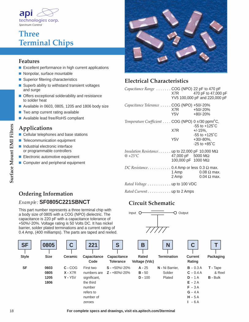
Three Terminal Chips
Features Excellent performance in high current applications Nonpolar, surface mountable Superior filtering characteristics Superb ability to withstand transient voltages and surge
Offers exceptional solderability and resistance to solder heat
Available in 0603, 0805, 1205 and 1806 body size Two amp current rating available Available lead free/RoHS compliant
Applications Cellular telephones and base stations Telecommunication equipment Industrial electronic interface or programmable controllers
Electronic automotive equipment Computer and peripheral equipment
Electrical CharacteristicsCapacitance Range . . . . . . . COG (NPO) 22 pF to 470 pF. . . . . . . . . . . . . . . . . . . . . X7R 470 pF to 47,000 pF. . . . . . . . . . . . . . . . . . . . . YV5 100,000 pF and 220,000 pF
Capacitance Tolerance . . . . . COG (NPO) +50/-20%. . . . . . . . . . . . . . . . . . . . . X7R +50/-20%. . . . . . . . . . . . . . . . . . . . . Y5V +80/-20%
Temperature Coefficient . . . . COG (NPO) 0 ±/30 ppm/˚C,. . . . . . . . . . . . . . . . . . . . . -55 to +125˚C. . . . . . . . . . . . . . . . . . . . . X7R +/-15%, . . . . . . . . . . . . . . . . . . . . . -55 to +125˚C. . . . . . . . . . . . . . . . . . . . . Y5V +30/-80%,. . . . . . . . . . . . . . . . . . -25 to +85˚C
Insulation Resistance . . . . . . up to 22,000 pF 10,000 MΩ@ +25°C . . . . . . . . . . . . . . . 47,000 pF 5000 MΩ. . . . . . . . . . . . . . . . . . . . . 100,000 pF 1000 MΩ
DC Resistance. . . . . . . . . . . 0.4 Amp or less 0.3 Ω max.. . . . . . . . . . . . . . . . . . . . . 1 Amp 0.08 Ω max.. . . . . . . . . . . . . . . . . . . . . 2 Amp 0.04 Ω max.
Rated Voltage . . . . . . . . . . . up to 100 VDC
Rated Current . . . . . . . . . . . up to 2 Amps
OutputInput
Circuit Schematic
18
Surface Mount EMI Filters

Surface Mount EMI Filters
19For complete specs and drawings, visit eis.apitech.com/saseries
SA Series Arrays
Features The filter’s structure minimizes residual inductance with a high self-resonant frequency, ensuring large insertion loss in a wide band.
The common ground electrode built into the chipensures complete grounding of all lines at the ground on both ends. The filter is designed to minimize cross talk.
An optimum constant can be selected from the capacity range of 22-22,000 pF to best suit the frequency.
Solder plated nickel barrier terminations offer good solderability and resistance to soldering heat.
Available lead free/RoHs compliant
Applications Noise reduction for DC lines on computers Computer peripheral equipment Digital TV and VTR Cellular telephones Automotive electronics
Ordering Information
Example: SA1206C22OMBNBThe part number represents a 4-capacitor array with a bodysize of 1206 with a COG (NPO) dielectric. The capacitanceis 22 pF with a capacitance tolerance of ±20%. Voltage rating is 50 VDC. It has nickel barrier, solder plated terminations, and the parts are bulk-packaged.
60
50
40
30
20
0.1 1 10 100 1000 10000
Frequency (MHz)
Inse
rtio
n Lo
ss (d
B)
70
10
0
22000
22001000
470
2247
100
220
GND
Circuit Schematic
Typical Insertion Loss
TemperatureCharacteristics
C +/- 30 ppm/˚C
R +/- 15%
U -750 +/- 120 ppm/˚C
Style
SA Series
CapacitanceSize
1206
Capacitance toleranceM = ± 20%
Packaging
T - Tape and reel4,000 pc/reel
B - Bulk pack1,000 pcs/bag
22 pF
47 pF
100 pF
220 pF
470 pF
1,000 pF
2,200 pF
22,000 pF
Termination
N = Ni BarrierSolder Plated
Rated Voltage(Vdc)A = 25B = 50
SA 1206 C 220 M B N B
Electrical CharacteristicsRated Voltage . . . . . . . . . . . 25 VDC to 50 VDCRated Current . . . . . . . . . . . 0.3 AmpsIR. . . . . . . . . . . . . . . . . . . . 10,000 MΩ Min.DC Resistance. . . . . . . . . . . 0.3 Ω Max. Temperature Range . . . . . . . -55˚C to +125˚CCapacitance Range . . . . . . . 22 pF to 22,000 pFCapacitance Tolerance . . . . . ±20%
MSM, SSM & PSM Series Filters
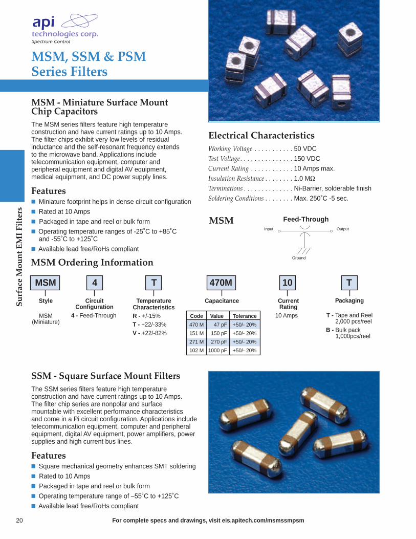
MSM - Miniature Surface Mount Chip CapacitorsThe MSM series filters feature high temperature construction and have current ratings up to 10 Amps. The filter chips exhibit very low levels of residual inductance and the self-resonant frequency extends to the microwave band. Applications include telecommunication equipment, computer and peripheral equipment and digital AV equipment, medical equipment, and DC power supply lines.
Features Miniature footprint helps in dense circuit configuration Rated at 10 Amps Packaged in tape and reel or bulk form Operating temperature ranges of -25˚C to +85˚C and -55˚C to +125˚C
Available lead free/RoHs compliant
MSMOutputInput
Ground
Feed-Through
MSM Ordering Information
MSM 4 T 470M 10 T
Style
MSM(Miniature)
CapacitanceCircuitConfiguration
4 - Feed-Through
CurrentRating10 AmpsValue
47 pF
150 pF
270 pF
1000 pF
Tolerance
+50/- 20%
+50/- 20%
+50/- 20%
+50/- 20%
Code
470 M
151 M
271 M
102 M
Packaging
T - Tape and Reel 2,000 pcs/reel
B - Bulk pack1,000pcs/reel
TemperatureCharacteristicsR - +/-15%T - +22/-33%V - +22/-82%
SSM - Square Surface Mount FiltersThe SSM series filters feature high temperature construction and have current ratings up to 10 Amps. The filter chip series are nonpolar and surface mountable with excellent performance characteristics and come in a Pi circuit configuration. Applications includetelecommunication equipment, computer and peripheralequipment, digital AV equipment, power amplifiers, powersupplies and high current bus lines.
Features Square mechanical geometry enhances SMT soldering Rated to 10 Amps Packaged in tape and reel or bulk form Operating temperature range of –55˚C to +125˚C Available lead free/RoHs compliant
For complete specs and drawings, visit eis.apitech.com/msmssmpsm20
Electrical CharacteristicsWorking Voltage . . . . . . . . . . . 50 VDCTest Voltage. . . . . . . . . . . . . . . 150 VDCCurrent Rating . . . . . . . . . . . . 10 Amps max.Insulation Resistance . . . . . . . . 1.0 MΩ Terminations . . . . . . . . . . . . . . Ni-Barrier, solderable finishSoldering Conditions . . . . . . . . Max. 250˚C -5 sec.
Surface Mount EMI Filters
Surface Mount EMI Filters
MSM, SSM & PSM Series Filters
OutputInput
Ground
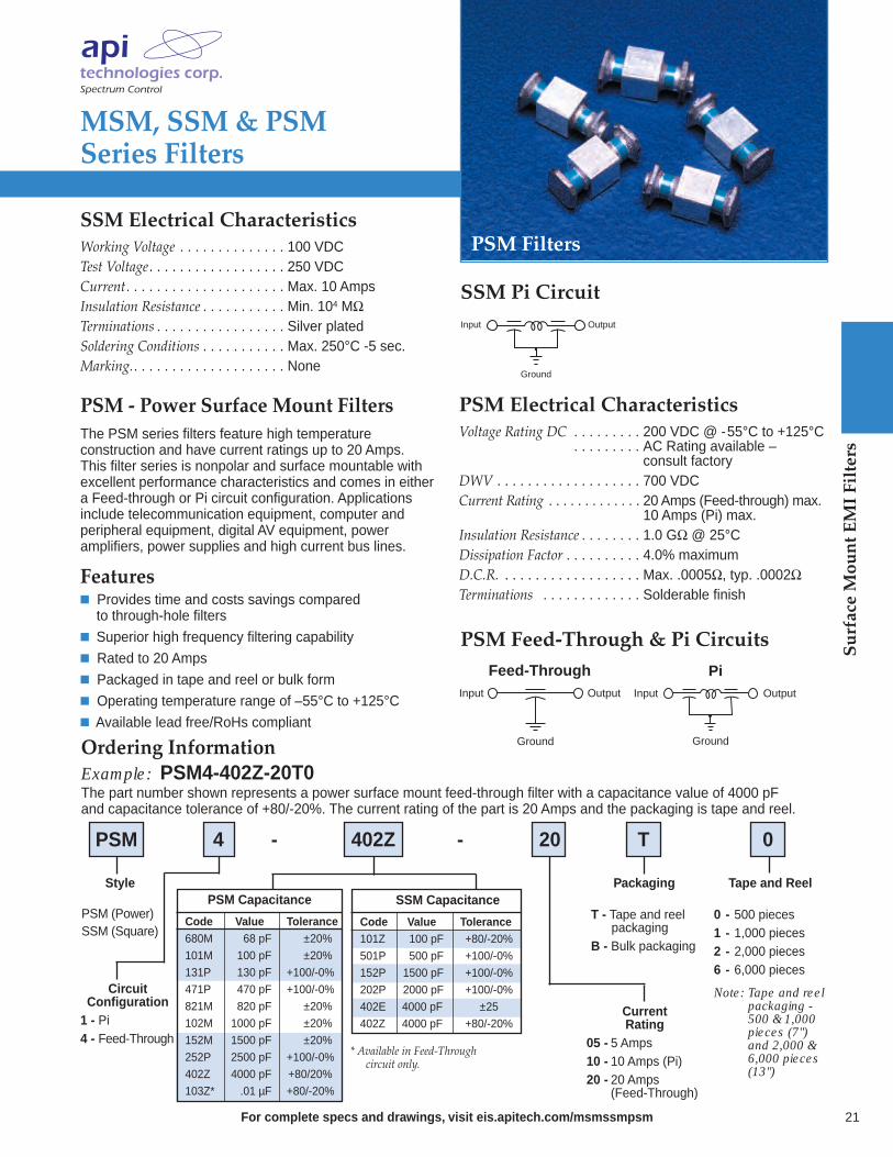
SSM Electrical CharacteristicsWorking Voltage . . . . . . . . . . . . . . 100 VDCTest Voltage. . . . . . . . . . . . . . . . . . 250 VDCCurrent. . . . . . . . . . . . . . . . . . . . . Max. 10 AmpsInsulation Resistance . . . . . . . . . . . Min. 104 MΩTerminations . . . . . . . . . . . . . . . . . Silver platedSoldering Conditions . . . . . . . . . . . Max. 250°C -5 sec.Marking.. . . . . . . . . . . . . . . . . . . . None
PSM - Power Surface Mount FiltersThe PSM series filters feature high temperature construction and have current ratings up to 20 Amps. This filter series is nonpolar and surface mountable withexcellent performance characteristics and comes in either a Feed-through or Pi circuit configuration. Applications include telecommunication equipment, computer and peripheral equipment, digital AV equipment, power amplifiers, power supplies and high current bus lines.
Features Provides time and costs savings compared to through-hole filters
Superior high frequency filtering capability Rated to 20 Amps Packaged in tape and reel or bulk form Operating temperature range of –55°C to +125°C Available lead free/RoHs compliant
SSM Pi Circuit
OutputInput
Ground
OutputInput
Ground
PiFeed-Through
PSM Feed-Through & Pi Circuits
21For complete specs and drawings, visit eis.apitech.com/msmssmpsm
PSM Filters
Ordering InformationExample: PSM4-402Z-20T0The part number shown represents a power surface mount feed-through filter with a capacitance value of 4000 pF and capacitance tolerance of +80/-20%. The current rating of the part is 20 Amps and the packaging is tape and reel.
* Available in Feed-Through circuit only.
Code680M
101M
131P
471P
821M
102M
152M
252P
402Z
103Z*
PSM 4 - 402Z - 20 T 0
Style
PSM (Power)SSM (Square)
PSM Capacitance
CircuitConfiguration1 - Pi4 - Feed-Through
Current Rating
05 - 5 Amps 10 - 10 Amps (Pi)20 - 20 Amps
(Feed-Through)
Packaging
T - Tape and reelpackaging
B - Bulk packaging
Value68 pF
100 pF
130 pF
470 pF
820 pF
1000 pF
1500 pF
2500 pF
4000 pF
.01 µF
Tolerance±20%
±20%
+100/-0%
+100/-0%
±20%
±20%
±20%
+100/-0%
+80/20%
+80/-20%
Tape and Reel
0 - 500 pieces1 - 1,000 pieces2 - 2,000 pieces6 - 6,000 pieces
Note: Tape and reelpackaging - 500 & 1,000 pieces (7") and 2,000 & 6,000 pieces (13")
Code101Z
501P
152P
202P
402E
402Z
SSM Capacitance
Value100 pF
500 pF
1500 pF
2000 pF
4000 pF
4000 pF
Tolerance+80/-20%
+100/-0%
+100/-0%
+100/-0%
±25
+80/-20%
PSM Electrical CharacteristicsVoltage Rating DC . . . . . . . . . 200 VDC @ -55°C to +125°C
. . . . . . . . . AC Rating available –
. . . . . . . . . consult factoryDWV . . . . . . . . . . . . . . . . . . . 700 VDCCurrent Rating . . . . . . . . . . . . . 20 Amps (Feed-through) max.. . . . . . . . . . . . . . . . . . . . . . . 10 Amps (Pi) max.Insulation Resistance . . . . . . . . 1.0 GΩ @ 25°CDissipation Factor . . . . . . . . . . 4.0% maximumD.C.R. . . . . . . . . . . . . . . . . . . Max. .0005Ω, typ. .0002ΩTerminations . . . . . . . . . . . . . Solderable finish

the industry’s most completeline of EMI filters gives youmore style, size, IL performanceand cost alternatives
API Technologies’ Spectrum Control brandwas founded in 1968 as a designer and manufacturer of Electromagnetic Interference(EMI) filters. These many years of experiencehave yielded an engineering-driven team that understands how and where potentialEMI problems exist in an electronic systemand how to best eliminate them. With an extensive library of standard products and a willingness to develop an application-specificcustom solution, our customers count on usto help them satisfy global EMC standardswhile meeting demanding design parameters.
Wide range of package sizes, mounting options and circuit configurations offering maximum design flexibility
Develop custom application-specific solutions addressingyour mechanical and electrical requirements
High reliability construction… built in accordance to MIL-PRF-15733 or MIL-PRF-28861
Over 800 standard QPL products and DSCC part numbers Effective filtering up to 18 GHz Reliability testing available for customer specific requirements
Low Pass EMI Advantages
Low Pass EMI Filters
Resin Sealed Filters provide excellent environmental protection in a rugged case that is resin sealed at both ends and easilymounted with a tapped hole or through hole.These filters are provided in C, L and Pi configu-rations with metric threading available… 26
Spec Spin Filters are an excellent choicefor applications that require many lines tobe filtered in close proximity to each otherdue to their space saving #2-56 threadedminiature EMI spanner design. These filters are designed without a hex and donot require soldering for installation… 25
9925 Series Filters have a knurled design allowing them to be pressed into place creating a reliable mechanical bond making them an excellent choice for applications where soldering is undesirable… 25
High Current Resin Sealed Filters are ideal foruse in high current 5 volt logic buss, as well as±48 VDC telephone rack buss, high currentswitch mode power supplies and DC chargingsystems. These filters feature rugged bolt-instyle for easy installation… 27
Value Added Assemblies offer flexible solutions by allowing you to add connectors, modify terminations or add wire harnesses, therebylowering your cost of acquisition and assembly, reducing your production time/costs and inventory,all while giving you a filter assembly that meetsyour unique design challenges… 29
Hermetically Sealed Filters feature hermeticglass seals and high EMI filtering performancemaking them highly reliable in the toughest environmental conditions. These filters areavailable with C, L, Pi, T and double T configurations with MIL-F-15733 and MIL-F-28861 QPL filters available… 28
Motor Line Feed-Through (MLFT) Filters arehigh capacitance filters specifically designed forDC motor and other lower voltage applications.This one-component solution addresses EMInoise issues and eliminates the need for multiplecomponents and electrical connections… 23
Solder-In Filters offer an ideal solution for applicationsin critical areas where space does not allow for use of mounting tools or hardware. Available in C, Pi andstandard L circuit configurations and primarily used infiltering signal/data lines and AC power lines… 24
For complete specs and drawings, visit eis.apitech.com/lowpass22

Motor Line Feed-Through(MLFT) Filters (Patent Pending)
For complete specs and drawings, visit eis.apitech.com/mlft 23
As the world leader in EMC, API Technologies’ Spectrum Control brand has developed a family of high capacitance filters specifically designed for DCmotor and other lower voltage applications. The MotorLine Feed-Through (MLFT) filter is a one-component solution that eliminates the need for multiple capacitors,inductive coils, leads and PCB assemblies requiring numerous electrical connections and large amounts of space. MLFT filters (patent pending) are engineeredto provide the required EMI filtering and mechanical interface at a reduced cost.MLFT filters offer significant insertion loss to pass
global conductive and radiated EMC tests, such asCISPR 25. Our standard line of filters can be designedinto mechanical packages for easy retrofit into existingdesigns or as custom assemblies to simplify installationduring production. These filters are available in stampedor threaded housings, with single or dual lines, andround leads or Faston terminals for applications to 100 volts.
Benefits Easy installation, provides a connector interface Excellent EMI filtering through GHz range Competitive cost Space saving EMI solution Fewer electrical connections Failsafe DC open circuit for safety concerns Standard and custom filtering and mechanical packages
Transient voltage and surge protection available
Ordering Information
Example: MLFT2-001-TFCACThe part number shown represents a single line, threaded MLFT Filter with Faston Terminals, a capacitance rating of 0.20 µF and a voltage rating of 100V.
Style
T = Single linethreadedS = Single linestampedD = Dual linestamped
Motor Line Feed-Through Filter
Voltage Rating
C = 100V
Terminal
F = .110 FastonR = .062round lead
Capacitance
CA = .20 µFCC = 2000 pFCD = 20 pF
MLFT2 - 001 - T F CA C
Low
Pass EMI Filters
Low
Pass EMI Filters
For complete specs and drawings, visit eis.apitech.com/solder-in24
Solder-In Filters
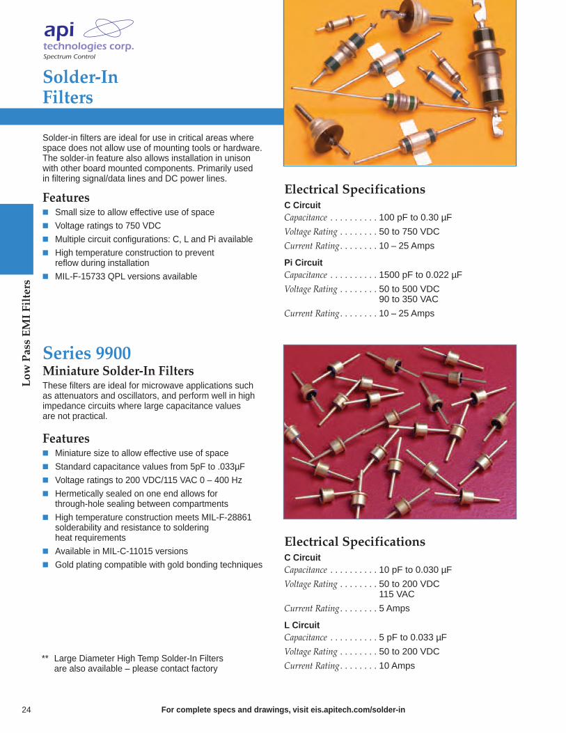
Solder-in filters are ideal for use in critical areas where space does not allow use of mounting tools or hardware.The solder-in feature also allows installation in unison with other board mounted components. Primarily used in filtering signal/data lines and DC power lines.
Features Small size to allow effective use of space Voltage ratings to 750 VDC Multiple circuit configurations: C, L and Pi available High temperature construction to prevent reflow during installation
MIL-F-15733 QPL versions available
Electrical SpecificationsC CircuitCapacitance . . . . . . . . . . 100 pF to 0.30 µF
Voltage Rating . . . . . . . . 50 to 750 VDC
Current Rating. . . . . . . . 10 – 25 Amps
Pi CircuitCapacitance . . . . . . . . . . 1500 pF to 0.022 µF
Voltage Rating . . . . . . . . 50 to 500 VDC. . . . . . . . . . . . . . . . . . 90 to 350 VAC
Current Rating. . . . . . . . 10 – 25 Amps
Miniature Solder-In FiltersThese filters are ideal for microwave applications such as attenuators and oscillators, and perform well in high impedance circuits where large capacitance values are not practical.
Features Miniature size to allow effective use of space Standard capacitance values from 5pF to .033µF Voltage ratings to 200 VDC/115 VAC 0 – 400 Hz Hermetically sealed on one end allows for through-hole sealing between compartments
High temperature construction meets MIL-F-28861 solderability and resistance to soldering heat requirements
Available in MIL-C-11015 versions Gold plating compatible with gold bonding techniques
Electrical SpecificationsC CircuitCapacitance . . . . . . . . . . 10 pF to 0.030 µF
Voltage Rating . . . . . . . . 50 to 200 VDC. . . . . . . . . . . . . . . . . . 115 VAC
Current Rating. . . . . . . . 5 Amps
L CircuitCapacitance . . . . . . . . . . 5 pF to 0.033 µF
Voltage Rating . . . . . . . . 50 to 200 VDC
Current Rating. . . . . . . . 10 Amps
Series 9900
** Large Diameter High Temp Solder-In Filters are also available – please contact factory

Series 9925 Mini-Press Filters
For complete specs and drawings, visit eis.apitech.com/9900 25
This new knurled filter is designed to be pressed into placeand creates a reliable mechanical bond. This feature makesit an excellent selection for applications where soldering isundesirable. Suitable plating is available that allows goldbonding to the terminals.
These filters are ideal for microwave and RF applicationssuch as attenuators, synthesizers and oscillators. They perform well in high impedance circuits where large capacitance values are not practical.
Mechanical SpecificationsInstallation. . . . . . . . . . . Press-in
Plating. . . . . . . . . . . . . . Gold
Seal . . . . . . . . . . . . . . . . Glass sealed on one end, . . . . . . . . . . . . . . . . . . . resin sealed on the other end
Termination Options . . . . Plating suitable for gold bonding
Operating Temperature . . -55°C to +125°C
Electrical SpecificationsCapacitance . . . . . . . . . . 10 pF to 0.030 µF
Voltage Rating . . . . . . . . 50 to 200 VDC
Current Rating. . . . . . . . 5 Amps
Series 54-874-XXXSpec Spin FiltersAPI Technologies’ Spectrum Control brand has developed a space saving #2-56 threaded miniature EMI spanner filter.This new threaded filter is designed without a hex and doesnot require soldering for installation. These features make it an excellent selection for applications that require manylines to be filtered in close proximity. The easy swap outalso allows for flexibility in filter replacement and capacitancesubstitution. Easy filter substitution also allows for flexibilityin filter placement. Custom design queries are always welcome.API’s Spectrum Control brand spanner filter offers
superior insertion loss over a broad frequency range whencompared to surface mount components. The filter is available in capacitance values up to 10,000 pF, and is featured in a microcircuit package used in microwave applications such as frequency synthesizers, power amplifiers, MMW radio, and is ideal for commercial and high-reliability applications.
Mechanical SpecificationsCenter Spacing . . . . . . . . 0.110"
Lead Finish . . . . . . . . . . Gold
Bushing Finish . . . . . . . . Gold
Tightening Torque. . . . . . 16 oz-in (± 2) (0.11 Nm)Electrical SpecificationsCapacitance . . . . . . . . . . 10 pF to 0.010 µF
Voltage Rating . . . . . . . . 50 VDC
Current Rating. . . . . . . . 5 Amps Insertion Tool
Low
Pass EMI Filters

Low
Pass EMI Filters
For complete specs and drawings, visit eis.apitech.com/resin26
Resin Sealed Bolt-In Filters
These filters are easily mounted in a tapped hole or through-hole with supplied nut and lock-washer. Therugged case with resin seals at both ends provides excellent environmental protection. Primarily used in filtering signal/data lines and DC power lines.
Features MIL-PRF-15733 QPL filters available Metric threaded filters available, consult factory RoHS compliancy available
Lead Options Available Straight Turret (nail head) Hooked Bends Flattened Flattened and notched Value added wires Many custom options
Lead Finish Silver Tin/lead Gold - suitable for gold bonding
Electrical SpecificationsC CircuitCapacitance . . . . . . . . . . 10 pF to 1.0 µF
Voltage Rating . . . . . . . . 50 to 500 VDC. . . . . . . . . . . . . . . . . . 115 VAC
Current Rating. . . . . . . . 3 – 25 Amps
L CircuitCapacitance . . . . . . . . . . 10 pF to 1.0 µF
Voltage Rating . . . . . . . . 50 to 500 VDC. . . . . . . . . . . . . . . . . . 115 VAC
Current Rating. . . . . . . . 3 – 25 Amps
Pi CircuitCapacitance . . . . . . . . . . 65 pF to 0.15 µF
Voltage Rating . . . . . . . . 50 to 700 VDC. . . . . . . . . . . . . . . . . . 350 VAC
Current Rating. . . . . . . . 3 – 25 Amps
Thread Sizes Circuits4 - 40 C, L & Pi
6 - 32 C, L & Pi
6 - 40 Pi
8 - 32 C, L & Pi
10 - 32 C & Pi
12 - 28 C & Pi
12 - 32 C & Pi
5/16 - 24 C & Pi
5/16 - 32 C & Pi

High Current/High VoltageResin Sealed Filters
For complete specs and drawings, visit eis.apitech.com/hchvresin 27
High current filters are ideal for use in high current 5 voltlogic buss, but also can be used for ±48 VDC telephonerack buss, high current switch mode power supplies and DC charging systems. High voltage filters find use in high voltage power supplies and applications requiring U.L. Hi-Pot.
Features Current ratings up to 100 Amps Continuous voltage ratings up to 1250 VDC/240 VAC (400Hz)
U.L. 1459 recognized and CSA C22.2 approved versions available
Rugged bolt-in style for easy installation Available in C and Pi circuits
Installation Notes1.Mounting installation torqueMethod A: Mounting in full threaded through holeMaximum torque: 96 in-lbs
Method B: Mounting w/hardwareMaximum torque: 84 in-lbs
2.Terminal installation torqueMaximum torque: 20 in-lbs
Note: Use two-wrench method to install terminal hardware.
30
30
30
30
—
7
—
—
—
—
40
40
40
40
12
20
—
10
6
5
50
50
50
50
20
25
10
22
20
15
50
50
50
50
30
35
20
32
30
50
50
50
50
50
33
40
28
35
35
50
Minimum Insertion Loss (dB)
60
60
200
200
600
600
750
750
1250
2500
Rated Voltage 125°C I
AmpMinCap
10MHzPart Number
Also available through API’s authorized distributors.€ Also available through API’s authorized European distributors/agents.* Denotes parts that are UL recognized to UL 1459 and certified to CSA C22.2**Denotes parts that meet 1500 VAC Dielectric Withstanding Voltage per UL 1283 and CSA C22.2*** AC Voltage to be 400Hz
54-848-005*
54-853-001*
54-853-004 €
54-848-008
54-844-001**
54-844-002**
54-763-008
54-763-009
54-789-003
1280-060 €
DC30MHz
100MHz
300MHz
1GHz
10GHz
3MHz
50
50
100
100
25
25
25
25
25
25
0.22 µF
0.22 µF
0.22 µF
0.22 µF
4700 pF ± 20%
0.01 µF ± 20%
1000 pF
4000 pF
4000 pF
1500 pF
50
50
50
50
50
57
28
35
35
50
50
50
50
50
50
57
28
40
35
50
—
—
140
140
240
240
—
—
—
—
AC***20
20
20
20
—
3
—
—
—
—
1MHzCKT
C
C
C
C
C
C
C
C
C
Pi
Ordering Information
Low
Pass EMI Filters

Low
Pass EMI Filters
For complete specs and drawings, visit eis.apitech.com/hermetic28
Hermetically Sealed Threaded Case Filters
This series of filters features hermetic glass seals and highEMI filtering performance. They are excellent for critical applications that demand high reliability in the toughest environmental conditions and provide broad band high performance EMI filtering from 1 KHz up to 10 GHz.
Features MIL-PRF-15733 and MIL-PRF-28861, DSCC 84084 QPL filters available
Popular .375", .410" and .690" case diameters Voltage ratings from 50 V to 400 VDC/240 AC, 400 Hz Impervious to high moisture environments, solvents and severe environmental conditions
High temperature terminal construction D-slotted bushings High reliability testing available Metric threads available – consult factory
Electrical SpecificationsC CircuitCapacitance . . . . . . . . . . 0.015 µF to 4.0 µF
Voltage Rating . . . . . . . . 50 to 400 VDC. . . . . . . . . . . . . . . . . . 125 – 240 VAC
Current Rating. . . . . . . . 10 – 25 Amps
L CircuitCapacitance . . . . . . . . . . 0.015 µF to 4.0 µF
Voltage Rating . . . . . . . . 50 to 400 VDC. . . . . . . . . . . . . . . . . . 125 to 240 VAC
Current Rating. . . . . . . . 0.08 – 25 Amps
Pi CircuitCapacitance . . . . . . . . . . 0.2 µF to 5.2 µF
Voltage Rating . . . . . . . . 50 to 400 VDC. . . . . . . . . . . . . . . . . . 125 VAC, 240 VAC . . . . . . . . . . . . . . . . . . 0 – 60 Hz
Current Rating. . . . . . . . 0.25 – 20 Amps
Transient Suppression PiCapacitance . . . . . . . . . . 1.4 µF
Voltage Rating . . . . . . . . 5 to 50 VDC. . . . . . . . . . . . . . . . . . 115 VAC, 240 VAC
Current Rating. . . . . . . . 0.5 – 10 Amps
T CircuitCapacitance . . . . . . . . . . 0.15 µF to 1.4 µF
Voltage Rating . . . . . . . . 50 to 400 VDC. . . . . . . . . . . . . . . . . . 115 VAC, 240 VAC
Current Rating. . . . . . . . 0.25 – 20 Amps
TT CircuitCapacitance . . . . . . . . . . 0.5 µF to 1.5 µF
Voltage Rating . . . . . . . . 50 to 300 VDC. . . . . . . . . . . . . . . . . . 125 VAC
Current Rating. . . . . . . . 0.25 – 10 Amps

Value-Added Low Pass Filter Assemblies
For complete specs and drawings, visit eis.apitech.com/valueadd 29
API Technologies’ Spectrum Control line of value-added low pass filters provide flexible solutions to meet your unique design challenges. Our manufacturing process allows you toadd connectors, modify terminations or add wire harnesseswithout adding much cost or drastically increasing lead times.
For custom requirements and exceptional needs,contact our design/manufacturing team.
Our value-added services:• Allow you to stream-line your bill of materials.• Reduce inventory/production costs.• Offer custom application-specific low pass filter assemblies.
Incorporate specific terminations, connectors or wire harnesses to accommodate your application.
Lower the cost of acquisition and assembly.
Reduce production operations and lead times.
Build-to-order low pass filters.
Low
Pass EMI Filters

Provide an EMI filtered signal or powerline between electronic system modules
Reduce cost . . . economical method to meet EMC requirements
Reduce labor . . . eliminate need to assemble filters into a bulkhead
Outperform surface mount EMI filters at frequencies above 50 MHz
Reduce risk of damage to filter elements due to thermal shock and installation
Improve reliability . . . every filter plate is 100% tested for key parameters
Maximize real estate on PCB Mixed schematics in a single filter plate package
Advantages of a Filtered Array
EMI Filtered Arrays
Shrouded Latch Filter Platescombine a bolt-in filter plate withthe latching feature of a ribboncable header providing an easy toinstall and highly effective methodfor an electronic interface andEMI solution in one package… 34
Barrier Strip Filtered Terminal Blocks are available in 2 to 6 terminal versionsand our filter elements provide high insertion loss for EMI/RFI filtering of AC and DC power and control lines…35
Custom Filtered Arrays help meet your design or manufacturing parametersthrough special mechanical and electricalspecifications or by adding varying cablelengths and terminations for a completeturnkey assembly. Custom high reliabilityassemblies available…36
Easy Mate® Filter Plates reduce installation time and overall cost with its patented snap-in design tomaximize real estate on PCBs. TheEasy Mate® Jr. offers a lower profile for installation of feed-through filtersinto small hardware applications…32
Bolt-In Filter Plates provide EMI filtering for signal and power lines and an excellentmethod for electronic system interface. Theseplates eliminate the need to mount filters into bulkheads and are ideal for the isolation of electronic compartments to suppress EMI… 33
For complete specs and drawings, visit eis.apitech.com/array30
our filter plates and terminalblocks provide exceptional EMI protection of signal and power lines at a lower total installed cost

For complete specs and drawings, visit eis.apitech.com/array
Filter Plate Part Numbering System
Filtered Terminal BlockPart Numbering System
31
Example: 52-898-206-BA2The part number shown represents an Easy Mate® filter plate with 2 rows, 6 filters per row. Filters are C style with a capacitance value of 100pF. The plate length is 1.092", and the leads are bent 90° to the right side.
Filter Plates
52 - EasyMate®, EasyMate® Jr. & Bolt-in Style
53 -ShroudedLatch
898Easy Mate®StandardDensity
960Easy Mate®Hi-density
978Easy Mate® Jr. Standard Density
979Easy Mate® Jr. Hi-density
970Bolt-in Standard Density
971Bolt-in Hi-density
038Shrouded Latch
No. ofRows
1 = 1 row2 = 2 rows
Plate Length
Easy Mate®A - 1.092 (27.74mm)B - 1.812 (46.02mm)
Easy Mate® Jr.A - .990 (25.15mm)B - 1.240 (31.49mm)
Bolt-in StyleA - 1.060 (26.92mm)B - 1.560 (39.62mm)C - 2.560 (65.02mm)D - 3.560 (90.42mm)
Latch Height(Shrouded Latch only)
S - Short .435" (11.0mm)L - Long .575" (14.6mm)
Lead Configuration
0 - Straight1 - 90° (left)2 - 90° (right)3 - 90° (both)
Shrouded Latch Configuration
1 - Double Shroud2 - Single Shroud3 - Single Shroud w/90°bend opposite side
Numberof Linesper Row
If less than10, use a 0(zero) first.
FilterDesignation
A - T (Refer toFilter selectiontable online)
No. ofFilters
ConnectionBarrier Strip160 - Front panel mount188 - Rear panel mount257 - AC rated
PCB type227 U.S. pin spacing228 Metric pin spacing
Number of TerminalsBarrier Strip002 - 2 terminals
through006 - 6 terminals
PCB type002 - 2 terminals through012 - 12 terminals
Current Rating
Barrier Strip A - 20 Amps
SizingPCB typeL - Low profile
Special Terminations CodeNote: Leave blank if ordering standard product.Male quick disconnects directly on terminal block.
AO1 . . . . . . .187 (4.8)AOO . . . . . . .250 (6.4)
52 - 160 - 006 - A AOO
Example: 52-160-006-A AOOThe part number shown represents a barrier strip terminal block with six terminals and rated for 20 Amps. Male disconnects (.250") are the method of termination.
52 - 898 - 2 06 - B A 2
Filtered Arrays
Filtered Arrays
For complete specs and drawings, visit eis.apitech.com/array
Easy Mate®Filter Plates
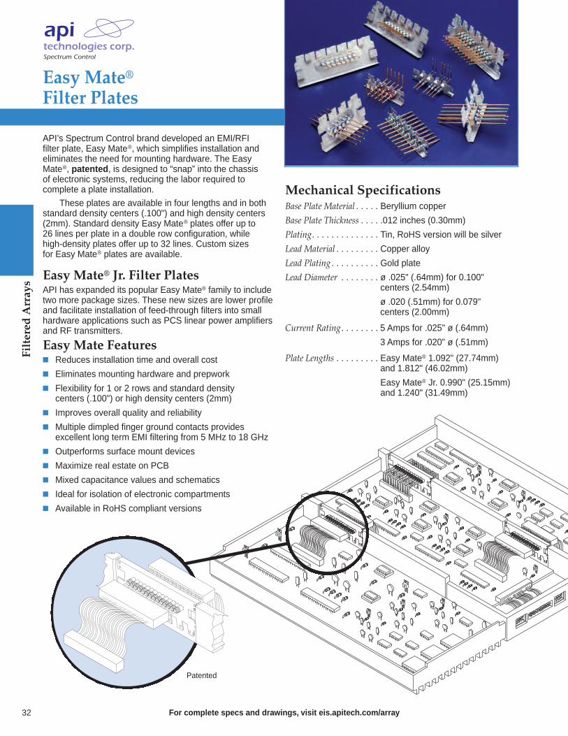
API’s Spectrum Control brand developed an EMI/RFI filter plate, Easy Mate®, which simplifies installation andeliminates the need for mounting hardware. The EasyMate®, patented, is designed to “snap” into the chassis of electronic systems, reducing the labor required to complete a plate installation.
These plates are available in four lengths and in bothstandard density centers (.100") and high density centers(2mm). Standard density Easy Mate® plates offer up to 26 lines per plate in a double row configuration, while high-density plates offer up to 32 lines. Custom sizes for Easy Mate® plates are available.
Easy Mate® Jr. Filter PlatesAPI has expanded its popular Easy Mate® family to includetwo more package sizes. These new sizes are lower profileand facilitate installation of feed-through filters into smallhardware applications such as PCS linear power amplifiersand RF transmitters.
Easy Mate Features Reduces installation time and overall cost
Eliminates mounting hardware and prepwork
Flexibility for 1 or 2 rows and standard densitycenters (.100") or high density centers (2mm)
Improves overall quality and reliability
Multiple dimpled finger ground contacts provides excellent long term EMI filtering from 5 MHz to 18 GHz
Outperforms surface mount devices
Maximize real estate on PCB
Mixed capacitance values and schematics
Ideal for isolation of electronic compartments
Available in RoHS compliant versions
Mechanical SpecificationsBase Plate Material . . . . . Beryllium copper
Base Plate Thickness . . . . .012 inches (0.30mm)
Plating. . . . . . . . . . . . . . Tin, RoHS version will be silver
Lead Material . . . . . . . . . Copper alloy
Lead Plating . . . . . . . . . . Gold plate
Lead Diameter . . . . . . . . ø .025" (.64mm) for 0.100" . . . . . . . . . . . . . . . . . . . centers (2.54mm)
. . . . . . . . . . . . . . . . . . . ø .020 (.51mm) for 0.079" centers (2.00mm)
Current Rating. . . . . . . . 5 Amps for .025" ø (.64mm)
. . . . . . . . . . . . . . . . . . . 3 Amps for .020" ø (.51mm)
Plate Lengths . . . . . . . . . Easy Mate® 1.092" (27.74mm) . . . . . . . . . . . . . . . . . . . and 1.812" (46.02mm)
. . . . . . . . . . . . . . . . . . . Easy Mate® Jr. 0.990" (25.15mm)
. . . . . . . . . . . . . . . . . . . and 1.240" (31.49mm)
Patented
32
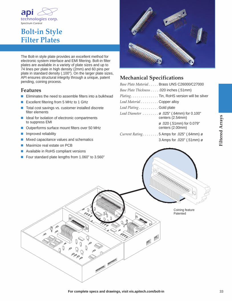
Mechanical SpecificationsBase Plate Material . . . . . Brass UNS C26000/C27000
Base Plate Thickness . . . . .020 inches (.51mm)
Plating. . . . . . . . . . . . . . Tin, RoHS version will be silver
Lead Material . . . . . . . . . Copper alloy
Lead Plating . . . . . . . . . . Gold plate
Lead Diameter . . . . . . . . ø .025" (.64mm) for 0.100" . . . . . . . . . . . . . . . . . . . centers (2.54mm)
. . . . . . . . . . . . . . . . . . . ø .020 (.51mm) for 0.079" centers (2.00mm)
Current Rating. . . . . . . . 5 Amps for .025" (.64mm) ø
. . . . . . . . . . . . . . . . . . . 3 Amps for .020" (.51mm) ø
Bolt-in Style Filter Plates
For complete specs and drawings, visit eis.apitech.com/bolt-in
The Bolt-in style plate provides an excellent method forelectronic system interface and EMI filtering. Bolt-in filterplates are available in a variety of plate sizes and up to 74 lines per plate in high density (2mm) and 60 pins per plate in standard density (.100"). On the larger plate sizes, API ensures structural integrity through a unique, patentpending, coining process.
Features Eliminates the need to assemble filters into a bulkhead
Excellent filtering from 5 MHz to 1 GHz
Total cost savings vs. customer installed discretefilter elements
Ideal for isolation of electronic compartmentsto suppress EMI
Outperforms surface mount filters over 50 MHz
Improved reliability
Mixed capacitance values and schematics
Maximize real estate on PCB
Available in RoHS compliant versions
Four standard plate lengths from 1.060" to 3.560"
33
Coining featurePatented
Filtered Arrays

Filtered Arrays
For complete specs and drawings, visit eis.apitech.com/latch34
Shrouded Latch Filter Plates
Shrouded Latch Filter Plates are an effective methodfor combining an electronic interface and EMI solutionin one package. The shrouded latch incorporates the bolt-in concept filter plate with the latching feature ofpopular ribbon cable headers. This product is availablein pin counts of 10 through 64 positions. The latch isavailable in a variety of standard heights.
The Shrouded Latch Filter Plate is ideal for securingand protecting the filter element from exposure to mechanical shock and vibration which could loosen the cable interface.
Features Available in 10 to 64 positions
Mates to most ribbon cable connectors
Variety of latch ejector heights available
Pins on .100" centers
Reliable cable retention for high vibration applications
Mixed capacitance values and schematics available
Excellent filtering from 5 MHz to 1 GHz and beyond
Shroud protects filter elements from potential damage
Available in RoHS compliant versions
Mechanical SpecificationsBase Plate Material . . . . . Brass UNS C26000/C27000
Base Plate Thickness . . . . .040" (1.0mm)
Plating. . . . . . . . . . . . . . Tin, RoHS version will be silver
Shrouded Material . . . . . Thermoplastic Polyester UL94V-0
Lead Material . . . . . . . . . Copper alloy
Lead Plating . . . . . . . . . . Gold plate
Lead Diameter . . . . . . . . ø .025" (0.6mm)
Current Rating. . . . . . . . 5 Amps

Mechanical SpecificationsCenter Spacing . . . . . . . . .438" (11.1 mm)
Wire Size . . . . . . . . . . . . AWG #12 max for 20A
Screw Size . . . . . . . . . . . 20A - #6-32, zinc-plated . . . . . . . . . . . . . . . . . . . philslot screws
Molded Material . . . . . . . Black, UL rated 94VO thermoplastic
Tightening Torque. . . . . . 9 in.-lbs. max.
Terminal . . . . . . . . . . . . Brass, tin-plated
Electrical SpecificationsOperating Temperature . . -55°C to 105°C
Working Voltage. . . . . . . 100VDC
Capacitance . . . . . . . . . . 2,500 pF to 5,200 pF
Dielectric Withstanding Voltage . . . 1700VDC
Current Rating. . . . . . . . 20A
D.C. Resistance . . . . . . . .01 ohms max.
Note: For product with AC rating, consult factory for 52-257-Series product and request data sheet. Product UL/CSA recognized.
Barrier Strip Filtered Terminal Blocks
For complete specs and drawings, visit eis.apitech.com/barrierblock
The barrier strip filtered terminal block is designed to provide excellent EMI/RFI filtering of AC and DC powerlines and control lines. This terminal block is available invarious sizes, with terminals for soldering or spade lugs. Application examples include filtering power supplies in telecommunications equipment, metering, industrial controls, instrumentation and EDP equipment.
Features UL recognized and CSA approved for DC voltages
E133076, UL 1059
LR92537, CSA STD 22.2 N°158-1987 and ECN584B
Filter element provides high insertion loss for EMI/RFI filtering of AC and DC power and control lines
Rugged construction provides protection to filteringelement; especially useful for repeated changes inwiring or field connections
2 to 6 terminals available (combine if larger number of terminals needed)
Cost-effective solution for industrial interconnectionEMI filtering problems
Termination options available: straight lead, male or female disconnects, pigtail (12 AWG = 0.081" (2.05mm); 22 AWG = 0.025" (0.64mm)
Available in RoHS compliant versions
35
Circuit SchematicPi Filter
Frequency Insertion Loss (dB)30 MHz 22
50 MHz 32
100 MHz 48
300 MHz 70
500 MHz 75
1000 MHz 75
Typical Loss (dB) In 50 Ohm Circuit
Filtered Arrays

36
Custom Filtered Arrays
For complete specs and drawings, visit eis.apitech.com/customarray
API Technologies’ Spectrum Control brand will custom design a filter plate or terminal block that meets your size,material and filtering requirements. We have engineered a variety of capacitive only filter elements that provide excellent RF isolation from 5 MHz to 1 GHz and beyond. In addition, we are capable of providing stringent testingand analysis of our filter plate or terminal block assemblies to MIL-F-15733 and MIL-F-28861.
In addition to our standard and custom filter plates and terminal blocks, we offer a number of value-added features designed to complement your manufacturing operation. Our marketing and engineering staff will evaluate your design or manufacturing parameters and develop a filter solution which provides increased filteringperformance economically.
API Capabilities Custom assemblies with varying cable lengths and terminations
Integrate a filter solution with other componentsto ensure a completely functional device
Perform EMC evaluations on your equipment,recommending proper placement of EMI/RFIfiltering components
Custom high reliability assemblies
Easy Mate®Patent pending
Bolt-inCoining processpatented
Lead stabilizerposition can beadjustable
Filtered HeadersReplace the unfiltered connector on your PC board withAPI’s low cost filtered header. This innovative new productallows you to meet EMC emissions and susceptibilitystandards with minimal or no board change.
Flat Conductor CablesFlat conductor cables are often selected as an effectivemethod of interconnection. API can save you time andmoney by installing conductor cables to your filter plates. Flat conductor cables are available in varying lengths,conductor counts and in several termination configurations.
Lead StabilizerAPI Technologies’ Spectrum Control brand has developed a filter plate lead stabilizer bar to protect leads during installation and ensure proper alignment to PCB.
Filtered Arrays

from performance to boardspace, to cost, we offer manyreasons and options for managing EMI @ the signal & power I/O
Low ground impedance – Full groundplate and metallic shell provide minimalimpedance and superior performancecompared to on-board filter with high impedance
Eliminate re-radiation – Filtered connector at interface leaves no path for bypassing the filter
Ground plane shielding – API’s filteredconnector ground planes shield the boxeven at the connector port
Efficient space utilization – Filters located in the connectors provide additional space on PCB board
Consistent performance – Filtered connectors provide more consistent pin to pin performance
Fewer components – Filtered connectors reduce component count creating cost savings
Reliability – API tests 100% of filters, on-board filters are usually spot tested
Advantages of a Filtered Connector
EMI Filtered Connectors
Series 700 High PerformanceConnectors feature feed-through capacitive and Pi filters for the most effective filtering… 42
Series 600 Hi-Density FilteredConnectors meet the growing need for increased circuit densities in smaller packages… 41
Series 500 Low-Profile Feed-ThroughConnectors deliver reliable EMI filtering in 90° PCB and straight PCB connectors… 40
Filtered Combo D-Sub Connectors use tubular capacitorsfor high insertion loss in signal,power and coaxial contacts… 43
Rugged USB Connectors feature a heavy-duty design able to connectto USB 2.0 or 1.1 ports… 45
Micro D Series Connectors allow designers to incorporate EMI filtering into even smaller packages… 44
Series F Ferrite Filtered Connectorsoffer a low cost, space saving solutionfor high frequency interference… 39
For complete specs and drawings, visit eis.apitech.com/dsub 37

EMI Filtered Connectors
38 For complete specs and drawings, visit eis.apitech.com/dsub
D-Sub ConnectorPart Numbering System
This part number represents a Series 500 connector with 15 contacts in a socket to straight PCB mount configuration. All connector positions have a capacitance value of 840 pF and there are 4-40 threads on mounting flange.Example: 56-513-012-TI
CapacitanceValueSeries 40001 = Always
Series 50010 = 120 pF11 = 440 pF12 = 840 pF13 = 1000 pF14 = 1500 pF
Series 60015 = 85 pF FT16 = 180 pF FT18 = 1000 pF FT19 = 4000 pF FT20 = Insulated
contact
Series 700See filter specifi-cation chart online.
Shell SizeSeries 400,Series 5000 = 9 Contacts1 = 15 Contacts2 = 25 Contacts3 = 37 Contacts
Series 600Hi-Density0 = 15 Contacts1 = 26 Contacts2 = 44 Contacts3 = 62 Contacts4 = 78 Contacts
Series 7000 = 9 Contacts1 = 15 Contacts2 = 25 Contacts3 = 37 Contacts4 = 50 Contacts
LineFiltering0 = All
positionssame
9 = Specialloading(Series600 only)
FilteredD-SubminiatureConnectors
OptionsSeries F
HD = Hi-Density(15 socket only)
Series 500TI = 4-40 threads on mounting
flange (.125" hole if notselected)
GBL = Grounded board lockincludes 4-40 threads(available only on 90° PCB)
GBLF = Grounded board lockand ferrite slabprovides enhanced LCperformance. (Availableonly on 90° PCB)
Series 600 Hi-DensityLI = 4-40 UNC insertsS = Solder dipped tails
50G = 50 µ (1.27 µm) goldGBL = Ground board lock
Series 700LI = 4-40 UNC inserts
LIM = Metric M3.0 self-locking threadsGB = Metal bracket provides ground
connection, includes 4-40 self-locking threads (for right angle mount only)
GBL = Grounded board lock(right angle)
GBL6 = For .062" boards (straightPCB mount) (1.57mm)
GBL9 = For .093" boards (straightPCB mount (2.36mm)
50G = 50 µ (1.27 µm) gold platingS = Solder dipped tailsJS = Jack screw mounting
For option combinations, consult factory.
ProductSeries4 = Series F
Ferrite
5 = Series 500Low Profile
6 = Series 600Hi-Density
7 = Series 700HighPerformance
Contact Type/Termination1 = Pin to solder cup2 = Pin to 90° PCB mount3 = Socket to straight PCB mount4 = Socket to 90° PCB mount5 = Pin-socket adapter6 = Socket to solder cup7 = Pin to straight PCB mount
Styles available for:Series 400 only 2, 3, 4, 7Series 500 only 2, 3, 4 & 7Series 600 only 1, 2, 3, 4, 5Series 700 1 thru 7
Note: 1 can be Pin to solder cupor Pin to PCB for Series 700.
- Standard connectorF - RoHS compliant version
56 - 5 1 3 - 0 12 - TI
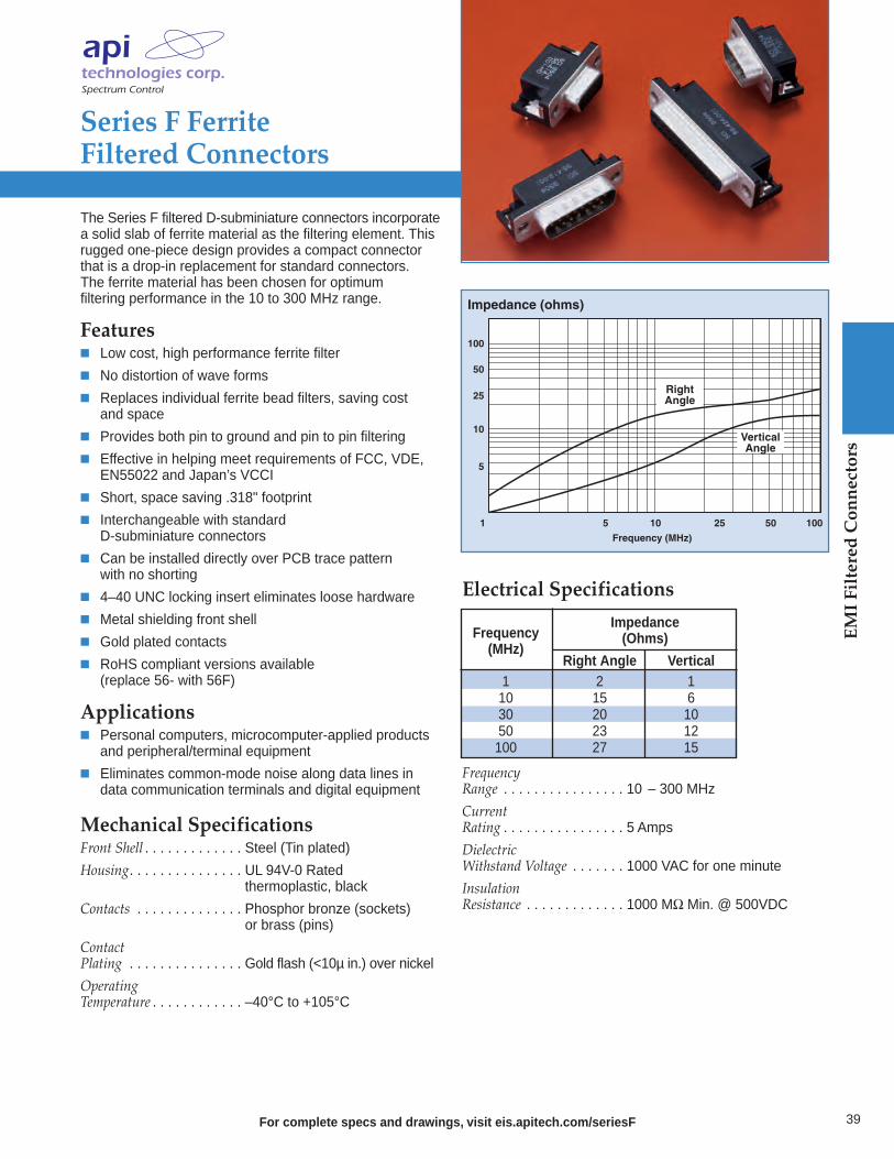
For complete specs and drawings, visit eis.apitech.com/seriesF
Series F Ferrite Filtered Connectors
The Series F filtered D-subminiature connectors incorporatea solid slab of ferrite material as the filtering element. Thisrugged one-piece design provides a compact connectorthat is a drop-in replacement for standard connectors. The ferrite material has been chosen for optimum filtering performance in the 10 to 300 MHz range.
Features Low cost, high performance ferrite filter
No distortion of wave forms
Replaces individual ferrite bead filters, saving cost and space
Provides both pin to ground and pin to pin filtering
Effective in helping meet requirements of FCC, VDE, EN55022 and Japan’s VCCI
Short, space saving .318" footprint
Interchangeable with standard D-subminiature connectors
Can be installed directly over PCB trace pattern with no shorting
4–40 UNC locking insert eliminates loose hardware
Metal shielding front shell
Gold plated contacts
RoHS compliant versions available (replace 56- with 56F)
Applications Personal computers, microcomputer-applied products and peripheral/terminal equipment
Eliminates common-mode noise along data lines in data communication terminals and digital equipment
Electrical Specifications
Frequency Range . . . . . . . . . . . . . . . . 10 – 300 MHz
CurrentRating . . . . . . . . . . . . . . . . 5 Amps
DielectricWithstand Voltage . . . . . . . 1000 VAC for one minute
InsulationResistance . . . . . . . . . . . . . 1000 MΩ Min. @ 500VDC
1
Frequency (MHz)
Impedance (ohms)
5 25 1005010
5
10
100
25
50
VerticalAngle
RightAngle
Impedance Frequency (Ohms)(MHz)
Right Angle Vertical1 2 110 15 630 20 1050 23 12100 27 15
Mechanical SpecificationsFront Shell . . . . . . . . . . . . . Steel (Tin plated)
Housing. . . . . . . . . . . . . . . UL 94V-0 Rated . . . . . . . . . . . . . . . . . . . . . thermoplastic, black
Contacts . . . . . . . . . . . . . . Phosphor bronze (sockets) . . . . . . . . . . . . . . . . . . . . . or brass (pins)
Contact Plating . . . . . . . . . . . . . . . Gold flash (<10µ in.) over nickel
OperatingTemperature . . . . . . . . . . . . –40°C to +105°C
39
EMI Filtered Connectors

EMI Filtered Connectors
40 For complete specs and drawings, visit eis.apitech.com/series500
Series 500 Low ProfileFiltered Connectors
API’s Spectrum Control brand of Series 500 are cost effective, highly reliable EMI filtered D-subminiature connectors that feature a .318" footprint for 90 degree PCB connectors and a low profile housing on straight PCB connectors. Series 500 filtered D-subs are “drop-in”replacements for standard unfiltered D-sub connectors anduse tubular capacitors for high performance EMI filtering.
Series 500 capacitive filtered D-sub connectors arean ideal solution to FCC/EC/VCCI emissions problems.These connectors are designed to protect equipmentfrom external EMI noise and eliminate system glitches.
Features “Drop-in” replacements for unfiltered D-subminiatures
Compact design, featuring .318" footprint
Tubular feed-through capacitors provide filtering superior to on-board components
Ground plane design provides EMI shielding
Full interchangeability; based on MIL-C-24308
Each connector position is tested 100% for critical electrical parameters to ensure consistent performance
Insulators are UL recognized UL94-V0 flammability rated
9, 15 and 25 shell sizes
Available with board lock feature and 4-40 mounting threads
Selective filtering available
UL/CSA approved
Greater than 40 dB filtering up through 1 GHz without resonances
Bi-directional control of EMI at the I/O ports
Mechanical SpecificationsShell . . . . . . . . . . . . . . . . . Steel, tin plated
Insulators . . . . . . . . . . . . . Glass-filled polyester,. . . . . . . . . . . . . . . . . . . . . flammability UL94V-O
Pin Contacts . . . . . . . . . . . Copper alloy CA725, 15 microinch. . . . . . . . . . . . . . . . . . . . . (0.38 µm) gold plated* over nickel
Socket Contacts . . . . . . . . . Copper alloy CA725, . . . . . . . . . . . . . . . . . . . . . 30 microinch (0.76 µm). . . . . . . . . . . . . . . . . . . . . gold plated* over nickel
*Heavier gold plating available upon request.Ground Plane. . . . . . . . . . . Phosphor bronze, nickel plated
OperatingTemperature . . . . . . . . . . . . -40°C to +125°C
Capacitors . . . . . . . . . . . . . Proprietary barium titanate. . . . . . . . . . . . . . . . . . . . . ceramic formulations
1MHz 10MHz 100MHz 1GHzFrequency
60
50
40
30
20
10
0
Inse
rtio
n Lo
ss (d
B)
120
pF
1500
pF
440 pF
1000 pF
5GHz
840 pF is typically within 2 dB of 1000 pF curve.
Typical Insertion Loss
Electrical SpecificationsCurrent Rating. . . . . . . . . . 5 Amps
RF Current Rating . . . . . . . 0.3 Amps
Contact Resistance . . . . . . . 10 mΩ maximum
Capacitance . . . . . . . . . . . . 120, 440, 840, 1000, 1500 pF ±30%
Working Voltage. . . . . . . . . 100 VDC
Dielectric Withstanding Voltage . . . . . . 300 VDC
Insulation Resistance . . . . . 1 GΩ minimum
UL Recognized . . . . . . . . . . Under category of communication. . . . . . . . . . . . . . . . . . . . . circuit accessories, File #E149046
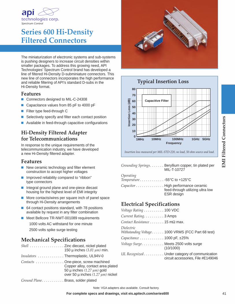
For complete specs and drawings, visit eis.apitech.com/series600
Series 600 Hi-DensityFiltered Connectors
The miniaturization of electronic systems and sub-systemsis pushing designers to increase circuit densities withinsmaller packages. To address this growing need, API Technologies’ Spectrum Control brand has developed aline of filtered Hi-Density D-subminiature connectors. Thisnew line of connectors incorporates the high performanceand reliable filtering of API’s standard D-subs in the Hi-Density format.
Features Connectors designed to MIL-C-24308
Capacitance values from 85 pF to 4000 pF
Filter type feed-through C
Selectively specify and filter each contact position
Available in feed-through capacitive configurations
0
80
60
20
40
10
30
50
70
Inse
rtio
n L
oss
(d
B)
Frequency1MHz 10MHz 100MHz 1GHz 5GHz
Capacitive Filter
Typical Insertion Loss
Insertion loss measured per MIL-STD-220, no load, 50 ohm source and load.
Note: VGA adapters also available. Consult factory.
Mechanical SpecificationsShell . . . . . . . . . . . . . . . . . Zinc diecast, nickel plated. . . . . . . . . . . . . . . . . . . . . 150 µ inches (3.81 µm) min.
Insulators . . . . . . . . . . . . . Thermoplastic, UL94V-0
Contacts . . . . . . . . . . . . . . One-piece, screw machined. . . . . . . . . . . . . . . . . . . . . Copper alloy, contact area plated. . . . . . . . . . . . . . . . . . . . . 50 µ inches (1.27 µm) gold. . . . . . . . . . . . . . . . . . . . . over 50 µ inches (1.27 µm) nickel
Ground Plane. . . . . . . . . . . Brass, solder plated
Hi-Density Filtered Adapterfor TelecommunicationsIn response to the unique requirements of the telecommunication industry, we have developed a new Hi-Density filtered adapter.
Features New ceramic technology and filter element construction to accept higher voltages
Improved reliability compared to “ribbon”type connectors
Integral ground plane and one-piece diecast housing for the highest level of EMI integrity
More contacts/wires per square inch of panel space through Hi-Density arrangements
64 contact positions standard, with 78 positions available by request in any filter combination
Meet Bellcore TR-NWT-001089 requirements 1000 volts AC withstand for one minute 2500 volts spike surge testing
Grounding Springs. . . . . . . Beryllium copper, tin plated per. . . . . . . . . . . . . . . . . . . . . MIL-T-10727
OperatingTemperature . . . . . . . . . . . . -55°C to +125°C
Capacitor . . . . . . . . . . . . . . High performance ceramic. . . . . . . . . . . . . . . . . . . . . feed-through utilizing ultra low. . . . . . . . . . . . . . . . . . . . . ESR design
Electrical SpecificationsVoltage Rating . . . . . . . . . . 100 VDC
Current Rating. . . . . . . . . . 3 Amps
Contact Resistance . . . . . . . 15 mΩ max.
DielectricWithstanding Voltage . . . . . . 1000 VRMS (FCC Part 68 test)
Capacitance . . . . . . . . . . . . 1000 pF, ±25%
Voltage Surge . . . . . . . . . . . Meets 2500 volts surge . . . . . . . . . . . . . . . . . . . . . (10/1000)
UL Recognized . . . . . . . . . . Under category of communication. . . . . . . . . . . . . . . . . . . . . circuit accessories, File #E149046
41
EMI Filtered Connectors
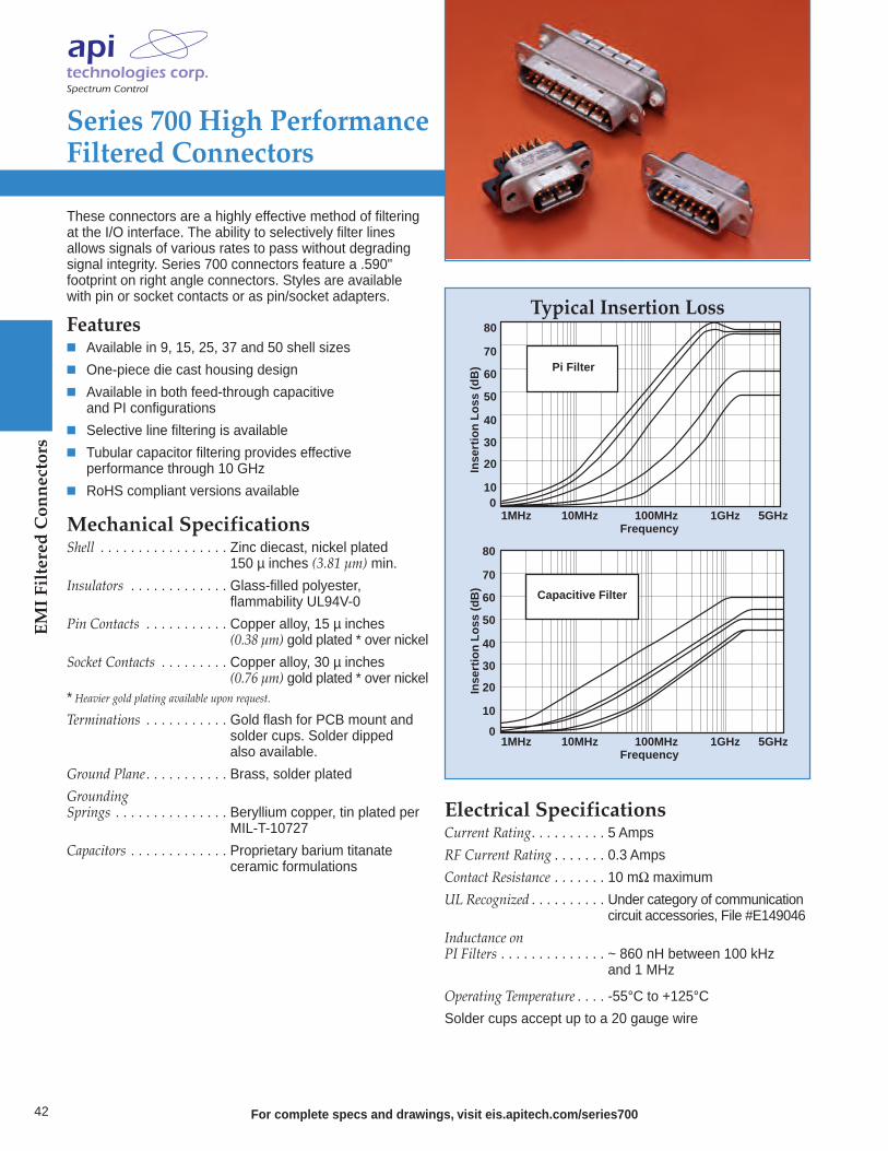
EMI Filtered Connectors
42 For complete specs and drawings, visit eis.apitech.com/series700
Series 700 High PerformanceFiltered Connectors
80
60
20
40
0
Frequency1MHz 10MHz 100MHz 1GHz
10
30
50
70
80
60
20
40
0
10
30
50
70
Inse
rtio
n L
oss
(d
B)
Inse
rtio
n L
oss
(d
B)
Pi Filter
Capacitive Filter
5GHz
Frequency1MHz 10MHz 100MHz 1GHz 5GHz
Typical Insertion Loss
Mechanical SpecificationsShell . . . . . . . . . . . . . . . . . Zinc diecast, nickel plated. . . . . . . . . . . . . . . . . . . . . 150 µ inches (3.81 µm) min.
Insulators . . . . . . . . . . . . . Glass-filled polyester,. . . . . . . . . . . . . . . . . . . . . flammability UL94V-0
Pin Contacts . . . . . . . . . . . Copper alloy, 15 µ inches. . . . . . . . . . . . . . . . . . . . . (0.38 µm) gold plated * over nickel
Socket Contacts . . . . . . . . . Copper alloy, 30 µ inches. . . . . . . . . . . . . . . . . . . . . (0.76 µm) gold plated * over nickel* Heavier gold plating available upon request.
Terminations . . . . . . . . . . . Gold flash for PCB mount and . . . . . . . . . . . . . . . . . . . . . solder cups. Solder dipped . . . . . . . . . . . . . . . . . . . . . also available.
Ground Plane. . . . . . . . . . . Brass, solder plated
GroundingSprings . . . . . . . . . . . . . . . Beryllium copper, tin plated per. . . . . . . . . . . . . . . . . . . . . MIL-T-10727
Capacitors . . . . . . . . . . . . . Proprietary barium titanate. . . . . . . . . . . . . . . . . . . . . ceramic formulations
These connectors are a highly effective method of filteringat the I/O interface. The ability to selectively filter lines allows signals of various rates to pass without degradingsignal integrity. Series 700 connectors feature a .590" footprint on right angle connectors. Styles are availablewith pin or socket contacts or as pin/socket adapters.
Features Available in 9, 15, 25, 37 and 50 shell sizes
One-piece die cast housing design
Available in both feed-through capacitive and PI configurations
Selective line filtering is available
Tubular capacitor filtering provides effective performance through 10 GHz
RoHS compliant versions available
Electrical SpecificationsCurrent Rating. . . . . . . . . . 5 Amps
RF Current Rating . . . . . . . 0.3 Amps
Contact Resistance . . . . . . . 10 mΩ maximum
UL Recognized . . . . . . . . . . Under category of communication. . . . . . . . . . . . . . . . . . . . . circuit accessories, File #E149046
Inductance onPI Filters . . . . . . . . . . . . . . ~ 860 nH between 100 kHz . . . . . . . . . . . . . . . . . . . . . and 1 MHz
Operating Temperature . . . . -55°C to +125°C
Solder cups accept up to a 20 gauge wire
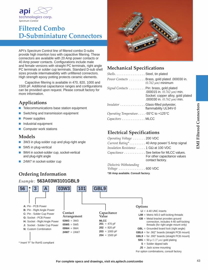
Filtered Combo D-Subminiature Connectors
For complete specs and drawings, visit eis.apitech.com/combo
API’s Spectrum Control line of filtered combo D-subs provide high insertion loss with capacitive filtering. Theseconnectors are available with 20 Amp power contacts or 40 Amp power contacts. Configurations include male and female versions with straight PC terminals, right anglePC terminals or solder cup terminals. Standard D-sub shellsizes provide intermateability with unfiltered connectors.High strength epoxy potting protects ceramic elements.
Capacitive filtering is available in 470, 820, 1000 and1500 pF. Additional capacitance ranges and configurationscan be provided upon request. Please consult factory formore information.
Applications Telecommunications base station equipment
Switching and transmission equipment
Power supplies
Industrial equipment
Computer work stations
Models 3W3 in plug-solder cup and plug-right angle
5W5 in plug-vertical
9W4 in socket-solder cup, socket-vertical and plug-right angle
24W7 in socket-solder cup
Electrical SpecificationsOperating Voltage . . . . . . . 200 VDCCurrent Rating* . . . . . . . . . 40 Amp power/ 5 Amp signalInsulation Resistance . . . . . 1 GΩ at 100 VDCCapacitance . . . . . . . . . . . . See below for MLCC values. . . . . . . . . . . . . . . . . . . . . . . For other capacitance values . . . . . . . . . . . . . . . . . . . . . . contact factory.Dielectric WithstandingVoltage . . . . . . . . . . . . . . . 600 VDC*30 Amp available. Consult factory.
Mechanical SpecificationsShells. . . . . . . . . . . . . . . . . Steel, tin plated
Power Contacts . . . . . . . . . Brass, gold plated .000030 in. . . . . . . . . . . . . . . . . . . . . . (0.762 µm) minimum
Signal Contacts . . . . . . . . . Pin: brass, gold plated. . . . . . . . . . . . . . . . . . . . . .000015 in. (0.762 µm) min.. . . . . . . . . . . . . . . . . . . . . Socket: copper alloy, gold plated
.000030 in. (0.762 µm) min.
Insulator . . . . . . . . . . . . . . Glass-filled polyester,. . . . . . . . . . . . . . . . . . . . . flammability UL94V-0
Operating Temperature . . . . -55°C to +125°C
Capacitors . . . . . . . . . . . . . MLCC
Ordering InformationExample: 563A03W3101GBL9
A: Pin - PCB PowerB: Pin - Right Angle PowerC: Pin - Solder Cup PowerG: Socket - PCB PowerH: Socket - Right Angle PowerJ: Socket - Solder Cup PowerN: Custom Combination
OptionsLI = 4-40 UNC inserts
LIM = Metric M3.0 self-locking threadsGB = Metal bracket provides ground
connection, includes 4-40 self-locking threads (for right angle mount only)
GBL = Grounded board lock (right angle)GBL6 = for .062" boards (straight PCB mount)GBL9 = for .093" boards (straight PCB mount)50G = 50 µ (1.27 µm) gold platingS = Solder dipped tailsJS = Jack screw mounting
For option combinations, consult factory.
CapacitanceValueMLCC201 = 470 pF202 = 820 pF203 = 1000 pF204 = 1500 pF
ContactArrangement03W3 = 3W305W5 = 5W509W4 = 9W424W7 = 24W7
* Insert “F” for RoHS compliant
56 * 3 A 03W3 101 GBL9
43
EMI Filtered Connectors

EMI Filtered Connectors
44
Ordering InformationExample: 56-F011-110-JP
FilteredConnectors
RoHS Compliant
Shell Size/Number ofContacts
0 - 9 contacts1 - 15 contacts2 - 21 contacts3 - 25 contacts4 - 31 contacts5 - 37 contacts
Contact Type/Termination
1 - Pin to solder cup 2 - Pin to right angle
(Standard profile)*3 - Socket to PC tail*4 - Socket to right angle
(Standard profile)*6 - Socket to solder cup 7 - Pin to PC tail*
Line Filtering
1 - All positions same 2 - Select load
OptionsSC - Solder cupJP - #2-56 jack postJS - #2-56 jack screwPC - PC tail and right angleTI - Threaded insertJT - Jack post and
threaded insert
CapacitanceValue/Type
High Performance01 - 100 pF FT 02 - 470 pF FT03 - 820 pF FT04 - 1500 pF FT05 - 4700 pF FT
Standard Performance10 - 100 pF COB 11 - 470 pF COB12 - 820 pF COB13 - 1500 pF COB14 - 4700 pF COB
All capacitance values ±20% @ 25°C
56 F 0 1 1 - 1 10 - JP
Filtered Micro D Series Connectors
For designs that require even smaller connector packages, API’s Spectrum Control brand has designed a line of filtered Micro D-Subminiature connectors. This line of connectors offers a range of reliable filteringoptions, including capacitive and ESD versions, and several sizes and termination options. API has a Micro D-sub connector to satisfy your smallest space constraints.
Features Light weight
Compact size
Environmentally sealed contact area when mated
Corrosion resistant
Durable (500 cycles min.)
Superior electrical performance
RoHS compliant
Mechanical SpecificationsShell . . . . . . . . . . . . . . . Aluminum, electroless nickel . . . . . . . . . . . . . . . . . . . plated 500 µ in (12.7 µm) minimum
Insulator . . . . . . . . . . . . Glass filled polyester, . . . . . . . . . . . . . . . . . . . flammability UL94V-0
Contacts. . . . . . . . . . . . . Copper alloy, gold plated 50 µ in . . . . . . . . . . . . . . . . . . . (1.27 µm) minimum
Potting . . . . . . . . . . . . . Flammability UL94V-0
Interfacial Seal . . . . . . . . Silicon
Electrical SpecificationsOperating Voltage. . . . . . 100 VDC
Dielectric Withstanding Voltage . . . 300 VDC
Current Rating. . . . . . . . 3 Amps
Insulation Resistance . . . 5G ohms @ 100 VDC
For complete specs and drawings, visit eis.apitech.com/micro
Micro D
This part number represents a micro D-sub connector with a shell size of 15 anda pin to solder cup configuration. All lines are filtered with same capacitancevalue, which is 100 pF COB. The connector includes an optional #2-56 jack post.
* Right angle and PC tail length (Standard Profile) is 0.109. Other lengths available, consult factory.
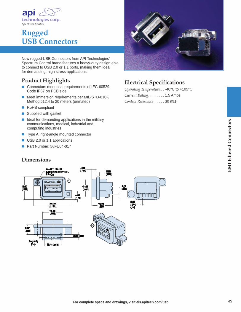
For complete specs and drawings, visit eis.apitech.com/usb
RuggedUSB Connectors
New rugged USB Connectors from API Technologies’Spectrum Control brand features a heavy-duty design able to connect to USB 2.0 or 1.1 ports, making them ideal for demanding, high stress applications.
Product Highlights Connectors meet seal requirements of IEC-60529, Code IP67 on PCB side
Meet immersion requirements per MIL-STD-810F, Method 512.4 to 20 meters (unmated)
RoHS compliant
Supplied with gasket
Ideal for demanding applications in the military, communications, medical, industrial and computing industries
Type A, right-angle mounted connector
USB 2.0 or 1.1 applications
Part Number: 56FU04-017
Dimensions
Electrical SpecificationsOperating Temperature . . -40°C to +105°C
Current Rating. . . . . . . . 1.5 Amps
Contact Resistance . . . . . 30 mΩ
45
EMI Filtered Connectors

flexible, conformable andlightweight Quietshield™
products deliver effective EMI shielding across seams or gaps within an enclosure
Quietshield™ Gaskets & Shielding
Shielding Tapes and Fabrics are flexible,lightweight, and easy-to-install shielding materials offering high conductivity with a low electrical resistance and are available in a variety of fabric styles.
Wire Mesh Gaskets are available as all mesh or elastomer core mesh gaskets. They provide excellent heat and corrosion resistance and are used between two surfaces to maintain electrical continuity while shielding electromagnetic waves.
Conductive Silicone is used for its heatresistant properties and can be producedin many different forms such as sheets,molded parts, die-cuts or strips. Theseconductive elastomers are water resistant,can eliminate static electricity, and act as an absorber at high frequencies.
Foam Over Fabric are low cost, soft andeasy to apply. These gaskets are available in a variety of materials and profiles, including rectangular, “D” shaped, FL shaped and DD shaped.
Waved Metal Gaskets, Fabric OverFoam Gaskets and I/O ConnectorElectromagnetic Shielding Gasketsare flat products used to provide a ground contact between a metalconnector and the electronic enclosure or mating connector.
46
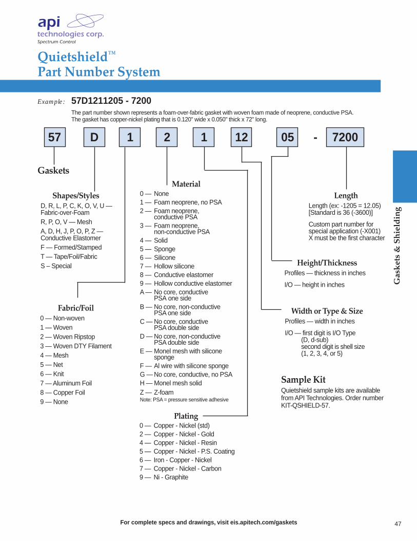
Quietshield™Part Number System
For complete specs and drawings, visit eis.apitech.com/gaskets
Gaskets & Shielding
Gaskets
LengthLength (ex: -1205 = 12.05)[Standard is 36 (-3600)]
Custom part number for special application (-X001) X must be the first character
57 D 1 2 1 12 05 - 7200
Sample KitQuietshield sample kits are available from API Technologies. Order number KIT-QSHIELD-57.
Shapes/StylesD, R, L, P, C, K, O, V, U — Fabric-over-FoamR, P, O, V — MeshA, D, H, J, P, O, P, Z — Conductive ElastomerF — Formed/StampedT — Tape/Foil/FabricS – Special
Fabric/Foil0 — Non-woven1 — Woven2 — Woven Ripstop3 — Woven DTY Filament4 — Mesh5 — Net6 — Knit7 — Aluminum Foil8 — Copper Foil9 — None
Plating0 — Copper - Nickel (std)2 — Copper - Nickel - Gold4 — Copper - Nickel - Resin5 — Copper - Nickel - P.S. Coating6 — Iron - Copper - Nickel7 — Copper - Nickel - Carbon9 — Ni - Graphite
Width or Type & SizeProfiles — width in inches
I/O — first digit is I/O Type (D, d-sub)second digit is shell size (1, 2, 3, 4, or 5)
Height/ThicknessProfiles — thickness in inches
I/O — height in inches
Material0 — None1 — Foam neoprene, no PSA2 — Foam neoprene,
conductive PSA3 — Foam neoprene,
non-conductive PSA4 — Solid5 — Sponge6 — Silicone7 — Hollow silicone8 — Conductive elastomer9 — Hollow conductive elastomerA — No core, conductive
PSA one sideB — No core, non-conductive
PSA one sideC — No core, conductive
PSA double sideD — No core, non-conductive
PSA double sideE — Monel mesh with silicone
spongeF — Al wire with silicone spongeG —No core, conductive, no PSAH — Monel mesh solidZ — Z-foamNote: PSA = pressure sensitive adhesive
Example: 57D1211205 - 7200The part number shown represents a foam-over-fabric gasket with woven foam made of neoprene, conductive PSA. The gasket has copper-nickel plating that is 0.120" wide x 0.050" thick x 72" long.
47
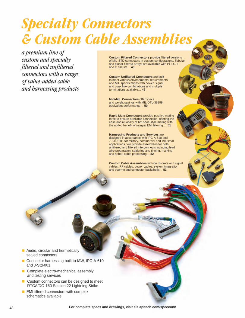
48
a premium line of custom and specialty filtered and unfiltered connectors with a range of value-added cable and harnessing products
Audio, circular and hermetically sealed connectors
Connector harnessing built to IAW, IPC-A-610and J-Std-001
Complete electro-mechanical assembly and testing services
Custom connectors can be designed to meetRTCA/DO-160 Section 22 Lightning Strike
EMI filtered connectors with complex schematics available
Specialty Connectors & Custom Cable Assemblies
Harnessing Products and Services are designed in accordance with IPC-A-610 and J-STD-001 for military, commercial and industrialapplications. We provide assemblies for both unfiltered and filtered interconnects including leadwire preparation, soldering and tinning, markingand ribbon cable processing… 52
Custom Filtered Connectors provide filtered versions of MIL-STD connectors in custom configurations. Tubular and planar filtered arrays are available with Pi, LC, T and C circuits… 49
Custom Unfiltered Connectors are built to meet various environmental requirements and MIL specifications with power, signal and coax line combinations and multiple terminations available… 49
For complete specs and drawings, visit eis.apitech.com/specconn
Mini-MIL Connectors offer space and weight savings with MIL-DTL-38999 equivalent performance… 50
Rapid Mate Connectors provide positive mating force to ensure a reliable connection, offering the ease and reliability of hot shoe style mating with the added benefit of integral EMI filtering.… 51
Custom Cable Assemblies include discrete and signalcables, RF cables, power cables, system integrationand overmolded connector backshells… 53

For complete specs and drawings, visit eis.apitech.com/circular
Specialty Connectors
Custom Filtered Connectors for MIL & Hi-Rel ApplicationsAPI Technologies’ Spectrum Control brand offers a complete line of compact and extended shell filtered connectors providing a wide range of design flexibility. Our compact shell filtered connectors offer designers an effective filtering device that reduces the amount of real estate required within a product enclosure. Our extendedshell connectors are constructed by adding either planar or tubular capacitor filtering to the rear of a standard connector, which makes them ideal when quick turnaround is required for prototype devices.
Styles offered include the following, as well as custom designs.
MIL-DTL-38999 MIL-DTL-55116
MIL-DTL-83723 MIL-DTL-24308
MIL-DTL-26482 MIL-DTL-5015
We offer tubular and planar style filtered arrays in Pi, LC, T and C circuits with TVS protection also available. Reliability is ensured through 100% testing of each position for critical electrical parameters.
Custom Unfiltered ConnectorsAPI also offers unfiltered custom connector design and manufacturing. Parts can be designed to meet yourmechanical and environmental specifications or those of similar QPL connectors.
Features Built to MIL specifications
Custom shells to fit your available space
Multiple terminations available
Built to meet various environmental requirements
Integral strain relief
Power, signal and coax line combinations
Vertically IntegratedAPI’s Spectrum Control line of custom filtered and unfiltered connector offerings are fully vertically integrated. Components including capacitors and shells are manufactured by API, providing our customers high quality parts at very competitive prices, with the industry’s shortest lead times.
Specialty Connectors
& Custom
Cable Assem
blies
Tubular Filtered Connector
Unfiltered Connectors
Planar Filtered Connector
49

Specialty Connectors
& Custom
Cable Assem
blies
50 For complete specs and drawings, visit eis.apitech.com/mini-mil
Mini-MILConnectors
API’s Spectrum Control line of new Mini-MIL circular connectors are small and lightweight offering space andweight savings while providing equivalent performance tostandard MIL-DTL-38999 connectors. These connectorsare available filtered with C, Pi or mixed capacitance, or unfiltered, and can be customized to satisfy various mechanical and electrical requirements. These connectorsare ideal for military, industrial and medical applicationswhere space restrictions do not allow for larger 38999 connectors.
SpecificationsEngagement Types: Bayonet
Single-start UN thread
Double-start ACME thread
Triple-start ACME thread
Termination Types: PC tail
Solder cup
Crimp removable
Piggyback socket
Custom
Receptacle Types: Flange mount (front or rear mount)
Jam nut (front or rear mount)
In-line
Minimum Insertion Loss (dB)
Cut-Off Freq. MHz
Working Voltage
AC 85°C
DC 85°C
1MHz
10MHz
100MHz
500MHz
1,000MHz
DielectricWithstandingVoltage (VDC)
Capacitance(pF, GMV)*
1,000
2,000
3,000
5,000
7,000 200
200
200
200
200 115 500
500
500
500
500
5
1
1
1
—
—
4
9
— 12
16
19
21
26
30
34
37
34
39
43
46
49
39
44
48
52
55
1
31
115
115
115
10,000
20,000 100
200 500
250
1 21
26
39
44
52
57
57
58
4
9.50
115
—
115
Electrical Characteristics with C Filter
Electrical Characteristics with Pi FilterMinimum Insertion Loss
(dB)
Cut-Off Freq. MHz
Working Voltage
AC 85°C
DC 85°C
1MHz
10MHz
100MHz
500MHz
1,000MHz
DielectricWithstandingVoltage (VDC)
Capacitance(pF, GMV)*
1,000
2,000
3,000
5,000
7,000 200
200
200
200
200 115 500
500
500
500
500
5
1
1
1
—
—
4
8
— 11
14
18
28
39
47
54
60
54
65
70
70
70
65
70
70
70
70
1
31
115
115
115
10,000
20,000 100
200 500
250
1 22
33
64
70
70
70
70
70
4
9.50
115
—
115
* Custom values available.
Mechanical SpecificationsShell . . . . . . . . . . . . . . . Eight shell sizes are available in . . . . . . . . . . . . . . . . . . . either pin or socket contact genders
Shell Materials . . . . . . . . Aluminum, stainless steel, . . . . . . . . . . . . . . . . . . . composite, custom
Contacts. . . . . . . . . . . . . Pin and socket contacts are . . . . . . . . . . . . . . . . . . . available in 1 to 55 contacts in . . . . . . . . . . . . . . . . . . . various combinations of size. . . . . . . . . . . . . . . . . . . 23 to size 12.

For complete specs and drawings, visit eis.apitech.com/rapidmate
Rapid Mate Connectors
51
API’s Spectrum Control brand Rapid Mate connectors offerthe ease and reliability of hot shoe style mating with theadded benefit of integral EMI filtering. By mating via springloaded, compliant contacts, Rapid Mate connectors providepositive mating force to ensure a reliable connection. Thismethod provides rapid connection with low mating force, allowing for some misalignment during mating.
Additionally, the EMI filter experts at API can design a filtered Rapid Mate connector built to your requirements,providing the advantages of hot shoe style mating while ensuring system functionality in EMI-prone applications.
Applications Military and commercial communications systems
Thermal and ambient light imaging cameras
Docking stations
Scanners
Minimum Insertion Loss - Decibels (dB)50 ohm system per MIL-STD-220 (no load)
5MHz
Capacitance
ToleranceValue 10MHz
20MHz
50MHz
100MHz
200MHz
500MHz
1GHz
WorkingVoltage DC-55°C to+125°C
Filter*Circuits
FilterDesignation
A
B
C
D
E
F
G
H
I
J
K
L
M
N
O
P
Q
R
S
T
Pi
5000 pF
2500 pF
1700 pF
1000 pF
820 pF
470 pF
135 pF
100 pF
68 pF
10 pF
4000 pF
2500 pF
1500 pF
1000 pF
820 pF
470 pF
135 pF
100 pF
68 pF ±20% 77 100V
100V
100V
100V
100V
100V
100V
100V
100V
100V
100V
100V
100V
100V
100V
100V
100V
50V
—
—
—
—
—
—
—
—
—
—
—
— 1
7
12
14
16
23
27
—
1
5
13
18
20
22
29
34
3
6
10
19
24
26
29
35
38
10
14
16
25
30
32
36
38
42
16
19
20
27
33
35
37
40
46
— 2
6
7
10
17
21
—
—
—
—
—
—
—
—
—
—
—
—
—
—
—
—
—
— —
1
5
9
2
3
4
11
15
1
4
9
6
9
15
2
4
14
16
28
7
—
—
1
9
13
28
28
41
16
1
2
6
18
23
35
41
53
24
6
9
17
22
31
49
54
66
36
17
22
26
36
45
64
70
70
51
23
28
34
43
52
69
70
70
59
100V
53
23
11
6
5
3.5
1.3
.8
635
65
46
25
11
6
5
1.9
1.3
.7
±20%
±20%
±20%
±20%
±20%
±20%
±20%
±20%
±20%
±20%
+100/-0%
+100/-0%
+100/-0%
+100/-0%
+100/-0%
+100/-0%
+100/-0%
Max.
C
Insulated
GroundedInsert
3 dB MaxCut-off
Frequency(MHz)
— —
—
—
—
—
—
—
—
—
—
—
—
—
EMI Filter PerformanceThe electrical characteristics table indicates the performance of feed-through capacitors and Pi type filters. Utilize this information to specify the EMI filteringcomponents included in your connector. Selective loadingand custom values can also be designed.
Features Custom filtering
100% tested before shipment
Rugged and reliable
Resists sand, dust and water
Low, flexible mating force
Specialty Connectors
& Custom
Cable Assem
blies
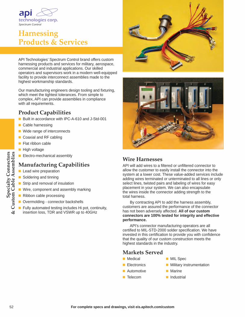
Harnessing Products & Services
API Technologies’ Spectrum Control brand offers custom harnessing products and services for military, aerospace,commercial and industrial applications. Our skilled operators and supervisors work in a modern well-equippedfacility to provide interconnect assemblies made to thehighest workmanship standards.
Our manufacturing engineers design tooling and fixturing,which meet the tightest tolerances. From simple to complex, API can provide assemblies in compliance with all requirements.
Product Capabilities Built in accordance with IPC-A-610 and J-Std-001
Cable harnessing
Wide range of interconnects
Coaxial and RF cabling
Flat ribbon cable
High voltage
Electro-mechanical assembly
Manufacturing Capabilities Lead wire preparation
Soldering and tinning
Strip and removal of insulation
Wire, component and assembly marking
Ribbon cable processing
Overmolding - connector backshells
Fully automated testing includes Hi pot, continuity, insertion loss, TDR and VSWR up to 40GHz
Wire HarnessesAPI will add wires to a filtered or unfiltered connector toallow the customer to easily install the connector into thesystem at a lower cost. These value-added services includeadding wires terminated or unterminated to all lines or onlyselect lines, twisted pairs and labeling of wires for easyplacement in your system. We can also encapsulate the wires inside the connector adding strength to the total harness.
By contracting API to add the harness assembly, customers are assured the performance of the connectorhas not been adversely affected. All of our custom connectors are 100% tested for integrity and effectiveperformance.
API’s connector manufacturing operators are all certified to MIL-STD-2000 solder specification. We have invested in this certification to provide you with confidencethat the quality of our custom construction meets the highest standards in the industry.
Markets Served Medical MIL Spec
Electronics Military instrumentation
Automotive Marine
Telecom Industrial
52 For complete specs and drawings, visit eis.apitech.com/custom
Specialty Connectors
& Custom
Cable Assem
blies
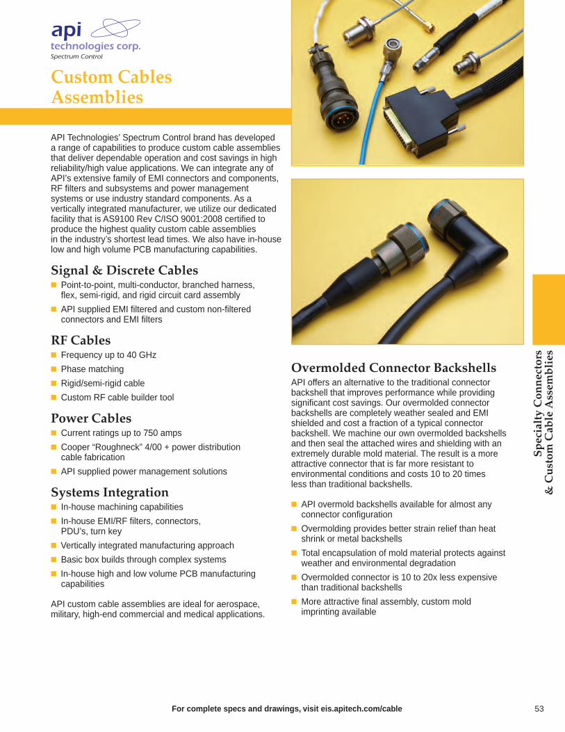
Specialty Connectors
& Custom
Cable Assem
blies
Custom Cables Assemblies
API Technologies’ Spectrum Control brand has developeda range of capabilities to produce custom cable assembliesthat deliver dependable operation and cost savings in high reliability/high value applications. We can integrate any ofAPI’s extensive family of EMI connectors and components,RF filters and subsystems and power management systems or use industry standard components. As a vertically integrated manufacturer, we utilize our dedicatedfacility that is AS9100 Rev C/ISO 9001:2008 certified toproduce the highest quality custom cable assemblies in the industry’s shortest lead times. We also have in-houselow and high volume PCB manufacturing capabilities.
Signal & Discrete Cables Point-to-point, multi-conductor, branched harness, flex, semi-rigid, and rigid circuit card assembly
API supplied EMI filtered and custom non-filtered connectors and EMI filters
RF Cables Frequency up to 40 GHz
Phase matching
Rigid/semi-rigid cable
Custom RF cable builder tool
Power Cables Current ratings up to 750 amps
Cooper “Roughneck” 4/00 + power distribution cable fabrication
API supplied power management solutions
Systems Integration In-house machining capabilities
In-house EMI/RF filters, connectors, PDU’s, turn key
Vertically integrated manufacturing approach
Basic box builds through complex systems
In-house high and low volume PCB manufacturing capabilities
API custom cable assemblies are ideal for aerospace, military, high-end commercial and medical applications.
Overmolded Connector Backshells API offers an alternative to the traditional connector backshell that improves performance while providing significant cost savings. Our overmolded connector backshells are completely weather sealed and EMI shielded and cost a fraction of a typical connector backshell. We machine our own overmolded backshells and then seal the attached wires and shielding with an extremely durable mold material. The result is a more attractive connector that is far more resistant to environmental conditions and costs 10 to 20 times less than traditional backshells.
API overmold backshells available for almost any connector configuration
Overmolding provides better strain relief than heat shrink or metal backshells
Total encapsulation of mold material protects against weather and environmental degradation
Overmolded connector is 10 to 20x less expensive than traditional backshells
More attractive final assembly, custom mold imprinting available
53For complete specs and drawings, visit eis.apitech.com/cable

54 For complete specs and drawings, visit eis.apitech.com/power
find the ideal method to filter the AC or DC power entering your system to prevent radiated or conducted EMI with our line of standard power filters and custom power solutions
We differentiate ourselves from typical filter suppliers by offering our customers an integrated approach to EMC problemsolving through consulting, diagnostic testing, design and manufacturing. In-house test facilities to provide a totalsolution for your compliance issues –anechoic chamber, shielded room and NARTE certified engineers ready to test for European emission and immunity regulations, FCC Part 15 and MIL standards
Global manufacturing and design support with agencyapproved products available
Engineering expertise and vertical integration reduceyour time to market and save you money
High reliability products with low leakage and nonmagnetic options available
Available to meet MIL-PRF-15733 and MIL-STD-461 standards
EMI Filter Expertise
EMI Power Filters & Film Capacitors
Power Film Capacitors deliver high reliability, low inductance, low ESR and low DF with a high peak withstanding voltage. These ruggedized capacitors come in a wide range of dielectrics, variousgeometries, a variety of terminations, multiple sizes and electrical ratings. New DC Link Capacitors… 64-65
Single Line Feed-Through (SLFT) Power Filters provide superior filtering in a compact, durable package with single,dual, and triple feed-throughs available.These filters are ideal for meeting broadfrequency applications with a bolt-in stylefor easy installation… 58-59
EMI Power Filter Solutions will lower your costs and reduce your time to market while providing your system withprotection from radiated or conducted EMI.Our comprehensive consulting, diagnostictesting and world class manufacturing allows us to meet your design/project parameters… 62-63
Military/Aerospace Multisection Filters provide excellent EMI filtering for demanding high reliability applications. We offer standard filters, as well as custom designed mechanical packages for unusual or tight fitting spaces and higher performance filtering and expanded voltage ratings… 60-61
Power Entry Modules, Power Line & 3 Phase PowerFilters are designed in multiple configurations to cover a range of industrial applications. These have excellent attenuation for high voltage impulse,are available in single and dual stage and addressFCC Part 15 regulations while meeting your power filtering needs… 55-57
Audio Film Capacitors with multiple dielectricsin metalized film and film/foil construction. Highquality capacitors specially designed for audioapplications… 66

Power Entry Modules, Power Line Filters & 3 Phase Power Filters
Features Good filtering characteristics for both differential and common mode
RoHS compliant
Easy-to-install
Varieties available in bolt-in or snap-in model
Ideally suited for products that must conform to part 15 FCC regulations
In many cases agency approvals are applicable or pending
Both metal and plastic casing provide high performance
Metal case provides effective EMI shielding
In some cases product is adaptable for custom options
IEC product meets over voltage category II of IEC 664 and complies with IEC 950
Low leakage versions available for medical applications
All are distribution friendly
Design flexibility with product available for PCB mount, fast-on tab, solder lug for flying leads
Applications Medical equipment
Electronic equipment
Digital equipment
Industrial equipment
Telecommunications equipment
Measuring and testing instruments
Personal computers and peripherals
Home appliances
Switch mode power supplies
Tested and found to beIAW VDE 0565 Part 3.
For complete specs and drawings, visit eis.apitech.com/power 55
EMI Pow
er Filters
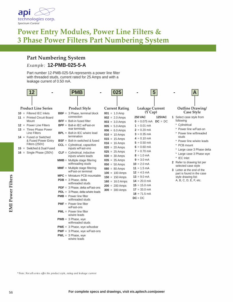
EMI Pow
er Filters
56 For complete specs and drawings, visit eis.apitech.com/power
Power Entry Modules, Power Line Filters &3 Phase Power Filters Part Numbering System
Product Line Series10 = Filtered IEC Inlets11 = Printed Circuit Board
Mount12 = Power Line Filters13 = Three Phase Power
Line Filters14 = Fused or Switched
& Fused Power Entry Filters (250V)
15 = Switched & Dual Fused16 = Single Phase (250V)
Product StyleBBF = 3 Phase, terminal block
connectionBFF = Bolt-in fused filterBPF = Bolt-in IEC w/Fast-on
rear terminalsBPL = Bolt-in IEC w/wire lead
terminationBSF = Bolt-in switched & fusedCCL = Cylindrical, capacitive
inputs w/Fast-onsCLF = Cylindrical, inductive
inputs w/wire leadsMMB = Multiple stage filtering
w/threading studsMMF = Multiple stage filtering
w/Fast-on terminalMPC = Miniature PCB mountablePDB = 3 Phase, delta
w/threaded studsPDF = 3 Phase, delta w/Fast-onsPDL = 3 Phase, delta w/wire leadsPMB = Power line filter
w/threaded studsPMF = Power line filter
w/Fast-onsPML = Power line filter
w/wire leadsPWB = 3 Phase, wye
w/threaded studsPWE = 3 Phase, wye w/busbarPWF = 3 Phase, wye w/Fast-onsPWL = 3 Phase, wye
w/wire leads
Current Rating001 = 1.0 Amp002 = 2.0 Amps003 = 3.0 Amps005 = 5.0 Amps006 = 6.0 Amps010 = 10 Amps015 = 15 Amps016 = 16 Amps020 = 20 Amps025 = 25 Amps030 = 30 Amps035 = 35 Amps050 = 50 Amps080 = 80 Amps100 = 100 Amps150 = 150 Amps160 = 16.0 Amps200 = 200 Amps300 = 300 Amps
Leakage Current (Y Cap)
250 VAC 125VAC0 = 0.075 mA DC = DC1 = 0.01 mA2 = 0.20 mA3 = 0.35 mA4 = 0.10 mA5 = 0.50 mA6 = 0.60 mA7 = 0.70 mA8 = 1.0 mA9 = 3.0 mA10 = 2.0 mA11 = 1.5 mA12 = 4.5 mA13 = 9.0 mA14 = 20.0 mA15 = 15.0 mA17 = 33.0 mA18 = 71.5 mADC = DC
Outline Drawing/Case Style
1 Select case style from following* Cylindrical* Power line w/Fast-on* Power line w/threaded studs
* Power line w/wire leads* PCB mount* Large case 3 Phase delta* Large case 3 Phase wye* IEC Inlet
2 Refer to drawing list per selected case style
3 Letter at the end of the part is found in the case style drawing list: A, B, C, D, E, F, etc.
12 - PMB - 025 - 5 - A
Part Numbering SystemExample: 12-PMB-025-5-APart number 12-PMB-025-5A represents a power line filterwith threaded studs, current rated for 25 Amps and with aleakage current of 0.50 mA.
* Note: Not all series offer the product style, rating and leakage current
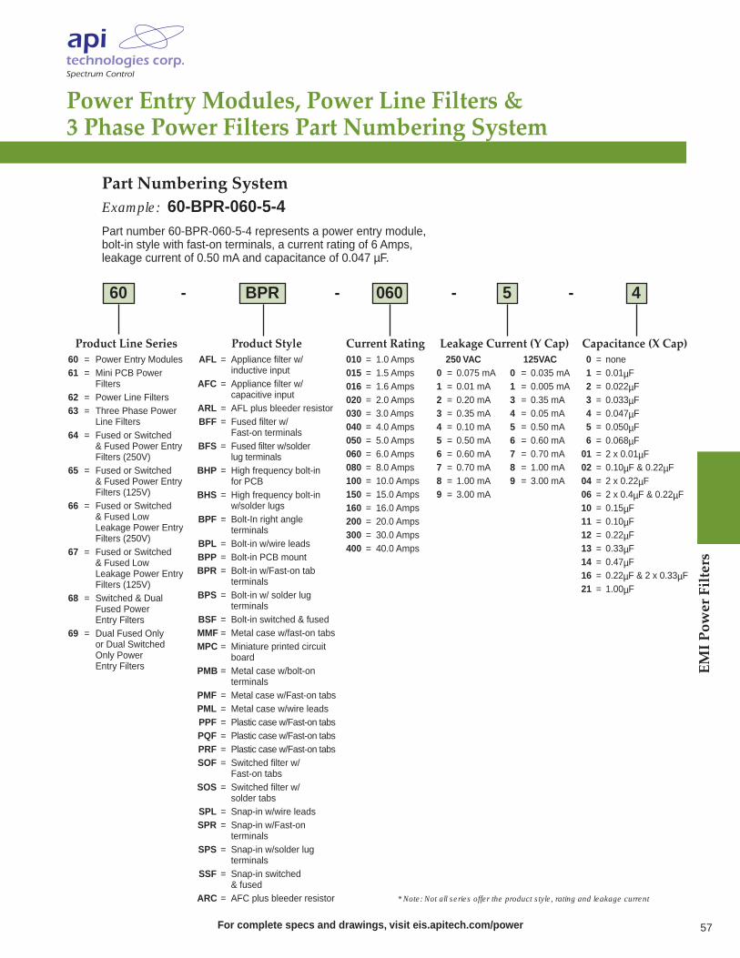
Power Entry Modules, Power Line Filters & 3 Phase Power Filters Part Numbering System
Product Line Series60 = Power Entry Modules61 = Mini PCB Power
Filters62 = Power Line Filters63 = Three Phase Power
Line Filters64 = Fused or Switched
& Fused Power Entry Filters (250V)
65 = Fused or Switched & Fused Power Entry Filters (125V)
66 = Fused or Switched & Fused Low Leakage Power Entry Filters (250V)
67 = Fused or Switched & Fused Low Leakage Power Entry Filters (125V)
68 = Switched & Dual Fused Power Entry Filters
69 = Dual Fused Only or Dual Switched Only Power Entry Filters
60 - BPR - 060 - 5 - 4
Product StyleAFL = Appliance filter w/
inductive inputAFC = Appliance filter w/
capacitive inputARL = AFL plus bleeder resistorBFF = Fused filter w/
Fast-on terminalsBFS = Fused filter w/solder
lug terminalsBHP = High frequency bolt-in
for PCBBHS = High frequency bolt-in
w/solder lugsBPF = Bolt-In right angle
terminalsBPL = Bolt-in w/wire leadsBPP = Bolt-in PCB mountBPR = Bolt-in w/Fast-on tab
terminalsBPS = Bolt-in w/ solder lug
terminalsBSF = Bolt-in switched & fusedMMF = Metal case w/fast-on tabsMPC = Miniature printed circuit
boardPMB = Metal case w/bolt-on
terminalsPMF = Metal case w/Fast-on tabsPML = Metal case w/wire leadsPPF = Plastic case w/Fast-on tabsPQF = Plastic case w/Fast-on tabsPRF = Plastic case w/Fast-on tabsSOF = Switched filter w/
Fast-on tabsSOS = Switched filter w/
solder tabsSPL = Snap-in w/wire leadsSPR = Snap-in w/Fast-on
terminalsSPS = Snap-in w/solder lug
terminalsSSF = Snap-in switched
& fusedARC = AFC plus bleeder resistor
Current Rating010 = 1.0 Amps015 = 1.5 Amps016 = 1.6 Amps020 = 2.0 Amps030 = 3.0 Amps040 = 4.0 Amps050 = 5.0 Amps060 = 6.0 Amps080 = 8.0 Amps100 = 10.0 Amps150 = 15.0 Amps160 = 16.0 Amps200 = 20.0 Amps300 = 30.0 Amps400 = 40.0 Amps
Leakage Current (Y Cap)250 VAC 125VAC
0 = 0.075 mA 0 = 0.035 mA1 = 0.01 mA 1 = 0.005 mA2 = 0.20 mA 3 = 0.35 mA3 = 0.35 mA 4 = 0.05 mA4 = 0.10 mA 5 = 0.50 mA5 = 0.50 mA 6 = 0.60 mA6 = 0.60 mA 7 = 0.70 mA7 = 0.70 mA 8 = 1.00 mA8 = 1.00 mA 9 = 3.00 mA9 = 3.00 mA
Capacitance (X Cap)0 = none1 = 0.01µF2 = 0.022µF3 = 0.033µF4 = 0.047µF5 = 0.050µF6 = 0.068µF01 = 2 x 0.01µF02 = 0.10µF & 0.22µF04 = 2 x 0.22µF06 = 2 x 0.4µF & 0.22µF10 = 0.15µF11 = 0.10µF12 = 0.22µF13 = 0.33µF14 = 0.47µF16 = 0.22µF & 2 x 0.33µF21 = 1.00µF
Part Numbering SystemExample: 60-BPR-060-5-4Part number 60-BPR-060-5-4 represents a power entry module,bolt-in style with fast-on terminals, a current rating of 6 Amps,leakage current of 0.50 mA and capacitance of 0.047 µF.
* Note: Not all series offer the product style, rating and leakage current
For complete specs and drawings, visit eis.apitech.com/power 57
EMI Pow
er Filters

EMI Pow
er Filters
58 For complete specs and drawings, visit eis.apitech.com/singleline
DC Series
11: 10nF-100nF, DC FT
21: 47nF-470nF, DC FT
31: 100nF-1,000nF, DC FT
41: 470nF-4,700nF, DC FT
20: 10nF-470nF, DC Pi
29: 100nF-4,700nF, DC Pi
AC Series
16: 2.2nF-100nF, AC FT
26: 4.7nF-220nF, AC FT
36: 47nF-4,700nF, AC FT
46: 100nF-1,000nF, AC FT
37: 4.7nF-100nF, AC FT
19: 10nF-470nF, AC FT
Single Line Feed-ThroughPower Filters
API Technologies’ Spectrum Control brand of standard and custom feed-through product line is available in a widerange of AC/DC current and voltage rating and addressesEMI filter needs for high current power applications. Circuitstyles of Pi and C are included in the series with maximum current rating to 500 A and capacitance values to 4.7µF. A comprehensive range of AC and DC feed-through filterscan achieve performance from 100 KHz to 10 GHz.
This product is ideal for applications within telecommunications, industrial, medical, avionic and military equipment including cellular base station, industrial processing, secure communications, defensesystems and robotics where high current switching mayoccur. These components also offer a compact economicsolution for any type of EMI issues.
52F22 6 – 0 41 – 63
SLFT Part Numbering SystemExample: 52F226-041-63Represents a DC feed-through capacitor with a very high capacitance (470 nF) 63 A current rating.
Frequency
6: 50/60Hz*
SLFT Series
F: RoHS
Termination Type
0: Threaded Terminals*
Cap Range/Voltage Code
* Indicates agency approved option
Rated Current(Amps)
10163263100200250300
Features Low cost EMI solution
Effective EMI performance from 100 kHz through 1.0 GHz
Designed for bulkhead mounting, proper installation with a low impedance path from the mounting surface to case recommended for optimum performance
Suitable for 0 - 400 Hz applications
External discharge resistor recommended in application
Operating temperature range: -40°C to +85°C without derating
Can be used in both indoor and outdoor applications
Excellent filtering in compact package
Current ratings to 300 A
Custom assemblies available upon request
AC and DC models with Class Y4 caps
C and Pi Configurations
Bolt-in style with D-shaped bushing for easy installation
UL approved and SEMKO approvals pending

Commercial-Off-The-Shelf(COTS) Filters
API Technologies’ Spectrum Control brand now offersCOTS single line feed-through EMI filters that are the commercial equivalent to M15733-PRF/72, M15733-PRF/73 and M15733-PRF/74. These reliable AC and DChigh performance filters meet all the requirements of the QPL equivalent. The filters provide an excellent source of filtering in a compact package and are well suited for the military and aerospace industries. They filter up to 500 A with an attenuation of 40 to 90 dB from 1 MHZ to 1 GHz and voltage rating of 130 VDC to 250 VAC.
MIL part M15733/ Our Commercial Equivalent72-0034 5004-7053-100-A72-0046 5004-7053-100-A72-0049 5004-7059-100-A72-0053 5004-7065-100-A73-0034 5004-7058-125-A73-0043 5004-7053-100-A73-0043 5004-7058-125-A73-0046 5004-7052-125-A73-0049 5004-7058-125-A73-0051 5004-7059-250-A73-0053 5004-7064-125-A74-0030 5004-7041-250-A74-0036 5004-7047-250-A74-0042 5004-7053-250-A74-0045 5004-7059-250-A
P/N Series Configuration* Description52-1490 1 x 5 1 x 5 A, 277 VAC
1 x 30 1 x 30 A, 277 VAC1 x 100 1 x 100 A, 277 VAC1 x 150 1 x 150 A, 277 VAC1 x 200 1 x 200 A, 277 VAC1 x 225 1 x 225 A, 277 VAC2 x 0.5 Speaker Filter2 x 1 ALRM Fire Alarm Filter2 x 5 2 x 5 A, 277 VAC2 x 20 2 x 20 A, 277 VAC2 x 30 2 x 30 A, 277 VAC2 x 50 2 x 50 A, 277 VAC2 x 60 2 x 60 A, 277 VAC
* Add to P/N series (eg. 52-1490-1x5)
Options are available with or without discharge light “L” at the end of thepart (52-1490-1x5L). Custom configurations are available. Consult factory.
Shielded FiltersAPI has developed a new power filter product line which provides MRI/RF shielding solutions for medical,commercial and government applications. Offers 100 dB insertion loss per MIL-STD 220 from 14 KHz to 10 GHZ.
Shielded Room Filters
For complete specs and drawings, visit eis.apitech.com/singleline 59
EMI Pow
er Filters

EMI Pow
er Filters
60 For complete specs and drawings, visit eis.apitech.com/multi
Military/Aerospace Multisection Filters
API Technologies’ Spectrum Control brand will address virtually any requirement for a military/custom power product. Our engineering expertise and vertical integrationsreduce your speed to market as well as saves you money.Our electromagnetic compatibility expertise in the tempestarena can help you meet MIL-F-15733 and MIL-STD 461standard requirements.
Features High common and differential mode attenuation
Standard designs up to 400 Amps
Excellent insertion loss characteristics up to 10 GHz
Voltage rating 115-250VAC and 400VDC up to 400 Hz
Available to meet TEMPEST and FCC requirements
Custom designs for application-specific requirements
Applications Military
Commercial and military/aerospace
Secured communications
Switching power supplies
Data processing equipment
Ruggedized computers
Radar
Electronic warfare
Ground/air weapon systems
Satellites
Ship board systems
Land based vehicles
Fixed and mobile control stations
OrderTest of Examination Test Method Post TestGroup Test or Test (Per MIL-STD-202) Requirements
1 Voltage Drop Paragraph 4.6.8 of MIL-F-15733 Three percent of rated voltage max.
2 Leakage Current UL 1283 Per applicable specification
3 Temperature Rise MIL-F-15733 Paragraph 4.6.4 25°C max.
4 Terminal Strength Method 211, Condition ANo evidence of loosening or rupture.5 lb. applied force. Line Cords: 35 Lbs.
1 Shock, Medium Impact Method 213, Condition G Must pass DWV and Insertion Loss
2 Vibration, High Frequency Method 204, Condition A Monitor for shorts or open
3 Thermal Shock Method 107, Test Condition A Pass 90% DWV IR to be 30% of initial
4 HumidityMethod 107, Condition B, except
Pass 90% DWV IR to be 30% of initialtemperature equals 25°C
1 LifeMethod 108, Condition D 1.2 x Rated AC voltage Pass 90% DWV insulation resistanceat max. operating temp. or 1.4 x DC voltage to be 30% of initial.
IIA
IIB
III
Test SpecificationsThe high performance power line filters shown on pages 62 and 63 are designed to meet the following criteria.
The information shown can be used as a basis for filter specifications. (Contact factory for additional details).
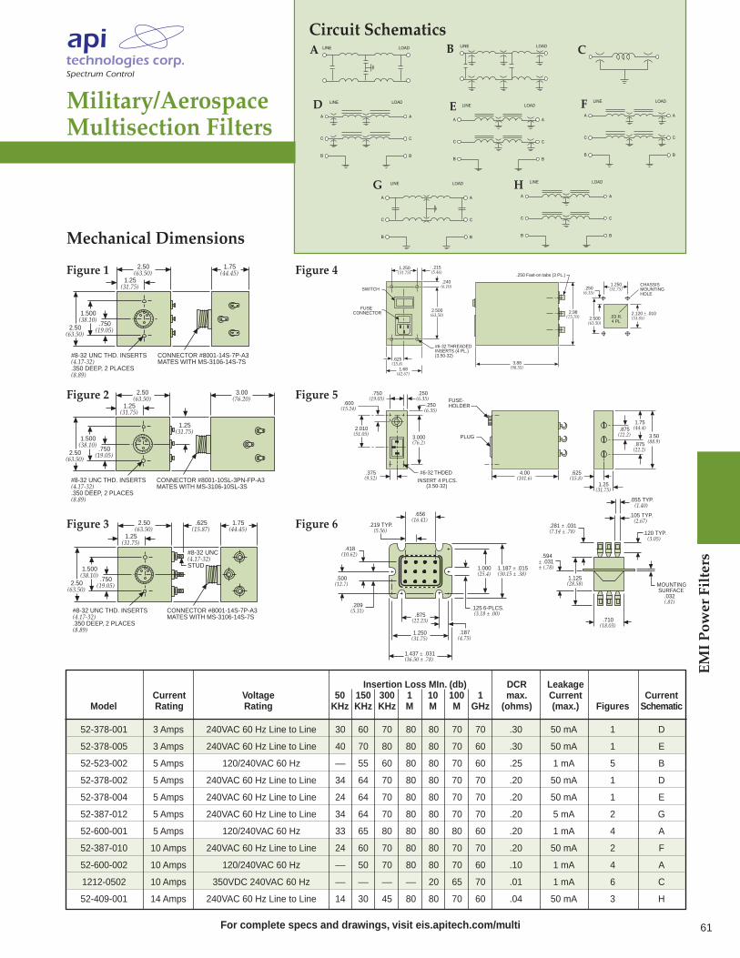
Military/Aerospace Multisection Filters
Mechanical Dimensions
52-378-001 3 Amps 240VAC 60 Hz Line to Line 30 60 70 80 80 70 70 .30 50 mA 1 D
52-378-005 3 Amps 240VAC 60 Hz Line to Line 40 70 80 80 80 70 60 .30 50 mA 1 E
52-523-002 5 Amps 120/240VAC 60 Hz –– 55 60 80 80 70 60 .25 1 mA 5 B
52-378-002 5 Amps 240VAC 60 Hz Line to Line 34 64 70 80 80 70 70 .20 50 mA 1 D
52-378-004 5 Amps 240VAC 60 Hz Line to Line 24 64 70 80 80 70 70 .20 50 mA 1 E
52-387-012 5 Amps 240VAC 60 Hz Line to Line 34 64 70 80 80 70 70 .20 5 mA 2 G
52-600-001 5 Amps 120/240VAC 60 Hz 33 65 80 80 80 80 60 .20 1 mA 4 A
52-387-010 10 Amps 240VAC 60 Hz Line to Line 24 60 70 80 80 70 70 .20 50 mA 2 F
52-600-002 10 Amps 120/240VAC 60 Hz –– 50 70 80 80 70 60 .10 1 mA 4 A
1212-0502 10 Amps 350VDC 240VAC 60 Hz –– –– –– –– 20 65 70 .01 1 mA 6 C
52-409-001 14 Amps 240VAC 60 Hz Line to Line 14 30 45 80 80 70 60 .04 50 mA 3 H
Insertion Loss MIn. (db) DCR LeakageCurrent Voltage 50 150 300 1 10 100 1 max. Current Current
Model Rating Rating KHz KHz KHz M M M GHz (ohms) (max.) Figures Schematic
.215(5.46)
1.250(31.75)
.240(6.10)
2.500(63.50)
SWITCH
FUSECONNECTOR
.625(15.8)
1.68(42.67)
#6-32 THREADEDINSERTS (4 PL.)(3.50-32)
2.98(75.70)
.250 Fast-on tabs (3 PL.)
3.88(98.55)
.03 R. 4 PL
CHASSISMOUNTINGHOLE
2.120 ± .010(53.85) 2.500
(63.50)
1.250(31.75) .250
(6.35)
.600 (15.24)
.750 (19.05)
.250 (6.35)
.250 (6.35)
3.000 (76.2)
2.010 (51.05)
.375 (9.52)
#6-32 THDED
INSERT 4 PLCS. (3.50-32)
.625 (15.8)
1.25 (31.75)
3.50 (88.9) .875
(22.2)
.875 (22.2)
1.75 (44.4)
4.00 (101.6)
PLUG
FUSE-HOLDER
1.437 ± .031(36.50 ± .78)
.875(22.23)
1.250(31.75)
.187(4.75)
.209(5.31)
.418(10.62)
.500(12.7)
.219 TYP.(5.56)
.656(16.41)
.125
1.000(25.4)
1.187 ± .015(30.15 ± .38)
(3.18 ± .00)6-PLCS.
.281 ± .031(7.14 ± .78)
.055 TYP.(1.40)
.105 TYP.(2.67)
.120 TYP. (3.05)
MOUNTING SURFACE .032
(.81)
.710(18.03)
.594± .031± (.78)
1.125(28.58)
.750(19.05)
1.500(38.10)
2.50(63.50)
#8-32 UNC THD. INSERTS(4.17-32).350 DEEP, 2 PLACES(8.89)
1.25(31.75)
2.50(63.50)
CONNECTOR #8001-14S-7P-A3MATES WITH MS-3106-14S-7S
1.75(44.45)
.750(19.05)
1.500(38.10)
2.50(63.50)
#8-32 UNC THD. INSERTS(4.17-32).350 DEEP, 2 PLACES(8.89)
1.25(31.75)
2.50(63.50)
CONNECTOR #8001-10SL-3PN-FP-A3MATES WITH MS-3106-10SL-3S
3.00(76.20)
1.25(31.75)
.750(19.05)
1.500(38.10)
2.50(63.50)
#8-32 UNC THD. INSERTS(4.17-32).350 DEEP, 2 PLACES(8.89)
1.25(31.75)
2.50(63.50)
.625(15.87)
#8-32 UNC(4.17-32)STUD
CONNECTOR #8001-14S-7P-A3MATES WITH MS-3106-14S-7S
1.75(44.45)
Figure 4
Figure 5
Figure 6
Figure 1
Figure 2
Figure 3
LINE LOAD
A
C
B
A
C
B
LINE LOAD
LINE LOAD
A
C
B
A
C
B
LINE LOAD
A
C
B
A
C
B
LINE LOAD
LINE LOAD
A
C
B
A
C
B
A
C
B
A
C
B
LINE LOAD
A
E
B
F
C
G
D
H
Circuit Schematics
For complete specs and drawings, visit eis.apitech.com/multi
EMI Pow
er Filters
61

EMI Pow
er Filters
62 For complete specs and drawings, visit eis.apitech.com/powersol
EMI Power Filter Solutions
Custom Application-Specific DesignsRarely does a 100% off-the-shelf power filter completely satisfy the mechanical, electrical and power requirements and constraints of a sophisticatedOEM design. Yet for many the term custom is intimidating,implying long lead times and higher costs. At API Technologies, we’re focused on providing a completesolution that takes all factors into consideration.Whether modifying an existing power filter design, working from a “clean sheet” approach, or integratingvarious technologies into a subassembly, the resultingcustom solution will be a Spectrum Control brand product tailored to your project’s design, logistic and budgetary requirements.
Application - Specific Options EMI filtering
Power distribution
Transient protection
Indicator lights
Circuit breaker protection
Leads or studs
Voltage cut-off
Agency approvals
Reverse polarity
EMI Testing…Finding the ProblemIntegral to finding a solution to an EMC problem is theability to test for compliance. We conduct a wide range of EMC and environmental tests to help us identify potential problems and recommend design solutions.Our extensive in-house test capabilities allow for a faster turnaround of your complete design solution and lower total cost.
In-house anechoic chamber and shielded room
Baseline of device under ambient-free anechoic chamber
NARTE certified engineering staff
Highly accurate computer controlled instrumentation accumulates and presents data in multiple formats
Testing for MIL standards, European emissions and immunity regulations, and FCC Part 15 (market specific detail on following pages).
We can “clean up” your system by creating an easy-to-install assembly that contains all the components and filtering solutions in one compact package.
.01 .1 1 10
50
70
90
110
130
Customer Design
FREQUENCY (MHz)
Inse
rtio
n Lo
ss (d
B)
.01 .1 1 10
40
60
80
100
120
FREQUENCY (MHz)
Inse
rtio
n Lo
ss (d
B)
API Solution

Ruggedized construction and design flexibility allow our filters to meet demanding environmental and performance requirements
High reliability filters with low-leakage and nonmagnetic options meet EN testing requirements
EMI Power Filter Solutions
Military and AerospaceAPI Technologies has a long history of partnering with leading suppliers of the defense industry. Our ability to find solutions to suppress or eliminate electromagnetic interference (EMI) allows us to provide the high reliability filters required for military and aerospace applications. API’s Spectrum Control brand can design your custom filter with a unique mechanical package for those unusual or tight fittingspaces, higher performance filtering and the voltage rating you need to address all of your AC and DC power issues.
CommunicationsAPI’s Spectrum Control line of power filter solutions can create an agency-approved product that will filter and condition the power to your communications infrastructure equipment, as well as eliminate emissions that can contaminate your distributed AC and DC power.Our custom power filters will incorporate all the componentsand the filtering in one complete package to save you space,time and money. And as a vertically integrated supplier, API offers global low cost manufacturing which allows usto produce fast prototypes and a quicker time to market.
MedicalOur many years of experience in providing EMI/RFI solutions has given us the know-how to design products to meet the specific constraints and requirements of themedical industry. Much of the medical equipment usedtoday requires complete suppression of any and all EMI, as well as low-leakage, nonmagnetic properties to prevent negatively affecting surrounding equipment.We will design and build a high reliability, high performance custom power filter to meet your system and all EN requirements.
IndustrialAt API, we do everything from package design and metalworking to EMI filtering to EMC testing,which means a lower cost for you. Our engineers will design and build a custom power filter that will satisfy global EMC regulations, improve speed-to-market times, overcome space constraints and withstand harsh environmental conditions. Our plug-and-play designs cover a range of industrial and instrumentation applicationsthat will address any of your power filtering needs with current ratings as high as 500 Amps.
Unique mechanical packages addressing specific size and space constraints
Customized and fully integrated assemblies incorporating filters, circuit components and connectors
Custom application-specific filters that meet MIL standard environmental conditions
Designs with selective line filtering, high voltagesand agency approvals
Complex, multifunctionaldesigns that incorporate the filtering and custom circuitry into one easy to install package
Vertically integrated solutions include packaging, circular connectors and filter plates
Compact, space-saving assembly optimized for the welding industry
For complete specs and drawings, visit eis.apitech.com/powersol
EMI Pow
er Filters
63

Power Film Capacitors
API Technologies’ Spectrum Control brand introduces itsnew line of power film capacitors, designed using the latestfilm technology to achieve maximum capacitance density. Available in application-specific packages and terminations,these new power film capacitors feature rugged constructionto withstand even the harshest environments.
Features and Specifications Metallized: polyester, polypropylene and polyphenylene sulphide film dielectrics
Temperature ratings -55°C up to + 150°C
Low ESR and ESL construction
Rugged construction for even the harshest environments
In-house electrical, environmental and reliability testing verification
Standard designs up to 10,000 VDC/ 750 VAC
Standard capacitance values up to 10,000 µF
Ripple currents up to 400 Arms
Applications Renewable energy inverters – solar converters, wind turbines and fuel cells
Electric vehicle power conversion and battery chargers
Aircraft power conversion systems
Radar systems, laser pulse power
Industrial welders, elevators, rail traction drives
High voltage power supplies, switching power supplies
Medical imaging equipment, defibrillators
Model Features & Ordering Information Example: 55PP-600-153-K
55PP – 600 – 106 – K
Voltage Code
600 = 600 VDC
Power PolypropyleneCapacitor Series
Capacitance Code*
153 = 0.015 µF
Tolerance**
K = 10%
High Power Capacitor Series Metalized polypropylene, low loss
Flame retardant tape wrap and epoxy end fill
Axial leads or tab termination
Low ESL & ESR design for high ripple currents
Temperature -55°C to +105°C
Voltages up to 2,000 VDC
Capacitance 0.015 µF to 3.3 µF
* Capacitance in Picofarads. The first two digits are significant and the third represents the number of zeros.
** Indicates standard tolerance. Others available upon request.EMI Pow
er Filters
64 For complete specs and drawings, visit eis.apitech.com/film

For complete specs and drawings, visit eis.apitech.com/film
EMI Pow
er Filters
65
55DC-901-321-XX 900 320 90 97 2.1 50 60 0.8055DC-901-441-XX 900 440 90 120 1.8 60 60 1.0055DC-901-561-XX 900 560 90 145 2.1 60 60 1.1055DC-901-681-XX 900 680 90 170 2.5 80 60 1.3055DC-112-221-XX 1100 220 90 97 2.5 50 60 0.9055DC-112-281-XX 1100 280 90 120 2.1 50 60 1.2055DC-112-361-XX 1100 360 90 145 1.9 60 60 1.3055DC-112-421-XX 1100 420 90 170 2.3 80 60 1.3055DC-132-161-XX 1300 160 90 97 2.1 50 60 0.8055DC-132-211-XX 1300 210 90 120 1.9 50 60 1.0055DC-132-251-XX 1300 250 90 145 2.5 60 50 1.2055DC-132-321-XX 1300 320 90 170 2.8 80 53 1.30
Part Rated Voltage Capacitance D Diameter Height H Typ ESR Typ ESL Irms Max. WeightNumber (VDC) (µF) (mm) (mm) (mOhms) (nH) (A) M (kg)
55DC Link SeriesPower Film Capacitors
API’s Spectrum Control line of high reliability DC link capacitors are ideal for power inverter applications which require superior life under harsh operatiing conditions, such as electric vehicle power conversions, battery chargers, aircraft power conversion systems and radar systems. Featuring a compact and cost-effective design, DC link capacitors are manufactured from segemented, self-healing metallized polypropylene, resulting in longer life expectancy (+100,000 hrs). With high capacitance density and ripple current capabilities, API’s DC link capacitors are the ideal replacement for electrolytic capacitors.
Specifications Capacitance range: 160 µF to 680 µF standard (others available upon request)
Capacitance tolerance: +/- 10% standard
Rated voltage: 900 to 1300 VDC
Operating temperature range: -55°C to +85°C standard (+105°C upon special request)
Test voltage between terminals: 150% rated voltage for 10 sec
Test voltage between terminals and housing: 5kVDC for 10 sec
Enclosure/construction: aluminum housing, brass terminals with dry resin, UL 94V-0 encapsulant
Low ESR and ESL
RoHS compliant
55DC Link Series Part Numbering System
32 or 45 MM
M12 x 1.75 THREAD
90 +2 MM-0 MM
ø20.8 MM(2 PLCS)
M8 x 1.25 THREAD(2 PLCS) 6 ±1 MM
(2 PLCS)
H ±2.00 MM
16±1MM
20 ±1 MM
32 or 45 MM
6 ±1 MM
(2 PLCS)
H ±2.00MM
M5 x 0.8 THREAD5 MM DEEP MIN.
(2 PLCS)
M12 x 1.75 THREAD 16 ±1MM
90 +2 MM-0 MM
ø20.8 MM(2 PLCS)
32 or 45 MM
6 ±1 MM
(2 PLCS)
H ±2.00MM
M6 x 1.0 THREAD10 MM DEEP MIN.
(2 PLCS)
M12 x 1.75 THREAD16 ±1MM
90 +2 MM-0 MM
ø20.8 MM(2 PLCS)
DimensionsM Configuration F Configuration
S Configuration
– = Segmented
S = Standard(non-segmented)
– = M12 stud
N = No M12 stud
55DC – 901 – 321 – XX
Series Voltage
901 = 900 VDC
112 = 1100 VDC
132 = 1300 VDC
Capacitance
321 = 320 µF
441 = 440 µF
MA = M8 External Thread,32mm center-center
FA = M5 Internal Thread, 32mm center-center
SA = M6 Internal Thread, 32 mm center-center
Terminal Code
M = M8 External Thread,45mm center-center
F = M5 Internal Thread,45mm center-center
S = M6 Internal Thread,45mm center-center

Audio Film Capacitors
Features Multiple dielectric options
Metalized film and film/foil construction
Wrap and fill, encapsulated and hermetic options
Multiple lead configurations, tape and epoxy colors
Ability to wind 2-10 layers in a single pass
Ability to provide 4-12 micron film
Wide range of sized up to 2.000" D x 4.250" L
Custom designs available
Benefits Application matching for best performance and cost
Consistent and repeatable, producing high quality components in smaller package size
Improved productivity and increased voltage capability
Excellent performance especially for audio applications
Tighter tolerance to help meet critical application requirement for capacitance and voltage
Hermetic option provides enhanced protection for use in harsh environments
EMI Pow
er Filters
66 For complete specs and drawings, visit eis.apitech.com/film
Metallized Film 10 - 25 kMΩ • µFPolyester -55 to +85°C 50 - 600 N/A 0.001 - 15 µF 1.0% or 40 - 60 kMΩ, -6 to +15% 0.6% Low cost
w/e less
Film - Foil 50 kMΩ • µF
Polyester -55 to +85°C 100 - 600 N/A 0.001 - 5 µF 0.5% or 100 kMΩ, -6 to +15% 0.6% Low costw/e less
Metallized 504 @ 60 Hz 200 kMΩ • µF
Polypropylene -55 to +85°C 200 - 600 115 @ 1 kHz 0.001 - 8 µF 0.2% or 400 kMΩ, -4 to +2% 0.1% Low DFw/e less
Film-Foil 250 kMΩ • µF
Polypropylene -55 to +85°C 100 - 600 AC Capable 0.001 - 1 µF 0.1% or 500 kMΩ, -4 to +2% 0.1% Low DFw/e less
Metallized 25 - 50 kMΩ • µF High temp
Polyphenylene -55 to +125°C 50 - 600 240 @ 60 Hz 0.001 - 10 µF 0.3 - 0.5% or 50 - 100 kMΩ, ±2% 0.2% capability
Sulfide 160 @ 1 kHz w/e less No voltagederating
25 - 50 kMΩ • µF High tempMetallized -55 to +125°C 50 - 600 240 @ 60 Hz 0.001 - 10 µF 0.3 - 0.5% or 50 - 100 kMΩ, ±2% 0.2% capability
Polycarbonate 160 @ 1 kHz w/e less No voltagederating
100 kMΩ • µF High tempMetallized -55 to +170°C 50 - 5000 AC Capable 0.0047 - 0.1% or 200 kMΩ, -6 to +15% 0.06% capabilityTeflon 10 µF w/e less Electrical
characteristics
Capacitor Operating WVD WVAC Capacitance DF Insulation TC DA Key Type Temperature C Range Resistance Features

67
MagneticsCustom Magnetic SolutionsWe offer extensive design and manufacturing capabilities, including more than two dozen magnetic core materials andwinding wire from 6 to 45 gauge with many coatings, leads and terminations. We produce toroids ranging in size from 0.5" to 18" in diameter with up to 4,000 turns and accuracy to +/- 1 turn, and a wide variety of encapsulation and laminateoptions. Below are some of the critical design criteria we will work with your engineering team to address.
Electrical Characteristics - Identifying the circuit function/application and/or specifying electrical requirements such as amperage, voltage, inductance, frequency response, leakage, and noise reduction often determines selection of materials and components.
Mechanical Constraints - Restrictions on maximum heightand available board area and mounting style (surface mount or through-hole) set physical parameters that often are difficult to change. Mechanical size restrictions can strongly affect component temperature rise.
Environmental Conditions - Maximum/minimum operatingtemperatures and allowed surface and/or internal temperaturesof components, including UL compliance, as well as conditionssuch as air flow, sealing of container, high shock, and vibrationwill influence material selection and design.
Regulating Requirements - Considerations include safetystandards to be met (eg. IEC/UL 60950-1, UL61010-1, UL1585 etc), listing of the unit with a regulatory agency such asUL, CSA or VDE and requirements for UL thermal insulationsystem marking.
Qualification Conditions - Identify the qualification processrequired prior to approval, be it customer standards, or Hi-Relstandards such as MIL-PRF-27 or MIL-STD-981 and whetherformal testing or the ability to demonstrate compliance by design is necessary.
For complete specs and drawings, visit eis.apitech.com/magnetics
we offer a variety of transformers, inductors,choke, coils and custom solutions to meet your magnetics needs
Our magnetics group combines the people, productsand technologies of several brands, including Filtranand RTI Electronics, in order to satisfy your magneticsrequirements. API Technologies is a key supplier tomany of the world’s leading OEMs, serving the military,aerospace, medical, telecom, transport, RF and industrial/test measurement markets.
Quality ConstructionAPI’s commitment to quality begins with a rigorous raw material selection and inspection process and continuesthrough highly trained operators utilizing state-of-the-artequipment. The end result are the highest quality magnetics consistently manufactured to meet some of the industry's most stringent requirements includingmany MIL, ANSI and ISO certifications.

Magnetics
Current TransformersCurrent Sensors Measures electrical current (AC & DC) and can transform current from high to low measurable values
Wide primary current range of 3.5 Amps to 800 Amps Apps include advanced fault tolerant computers and workstations, control panels reading current flowing to electric transformer, telecom and communications
High Frequency Current Transformers 20 kHz-100 kHz operating frequency Available totally encapsulated, with or without wound primary turns and loading resistor
Built to UL, MIL, VDE, CE specs, EMRL current transformers meet UL1244
Ideal for ampmeters, wattmeters, relays and cross current compensation
Magnetics
For complete specs and drawings, visit eis.apitech.com/magnetics
Load Detector Current Sensors Innovative Snap-On load detectors mount on pre-wired systems without disrupting existing connections
Broad frequency response of 30Hz to 15 kHz Measure currents up to 40 Amps RMS continuous and 120 Amps intermittent
Excellent for economical energy management and automation control
Power Inductors/Chokes Precision wound heavy-duty toroidal inductors Stores energy as a magnetic field, can delay and reshape alternating current
Up to 100 amps, standard Semi or full epoxy molded, horizontal and vertical mounting Lighting dimmers – low wattage residential to higher wattage commercial, motor controls, SCR controls and line filters
Switch Mode Power Supply Inductors Filter inductors, toroidal current sense transformers and high frequency inverter transformers
Performance verified in 25kHz power supply 10 to 1,000 watts with low power losses Switching frequencies from 5 to 100 kHz Open winding, semi-encapsulated and encapsulated construction
Custom designs up to 200 Amps
Lighting Chokes & Inductor/Filters Precision wound heavy-duty toroidal inductors Rugged design 120 volt models from 12.5 to 100 Amps 240 volt models from 8.3 to 60 Amps High quality noise rejection filter Ideal for lighting dimmers, EMI/RFI filters, PWM and PM circuits primarily for motor controls, UPS Systems, differential mode line filters
68
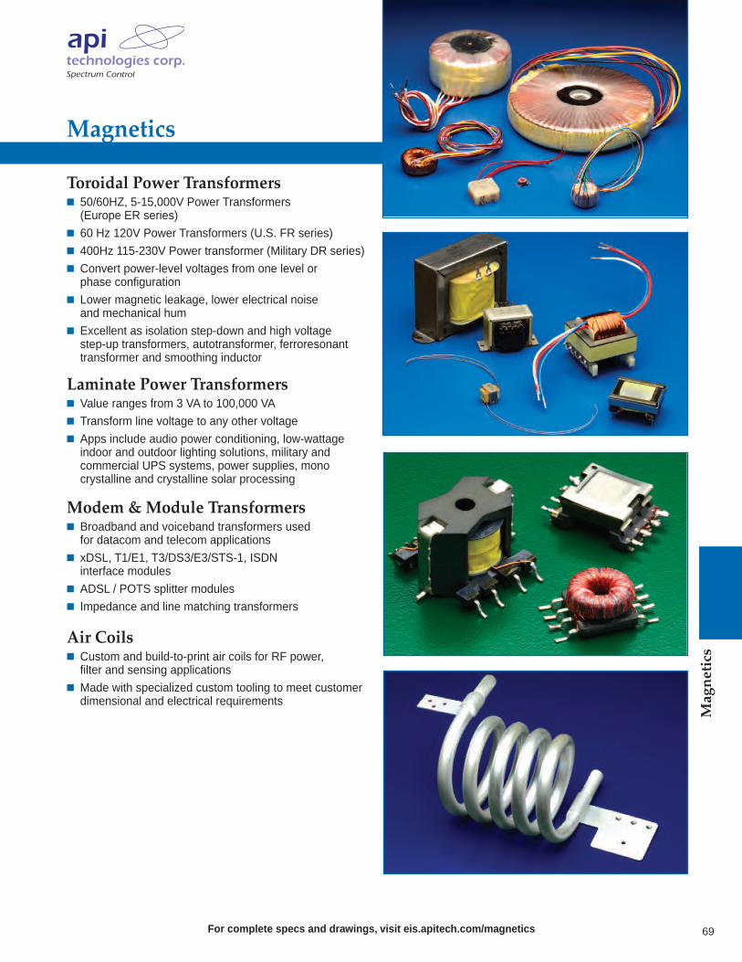
For complete specs and drawings, visit eis.apitech.com/magnetics
Magnetics
69
Magnetics
Toroidal Power Transformers 50/60HZ, 5-15,000V Power Transformers (Europe ER series)
60 Hz 120V Power Transformers (U.S. FR series) 400Hz 115-230V Power transformer (Military DR series) Convert power-level voltages from one level or phase configuration
Lower magnetic leakage, lower electrical noise and mechanical hum
Excellent as isolation step-down and high voltage step-up transformers, autotransformer, ferroresonant transformer and smoothing inductor
Laminate Power Transformers Value ranges from 3 VA to 100,000 VA Transform line voltage to any other voltage Apps include audio power conditioning, low-wattage indoor and outdoor lighting solutions, military and commercial UPS systems, power supplies, mono crystalline and crystalline solar processing
Modem & Module Transformers Broadband and voiceband transformers used for datacom and telecom applications
xDSL, T1/E1, T3/DS3/E3/STS-1, ISDN interface modules
ADSL / POTS splitter modules Impedance and line matching transformers
Air Coils Custom and build-to-print air coils for RF power, filter and sensing applications
Made with specialized custom tooling to meet customer dimensional and electrical requirements

+1 855.294.3800www.apitech.com
AHA 2M 11/14 27-0027-0117 ©2014 API Technologies Corp. Printed in U.S.A.
integratedsolutions
electromagnetic
Sales OfficesNORTH AMERICA8061 Avonia RoadFairview, Pennsylvania 16415Phone: 814-474-1571Fax: 814-474-3110
EUROPESpectrum Control GmbHHansastrasse 691126 Schwabach, GermanyPhone: (49)-9122-795-0Fax: (49)-9122-795-58
CHINASpectrum Control Limited2nd Industrial AreaLing Tou Industrial RoadQiad Tou Town, Dong Guan CityGuang Dong Province 523530Peoples Republic of ChinaPhone: (011)-86-769-8343-7761Fax: (011)-86-769-8343-7760
eis.apitech.com
• EMI Filters• Filtered Interconnects• Ceramic Capacitors
CERTIFIED
CERTIFIED
About API Technologies API Technologies Corp. is a trusted provider of RF/microwave, microelectronics, and security solutions for critical and high-reliability
applications. The company designs, develops and manufactures electronic components, modules, systems and products for technically demanding defense, commercial/industrial and aerospace applications. API Technologies’ customers include many leading
Fortune 500 companies, as well as a majority of NATO governments. While API was founded in 1981, our heritage brands have served the demanding, hi-rel marketplace for more than 60 years. API Technologies trades on the NASDAQ under the symbol ATNY.
Power & Systems Solutions
Sensors Solutions
RF/Microwave & Microelectronics
Electromagnetic Integrated Solutions
Electronics Manufacturing Services
Secure Systems & Information Assurance
• Specialty Connectors• Power Filters & Capacitors• Magnetics


![HMC960LP4E - Elecfansfile.elecfans.com/web1/M00/00/58/o4YBAFnMXgWAOq71... · [2] Output common mode voltage range is specified for worst case temperature, supply voltage, and bias](https://img.pdfslide.us/doc/110x75/5ea5eba818faec1c610f2b0d/hmc960lp4e-2-output-common-mode-voltage-range-is-specified-for-worst-case-temperature.jpg)