Embed Size (px)
Citation preview
I N T E G R AT E D D R I L L I N G S Y S T E M U S I N G M U D AC T UAT E D
D OW N H O L E H A M M E R A S P R I M A RY E N G I N E
R E P O R T # 3 4 3 6 5 R 0 5
FINAL TECHNICAL REPORT Reporting period start date 9/30/97 Reporting period end date 9/01/05
AUTHORS: JOHN V. FERNANDEZ, DAVID S. PIXTON REPORT DATE: DECEMBER 2005
D O E A W A R D N U M B E R : D E - F C 2 6 - 9 7 F T 3 4 3 6 5
2185 South Larsen Parkway Provo , UT 84606
ii
D i s c l a i m e r
This report was prepared as an account of work sponsored by an agency of the United States Government. Neither the United States Government nor any agency thereof, nor any of their employees, makes any warranty, express or implied, or assumes any legal liability or responsibility for the accuracy, completeness, or usefulness of any information, apparatus, product, or process disclosed, or represents that its use would not infringe privately owned rights. Reference herein to any specific commercial product, process, or service by trade name, trademark, manufacturer, or otherwise does not necessarily constitute or imply its endorsement, recommendation, or favoring by the United States Government or any agency thereof. The views and opinions of authors expressed herein do not necessarily state or reflect those of the United States Government or any agency thereof.
iii
ABSTRACT
A history and project summary of the development of an integrated drilling system using a mud-actuated down-hole hammer as its primary engine are given. The summary includes laboratory test results, including atmospheric tests of component parts and simulated borehole tests of the hammer system. Several remaining technical hurdles are enumerated. A brief explanation of commercialization potential is included. The primary conclusion for this work is that a mud actuated hammer can yield substantial improvements to drilling rate in overbalanced, hard rock formations. A secondary conclusion is that the down-hole mud actuated hammer can serve to provide other useful down-hole functions including generation of high pressure mud jets, generation of seismic and sonic signals, and generation of diagnostic information based on hammer velocity profiles.
TABLE OF CONTENTS
Table of Contents..................................................................... iii
Background ................................................................................1
System Description ...................................................................4
Experimental ............................................................................14
Results & Discussion ..............................................................20
Commercialization Plans........................................................29
Conclusions & Recommendations .......................................30
References.................................................................................31
NOVATEK 2185 SOUTH LARSEN PAR KWAY, PROVO, UT 84606 (801) 374-6000
1
I N T E G R AT E D D R I L L I N G S Y S T E M GRANT DE-FC26-97FT34365
BACKGROUND
Overall project objectives & scope
Novatek and the U.S. Department of Energy (DOE) have engaged in Cooperative Agreement DE-FC26-97FT34365 to further develop a down hole mud actuated hammer and investigate its use as the primary engine for powering a variety of down hole drilling functions.
Historically, the primary justification for developing a mud actuated hammer has been the potential it offers to reduce drilling costs through increasing rate-of-penetration (ROP) of the drill bit, increasing bit life, and decreasing unwanted hole deviation. However, having a linear hammer “engine” operating down hole can provide several other important benefits. For example, the hammer can be used to generate pulsed high pressure mud jets that augment the mechanical drilling action of the drill bit. These mud jets may be generated by a simple extension to the hammer drilling system, namely, pistons that are driven by the linear motion of the hammer. Similarly, other key components of the drilling process could be enhanced using the linear oscillating action of the mud driven hammer, such as steering, feedback on formation properties, and communications.
In this broader context, the down-hole mud hammer may be seen as the primary engine for an integrated, self-contained drilling system. Much like an automobile engine serving as the power source for driving an alternator, power steering unit, water pump, air conditioning system, etc., the hammer can be used to make the drilling process largely self-contained, or at least greatly simplified. Such a system would eliminate redundant power transmission systems, thus reducing system size and cost and improving overall drilling system reliability. Reduced system size would also allow simpler control of the drilling head, and greater responsiveness to desired trajectory changes.
In the above-mentioned cooperative agreement, Novatek proposed to investigate four such drilling functions that could be accomplished or augmented by the reciprocating action of the down-hole mud actuated hammer: 1) down-hole bit rotation, 2) sensing and control, 3) data transmission and 4) directional drilling. In addition, work under the agreement included an analysis of the field-worthiness of the tool and of the hammer’s effectiveness as an ROP enhancer. Various improvements to the basic machine were to be implemented and tested in this latter effort.
It was beyond the scope of the current program to complete the integration of the drilling system with the full suite of sophisticated electronic equipment required for integrated operation of all system components. It was similarly outside of the scope to attempt to optimize the life and configuration of each of the component parts. However, the outlined work was intended to prove the fundamental concepts behind a hammer driven drilling system, and thereby move to the next level of industry attention.
The ultimate objective of the technology has been to enable substantial improvement in overall drilling productivity by helping drillers to not only reach their target more quickly, but also have the control and feedback necessary to reach the target more precisely.
NOVATEK 2185 SOUTH LARSEN PAR KWAY, PROVO, UT 84606 (801) 374-6000
2
Development history
In 1997, Novatek set out to develop an integrated drilling system that would offer significant cost reduction and technical advantage over current drilling practice, particularly in deep, medium-to-hard rock formations. This drilling system was based around a mud-actuated down-hole hammer of which Novatek had previously built working prototypes and had deployed in a limited number of field test wells. A year-long paper study at the beginning of the project compared various candidate technologies for the integrated drilling system and helped narrow the focus of the development program to those concepts most worthy of pursuit. This first phase of work was then followed by a second phase wherein candidate technologies were studied more closely and laboratory prototypes were built and tested. The purpose of this second phase was to identify and address practical and theoretical hurdles, and further refine designs to prepare them for eventual field use. Using the concepts considered fruitful after the second phase of work, further development proceeded in a third phase. In parallel with all of this work, testing of the basic hammer continued and various design changes were investigated in an effort to improve hammer performance and facilitate the implementation of the integrated drilling system concepts.
Through this process, the concepts deemed worthy of further development that were directly related to the hammer were identified as: a) steering the drill bit using a phased, pulsed mud jet; b) use of hammer impact energy to create a seismic signal while drilling; and c) sensing rock characteristics using hammer rebound motion measurements. Use of the hammer reciprocation to effect drill bit rotation, and use of the hammer impact energy for data telemetry were both concluded to not be beneficial uses of the hammer. In the case of drill bit rotation, the need for precise weight-on-bit (WOB) control to keep the system within available torque limits, the attendant risk of stalling of the whole system (rotation and percussion) in the well, and the emergence of successful rotary steerable systems that do not rely on down-hole rotation for steering, were factors leading to the conclusion that hammer-actuated drill bit rotation was not fruitful to pursue. In the case of data telemetry, Novatek concluded that a much higher data bandwidth was needed by the oil and gas industry than could be delivered by either existing mud pulse technology or a new hammer acoustic telemetry system. This is particularly true when considering the needs for real time data to support seismic while drilling.
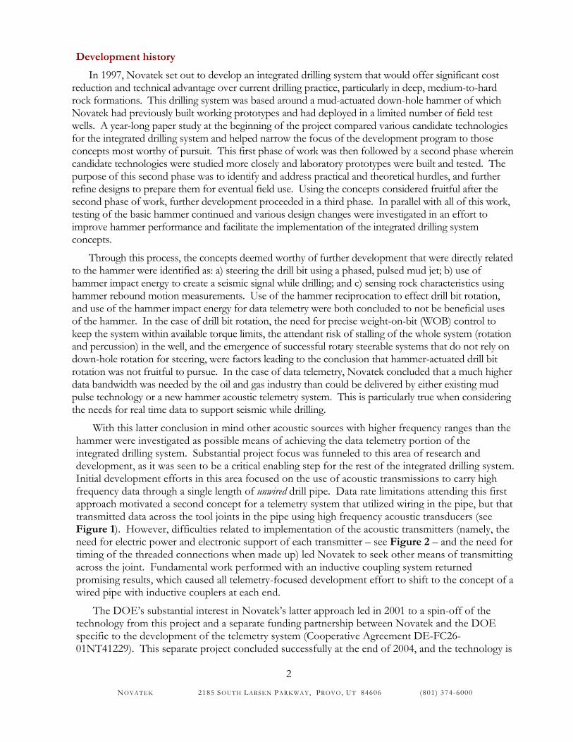
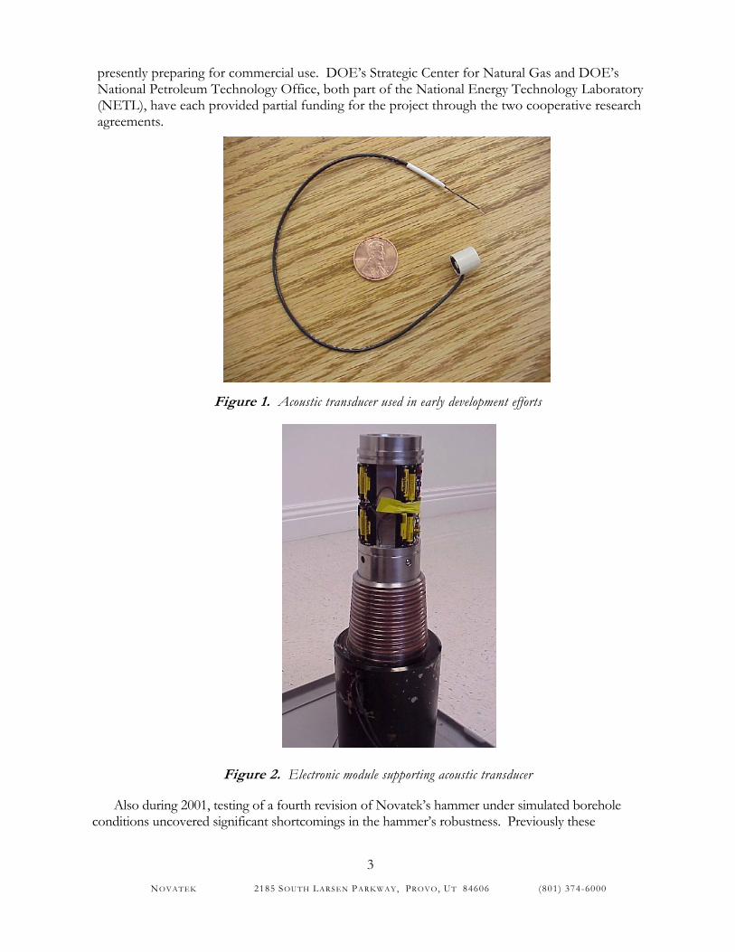
With this latter conclusion in mind other acoustic sources with higher frequency ranges than the hammer were investigated as possible means of achieving the data telemetry portion of the integrated drilling system. Substantial project focus was funneled to this area of research and development, as it was seen to be a critical enabling step for the rest of the integrated drilling system. Initial development efforts in this area focused on the use of acoustic transmissions to carry high frequency data through a single length of unwired drill pipe. Data rate limitations attending this first approach motivated a second concept for a telemetry system that utilized wiring in the pipe, but that transmitted data across the tool joints in the pipe using high frequency acoustic transducers (see Figure 1). However, difficulties related to implementation of the acoustic transmitters (namely, the need for electric power and electronic support of each transmitter – see Figure 2 – and the need for timing of the threaded connections when made up) led Novatek to seek other means of transmitting across the joint. Fundamental work performed with an inductive coupling system returned promising results, which caused all telemetry-focused development effort to shift to the concept of a wired pipe with inductive couplers at each end.
The DOE’s substantial interest in Novatek’s latter approach led in 2001 to a spin-off of the technology from this project and a separate funding partnership between Novatek and the DOE specific to the development of the telemetry system (Cooperative Agreement DE-FC26-01NT41229). This separate project concluded successfully at the end of 2004, and the technology is
NOVATEK 2185 SOUTH LARSEN PAR KWAY, PROVO, UT 84606 (801) 374-6000
3
presently preparing for commercial use. DOE’s Strategic Center for Natural Gas and DOE’s National Petroleum Technology Office, both part of the National Energy Technology Laboratory (NETL), have each provided partial funding for the project through the two cooperative research agreements.
Figure 1. Acoustic transducer used in early development efforts
Figure 2. Electronic module supporting acoustic transducer
Also during 2001, testing of a fourth revision of Novatek’s hammer under simulated borehole conditions uncovered significant shortcomings in the hammer’s robustness. Previously these
NOVATEK 2185 SOUTH LARSEN PAR KWAY, PROVO, UT 84606 (801) 374-6000
4
shortcomings had been ignored in favor of proceeding with system optimization work. However, as the optimization process proceeded and further improvements were made to hammer impact levels, robustness problems became more critical. Upon further consideration of the objectives of the project, and after further consultation with the DOE early in 2002, the above-mentioned shortcomings were determined to be of sufficient overall design influence to warrant proceeding with substantial design changes prior to resuming testing and further development of the integrated drilling system components. These design changes to the hammer itself have been the only focus of the program since that time – the more advanced system developments remain suspended in their development.
Design goals
Several design goals were set for the integrated drilling system. These include:
1) 200 hour operational life in mud (implies no mechanical failure or failure by erosion during that time)
2) Operation that is near transparent to rig personnel, i.e., that utilizes existing surface equipment, mud systems, etc.
3) Telemetry data payload of 1 Mbit/sec Specific to the hammer engine, the following goals are established
4) Operation that is reliable and independent of mud viscosity (related to item 2 above) 5) No dead zones for mud to collect and dry when not in use 6) Ability to control hammer frequency and blow energy pseudo-independently of mud
pressure
In the sections following, the hammer design and integrated drilling system resulting from the project is described, together with the experimental methods utilized and the results obtained from testing of the hammer system. In addition, conclusions are drawn about the technical and commercial value of the technologies.
SYSTEM DESCRIPTION
The down-hole integrated drilling system concept
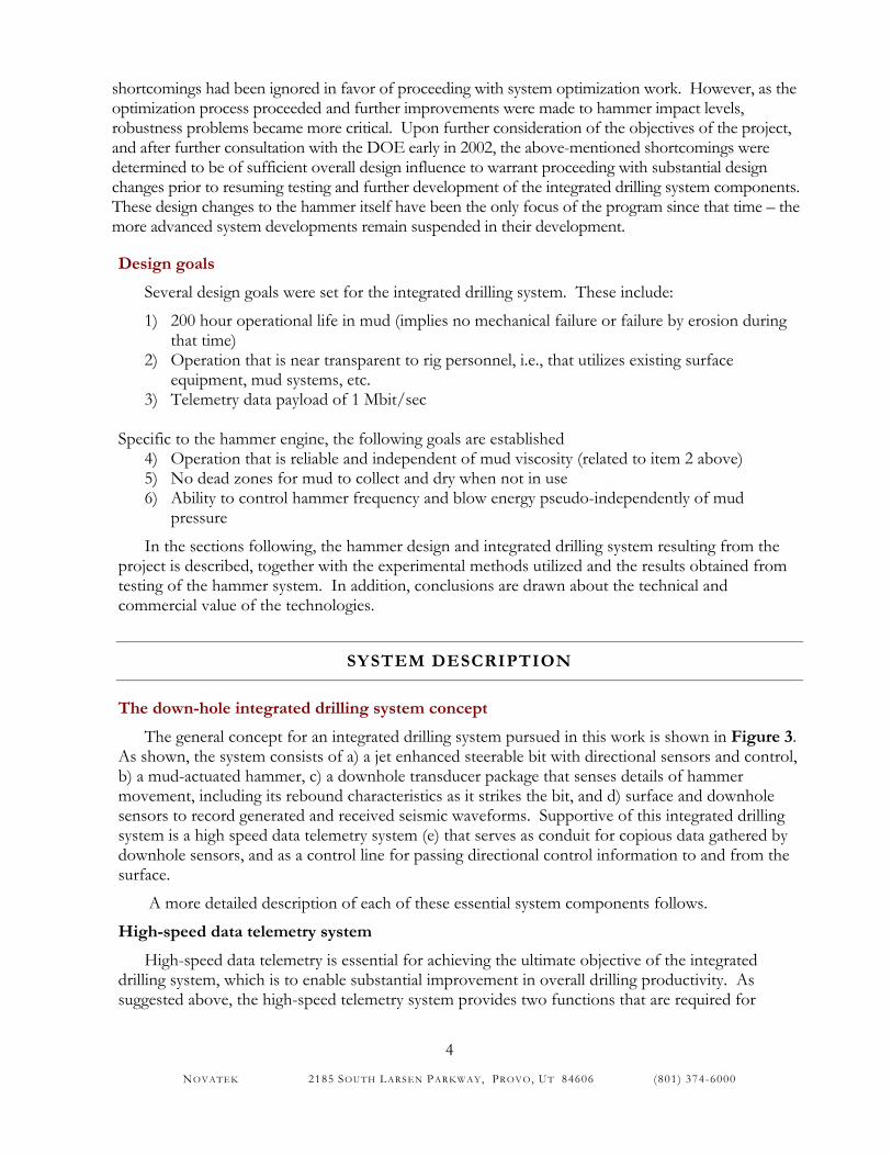
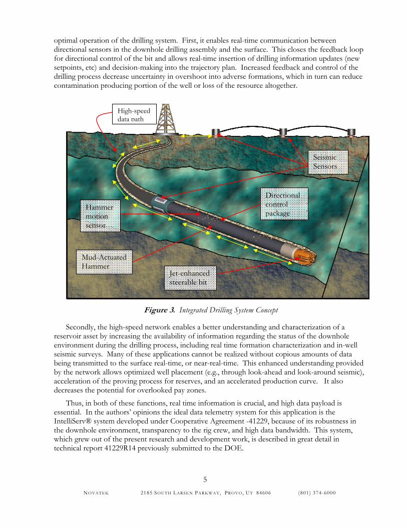
The general concept for an integrated drilling system pursued in this work is shown in Figure 3. As shown, the system consists of a) a jet enhanced steerable bit with directional sensors and control, b) a mud-actuated hammer, c) a downhole transducer package that senses details of hammer movement, including its rebound characteristics as it strikes the bit, and d) surface and downhole sensors to record generated and received seismic waveforms. Supportive of this integrated drilling system is a high speed data telemetry system (e) that serves as conduit for copious data gathered by downhole sensors, and as a control line for passing directional control information to and from the surface.
A more detailed description of each of these essential system components follows.
High-speed data telemetry system
High-speed data telemetry is essential for achieving the ultimate objective of the integrated drilling system, which is to enable substantial improvement in overall drilling productivity. As suggested above, the high-speed telemetry system provides two functions that are required for
NOVATEK 2185 SOUTH LARSEN PAR KWAY, PROVO, UT 84606 (801) 374-6000
5
optimal operation of the drilling system. First, it enables real-time communication between directional sensors in the downhole drilling assembly and the surface. This closes the feedback loop for directional control of the bit and allows real-time insertion of drilling information updates (new setpoints, etc) and decision-making into the trajectory plan. Increased feedback and control of the drilling process decrease uncertainty in overshoot into adverse formations, which in turn can reduce contamination producing portion of the well or loss of the resource altogether.
Figure 3. Integrated Drilling System Concept
Secondly, the high-speed network enables a better understanding and characterization of a reservoir asset by increasing the availability of information regarding the status of the downhole environment during the drilling process, including real time formation characterization and in-well seismic surveys. Many of these applications cannot be realized without copious amounts of data being transmitted to the surface real-time, or near-real-time. This enhanced understanding provided by the network allows optimized well placement (e.g., through look-ahead and look-around seismic), acceleration of the proving process for reserves, and an accelerated production curve. It also decreases the potential for overlooked pay zones.
Thus, in both of these functions, real time information is crucial, and high data payload is essential. In the authors’ opinions the ideal data telemetry system for this application is the IntelliServ® system developed under Cooperative Agreement -41229, because of its robustness in the downhole environment, transparency to the rig crew, and high data bandwidth. This system, which grew out of the present research and development work, is described in great detail in technical report 41229R14 previously submitted to the DOE.
Seismic Sensors
Mud-Actuated Hammer
Jet-enhanced steerable bit
Directional control package
Hammer motion sensor
High-speed data path
NOVATEK 2185 SOUTH LARSEN PAR KWAY, PROVO, UT 84606 (801) 374-6000
6
Jet-enhanced steerable bit
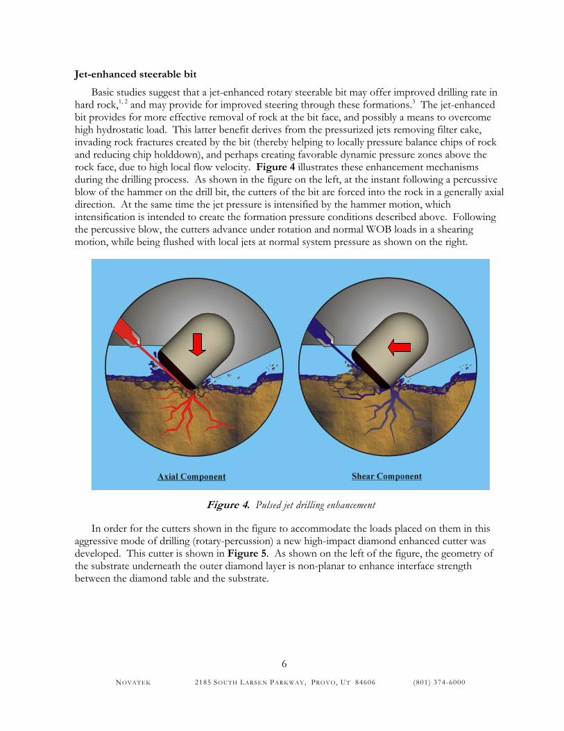
Basic studies suggest that a jet-enhanced rotary steerable bit may offer improved drilling rate in hard rock,1, 2 and may provide for improved steering through these formations.3 The jet-enhanced bit provides for more effective removal of rock at the bit face, and possibly a means to overcome high hydrostatic load. This latter benefit derives from the pressurized jets removing filter cake, invading rock fractures created by the bit (thereby helping to locally pressure balance chips of rock and reducing chip holddown), and perhaps creating favorable dynamic pressure zones above the rock face, due to high local flow velocity. Figure 4 illustrates these enhancement mechanisms during the drilling process. As shown in the figure on the left, at the instant following a percussive blow of the hammer on the drill bit, the cutters of the bit are forced into the rock in a generally axial direction. At the same time the jet pressure is intensified by the hammer motion, which intensification is intended to create the formation pressure conditions described above. Following the percussive blow, the cutters advance under rotation and normal WOB loads in a shearing motion, while being flushed with local jets at normal system pressure as shown on the right.
Figure 4. Pulsed jet drilling enhancement
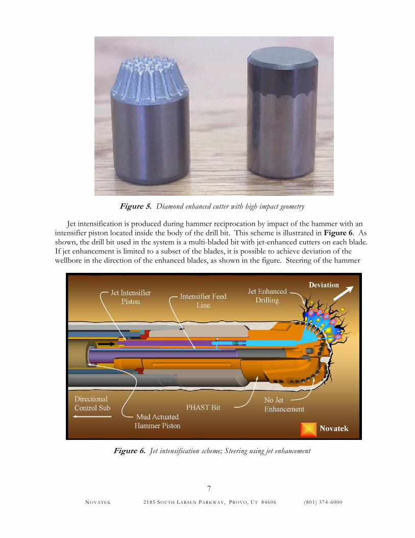
In order for the cutters shown in the figure to accommodate the loads placed on them in this aggressive mode of drilling (rotary-percussion) a new high-impact diamond enhanced cutter was developed. This cutter is shown in Figure 5. As shown on the left of the figure, the geometry of the substrate underneath the outer diamond layer is non-planar to enhance interface strength between the diamond table and the substrate.
NOVATEK 2185 SOUTH LARSEN PAR KWAY, PROVO, UT 84606 (801) 374-6000
7
Figure 5. Diamond enhanced cutter with high impact geometry
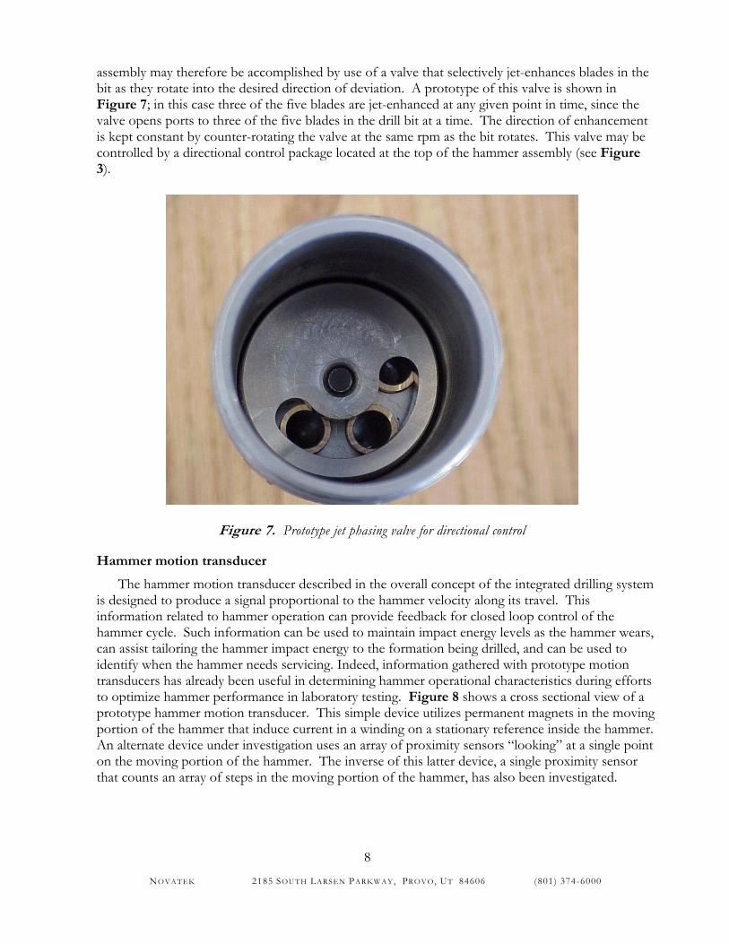
Jet intensification is produced during hammer reciprocation by impact of the hammer with an intensifier piston located inside the body of the drill bit. This scheme is illustrated in Figure 6. As shown, the drill bit used in the system is a multi-bladed bit with jet-enhanced cutters on each blade. If jet enhancement is limited to a subset of the blades, it is possible to achieve deviation of the wellbore in the direction of the enhanced blades, as shown in the figure. Steering of the hammer
Figure 6. Jet intensification scheme; Steering using jet enhancement
NOVATEK 2185 SOUTH LARSEN PAR KWAY, PROVO, UT 84606 (801) 374-6000
8
assembly may therefore be accomplished by use of a valve that selectively jet-enhances blades in the bit as they rotate into the desired direction of deviation. A prototype of this valve is shown in Figure 7; in this case three of the five blades are jet-enhanced at any given point in time, since the valve opens ports to three of the five blades in the drill bit at a time. The direction of enhancement is kept constant by counter-rotating the valve at the same rpm as the bit rotates. This valve may be controlled by a directional control package located at the top of the hammer assembly (see Figure 3).
Figure 7. Prototype jet phasing valve for directional control
Hammer motion transducer
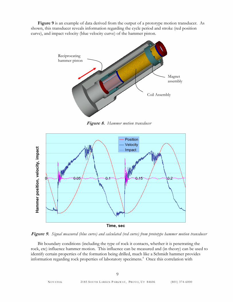
The hammer motion transducer described in the overall concept of the integrated drilling system is designed to produce a signal proportional to the hammer velocity along its travel. This information related to hammer operation can provide feedback for closed loop control of the hammer cycle. Such information can be used to maintain impact energy levels as the hammer wears, can assist tailoring the hammer impact energy to the formation being drilled, and can be used to identify when the hammer needs servicing. Indeed, information gathered with prototype motion transducers has already been useful in determining hammer operational characteristics during efforts to optimize hammer performance in laboratory testing. Figure 8 shows a cross sectional view of a prototype hammer motion transducer. This simple device utilizes permanent magnets in the moving portion of the hammer that induce current in a winding on a stationary reference inside the hammer. An alternate device under investigation uses an array of proximity sensors “looking” at a single point on the moving portion of the hammer. The inverse of this latter device, a single proximity sensor that counts an array of steps in the moving portion of the hammer, has also been investigated.
NOVATEK 2185 SOUTH LARSEN PAR KWAY, PROVO, UT 84606 (801) 374-6000
9
Figure 9 is an example of data derived from the output of a prototype motion transducer. As shown, this transducer reveals information regarding the cycle period and stroke (red position curve), and impact velocity (blue velocity curve) of the hammer piston.
Figure 8. Hammer motion transducer
0 0.05 0.1 0.15 0.2
Time, sec
Ham
mer
pos
ition
, vel
ocity
, im
pact
PositionVelocityImpact
Figure 9. Signal measured (blue curve) and calculated (red curve) from prototype hammer motion transducer
Bit boundary conditions (including the type of rock it contacts, whether it is penetrating the rock, etc) influence hammer motion. This influence can be measured and (in theory) can be used to identify certain properties of the formation being drilled, much like a Schmidt hammer provides information regarding rock properties of laboratory specimens.4 Once this correlation with
Reciprocating hammer piston
Magnet assembly
Coil Assembly
NOVATEK 2185 SOUTH LARSEN PAR KWAY, PROVO, UT 84606 (801) 374-6000
10
formation properties is made, the hammer motion transducer may also increase its usefulness by enhancing formation evaluation. This concept clearly requires further examination.
Seismic/sonic while drilling system
Basic studies have indicated that multi-frequency noise is generated by the operation of the hammer and drill bit. It is possible to use this noise for formation characterization while drilling.5 One potential application for this generated noise would be to permit use of drill bit seismic techniques in any well, including those wells where standard drill bits do not produce a suitable signal. For example, the present drill bit seismic technique is limited to areas where rollercone bits (of a certain geometry) can be used, where WOB is not restricted, and where the formation being drilled is hard enough to create a “noisy” drilling process. In areas where these conditions are not met, the benefits of drill bit seismic cannot be realized. However, with the hammer as a seismic source none of these limitations are present. In fact, the hammer offers further benefits in that it can be controlled to produce a range of output frequencies as needed, which allows more control over the process of gathering seismic data and permits a broader frequency range for study. It should be noted that in this application, it is particularly important to have a high-payload communications path such that the actual hammer vibrations that are transmitted into the formation can be measured downhole and transmitted to the surface for real time correlation with the vibrations received at the surface. Though present drill bit seismic techniques utilize acoustic transmission of the incident waveform up the drillstring for correlation with received waveforms, this technique has the major drawback of being limited by depth and complexity of wellbore (where the signal is attenuated by the acoustic pass band of the drill string and other factors such as contact of the string with the borehole wall). Thus, the hammer, coupled with a high-speed data path offers substantial improvements to the drill bit seismic application.
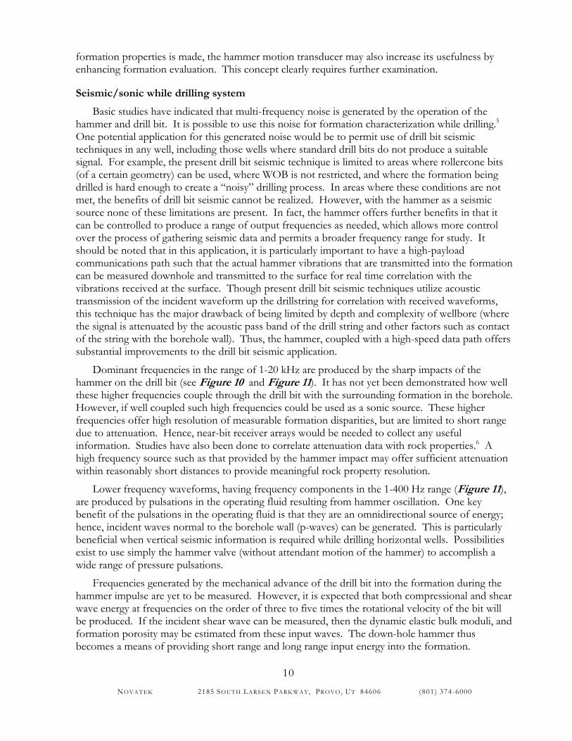
Dominant frequencies in the range of 1-20 kHz are produced by the sharp impacts of the hammer on the drill bit (see Figure 10 and Figure 11). It has not yet been demonstrated how well these higher frequencies couple through the drill bit with the surrounding formation in the borehole. However, if well coupled such high frequencies could be used as a sonic source. These higher frequencies offer high resolution of measurable formation disparities, but are limited to short range due to attenuation. Hence, near-bit receiver arrays would be needed to collect any useful information. Studies have also been done to correlate attenuation data with rock properties.6 A high frequency source such as that provided by the hammer impact may offer sufficient attenuation within reasonably short distances to provide meaningful rock property resolution.
Lower frequency waveforms, having frequency components in the 1-400 Hz range (Figure 11), are produced by pulsations in the operating fluid resulting from hammer oscillation. One key benefit of the pulsations in the operating fluid is that they are an omnidirectional source of energy; hence, incident waves normal to the borehole wall (p-waves) can be generated. This is particularly beneficial when vertical seismic information is required while drilling horizontal wells. Possibilities exist to use simply the hammer valve (without attendant motion of the hammer) to accomplish a wide range of pressure pulsations.
Frequencies generated by the mechanical advance of the drill bit into the formation during the hammer impulse are yet to be measured. However, it is expected that both compressional and shear wave energy at frequencies on the order of three to five times the rotational velocity of the bit will be produced. If the incident shear wave can be measured, then the dynamic elastic bulk moduli, and formation porosity may be estimated from these input waves. The down-hole hammer thus becomes a means of providing short range and long range input energy into the formation.
NOVATEK 2185 SOUTH LARSEN PAR KWAY, PROVO, UT 84606 (801) 374-6000
11
-4
-3
-2
-1
0
1
2
3
4
0 0.05 0.1 0.15 0.2 0.25 0.3 0.35 0.4
time, sec
AccelerationHammer Impulse
Figure 10. Acceleration signature of hammer correlated to impact
0 1.104 2.104 3.104 4.104 5.1040
1
2
3
4
Accelk
fk Figure 11. Frequency spectra of acceleration signature (left) and hammer exhaust pressure (right)
Mud actuated hammer
The heart of the integrated drilling system is the mud-actuated hammer. A primary function of the hammering motion is to create rock breaking mechanisms which increase the rate of penetration particularly through hard rock sections of a formation. As indicated above, when coupled with the jet-enhanced steerable bit, the hammer drilling system may also function like a rotary steerable system, but with the added benefit of the hammering motion and pulsed high-pressure jets. Though the hammer is typically thought of as a tool for hard rock formations, the high-pressure jets generated by the hammer may assist in cleaning the bit in softer formations, which could improve soft formation ROP. As indicated above, the hammer drilling system may also operate beneficially in a non-impact mode, wherein the hammer simply free-cycles within its housing, creating pressure pulsations for certain seismic studies.
0 200 400 600 800 10000
1
2
3
Pexk
fk
NOVATEK 2185 SOUTH LARSEN PAR KWAY, PROVO, UT 84606 (801) 374-6000
12
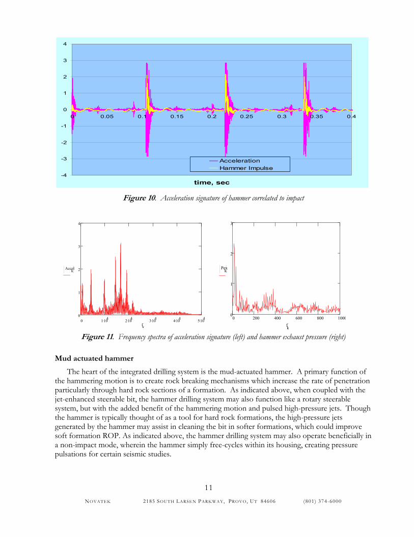
The most current embodiment of the hammer assembly is an electro-hydraulic actuated drilling system that consists of three primary sub-assemblies: a valve assembly (including a control module), a piston assembly and a bit assembly. The three sub-systems together provide the means of efficiently converting fluid power into hammer impacts. The general concept for a mud driven hammer tool is shown in Figure 12.
Figure 12. Mud actuated hammer schematic
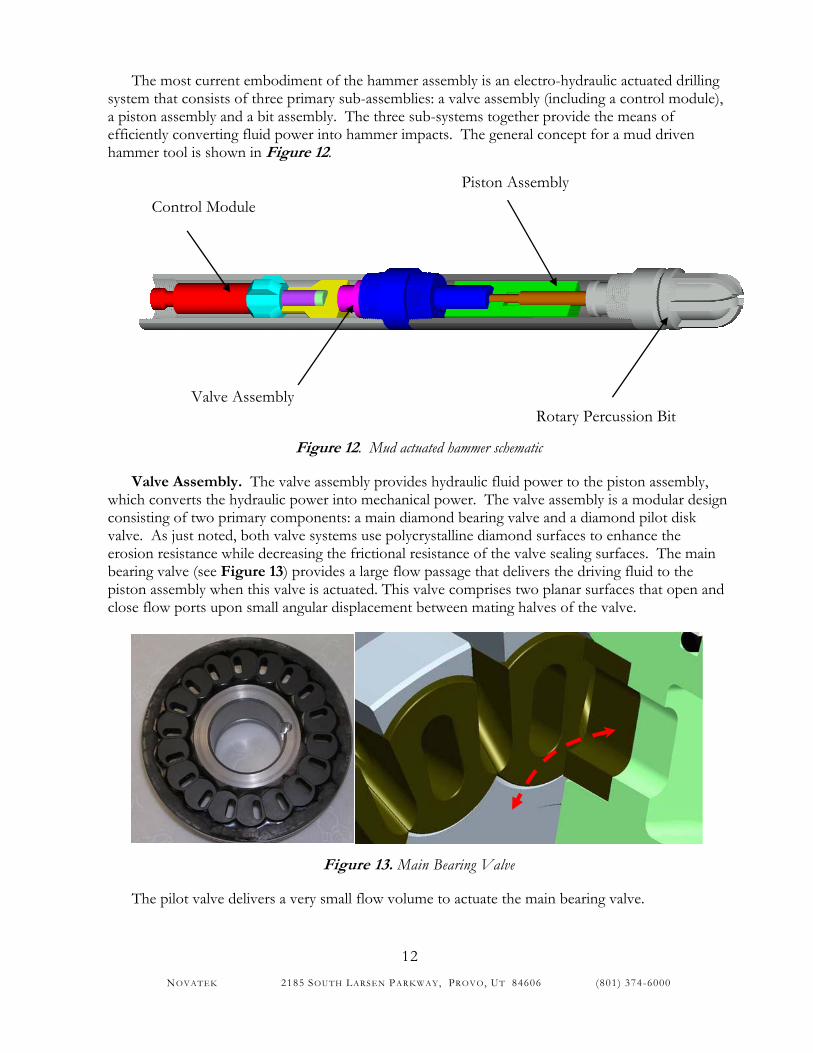
Valve Assembly. The valve assembly provides hydraulic fluid power to the piston assembly, which converts the hydraulic power into mechanical power. The valve assembly is a modular design consisting of two primary components: a main diamond bearing valve and a diamond pilot disk valve. As just noted, both valve systems use polycrystalline diamond surfaces to enhance the erosion resistance while decreasing the frictional resistance of the valve sealing surfaces. The main bearing valve (see Figure 13) provides a large flow passage that delivers the driving fluid to the piston assembly when this valve is actuated. This valve comprises two planar surfaces that open and close flow ports upon small angular displacement between mating halves of the valve.
Figure 13. Main Bearing Valve
The pilot valve delivers a very small flow volume to actuate the main bearing valve.
Valve Assembly
Control Module Piston Assembly
Rotary Percussion Bit
NOVATEK 2185 SOUTH LARSEN PAR KWAY, PROVO, UT 84606 (801) 374-6000
13
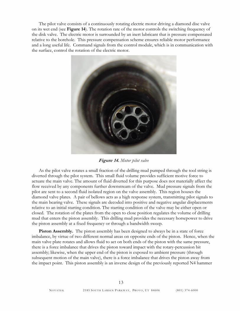
The pilot valve consists of a continuously rotating electric motor driving a diamond disc valve on its wet end (see Figure 14). The rotation rate of the motor controls the switching frequency of the disk valve. The electric motor is surrounded by an inert lubricant that is pressure compensated relative to the borehole. This pressure compensation scheme ensures reliable motor performance and a long useful life. Command signals from the control module, which is in communication with the surface, control the rotation of the electric motor.
Figure 14. Motor pilot valve
As the pilot valve rotates a small fraction of the drilling mud pumped through the tool string is diverted through the pilot system. This small fluid volume provides sufficient motive force to actuate the main valve. The amount of fluid diverted for this purpose does not materially affect the flow received by any components further downstream of the valve. Mud pressure signals from the pilot are sent to a second fluid isolated region on the valve assembly. This region houses the diamond valve plates. A pair of bellows acts as a high response system, transmitting pilot signals to the main bearing valve. These signals are decoded into positive and negative angular displacements relative to an initial starting condition. The starting condition of the valve may be either open or closed. The rotation of the plates from the open to close position regulates the volume of drilling mud that enters the piston assembly. This drilling mud provides the necessary horsepower to drive the piston assembly at a fixed frequency or through a bandwidth sweep.
Piston Assembly. The piston assembly has been designed to always be in a state of force imbalance, by virtue of two different normal areas on opposite ends of the piston. Hence, when the main valve plate rotates and allows fluid to act on both ends of the piston with the same pressure, there is a force imbalance that drives the piston toward impact with the rotary-percussion bit assembly; likewise, when the upper end of the piston is exposed to ambient pressure (through subsequent motion of the main valve), there is a force imbalance that drives the piston away from the impact point. This piston assembly is an inverse design of the previously reported N4 hammer
NOVATEK 2185 SOUTH LARSEN PAR KWAY, PROVO, UT 84606 (801) 374-6000
14
piston, 7 in terms of the directions of the imbalanced forces, and in terms of the location of the normal areas within the piston assembly.
Rotary-Percussion Bit Assembly. The bit developed for the hammer system is most appropriately termed a rotary-percussion bit because it allows drilling of rock via both rotary and percussive rock breakage mechanisms. The bit is a five-bladed design and is arrayed with diamond-enhanced cutters (Figure 5) that are positioned at a high rake angle. The rotary-percussion bit design is advantageous particularly in interbedded hard and soft formations, where purely percussion bits typically have poor overall performance.
Unique aspects of the bit assembly design are the high pressure jets surrounding the forward bit cutters (see above), and the ability to insert instrumentation at the bit-face. For this latter design concept, two sensor pockets have been placed between blades in the bit face. These pockets communicate through a central conduit that runs inside the hammer between the control module and the bit assembly (refer to Figure 12). Possible applications for these pockets include pressure sensors which measure the intensified pressure used to clean and steer the bit, and the mud system pressure just prior to its exit through the bit’s primary nozzles. The pockets could also house accelerometers, which provide indication of the inclination and orientation of the bit. Additionally, measurements of the impact created by the bit and the resultant reflected seismic waves can be recorded.
The impacted portion of the hammer assembly is a single piece construction, utilizing electron beam welding to simplify bit machining. This method of attaching the assembly ensures minimal discontinuities between the piston and the bit, ensuring as much cross-sectional area for impact load transmission.
EXPERIMENTAL
The research and development work completed during the course of the project may be classified into two major divisions: work related to the hammer itself and work related to auxiliary equipment driven by the hammer. Primary tasks in both of these areas included modeling and designing the drilling system, building and testing of bench-scale mockups and prototypes, and building and testing of full-scale prototypes. As indicated above, the second division of work was suspended in 2002 in favor of placing full focus on the first division of work. The focus of the present writing is therefore on the work related specifically to the hammer. Further information on the auxiliary equipment has been presented in various conferences sponsored by the DOE.3, 7, 8
Benchmark testing of hammer revision 4
Preliminary drilling tests were performed in a 100-foot test well filled with high compressive strength concrete (nominal 10,500 psi) under near-atmospheric conditions, using hammer revision 4. This particular revision of the hammer is a 7-3/4” tool with a piston assembly powered by a linearly-sliding shuttle valve,7 which had previously been optimized for efficient generation of impact energy. Baseline drilling rate was determined by drilling with a Reed 8-1/2 inch tricone bit at 60 rpm under 15,000 lbf weight on bit (WOB). Hammer drilling was then accomplished under a nominal 15,000 lbf WOB, using the same tricone bit. Further drilling was then done using the hammer coupled with the Novatek jet-assisted drill bit.
Following these preliminary tests, full-scale drilling tests were performed in a borehole simulator provided by TerraTek, in Salt Lake City, Utah.9 This test was done in cooperation with DOE
NOVATEK 2185 SOUTH LARSEN PAR KWAY, PROVO, UT 84606 (801) 374-6000
15
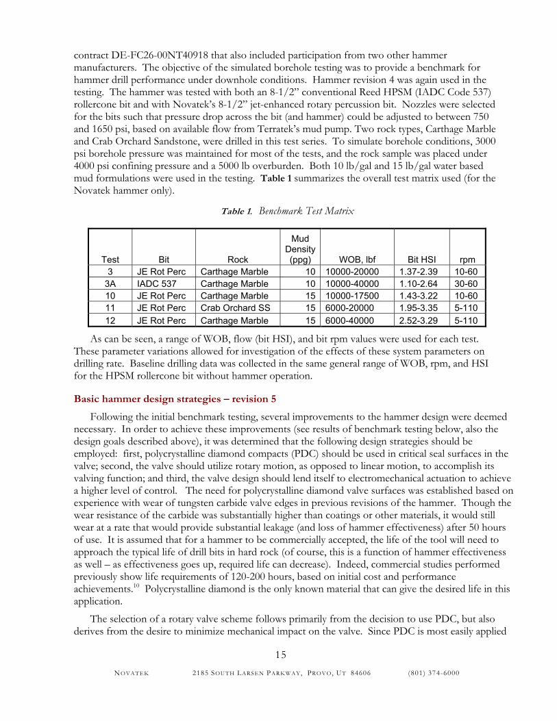
contract DE-FC26-00NT40918 that also included participation from two other hammer manufacturers. The objective of the simulated borehole testing was to provide a benchmark for hammer drill performance under downhole conditions. Hammer revision 4 was again used in the testing. The hammer was tested with both an 8-1/2” conventional Reed HPSM (IADC Code 537) rollercone bit and with Novatek’s 8-1/2” jet-enhanced rotary percussion bit. Nozzles were selected for the bits such that pressure drop across the bit (and hammer) could be adjusted to between 750 and 1650 psi, based on available flow from Terratek’s mud pump. Two rock types, Carthage Marble and Crab Orchard Sandstone, were drilled in this test series. To simulate borehole conditions, 3000 psi borehole pressure was maintained for most of the tests, and the rock sample was placed under 4000 psi confining pressure and a 5000 lb overburden. Both 10 lb/gal and 15 lb/gal water based mud formulations were used in the testing. Table 1 summarizes the overall test matrix used (for the Novatek hammer only).
Table 1. Benchmark Test Matrix
Test Bit Rock
Mud Density (ppg) WOB, lbf Bit HSI rpm
3 JE Rot Perc Carthage Marble 10 10000-20000 1.37-2.39 10-60 3A IADC 537 Carthage Marble 10 10000-40000 1.10-2.64 30-60 10 JE Rot Perc Carthage Marble 15 10000-17500 1.43-3.22 10-60 11 JE Rot Perc Crab Orchard SS 15 6000-20000 1.95-3.35 5-110 12 JE Rot Perc Carthage Marble 15 6000-40000 2.52-3.29 5-110
As can be seen, a range of WOB, flow (bit HSI), and bit rpm values were used for each test. These parameter variations allowed for investigation of the effects of these system parameters on drilling rate. Baseline drilling data was collected in the same general range of WOB, rpm, and HSI for the HPSM rollercone bit without hammer operation.
Basic hammer design strategies – revision 5
Following the initial benchmark testing, several improvements to the hammer design were deemed necessary. In order to achieve these improvements (see results of benchmark testing below, also the design goals described above), it was determined that the following design strategies should be employed: first, polycrystalline diamond compacts (PDC) should be used in critical seal surfaces in the valve; second, the valve should utilize rotary motion, as opposed to linear motion, to accomplish its valving function; and third, the valve design should lend itself to electromechanical actuation to achieve a higher level of control. The need for polycrystalline diamond valve surfaces was established based on experience with wear of tungsten carbide valve edges in previous revisions of the hammer. Though the wear resistance of the carbide was substantially higher than coatings or other materials, it would still wear at a rate that would provide substantial leakage (and loss of hammer effectiveness) after 50 hours of use. It is assumed that for a hammer to be commercially accepted, the life of the tool will need to approach the typical life of drill bits in hard rock (of course, this is a function of hammer effectiveness as well – as effectiveness goes up, required life can decrease). Indeed, commercial studies performed previously show life requirements of 120-200 hours, based on initial cost and performance achievements.10 Polycrystalline diamond is the only known material that can give the desired life in this application.
The selection of a rotary valve scheme follows primarily from the decision to use PDC, but also derives from the desire to minimize mechanical impact on the valve. Since PDC is most easily applied
NOVATEK 2185 SOUTH LARSEN PAR KWAY, PROVO, UT 84606 (801) 374-6000
16
to flat surfaces, a face seal lends itself to PDC enhancement much easier than a diametral seal, such as the shuttled spool used in the previous revision. A rotary face seal, as opposed to an axially oscillating face seal, minimizes impact on the operating face of the valve.
The third strategy, that of enabling electromechanical actuation in the design, was originally selected based on a longer-term objective to make possible tailoring of hammer output characteristics to different geologic formations. However, this strategy was also seen as a means of compensating for changing down-hole conditions (e.g., mud viscosity) without requiring hardware changes; furthermore, electromechanical actuation provides for a much higher degree of control over test variables, enhancing understanding and probability of success in the testing phase.
In addition to these primary improvements, several secondary objectives were conceived for the redesign effort. These include: further improving the flow areas within the tool to reduce fluid-related losses and increase efficiency; decreasing leakage past internal bearings to reduce flow losses and erosive wear; and to increase the impact area of the hammer.
Prototype testing – revision 5
The experimental program used to validate hammer designs consisted of sub-assembly testing of the mechanical and electrical components of the hammer. The mechanical sub-assemblies tested included the valve assembly, bit assembly, and impact piston assembly. All the electric systems embedded in those assemblies, such as sensors and control boards, were simultaneously tested. A data acquisition system was developed to monitor and record relevant parameters during the testing program. The testing of the different assembly components was conducted separately to identify and localize possible areas requiring additional development work. The testing of all sub-assemblies was conducted in parallel, whenever possible, to reduce the development time of the hammer. All the testing work conducted was performed in Novatek’s laboratory or its in-house testing facility. This facility includes a 750 hp duplex mud pump, a 50 bbl mixing tank, a DrillTech drill rig with top drive (60,000 lb pull up and 40-foot stroke), a Scorpion 80,000 ft-lbf make-up tong, a 40’ deep x 3’ diameter uncased well, a 100’ deep x 12” steel cased well (both wells filled with high compressive strength concrete for drilling tests), a 1000’ deep x 12” steel cased well, and a control house with data acquisition equipment.
Performance Metrics. For each of the sub-assemblies tested, the primary goal was to develop a robust downhole hammering system capable of:
1. Efficiently converting the potential energy mud to mechanical work 2. Reliably delivering hammer power to the formation under downhole conditions for the
specified longevity
Test programs were created to address those requirements and characterize the hammer’s capability in achieving those goals.
Bit Assembly Testing Program. The evaluation program for the bit assembly consisted of flow tests which subjected the bit assembly components to high pressure water and water-based mud. All components were examined before and after each test to determine whether a particular test was successful.
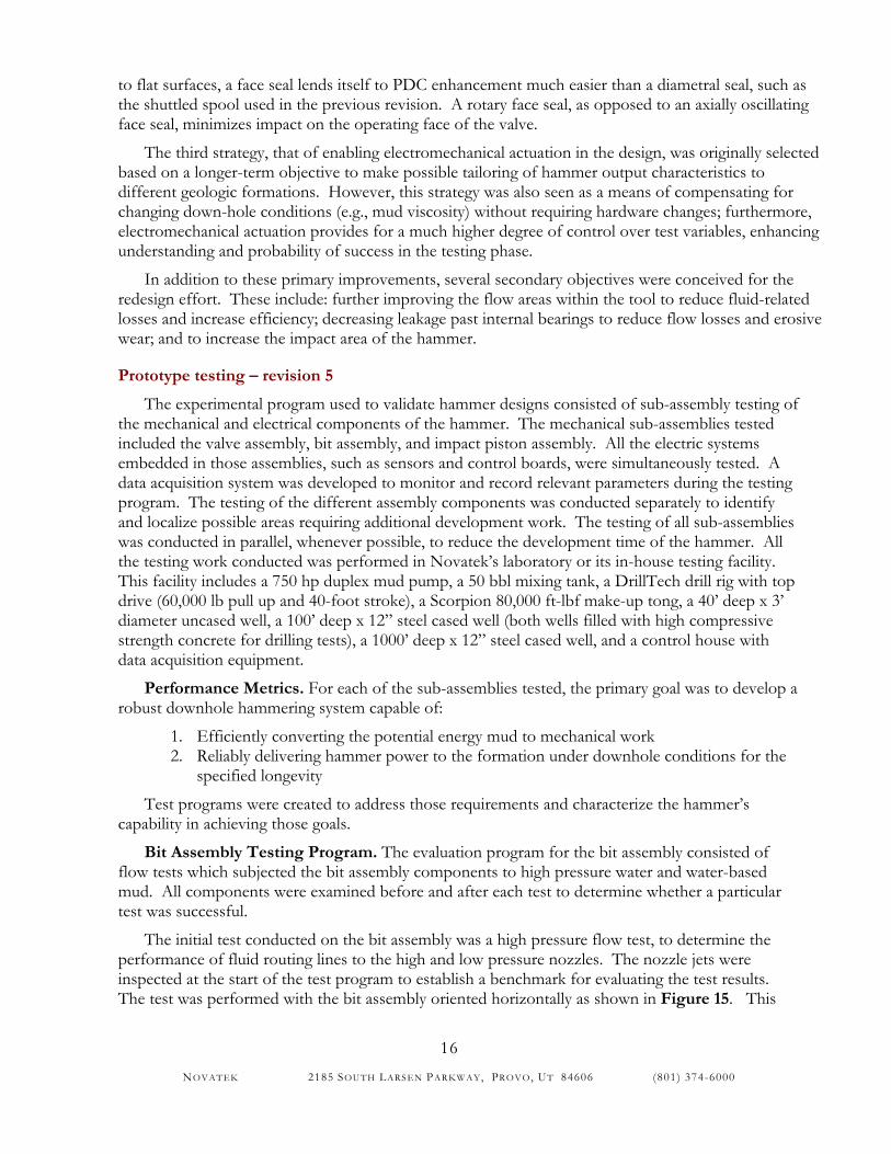
The initial test conducted on the bit assembly was a high pressure flow test, to determine the performance of fluid routing lines to the high and low pressure nozzles. The nozzle jets were inspected at the start of the test program to establish a benchmark for evaluating the test results. The test was performed with the bit assembly oriented horizontally as shown in Figure 15. This
NOVATEK 2185 SOUTH LARSEN PAR KWAY, PROVO, UT 84606 (801) 374-6000
17
test used water at pressure differentials up to 1500 psi. The volume of fluid pumped into the assembly and the fluid volume and pressure exiting the nozzles was recorded.
Upon successful completion of the first test, a second bit assembly test was conducted to determine the fatigue and vibration resistance characteristics of an internal conduit conveying the control wires from the bit to the data acquisition system located in the valve assembly. This test was conducted in the same arrangement as the nozzle test shown in Figure 15. Two types of conduit were tested: Alloy 2205 and AISI 316L, both with 0.035” wall thickness. The conduit was inspected before and after the test to determine the effect of the high pressure waves on the pitch and wall thickness of the coiled conduit.
Figure 15. High pressure nozzle test.
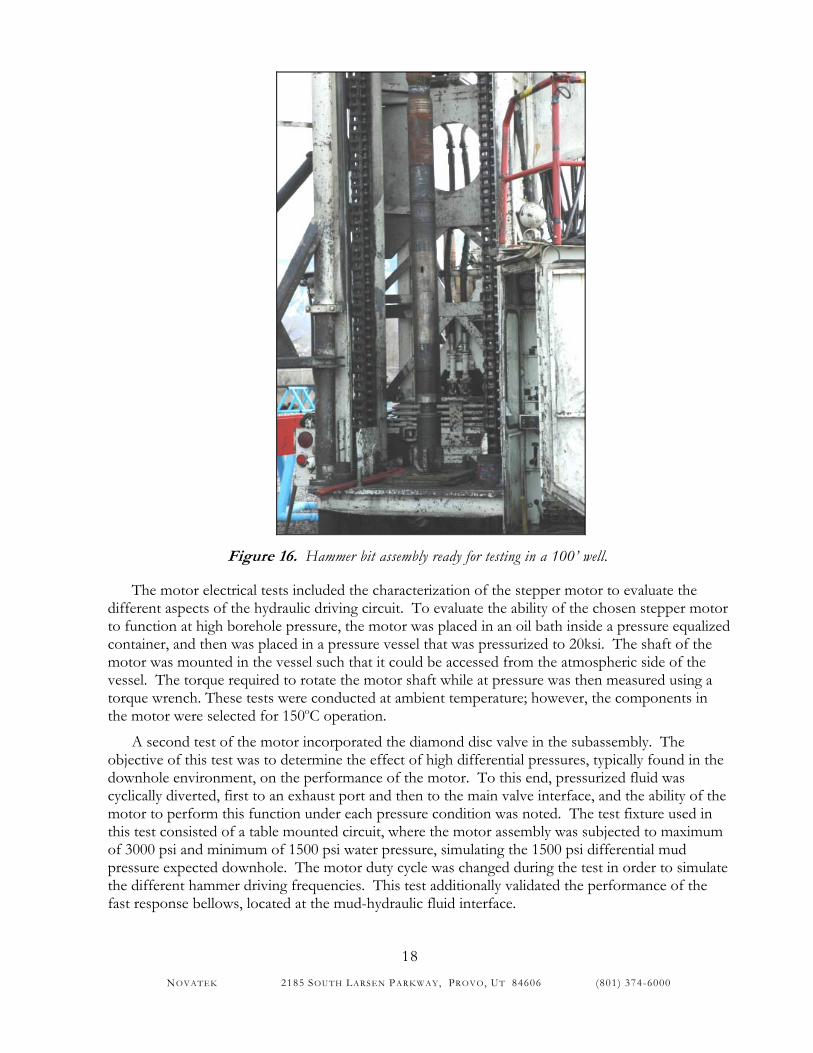
The final test of the entire bit assembly consisted of a 90’ rotary drilling test through high compressive strength concrete. The test was conducted in Novatek’s 100 ft well. The well was initially completely filled with concrete, and allowed to set for one week. The starting concrete level was measured at the start of the test to ensure a minimum of 90’ was drilled. A water based mud (bentonite and barite) was mixed to a density of 10ppg at the start of the drill test. The BHA, shown in Figure 16, consisted of a collar and a top sub adapting the uppermost connection of the hammer BHA to the connection on the rig. No impact was produced by the tool during the test; however, a series of Belleville springs were included in the area between the piston assembly and the bit to provide non-linear recoil to the bit during the drill test. The drill test plan included measurement of ROP in 10’ increments in order to identify any operational or performance problems as they arose (such as cutters and nozzle clogging or failure of any bit components). A Gardner Denver pump used for the test was set to pressure differential of approximately 1500 psi, the maximum expected operating pressure of the hammer system.
Valve Assembly Testing Program. Valve assembly tests were conducted to determine the performance of various critical components in the valve, when subjected to extreme environmental conditions normally found in downhole wells. The conditions of most concern in the testing were high ambient and differential pressure. The tests were devised to validate mechanical and electrical function, and included tests of the performance of the valve plates and related driving hydraulic circuit, and the characterization of the motor driving the hydraulic circuit.
NOVATEK 2185 SOUTH LARSEN PAR KWAY, PROVO, UT 84606 (801) 374-6000
18
Figure 16. Hammer bit assembly ready for testing in a 100’ well.
The motor electrical tests included the characterization of the stepper motor to evaluate the different aspects of the hydraulic driving circuit. To evaluate the ability of the chosen stepper motor to function at high borehole pressure, the motor was placed in an oil bath inside a pressure equalized container, and then was placed in a pressure vessel that was pressurized to 20ksi. The shaft of the motor was mounted in the vessel such that it could be accessed from the atmospheric side of the vessel. The torque required to rotate the motor shaft while at pressure was then measured using a torque wrench. These tests were conducted at ambient temperature; however, the components in the motor were selected for 150oC operation.
A second test of the motor incorporated the diamond disc valve in the subassembly. The objective of this test was to determine the effect of high differential pressures, typically found in the downhole environment, on the performance of the motor. To this end, pressurized fluid was cyclically diverted, first to an exhaust port and then to the main valve interface, and the ability of the motor to perform this function under each pressure condition was noted. The test fixture used in this test consisted of a table mounted circuit, where the motor assembly was subjected to maximum of 3000 psi and minimum of 1500 psi water pressure, simulating the 1500 psi differential mud pressure expected downhole. The motor duty cycle was changed during the test in order to simulate the different hammer driving frequencies. This test additionally validated the performance of the fast response bellows, located at the mud-hydraulic fluid interface.
NOVATEK 2185 SOUTH LARSEN PAR KWAY, PROVO, UT 84606 (801) 374-6000
19
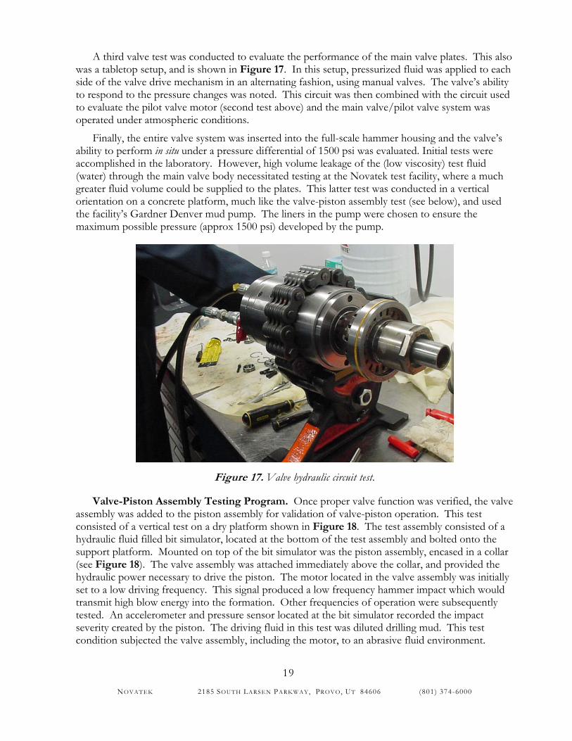
A third valve test was conducted to evaluate the performance of the main valve plates. This also was a tabletop setup, and is shown in Figure 17. In this setup, pressurized fluid was applied to each side of the valve drive mechanism in an alternating fashion, using manual valves. The valve’s ability to respond to the pressure changes was noted. This circuit was then combined with the circuit used to evaluate the pilot valve motor (second test above) and the main valve/pilot valve system was operated under atmospheric conditions.
Finally, the entire valve system was inserted into the full-scale hammer housing and the valve’s ability to perform in situ under a pressure differential of 1500 psi was evaluated. Initial tests were accomplished in the laboratory. However, high volume leakage of the (low viscosity) test fluid (water) through the main valve body necessitated testing at the Novatek test facility, where a much greater fluid volume could be supplied to the plates. This latter test was conducted in a vertical orientation on a concrete platform, much like the valve-piston assembly test (see below), and used the facility’s Gardner Denver mud pump. The liners in the pump were chosen to ensure the maximum possible pressure (approx 1500 psi) developed by the pump.
Figure 17. Valve hydraulic circuit test.
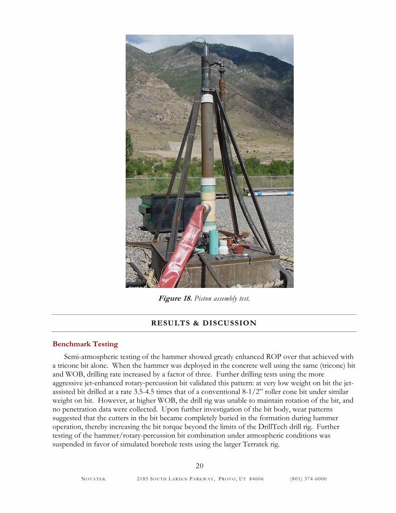
Valve-Piston Assembly Testing Program. Once proper valve function was verified, the valve assembly was added to the piston assembly for validation of valve-piston operation. This test consisted of a vertical test on a dry platform shown in Figure 18. The test assembly consisted of a hydraulic fluid filled bit simulator, located at the bottom of the test assembly and bolted onto the support platform. Mounted on top of the bit simulator was the piston assembly, encased in a collar (see Figure 18). The valve assembly was attached immediately above the collar, and provided the hydraulic power necessary to drive the piston. The motor located in the valve assembly was initially set to a low driving frequency. This signal produced a low frequency hammer impact which would transmit high blow energy into the formation. Other frequencies of operation were subsequently tested. An accelerometer and pressure sensor located at the bit simulator recorded the impact severity created by the piston. The driving fluid in this test was diluted drilling mud. This test condition subjected the valve assembly, including the motor, to an abrasive fluid environment.
NOVATEK 2185 SOUTH LARSEN PAR KWAY, PROVO, UT 84606 (801) 374-6000
20
Figure 18. Piston assembly test.
RESULTS & DISCUSSION
Benchmark Testing
Semi-atmospheric testing of the hammer showed greatly enhanced ROP over that achieved with a tricone bit alone. When the hammer was deployed in the concrete well using the same (tricone) bit and WOB, drilling rate increased by a factor of three. Further drilling tests using the more aggressive jet-enhanced rotary-percussion bit validated this pattern: at very low weight on bit the jet-assisted bit drilled at a rate 3.5-4.5 times that of a conventional 8-1/2” roller cone bit under similar weight on bit. However, at higher WOB, the drill rig was unable to maintain rotation of the bit, and no penetration data were collected. Upon further investigation of the bit body, wear patterns suggested that the cutters in the bit became completely buried in the formation during hammer operation, thereby increasing the bit torque beyond the limits of the DrillTech drill rig. Further testing of the hammer/rotary-percussion bit combination under atmospheric conditions was suspended in favor of simulated borehole tests using the larger Terratek rig.
NOVATEK 2185 SOUTH LARSEN PAR KWAY, PROVO, UT 84606 (801) 374-6000
21
Testing under simulated borehole conditions yielded very promising results in terms of potential for large ROP increases; however, other weaknesses of the hammer were also uncovered. The following is a summary of the lessons learned from the benchmark testing.
Hammer robustness (Revision 4). Both the pseudo-atmospheric and simulated borehole tests have shown that the version of the Novatek hammer tested in the Terratek tests can start and operate faithfully under a variety of conditions. However, in optimizing the operation of the hammer for maximum output power, it was found that factors such as mud weight and/or viscosity must be considered. For example, just prior to simulated borehole tests at Terratek, the stroke of the Novatek hammer was optimized in atmospheric tests using water as the operating fluid. However, in Terratek’s 15 lb/gal mud, operation of the hammer was erratic until the hammer stroke was lengthened slightly. This difference in operation was due to increased frictional drag on the hammer valve, which controls timing of the hammer cycle. In its limit, where frictional drag on the valve is excessive, the hammer is unable to sustain operation. This latter condition was achieved, also during the Terratek testing, when the hammer was left with mud inside it for a week. Dried mud packed in one valve chamber prevented proper reciprocation of the valve and caused a condition where hammer reciprocation was unsustainable.
Another robustness issue arose in the course of optimizing hammer cycle efficiency. Impact between the valve and its lower stop has been found to generally increase as the timing of the hammer cycle is optimized to give maximum hammer output power. Thus, as hammer power is increased, failure rate of valve and lower stop is also increased. All of these key robustness issues are linked with the shuttling valve design used in the testing, which must be improved prior to extended field use of the hammer.
In addition to valve failure by impact, erosion and abrasive wear are also robustness issues that are significant. Extended testing of the tool has previously been conducted using a variety of drilling fluids, including water, bentonite gel, and weighted drilling mud (10-14 lb/gal). This testing has uncovered certain high wear regions of the valve, which is the component that sees the highest stresses, sliding velocities, and erosion potential. Implementation of various design solutions for addressing this wear during the course of the project has significantly improved the ease and reliability of starting the tool. Reliability has been demonstrated through hundreds of start-stop cycles. Most of the components in the various prototype tools (through revision 4) have seen over 50 hours of operating time without failure. The life of the diamond coated valve in revision 5 is expected to greatly improve service longevity of the overall tool. Further testing for extended periods is still needed, with the goal of continuously improving service life.
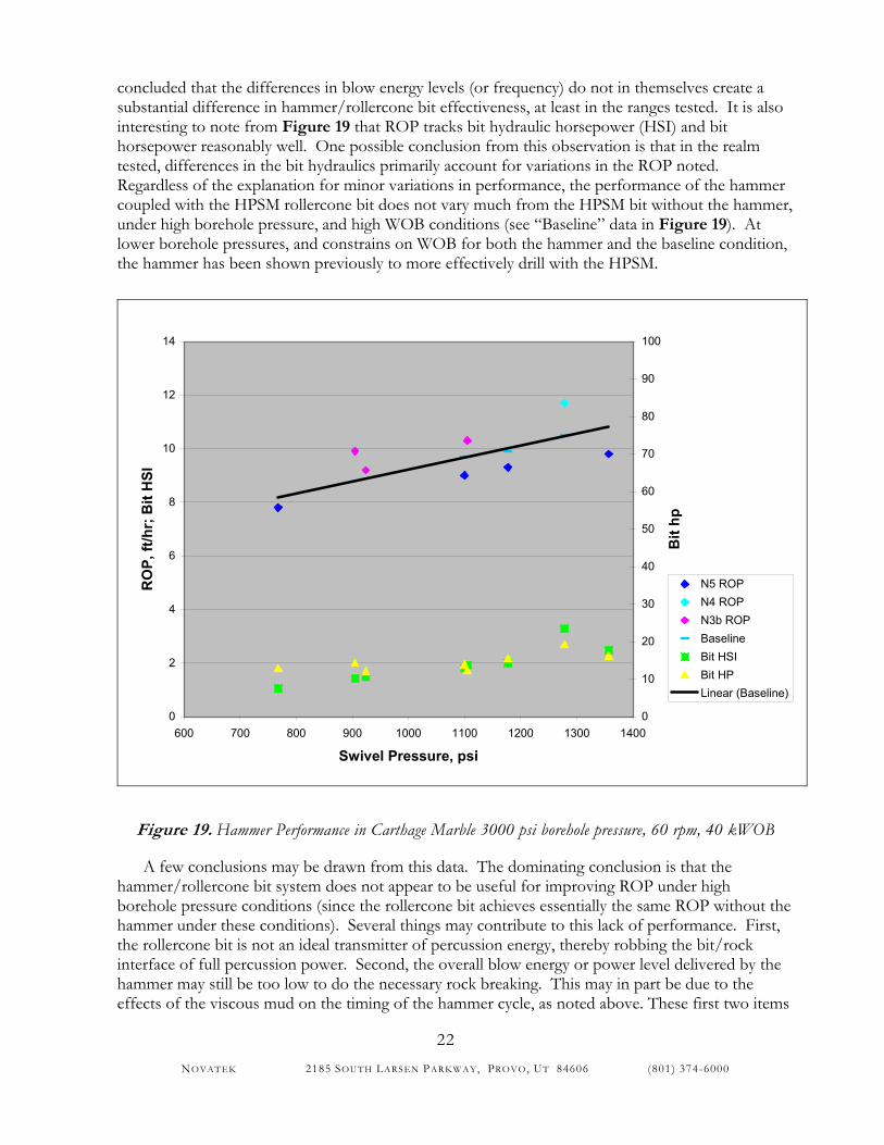
Hammer effectiveness when used with rollercone bit under simulated borehole conditions. Figure 19 shows the penetration rate of an 8-1/2” Reed HPSM rollercone bit assisted by the hammer in Carthage Marble, using a 10 lb mud. All data points were obtained at a rotational speed of 60 rpm and 40,000 lb weight on bit (WOB). Also plotted on the graph are the results of testing of previous versions of the hammer under the same borehole conditions. As shown, all rate of penetration (ROP) points generally fall on the same linear curve that generally increases with hammer pressure drop (swivel pressure).
Particularly interesting is the fact that the data taken from hammer revision N3b lies within the same range of data as does the data from revisions N4 and N5. Revision N3b is fundamentally different from revisions N4 and N5: N3b was designed for a higher nominal stroke rate and a low mass piston, whereas the latter versions were designed for a lower nominal stroke rate and a high mass piston, with correspondingly higher blow energy. From the similarity of the data, it may be
NOVATEK 2185 SOUTH LARSEN PAR KWAY, PROVO, UT 84606 (801) 374-6000
22
concluded that the differences in blow energy levels (or frequency) do not in themselves create a substantial difference in hammer/rollercone bit effectiveness, at least in the ranges tested. It is also interesting to note from Figure 19 that ROP tracks bit hydraulic horsepower (HSI) and bit horsepower reasonably well. One possible conclusion from this observation is that in the realm tested, differences in the bit hydraulics primarily account for variations in the ROP noted. Regardless of the explanation for minor variations in performance, the performance of the hammer coupled with the HPSM rollercone bit does not vary much from the HPSM bit without the hammer, under high borehole pressure, and high WOB conditions (see “Baseline” data in Figure 19). At lower borehole pressures, and constrains on WOB for both the hammer and the baseline condition, the hammer has been shown previously to more effectively drill with the HPSM.
0
2
4
6
8
10
12
14
600 700 800 900 1000 1100 1200 1300 1400
Swivel Pressure, psi
RO
P, ft
/hr;
Bit
HSI
0
10
20
30
40
50
60
70
80
90
100
Bit
hp
N5 ROPN4 ROPN3b ROPBaselineBit HSIBit HPLinear (Baseline)
Figure 19. Hammer Performance in Carthage Marble 3000 psi borehole pressure, 60 rpm, 40 kWOB
A few conclusions may be drawn from this data. The dominating conclusion is that the hammer/rollercone bit system does not appear to be useful for improving ROP under high borehole pressure conditions (since the rollercone bit achieves essentially the same ROP without the hammer under these conditions). Several things may contribute to this lack of performance. First, the rollercone bit is not an ideal transmitter of percussion energy, thereby robbing the bit/rock interface of full percussion power. Second, the overall blow energy or power level delivered by the hammer may still be too low to do the necessary rock breaking. This may in part be due to the effects of the viscous mud on the timing of the hammer cycle, as noted above. These first two items
NOVATEK 2185 SOUTH LARSEN PAR KWAY, PROVO, UT 84606 (801) 374-6000
23
would lead the development effort into seeking still higher energy realms of hammer operation. Percussive drilling has long been understood as a threshold phenomenon: below a certain energy threshold, percussive energy is not particularly effective in breaking rock. Hence, due to energy attenuation by the bit and loss of efficiency by viscous damping, the energy provided by the hammer in these tests may simply be below threshold.
However, observations that borehole pressure provides a dominating effect on hammer performance9 suggest that the percussion drilling mode alone is not effective where high chip hold down is present. In high borehole pressure applications, drilling enhancements aimed at countering chip hold down may prove beneficial. Included in this group of enhancements are high-pressure jets and rotary-percussive cutters. Further test data using a jet-assisted fixed cutter bit can be used to support this latter point. In these tests, a moderately-powered Novatek system achieved dramatically higher ROP under certain conditions than did a higher energy conventional hammer. Hence, hammer drilling at depth may respond to some “finesse” as well as a “brute force” threshold. Further discussion of this concept is given below.
Prototype bit robustness. Initial runs of the jet-assisted rotary percussion bit under simulated borehole conditions were hampered by difficulties with the distributed high-pressure nozzles, including blown nozzles, plugged nozzles, and washed/cracked high pressure passageways. Plugging of high-pressure nozzles typically followed the loss of jet pressure in a few of the bit blades due to the other problems just mentioned. Hence, initial tests were not considered to be adequate representations of the capabilities of the bit. After repair of the bit, final tests were run without bit failure. The final condition of the bit was such that most jet nozzles were fully operational, suggesting that the latter tests in the test sequence (i.e. tests 11 and 12 in Table 1) were more indicative of desired high pressure jet operation. In addition, following all tests, all of the high impact polycrystalline diamond cutters were in “green” condition, free from damage and wear. However, the condition of the steel bit body was not such that it could be expected to reliably run a regimen of further tests. This calls for further improvement in the design and manufacture of the bit body.
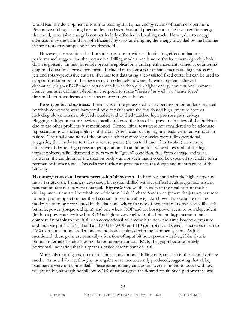
Hammer/jet-assisted rotary percussion bit system. In hard rock and with the higher capacity rig at Terratek, the hammer/jet-assisted bit system drilled without difficulty, although inconsistent penetration rate results were obtained. Figure 20 shows the results of the final tests of the bit drilling under simulated borehole conditions in Crab Orchard Sandstone (where the jets are assumed to be in proper operation per the discussion in section above). As shown, two separate drilling modes seem to be represented by the data: one where the rate of penetration increases steadily with bit horsepower (torque and rpm), and one where ROP and bit horsepower seem to be independent (bit horsepower is very low but ROP is high to very high). In the first mode, penetration rates compare favorably to the ROP of a conventional rollercone bit under the same borehole pressure and mud weight (15 lb/gal) and at 40,000 lb WOB and 110 rpm rotational speed – increases of up to 45% over conventional rollercone methods are achieved with the hammer system. As just mentioned, these gains are primarily a function of input bit horsepower – in fact, if the data is plotted in terms of inches per revolution rather than total ROP, the graph becomes nearly horizontal, indicating that bit rpm is a major determinant of ROP.
More substantial gains, up to four times conventional drilling rate, are seen in the second drilling mode. As noted above, though, these gains were inconsistently produced, suggesting that all key parameters were not controlled. These extraordinary data points were all noted to occur with low weight on bit, although not all low WOB situations gave the desired result. Such performance was
NOVATEK 2185 SOUTH LARSEN PAR KWAY, PROVO, UT 84606 (801) 374-6000
24
not observed with a rollercone bit (nor with the more conventional hammers tested in the test series using a mining style button bit), and it was not as pronounced when drilling in Carthage Marble.
0
5
10
15
20
25
30
35
40
0 5 10 15 20 25 30 35 40Bit horsepower, hp
RO
P, ft
/hr
Figure 20. Hammer/PHAST bit Performance in Crab Orchard Sandstone, 3000 psi borehole pressure
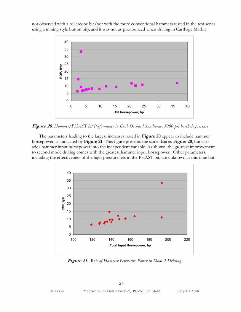
The parameters leading to the largest increases noted in Figure 20 appear to include hammer horsepower, as indicated by Figure 21. This figure presents the same data as Figure 20, but also adds hammer input horsepower into the independent variable. As shown, the greatest improvement to second mode drilling comes with the greatest hammer input horsepower. Other parameters, including the effectiveness of the high-pressure jets in the PHAST bit, are unknown at this time but
0
5
10
15
20
25
30
35
40
100 120 140 160 180 200 220Total Input Horsepower, hp
RO
P, fp
h
Figure 21. Role of Hammer Percussive Power in Mode 2 Drilling
NOVATEK 2185 SOUTH LARSEN PAR KWAY, PROVO, UT 84606 (801) 374-6000
25
are deemed worth pursuing. Inconsistent attainment of the most effective drilling results could be due to inconsistent jetting activity from the bit as well as lack of adequate control of WOB.
Lessons learned. From the testing just described, the following lessons were learned:
• Borehole pressure is a significant factor in hammer effectiveness in a mud-flushed drilling application.
• The hammer designs tested were too sensitive to changes in mud weight – optimum operation of the hammer is altered by moving through the range of water to 10 lb mud to 15 lb mud.
• Letting the tool stand for any period of time, which allows the drilling mud to dry, can foul the present hammer valve. This condition was experienced even though the tool was flushed with clear water. Modification of the valve can relieve this issue.
• Hammers with roller cone bits at present levels of impact do not provide increased penetration rates.
• Increased performance was noted at two distinct areas. One was at higher bit horsepower (rpm x WOB). The other was observed at lower bit horsepower and was unexpected. • The new unexpected drilling mode was observed in the transition of low WOB to
higher WOB. At these lower WOB levels, elevated penetration rates were observed in spite of lower horsepower being applied.
• The unexpected mode was observed at a variety of conditions and is believed to be real.
• This new drilling mode needs to be explored and better understood.
In response to the above lessons, the objectives governing further hammer development have become:
a) to improve the robustness and control of the hammer in typical borehole conditions and build a hammer and bit that is suitable for further optimization studies and field demonstration,
b) to determine the parameters that lead to consistently high penetration rate of the hammer/PHAST bit system, and
c) to demonstrate benefits of the hammer/PHAST bit system under typical borehole conditions and gain oil industry interest in further development and testing.
Prototype development and testing – revision 5
The above objectives and the design strategies chosen to accomplish these objectives have necessitated a substantial redesign of the hammer. Not only did the valve mechanism dramatically change, but the piston itself was literally turned inside out in an attempt to improve the robustness of the impact surface and reduce leakage flow and erosion potential across the linear bearing surfaces of the hammer. One key benefit arising from the redesign is a modularization of the hammer system. While this adds some complexity and degrees of freedom (which are not implicitly controlled) to the overall system, it also allows for simplified debugging of the individual subsystems, offers long term commercial benefits in terms of replacement and refurbishing the tool for optimized life, and offers enhanced ability to separate and investigate the influence of specific variables on overall tool performance. In the final design, the valve motion is independent of the
NOVATEK 2185 SOUTH LARSEN PAR KWAY, PROVO, UT 84606 (801) 374-6000
26
piston motion, except through electronic feedback loops. Hence, impact point, stroke, frequency, and blow energy are largely independently controllable variables.
Major upgrades were also applied to the jet-enhanced bit to implement new anti-whirl technology, improve bit body manufacturing and robustness, reduce the part count and increase the robustness of the pressure intensification mechanism within the bit, and prevent loss or clogging of high pressure jet nozzles. The latter objective was achieved by development of a new retention mechanism for the small nozzles, by providing redundant flow passages within the nozzles, and by enlarging the minimum flow diameter.
Testing of prototypes incorporating these design improvements has for the most part led stepwise to a working prototype system. However, difficulties attending the sweeping changes undertaken have slowed progress beyond projections, leaving much of the design optimization and validation work left to be done. The following is a summary of the accomplishments to date.
Bit Assembly Testing. Initial tests of the conduits containing electronic control lines within the bit showed that both conduits tested performed satisfactorily in the test; there was no pressure induced elongation or buckling observed in either conduit. Alloy 2205 was selected for high corrosion resistant applications, keeping 316L as the primary alternate material.
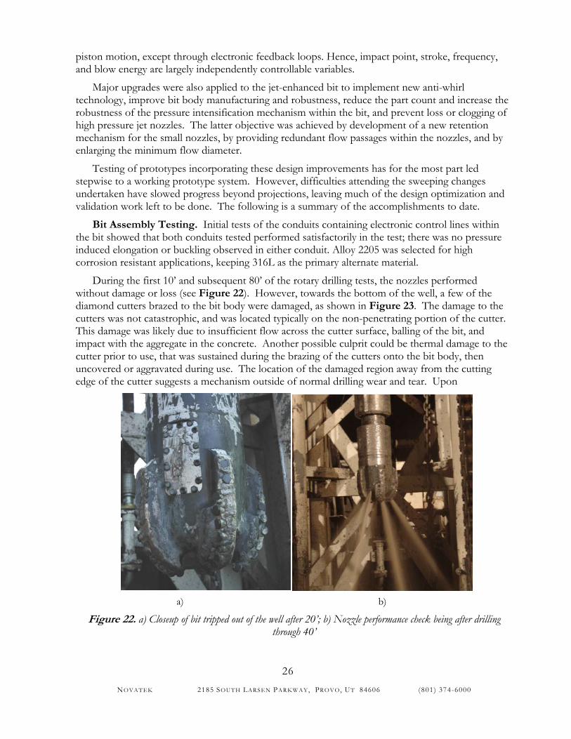
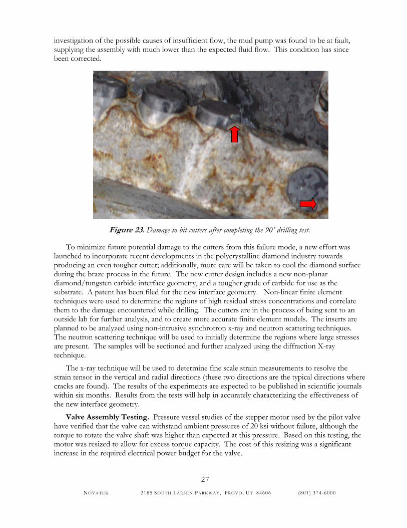
During the first 10’ and subsequent 80’ of the rotary drilling tests, the nozzles performed without damage or loss (see Figure 22). However, towards the bottom of the well, a few of the diamond cutters brazed to the bit body were damaged, as shown in Figure 23. The damage to the cutters was not catastrophic, and was located typically on the non-penetrating portion of the cutter. This damage was likely due to insufficient flow across the cutter surface, balling of the bit, and impact with the aggregate in the concrete. Another possible culprit could be thermal damage to the cutter prior to use, that was sustained during the brazing of the cutters onto the bit body, then uncovered or aggravated during use. The location of the damaged region away from the cutting edge of the cutter suggests a mechanism outside of normal drilling wear and tear. Upon
a) b)
Figure 22. a) Closeup of bit tripped out of the well after 20’; b) Nozzle performance check being after drilling through 40’
NOVATEK 2185 SOUTH LARSEN PAR KWAY, PROVO, UT 84606 (801) 374-6000
27
investigation of the possible causes of insufficient flow, the mud pump was found to be at fault, supplying the assembly with much lower than the expected fluid flow. This condition has since been corrected.
Figure 23. Damage to bit cutters after completing the 90’ drilling test.
To minimize future potential damage to the cutters from this failure mode, a new effort was launched to incorporate recent developments in the polycrystalline diamond industry towards producing an even tougher cutter; additionally, more care will be taken to cool the diamond surface during the braze process in the future. The new cutter design includes a new non-planar diamond/tungsten carbide interface geometry, and a tougher grade of carbide for use as the substrate. A patent has been filed for the new interface geometry. Non-linear finite element techniques were used to determine the regions of high residual stress concentrations and correlate them to the damage encountered while drilling. The cutters are in the process of being sent to an outside lab for further analysis, and to create more accurate finite element models. The inserts are planned to be analyzed using non-intrusive synchrotron x-ray and neutron scattering techniques. The neutron scattering technique will be used to initially determine the regions where large stresses are present. The samples will be sectioned and further analyzed using the diffraction X-ray technique.
The x-ray technique will be used to determine fine scale strain measurements to resolve the strain tensor in the vertical and radial directions (these two directions are the typical directions where cracks are found). The results of the experiments are expected to be published in scientific journals within six months. Results from the tests will help in accurately characterizing the effectiveness of the new interface geometry.
Valve Assembly Testing. Pressure vessel studies of the stepper motor used by the pilot valve have verified that the valve can withstand ambient pressures of 20 ksi without failure, although the torque to rotate the valve shaft was higher than expected at this pressure. Based on this testing, the motor was resized to allow for excess torque capacity. The cost of this resizing was a significant increase in the required electrical power budget for the valve.
NOVATEK 2185 SOUTH LARSEN PAR KWAY, PROVO, UT 84606 (801) 374-6000
28
Under differential pressures applied through the pilot valve, there was no discernible change in the rotation speed of the motor at these high differential pressures.
Considerable difficulty was encountered once the valve assembly was tested as a complete unit inside its full-scale housing. First of all, the leakage through the main valve plates was excessive, preventing building of any substantial motive pressure in the fluid. Secondly, a force imbalance (at high differential pressure) was uncovered within the system, which greatly increased the torque required to rotate the valve plates. The result of these factors was the inability of the valve plates to move through the full range of motion. The solution was first to force-balance the plates, and second to create a very large fluid volume that would drive the plates, and overcoming the leakage pressure losses by providing a high flow rate. Once force balanced, test results indicated that a very low actuation pressure of about 100 psi could actuate the diamond plates. Once a sustainable fluid pressure source (the large mud pumps at the Novatek test facility) was connected to the valve assembly, the valve rotated through its full range of motion. Even so, the frequency of the valve was not identical to the motor input signal, suggesting some hydraulic locking was occurring at certain frequencies. The issue was addressed with increased gap between the main plate valve members, which results in a loss of flow efficiency.
This test program has underscored the reliance of the present design of the valve on precise balance of the forces acting on the valve plates. Without this balance, rotational force requirements may exceed those available from the valve driver design. At present, force balance is accomplished by use of thrust bearings and hydraulic pressure balancing of various components. Such bearings reduce the overall dynamic response of the valve system and require precise assembly tolerances. Further work is therefore recommended to design a more inherently balanced system that does not rely on the thrust bearings.
Valve-Piston Assembly Testing. Upon assembly of the entire debugged system (less bit), overall operation of the hammer was verified at flow rates up to 420 gpm and pressures up to 775 psi. Higher flow rates were not possible with the liners used in the pump setup. The piston actuated successfully over a range of frequencies – the hammering frequency was varied by the pilot valve motor from 0.25 Hz to 28.5 Hz. Impact of the hammer was audible. The piston was able to be controlled instantaneously by modifying the input signal sent to the valve assembly. The test proved the viability of an electromechanical system to drive a hammer piston.
REMAINING TECHNICAL HURDLES
Several remaining technical hurdles were identified during the experimental phase of the program. The primary of these include:
1. Manufacturing of valve plates – processes for creating the diamond enhanced valve plates are still in their infancy and are problematic at present. Further development of attachment processes (e.g. brazing) and tooling is needed, along with cost effective methods for finishing the assembled valve plates, such that flatness tolerances are maintained.
2. Powering of the valve motor – present motor power draw is large enough to require down-hole power generation. The hammer must therefore be married to a power generator prior to field deployment. Alternatively, steps may be taken to reduce overall
NOVATEK 2185 SOUTH LARSEN PAR KWAY, PROVO, UT 84606 (801) 374-6000
29
system losses (friction) and increase system efficiency so that use of battery power becomes feasible.
3. System tuning and optimization – the successful test of the prototype hammer must be followed by tuning of output parameters for optimized drilling. This suggests the need for extensive testing in the laboratory, in borehole simulators, and in the field. As mentioned above, with the flexibility that is designed into the present system comes the need to understand and control several more variables than were controlled in previous hammer revisions.
4. Improvement of main valve design – the present design of the main valve plates is effective, but not robust, since it is quite sensitive to assembly tolerance, wear, and downhole conditions. Further development work is needed to design an inherently balanced valve to improve valve efficiency, reduce valve inertia, reduce valve wear, and minimize the hydraulic locking found at some valve actuation frequencies.
5. Sensor development – feedback sensors have been designed, but have not yet been implemented into the prototype hammer. In addition, means of transmitting information from sensors in the hammer and (later) in the bit to the control module must be developed and implemented.*
COMMERCIALIZATION
Commercial Potential
The commercial potential of a Novatek hammer as a drilling rate enhancement has been analyzed previously.10 This analysis concluded that the hammer could be economically competitive with approximately 50% increase in penetration of soft rocks, depending on rig costs. This conclusion assumed a mean time between repairs of 120 hours and a useful life of 6 repair cycles; however, no benefits were added into the equation for improvements in bit life (which would reduce either the required life or the required penetration rate improvements). The Novatek hammer has already demonstrated its ability to offer improvements to penetration rate on this order, under certain conditions. What remains to be seen is how much greater improvement in penetration rate is offered by the most recent operational changes, and how long the hammer can operate at these energy levels before repairs are needed.
A significant potential exists for the hammer to not only provide economically beneficial penetration rate improvements, but to also provide for look ahead measurements while drilling, and * It is worth noting that a rotary hydraulic connector has been designed to route sensor wires from the bit assembly to a data acquisition and transmission system located in the valve assembly. Most connectors already available in the oil and gas industry are bulky and not fully metal-to-metal sealed. As a result, a new connector, which enabled connections to be made small confined spaces in the internal part of the hammer, was developed. The connector consists of a two-jam nut assembly with a ferrule seal stack anchoring the primary jam nut onto the umbilical. Spring energized metal-to-metal seals acted ad redundant sealing elements. Since it is a unique design, a patent has been applied for. The redundant metal-to-metal seals ensure that the sensor conductors which the connector protects from the drilling environment are as robust as possible.
NOVATEK 2185 SOUTH LARSEN PAR KWAY, PROVO, UT 84606 (801) 374-6000
30
controlled bit deviation. These latter benefits are seen as bringing economic benefits through more effective drilling, and are also enabling technologies for future smart drilling systems.
Commercial applications of the technology
Penetration improvements. The mud actuated hammer has primary application in hard rock regions, in hard/soft interbedded formations, and in crooked hole applications, where drilling rate may be increased most dramatically by percussion. Deep wells where high borehole pressures are encountered show suboptimal drilling rates due to increased chip holddown, filter cake, etc. The jet-assisted bit is expected to improve drilling in such wells by more effectively removing filter cake and providing ingress of pressurized fluid into formation cracks, reducing chip holddown.
Rotary-steerable drilling. In connection with the jet-assisted bit, the hammer is expected to have application in a much broader selection of formations than those just mentioned, once an ability to steer the bit and improve drilling efficiency is fully developed. Since the jet-enhanced steering system does not rely on conventional sliding-mode deviation practice (it is a true “rotary-steerable” system), inefficiencies in directional drilling due to sliding-mode are eliminated. Furthermore, since the primary mode of drilling utilized by this system (jet-assisted hammer drilling) is faster than conventional means, this system offers potential cost savings over other rotary-steerable systems that rely on conventional drilling means.
Look ahead. With proper down-hole and surface monitoring equipment, the hammer and its attendant hydraulic pressure fluctuations and drill bit noise can be used as a multi-frequency noise emitter. The overall design of the hammer allows for drilling with or without operation of the hammer. Hence, the noise source may be turned off and on as needed for proper formation evaluation. Potential benefits from these features include more accurate real-time tracking of the wellbore trajectory, estimation of formation porosity, pore pressure, and lithology, simplification of casing programs, and the ability to look ahead of the bit and identify forthcoming formation anomalies or problem zones.
Commercialization Plans
Plans to commercialize the hammer and its attendant advanced drilling system technologies are dependant upon further technical progress of the hammer itself. At present Novatek is pursuing other development projects that are expected to be fruitful in the shorter term than expected for the hammer developments outlined above. Success with the hammer system will require further R&D work and significant funding participation by oilfield services and operating companies.
CONCLUSIONS & RECOMMENDATIONS
Based on the above data and discussion, the following conclusions may be drawn:
1) A down-hole mud actuated hammer can yield substantial improvements to drilling rate in overbalanced, hard rock formations. Improvements are dependent on bit design, weight on bit, and hammer horsepower at least.
NOVATEK 2185 SOUTH LARSEN PAR KWAY, PROVO, UT 84606 (801) 374-6000
31
2) A down-hole mud actuated hammer can serve to provide other useful down-hole functions including generation of high pressure mud jets, generation of seismic and sonic signals, and generation of diagnostic information based on hammer velocity profiles.
3) Neither a mud hammer-driven rotation system nor a hammer-based acoustic communications system is a beneficial use of available hammer horsepower.
To continue improvement, ensure commercial success of the hammer system, and ensure that long-term goals of improvements to the drilling process are realized, the technical hurdles listed above must be addressed. Once these issues are solved, extensive field testing and demonstration is required to: first, demonstrate the utility of the system; second, fine tune the drilling parameters; and third, learn what is needed to further field-harden components and to improve the utility of the system, determine component life (mean time between failures) and develop maintenance schedules.
ACKNOWLEDGEMENT
The substantial contribution of the DOE to this development project, as well as its overall contribution in the field of mud hammer development, has been greatly appreciated by the authors and all those associated with the project. DOE vision, funding, and personal efforts have contributed to substantial progress toward this elusive dream for improved hard rock drilling performance and “smart” drilling.
REFERENCES
1 Santi, P., Bell, S., and Summers, D.A., Univ. of MO-Rolla; Pixton, D., Novatek, “Waterjet Assisted Polycrystalline Diamond Indentation Drilling of Rock," in Proceedings 14th Inter-national Conference on Jetting Technology, Brugge, Belgium, September 21-23, 1998. 2 Li, X., P. Santi, D. Summers, D. Pixton, “Laboratory Investigation into Application of PDC Cutters in Hard Rock Drilling Using Single Cutter Tests,” unpublished paper (2000). 3 Pixton, D.S. and D.R. Hall, “A Hammer-based Drilling System,” in Proceedings, Geothermal Resources Council Annual Meeting, Berkeley (September 25-27, 2000).
4 Bodare, A., “Non destructive test methods of stone and rock,” http://www.geoforum.com/knowledge/texts/bodare/, Chapter 2.3.1 Rebound methods, Schmidt hammer, Webforum Europe AB, 1998-2005.
5 Hand, M., C. Rueter, B.J. Evans, K. Dodds, T. Addis, “Look-Ahead Prediction of Pore Pressure While Drilling: Assessment of Existing and Promising Technologies,” Document GRI-99/0042, Gas Research Institute, Chicago, IL (February 1999). 6 Study performed by the Geotechnology Research Institute of the Houston Advanced Research Center, original period of study 1 July 1996 to 30 June 1998. 7 Pixton, D. and D.R. Hall, “A Rotary Percussive Drilling Engine,” in Proceedings of the 1998 ASME Energy Sources Technology Conference, Houston (February 2-4, 1998).
8 Pixton, D. and D. Hall, “Advanced Mud Hammer Systems,” in Proceedings of the 1999 Oil & Gas Conference, Dallas (June 28-30, 1999)
9 Tibbitts, G.A., R.C. Long, B.E. Miller, A. Judzis, A. Black, “World’s First Benchmarking of Drilling Mud Hammer Performance at Depth Conditions,” IADC/SPE 74540 (February, 2002).
NOVATEK 2185 SOUTH LARSEN PAR KWAY, PROVO, UT 84606 (801) 374-6000
32
10 Pierce, K., J. Finger, and B. Livesay, “Advanced Drilling Systems Study,” Technical Report SAND95-0331, Sandia National Laboratories, Albuquerque, NM (May 1996).