Embed Size (px)
Citation preview
INTEGRATED DISPLAY SYSTEMS
Lift-Net Installation Manual May 2004
integrated display systems
1555 W. Sherman Avenue, #170
Evanston, IL 60201
Technical Support Voice: (847) 475-2476
Fax: (847) 475-2535
Email: [email protected]
Internet: http://www.lift-net.com
ii
Table Of Contents Table Of Contents ...............................................................................................ii
Getting Started....................................................................................................1
Wiring Considerations........................................................................................2
Lift-Net Network Types.......................................................................................3
Lift-Net RS-422 Network Overview....................................................................3 Lift-Net RS-485 Network Overview....................................................................4 Lift-Net / LAN Overall View................................................................................5
Serial Links to Lift-Net........................................................................................7
CEC-SWIFT Futura ...........................................................................................7 SWIFT 5000 ......................................................................................................9 Elevator Controls Corp. ...................................................................................10 Motion Control Eng..........................................................................................12 Northern Interface ...........................................................................................17 O' Thompson...................................................................................................19 Kone Interface.................................................................................................21 Otis_Interface..................................................................................................25 Schindler .........................................................................................................28 ThyssenKrupp .................................................................................................30
Lift-Net IO Hardware .........................................................................................31
Hardwired Connections ...................................................................................31 Lift-Net - LN-LINK Interface.............................................................................33 Lift-Net Processor Card...................................................................................34 IO_48 Combo Board .......................................................................................35 IO96 Input Card...............................................................................................37 Relay Output Module.......................................................................................38
Lift-Net Peripheals ............................................................................................40
Battery Backup................................................................................................40 De-Sensitizing Modules...................................................................................41 Ethernet Serial Server .....................................................................................42 Mechanic On-Site Switch ................................................................................44 HV Module ......................................................................................................46 LN 485.............................................................................................................47 RS-485 / 232 Interface ....................................................................................47 LN 485 Isolated Repeater ...............................................................................49
Computer Setup................................................................................................50
This Computer Setup ......................................................................................50 Integrated Display ...........................................................................................55
Troubleshooting................................................................................................58

iii
Tech Support...................................................................................................58 Show Inputs Screen ........................................................................................65 Monitored Inputs..............................................................................................68
Contact Info.......................................................................................................69
Index ..................................................................................................................71


- 1 -
Getting Started Updated: 7/24/2004 10:57 PM
Verify that all the hardware/software required for your particular job is available.
Lift-Net hardware installations should contain I/O panels, I/O connection sheets, network interface, network wiring diagrams.
Serial linked installations will contain elevator controller to Lift-Net hardware interface connections, network interface, network wiring diagrams. Some installations require interface hardware supplied by the OEM.
All serial linked Lift-Net installations require that the controller have Lift-Net compatible software, available from the OEM.
Lift-Net Monitoring computers will be pre-loaded with Lift-Net software and configured per job spec.
When using customer PC’s a Lift-net install disk and printed instructions will be provided.
The above examples are for illustration purpose, refer to shipping receipt for job particulars.
Lift-Net I/O Hardware Panels
Consider how the I/O panels will be wired to the elevator system when determining their location.
I/O panel wiring 18 – 20 gauge stranded recommended.
Lift-Net I/O panels require a 120VAC @ 15amp power source. (dedicated circuit recommended)
Lift-Net Monitoring PC’s
Do not locate Monitoring PC’s near hoist motors, MG sets, transformers, or any high EMF source.
Lift-Net Monitoring PC’s require a 120VAC @ 15amp power source. (dedicated circuit recommended)
Monitoring PC’s that will be using LAN connections, must have the appropriate connection at the PC location. IP address and jack activation to be assigned by local IT Dept.

2
Wiring Considerations Updated: 7/24/2004 10:57 PM
Network Grounding, Shields and Splices
A continuous ground wire should be run from the Lift-Net M/R scanner to the LN485 or LN422 converter at the Lift-net computer.
Shielding must be continuous and grounded at the M/R Scanner only. All splices or termination’s in the line must have the shield spliced also, and grounded at the M/R Scanner.
To prevent noise and data loss all splices should be twisted together "Western Union" style over 2" - 3" and soldered
To prevent noise and data loss Lift-Net network wires must not be run in the same raceway with high voltage wiring.
Multiple M/R Scanners
When there is more than one M/R Scanner on the Lift-Net network the continuous ground wire should be grounded at every M/R Scanner on the network, and at the LN485 or LN422 converter at the Lift-net computer..
When there is more than one M/R Scanner on the Lift-Net network the continuous shield should be grounded at every M/R Scanner on the network. (see network layout)
IO Card Wiring
When wiring to 9-pin IO plugs leave 3-4 inches of slack to allow plugs to be repositioned should a configuration change be necessary.
18 – 20 gauge stranded wire recommended.
Network Wiring
To insure the best possible data quality we require that all network wiring be high quality shielded twisted pair. Such as the following available from Newark Electronics.
Manufacturer - CDT (Cable Design Technologies)
Manufacturer's type # - M54783-1000-GRY (Grey non plenum rated 1000' spool)
Newark Stock # - 91F9290
Manufacturer's type # - M55082-1000-GRY (Grey plenum rated 1000' spool)
Newark Stock # - 91F9294

- 3 -
Lift-Net Network Types
Lift-Net RS-422 Network Overview
Several controller manufacturers require an RS-422 network to interface the elevator controller with Lift-Net. This type of network must use home runs from each elevator or group of elevators to the monitoring PC. In addition each elevator or group must have a discrete serial communications port at the monitoring PC.
To insure the best possible data quality we require that all wiring from be high quality shielded twisted pair. Such as the following available from Newark Electronics.
Manufacturer - CDT (Cable Design Technologies)
Manufacturer's type # - M54783-1000-GRY (Grey non plenum rated 1000' spool)
Newark Stock # - 91F9290
Manufacturer's type # - M55082-1000-GRY (Grey plenum rated 1000' spool)
Newark Stock # - 91F9294
4
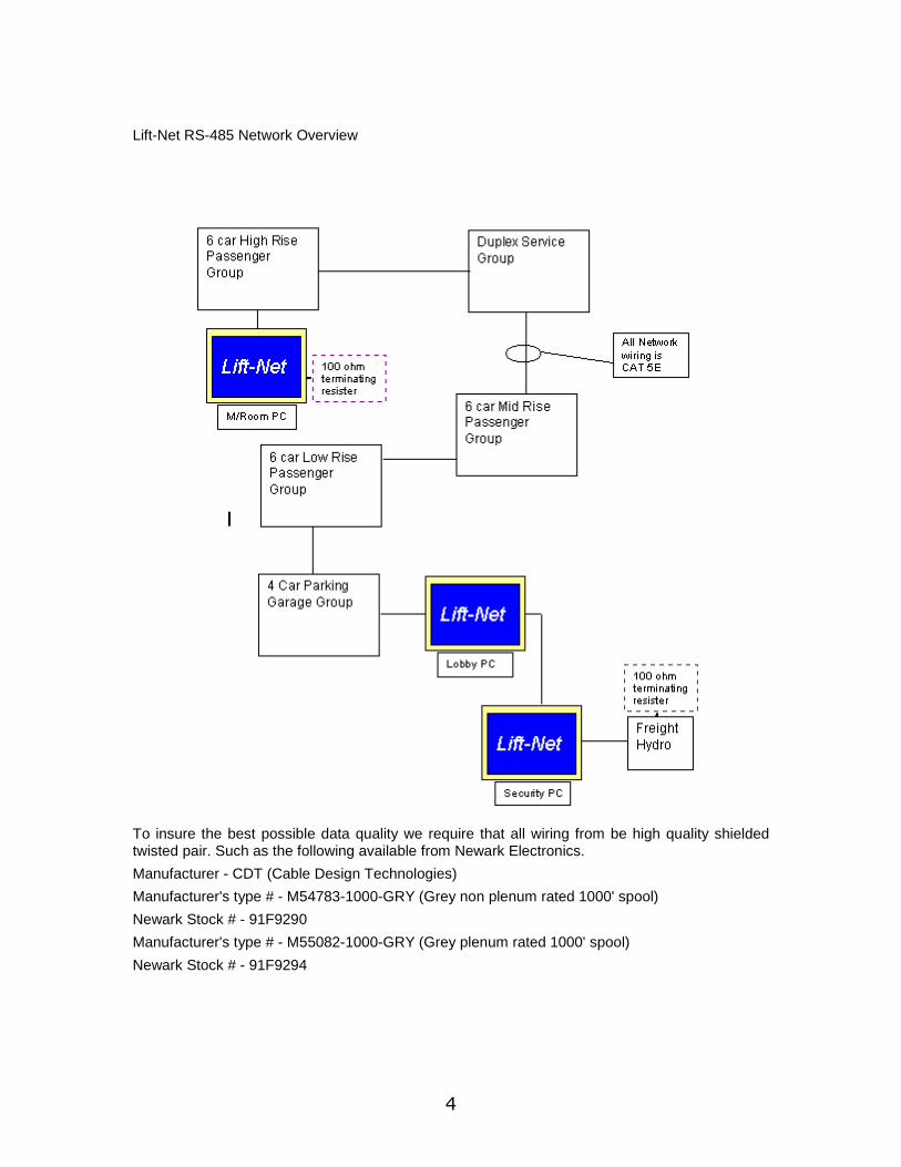
Lift-Net RS-485 Network Overview
To insure the best possible data quality we require that all wiring from be high quality shielded twisted pair. Such as the following available from Newark Electronics. Manufacturer - CDT (Cable Design Technologies) Manufacturer's type # - M54783-1000-GRY (Grey non plenum rated 1000' spool) Newark Stock # - 91F9290 Manufacturer's type # - M55082-1000-GRY (Grey plenum rated 1000' spool) Newark Stock # - 91F9294
- 5 -
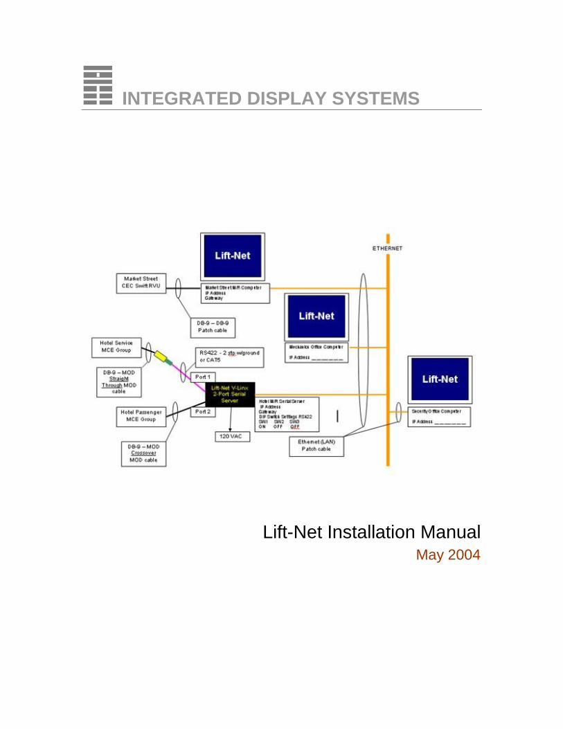
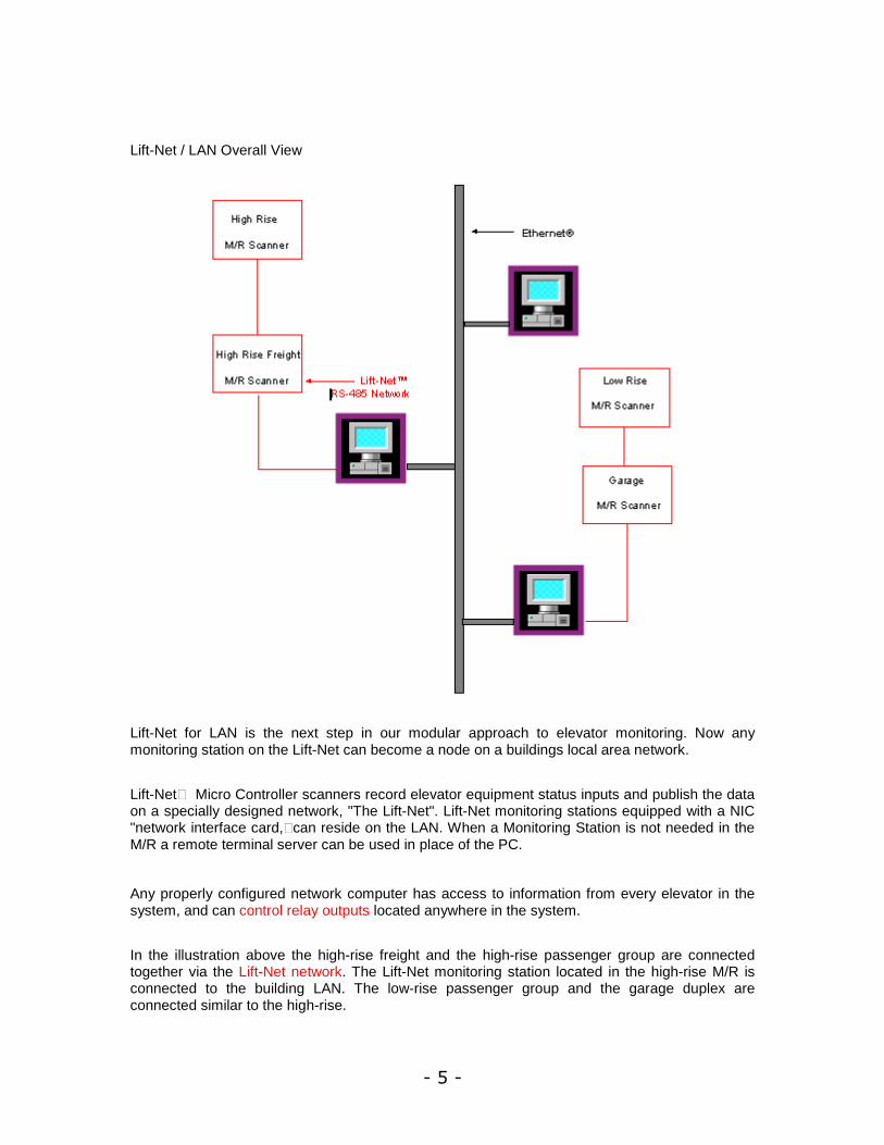
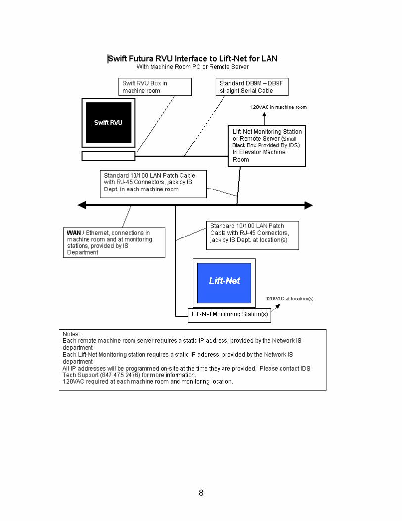
Lift-Net / LAN Overall View
Lift-Net for LAN is the next step in our modular approach to elevator monitoring. Now any monitoring station on the Lift-Net can become a node on a buildings local area network.
Lift-Net™ Micro Controller scanners record elevator equipment status inputs and publish the data on a specially designed network, "The Lift-Net". Lift-Net monitoring stations equipped with a NIC "network interface card,” can reside on the LAN. When a Monitoring Station is not needed in the M/R a remote terminal server can be used in place of the PC.
Any properly configured network computer has access to information from every elevator in the system, and can control relay outputs located anywhere in the system.
In the illustration above the high-rise freight and the high-rise passenger group are connected together via the Lift-Net network. The Lift-Net monitoring station located in the high-rise M/R is connected to the building LAN. The low-rise passenger group and the garage duplex are connected similar to the high-rise.

6
The Lift-Net monitoring stations in the high and low-rise M/R's publish Lift-Net data on the buildings LAN allowing any properly configured network computer to monitor and control any car on the Lift-Net.

- 7 -
Serial Links to Lift-Net
CEC-SWIFT Futura
Updated: 7/24/2004 10:57 PM
1. Connect a standard DB9F to DB9M serial cable from the Swift RVU box in the M/R to the Lift-Net monitoring station computer com port or LN-LINK serial server in the M/R.
2. Whichever com port is used it must be assigned.
3. To assign a com port click on the Systems menu.
1. Arrow down to CEC, then click on Computer Setup (CEC Only).
2. Use the spinner to assign the Logical port to the com port at this computer that the Swift RVU box is attached to.
3. When using a LN-LINK box assign logical port to LN-LINK port 4000. Fill in the IP address assigned by local IT Dept.
8
- 9 -
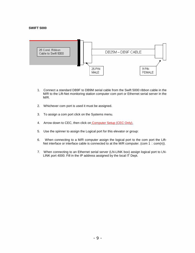
SWIFT 5000
1. Connect a standard DB9F to DB9M serial cable from the Swift 5000 ribbon cable in the M/R to the Lift-Net monitoring station computer com port or Ethernet serial server in the M/R.
2. Whichever com port is used it must be assigned.
3. To assign a com port click on the Systems menu.
4. Arrow down to CEC, then click on Computer Setup (CEC Only).
5. Use the spinner to assign the Logical port for this elevator or group:
6. When connecting to a M/R computer assign the logical port to the com port the Lift-Net interface or interface cable is connected to at the M/R computer. (com 1 – com(n)).
7. When connecting to an Ethernet serial server (LN-LINK box) assign logical port to LN-LINK port 4000. Fill in the IP address assigned by the local IT Dept.

10
Elevator Controls Corp.
Updated: 7/24/2004 10:57 PM
Verify controller software is Lift-Net compatible.
At the local controller address FCE0 = 08
At the group controller address A488 = 08
Connection From Controller or Group Supervisory to Lift-Net Monitoring Computer or LN-LINK Serial Server in Machine Room, when using a straight RS-232 connection. (less than 50 feet -15 meters).
1. Use DB9 Male to DB9 Female Straight Through Cable.
2. Connect one end to the Controller MPU board DB9 socket IBM. When a Group Supervisory Controller is present, connect to Supervisory MPU board DB9 socket IBM.
3. Connect the other end to the Monitoring Computer DB9 socket Com 1 or LN-LINK serial port. Connect additional bank or simplex controller to Com 2, etc. When multiple banks are being monitored each bank must use a discrete Com Port. Special hardware is required at the Monitoring Computer for More Than 2 Com Ports. Contact Tech Support.
4. LN-LINK DIP Switch Settings RS-232: sw1=OFF, sw2=ON, sw3=OFF
5. Whichever com port is used it must be assigned.
6. To assign a com port click on the Systems menu.
7. Arrow down to ELEVATOR CONTROLS, then click on Computer Setup (Elevator Controls Only).
8. Use the spinner to assign the Logical port for this computer to the com port that the straight through serial cable or Lift-Net RS422/232 Adapter is attached to.
9. When using a LN-LINK box assign logical port to LN-LINK port 4000. Fill in the IP address assigned by local IT Dept.
- 11 -
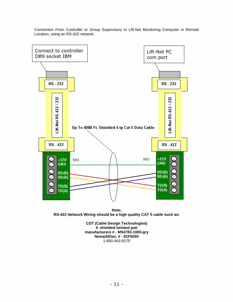
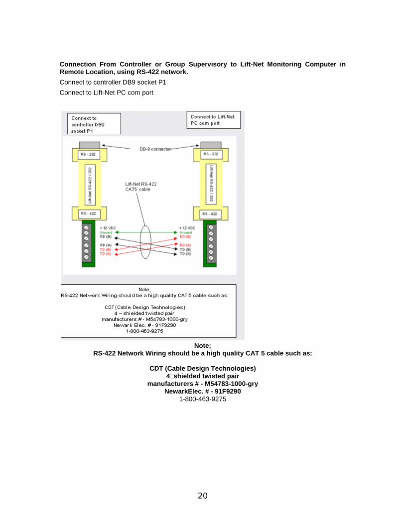
Connection From Controller or Group Supervisory to Lift-Net Monitoring Computer in Remote Location, using an RS-422 network.
Note;
RS-422 Network Wiring should be a high quality CAT 5 cable such as:
CDT (Cable Design Technologies) 4–shielded twisted pair
manufacturers # - M54783-1000-gry NewarkElec. # - 91F9290
1-800-463-9275
Connect to controller DB9 socket IBM
Lift-Net PC com port

12
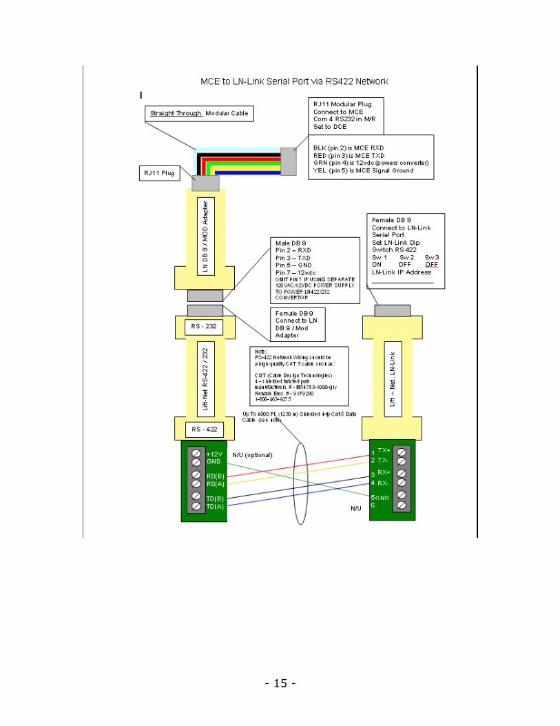
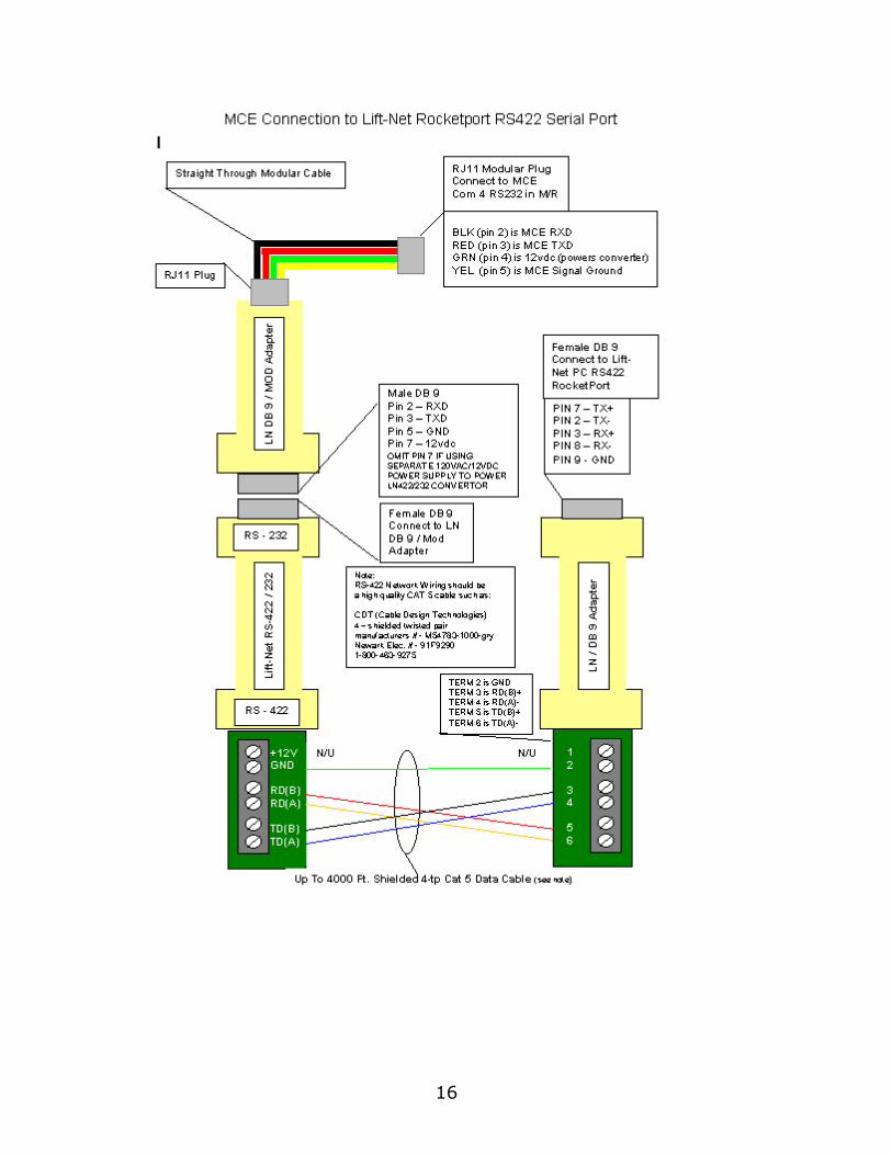
Motion Control Eng.
Updated: 7/24/2004 10:57 PM
Verify controller software is Lift-Net compatible.
From the MCE M3 Group Parameters screen (F1), select option 1 General.
Verify ICOM is set to MCE com port( 1-4) that is connected to Lift-Net PC. Set MCE com port switch to DCE.
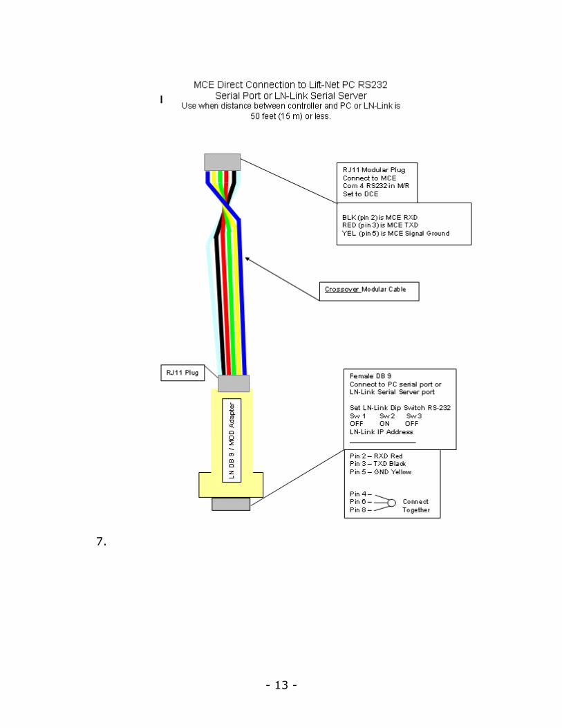
1. Connect the RJ-11 plug to the MCE Group Supervisory controller com 1-4. Connect the Lift-Net LN DB9 / MOD Adapter to the Lift-Net computer or LN-LINK serial port.
2. Whichever Lift-Net com port is used it must be assigned.
3. To assign a com port click on the Systems menu.
4. Arrow down to MOTION CONTROL, then click on Computer Setup (MCE Only).
5. Use the spinner to assign the Logical port for this computer to the com port that the Lift-Net RS422/232 or LN/DB9 Adapter is attached to.
6. When using a LN-LINK box assign logical port to LN-LINK port 4000. Fill in the IP address assigned by local IT Dept.
- 13 -
7.

14
- 15 -
16

- 17 -
Northern Interface
Updated: 7/24/2004 10:57 PM
Connection From Northern PC to Lift-Net Monitoring Computer or LN-LINK Serial Server in Machine Room, when using a straight RS-232 connection. (less than 50 feet -15 meters).
1. Use DB9 Male to DB9 Female Straight Through Cable.
2. Connect one end to the Northern PC.
3. Connect the other end to the Monitoring Computer or LN-LINK DB9 socket serial port. Connect additional bank or simplex controller to Com 2, etc. When multiple banks are being monitored each bank must use a discrete Com Port. Special hardware is required at the Monitoring Computer for More Than 2 Com Ports. Contact Tech Support.
4. LN-LINK DIP Switch Settings RS-232: sw1=OFF, sw2=ON, sw3=OFF
5. Whichever com port is used it must be assigned.
6. To assign a com port click on the Systems menu.
7. Arrow down to Northern, then click on Computer Setup (Northern Only).
8. Use the spinner to assign the Logical port for this computer to the com port that the straight through serial cable or Lift-Net RS422/232 Adapter is attached to.
9. When using a LN-LINK box assign logical port to LN-LINK port 4000. Fill in the IP address assigned by local IT Dept.
18
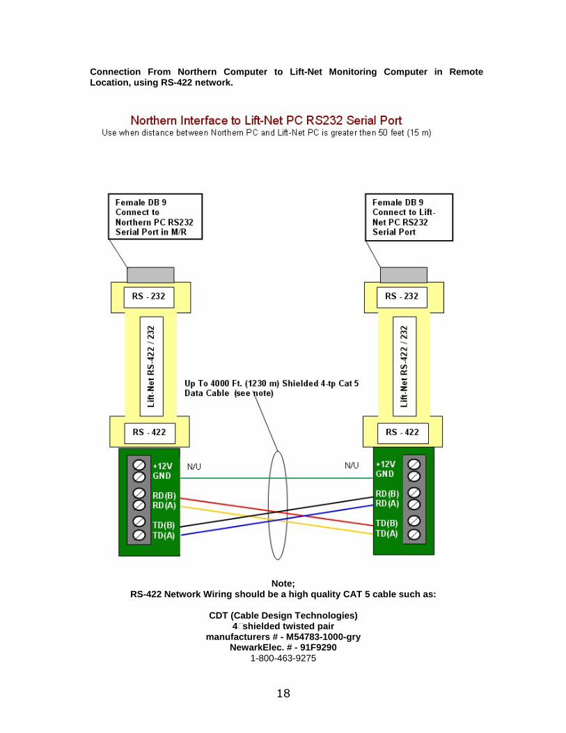
Connection From Northern Computer to Lift-Net Monitoring Computer in Remote Location, using RS-422 network.
Note; RS-422 Network Wiring should be a high quality CAT 5 cable such as:
CDT (Cable Design Technologies)
4–shielded twisted pair manufacturers # - M54783-1000-gry
NewarkElec. # - 91F9290 1-800-463-9275

- 19 -
O' Thompson
Updated: 7/24/2004 10:57 PM
Connection From Controller or Group Supervisory to Lift-Net Monitoring Computer or LN-LINK Serial Server in Machine Room, when using a straight RS-232 connection. (less than 50 feet -15 meters).
1. Use DB9 Female to DB9 Female Null Modem Cable.
2. Connect one end to the Controller MPU board DB9 socket P1. When a Group Supervisory Controller is present, connect to Supervisory MPU board DB9 socket P1.
3. Connect the other end to Monitoring Computer DB9 socket Com 1 or LN-LINK serial port. Connect additional bank or simplex controller to Com 2, etc. When multiple banks are being monitored each bank must use a discrete Com Port. Special hardware is required at the Monitoring Computer for More Than 2 Com Ports. Contact Tech Support
4. Whichever com port is used it must be assigned.
5. To assign a com port click on the Systems menu.
6. Arrow down to O THOMPSON, then click on Computer Setup (O Thompson Only).
7. Use the spinner to assign the Logical port for this computer to the com port that the Null Modem Cable or Lift-Net RS422/232 Interface is attached to.
8. When using a LN-LINK box assign logical port to LN-LINK port 4000. Fill in the IP address assigned by local IT Dept.
TECH NOTE: When a NULL MODEM CABLE is not available, a straight through DB9 Female to DB9 Female cable can be used. with a Null Modem Adapter installed at the Monitoring Computer Com Port.
20
Connection From Controller or Group Supervisory to Lift-Net Monitoring Computer in Remote Location, using RS-422 network.
Connect to controller DB9 socket P1
Connect to Lift-Net PC com port
Note;
RS-422 Network Wiring should be a high quality CAT 5 cable such as:
CDT (Cable Design Technologies) 4–shielded twisted pair
manufacturers # - M54783-1000-gry NewarkElec. # - 91F9290
1-800-463-9275

- 21 -
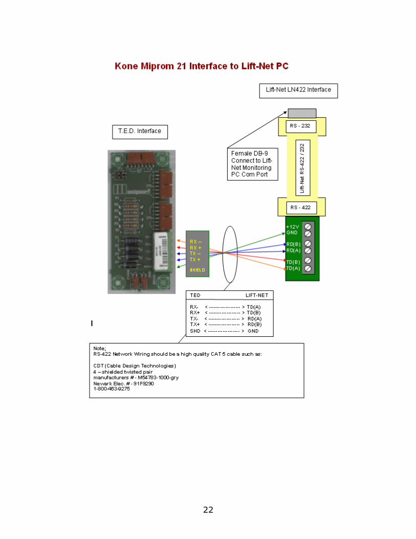
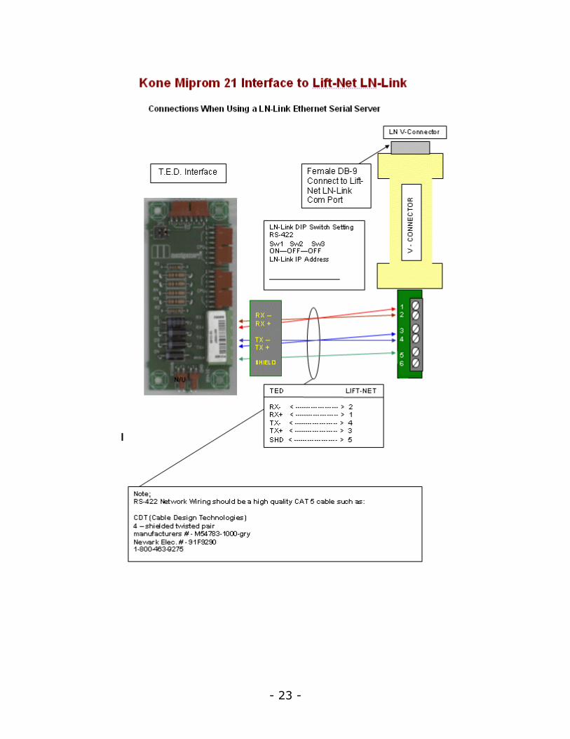
Kone Interface
Updated: 7/24/2004 10:57 PM
1. Wire the Lift-Net RS422/232 Interface to the MIPROM 21 T.E.D. Interface as detailed below.
2. Connect the DB-9 connector on the Lift-Net RS422/232 Interface to the monitoring station computer com port usually com 1 or LN-LINK serial port.
3. Whichever com port is used it must be assigned.
4. To assign a com port click on the Systems menu.
5. Arrow down to KONE, then click on Computer Setup (Kone Only).
6. Use the spinner to assign the Logical port for this computer to the com port that the Lift-Net RS422/232 or LN/DB9 Adapter is attached to.
7. When using a LN-LINK box assign logical port to LN-LINK port 4000. Fill in the IP address assigned by local IT Dept.
22
- 23 -

24
- 25 -
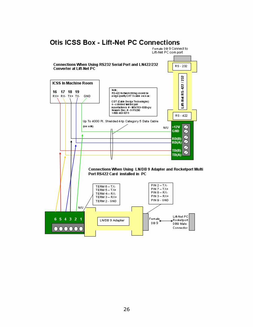
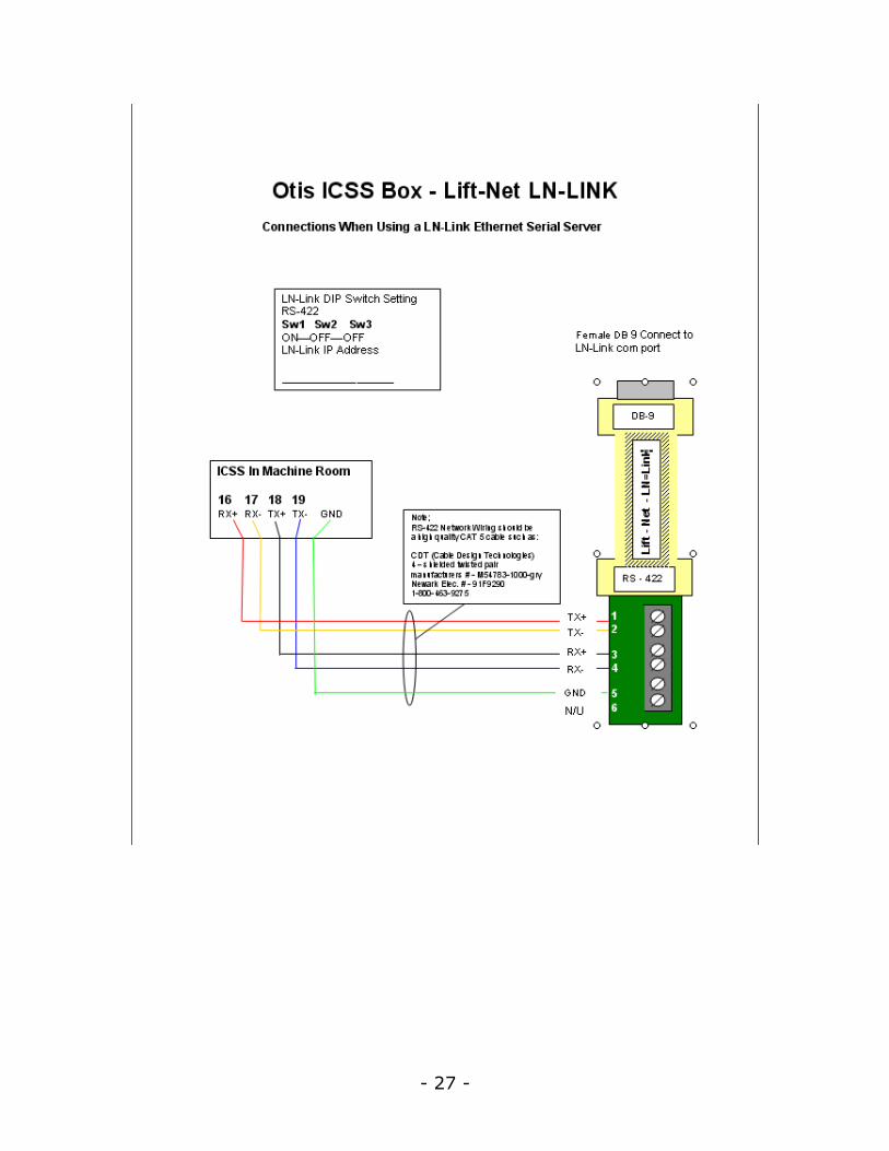
Otis_Interface
Updated: 7/24/2004 10:57 PM
1. Refer to drawings below for connection details.
2. Connect Lift-Net supplied DB9 adapter to the Monitoring Computer DB9 socket Com 1 or LN-LINK serial port. Connect additional bank or simplex controller to Com 2, etc. When multiple banks are being monitored each bank must use a discrete Com Port. Special hardware is required at the Monitoring Computer for More Than 2 Com Ports. Contact Tech Support.
3. Whichever com port is used it must be assigned.
4. To assign a com port click on the Systems menu.
5. Arrow down to Otis, then click on Computer Setup (Otis Only).
6. Use the spinner to assign the Logical port for this computer to the com port that the straight through serial cable or Lift-Net RS422/232 Adapter is attached to.
7. When using a LN-LINK box assign logical port to LN-LINK port 4000. Fill in the IP address assigned by local IT Dept.
26
- 27 -

28
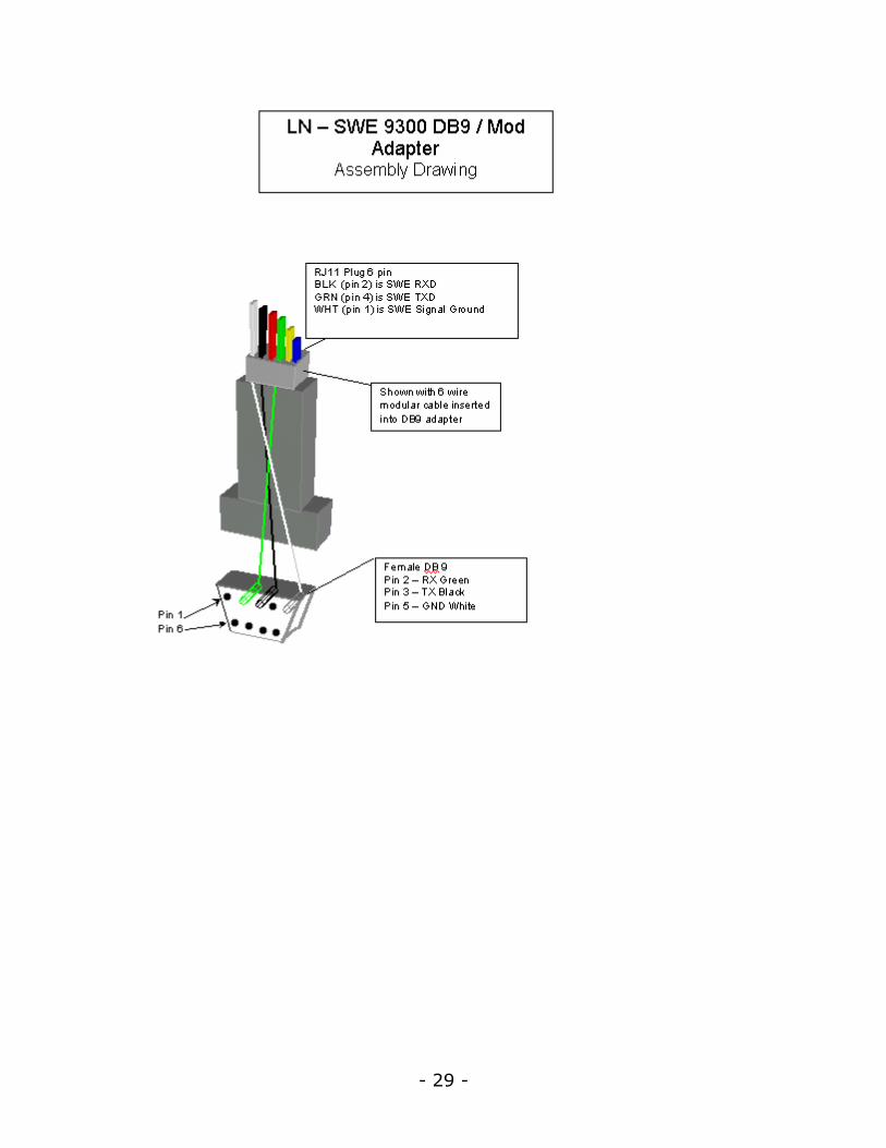
Schindler
Updated: 7/24/2004 10:57 PM
Lobby Vision
1. Connect the Lobby Vision Computer to the LAN/WAN.
2. At the Lift-Net Computer assign a com port, click on the Systems menu.
3. Arrow down to SCHINDLER, then click on Computer Setup (Schindler Only).
8. Use the spinner to assign the Logical port for this computer to Lobby Vision. Insert the assigned IP address.
SWE 9300 Escalator
Verify controller software is Lift-Net compatible.
Escalator controller parameters must be set to Lobby Vision. Consult Schindler documentation
1. Connect the female DB9 connector to the escalator controller.
2. Connect the RJ11 plug to the Lift-Net LNP card.
- 29 -
30
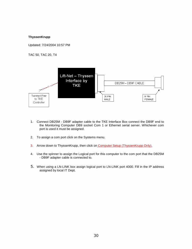
ThyssenKrupp
Updated: 7/24/2004 10:57 PM
TAC 50, TAC 20, T4
1. Connect DB25M - DB9F adapter cable to the TKE Interface Box connect the DB9F end to the Monitoring Computer DB9 socket Com 1 or Ethernet serial server. Whichever com port is used it must be assigned.
2. To assign a com port click on the Systems menu.
3. Arrow down to ThyssenKrupp, then click on Computer Setup (ThyssenKrupp Only).
4. Use the spinner to assign the Logical port for this computer to the com port that the DB25M - DB9F adapter cable is connected to.
5. When using a LN-LINK box assign logical port to LN-LINK port 4000. Fill in the IP address assigned by local IT Dept.
- 31 -
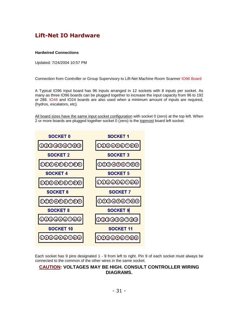
Lift-Net IO Hardware
Hardwired Connections
Updated: 7/24/2004 10:57 PM
Connection from Controller or Group Supervisory to Lift-Net Machine Room Scanner IO96 Board
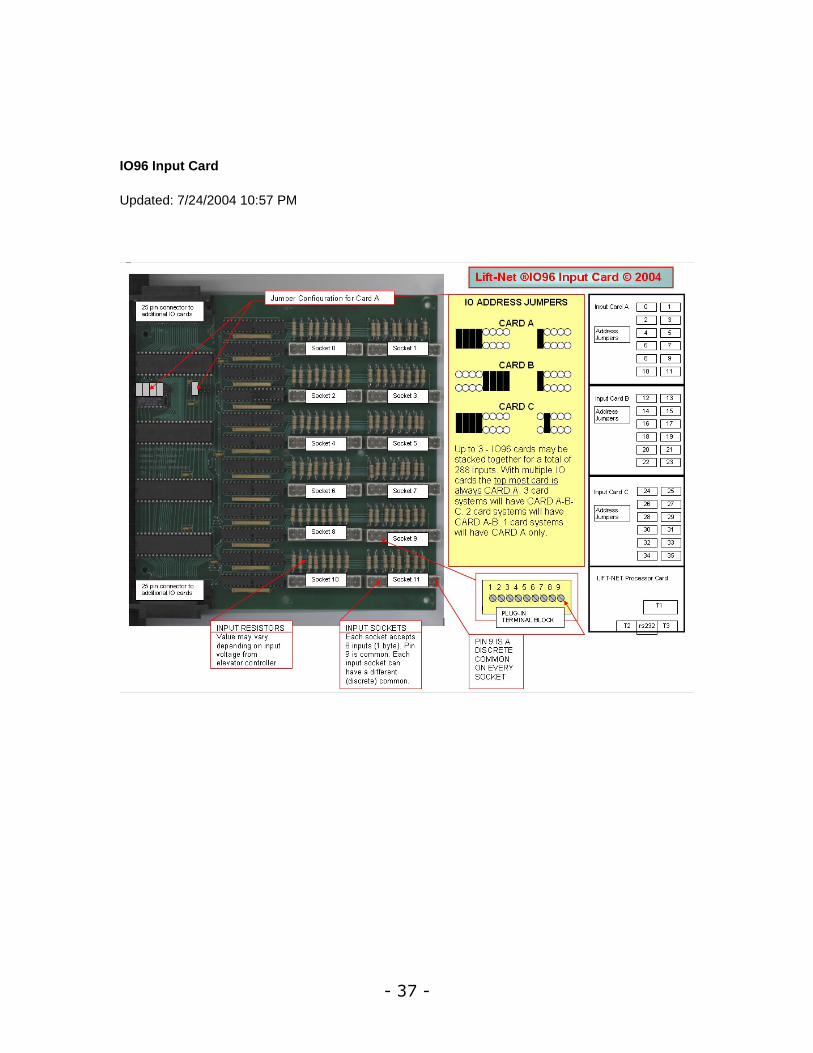
A Typical IO96 input board has 96 inputs arranged in 12 sockets with 8 inputs per socket. As many as three IO96 boards can be plugged together to increase the input capacity from 96 to 192 or 288. IO48 and IO24 boards are also used when a minimum amount of inputs are required, (hydros, escalators, etc).
All board sizes have the same input socket configuration with socket 0 (zero) at the top left. When 2 or more boards are plugged together socket 0 (zero) is the topmost board left socket.
Each socket has 9 pins designated 1 - 9 from left to right. Pin 9 of each socket must always be connected to the common of the other wires in the same socket.
CAUTION: VOLTAGES MAY BE HIGH. CONSULT CONTROLLER WIRING DIAGRAMS.

32
1. Make the input connections using the wiring sheets provided by IDS.
2. When the input connections have been completed, test the inputs by toggling the switch or device connected to each wire for that socket. Test all sockets that have field wires connected.
CAUTION: Each socket can have a separate common connected to pin 9. be certain the wire connected to pin 9 is the common for the wires
connected to pins 1 - 8.
3. Use the Input Status Display screen to verify that each status input is working. The Input Status Display screen is available from the Views menu. The input status may also be viewed from the Single Car View.
4. The hall button inputs can be checked by viewing the Hall Button screen. The hall button screen is available from the Views menu. The hall buttons may also be viewed from the Single Car View and the Expanded View.
- 33 -
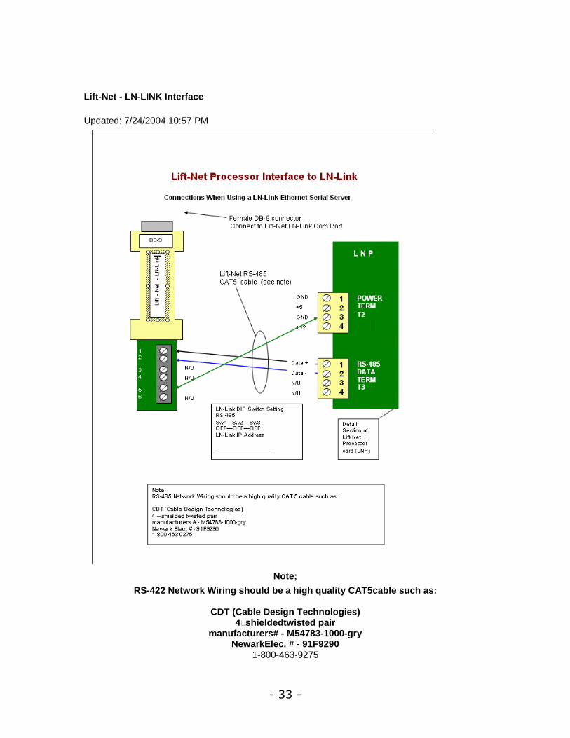
Lift-Net - LN-LINK Interface
Updated: 7/24/2004 10:57 PM
Note;
RS-422 Network Wiring should be a high quality CAT5cable such as:
CDT (Cable Design Technologies) 4–shieldedtwisted pair
manufacturers# - M54783-1000-gry NewarkElec. # - 91F9290
1-800-463-9275
34
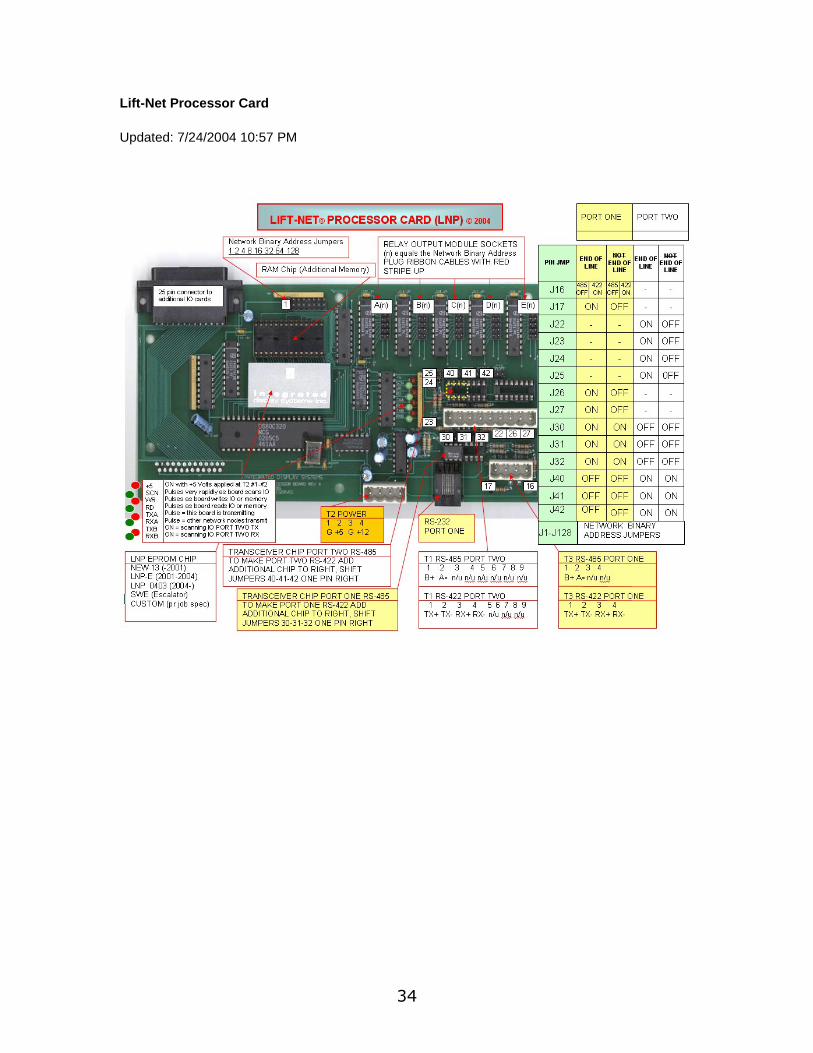
Lift-Net Processor Card
Updated: 7/24/2004 10:57 PM
- 35 -
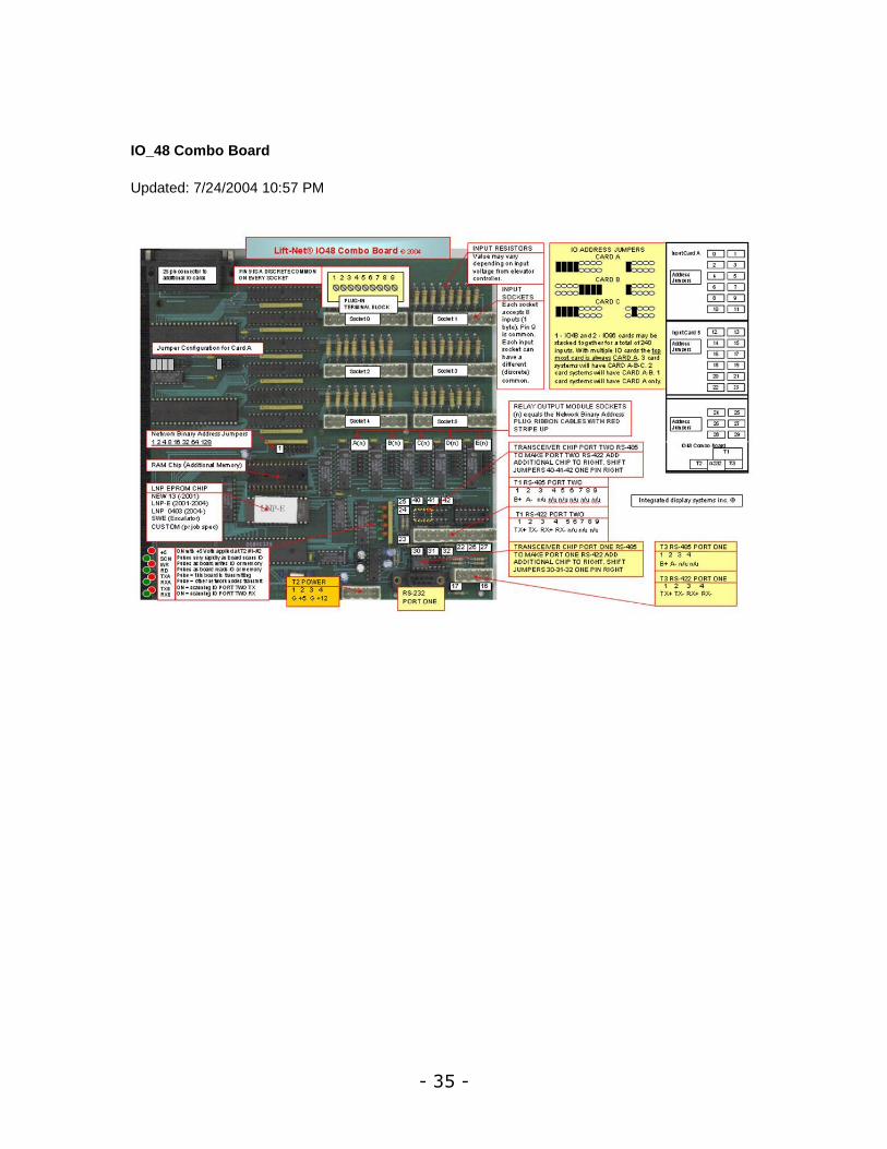
IO_48 Combo Board
Updated: 7/24/2004 10:57 PM
36
- 37 -
IO96 Input Card
Updated: 7/24/2004 10:57 PM
38
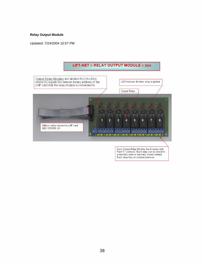
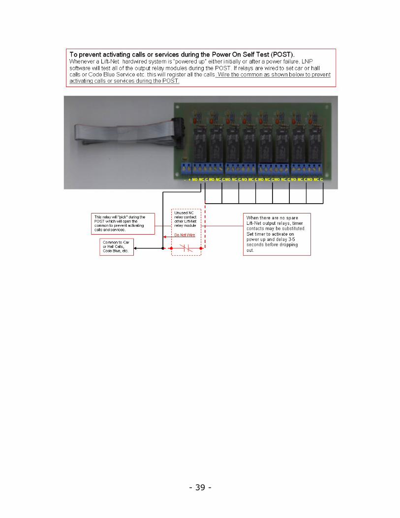
Relay Output Module
Updated: 7/24/2004 10:57 PM
- 39 -

40
Lift-Net Peripheals
Battery Backup
Updated: 7/24/2004 10:57 PM
All Lift-Net Monitoring computers shipped after January 2004 have a standard battery backup (UPS).
This unit acts to prevent over voltage (spikes) and under voltage (brown outs), by supplementing line power with a battery.
NOTE: During a complete power outage the standard battery backup will keep the Lift-Net computer running for a maximum of ten minutes (depending on system configuration).
During a power outage.
When the battery reaches a predetermined level all running programs will be closed and the computer will be shutdown.
When power is restored.
The computer will restart and the Lift-Net program will be opened.
If the computer does not restart after a power outage check the computer BIOS is set to turn on after power loss.
If the Lift-Net program does not restart after a power outage check the Windows startup folder for Lift-Net Monitoring.
- 41 -
De-Sensitizing Modules
Updated: 7/24/2004 10:57 PM
Under some conditions it may be necessary to monitor high voltage inputs on one or two sockets of a low voltage board.
Some controllers use high voltage circuits, 240 volts and higher.
This can present a problem when the OFF STATE voltage does not drop low enough to be seen by the input hardware.
Check for OFF STATE voltage at the plug on the Lift-Net IO board. Place your voltmeter leads from the input in question to pin 9.
Read the voltage in the active or ON STATE it must be 20 volts or more.
Read the voltage in the inactive or OFF STATE it must be less then 4 volts.
If the ON STATE is less than 20 volts, contact Tech Support.
If the OFF STATE is more than 4 volts install a de-sensitizing module between the input plug and the input socket.
De-sensitizing modules can be ganged in series.

42
Ethernet Serial Server
Updated: 7/24/2004 10:57 PM
Several brands of Ethernet serial servers are used in Lift-Net installations
LN-LINK
- 43 -
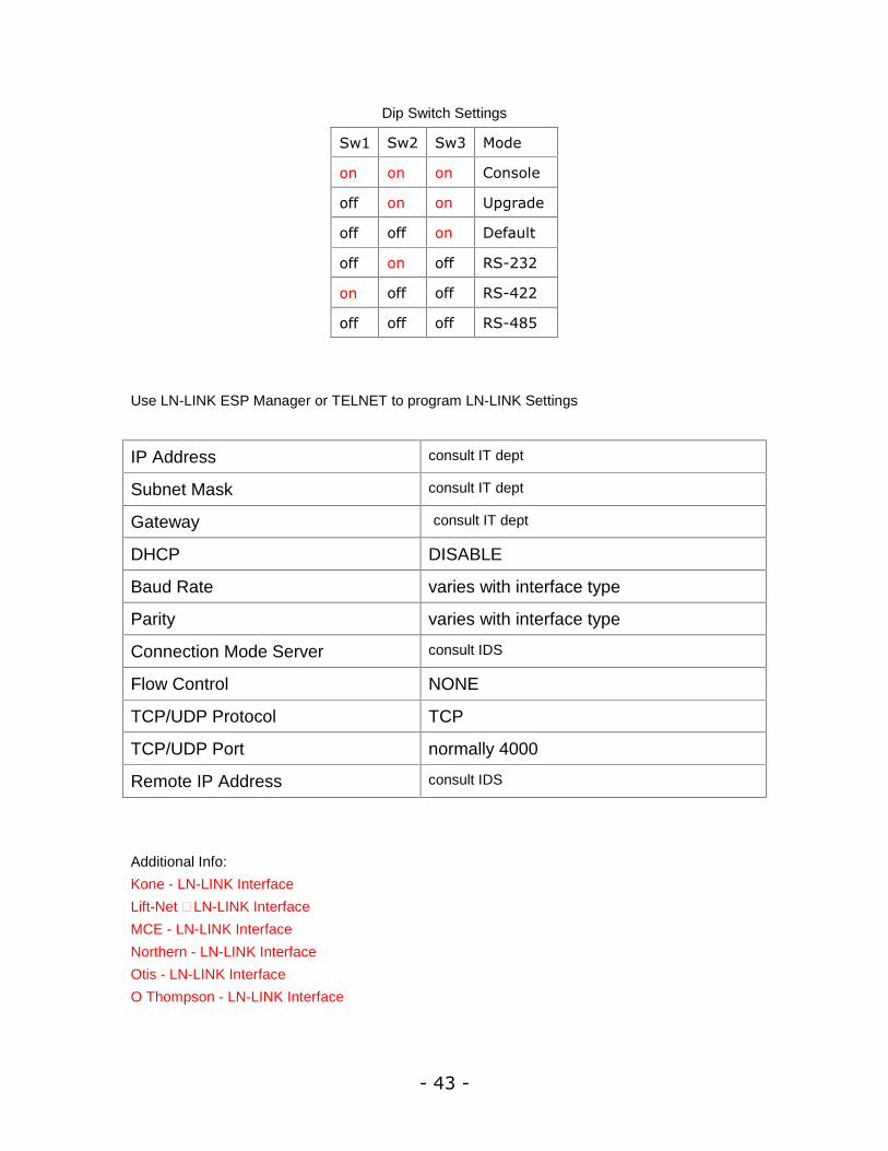
Dip Switch Settings
Sw1 Sw2 Sw3 Mode
on on on Console
off on on Upgrade
off off on Default
off on off RS-232
on off off RS-422
off off off RS-485
Use LN-LINK ESP Manager or TELNET to program LN-LINK Settings
IP Address consult IT dept
Subnet Mask consult IT dept
Gateway consult IT dept
DHCP DISABLE
Baud Rate varies with interface type
Parity varies with interface type
Connection Mode Server consult IDS
Flow Control NONE
TCP/UDP Protocol TCP
TCP/UDP Port normally 4000
Remote IP Address consult IDS
Additional Info:
Kone - LN-LINK Interface
Lift-Net – LN-LINK Interface
MCE - LN-LINK Interface
Northern - LN-LINK Interface
Otis - LN-LINK Interface
O Thompson - LN-LINK Interface
44
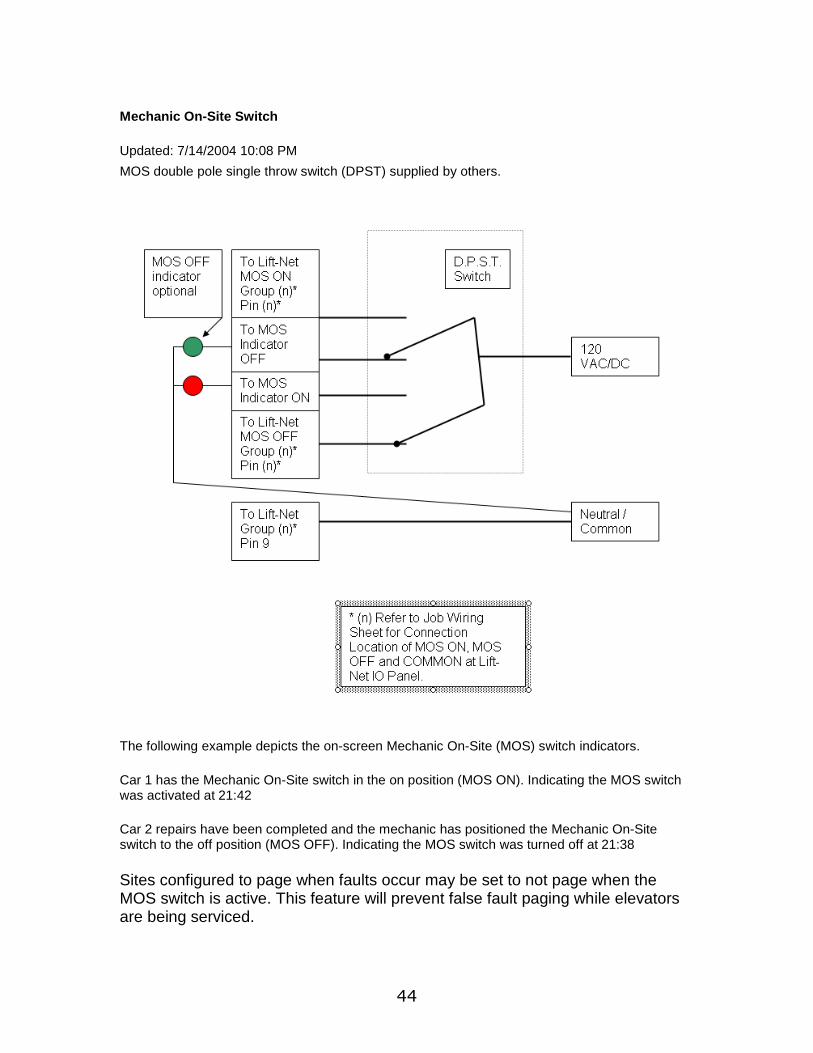
Mechanic On-Site Switch
Updated: 7/14/2004 10:08 PM
MOS double pole single throw switch (DPST) supplied by others.
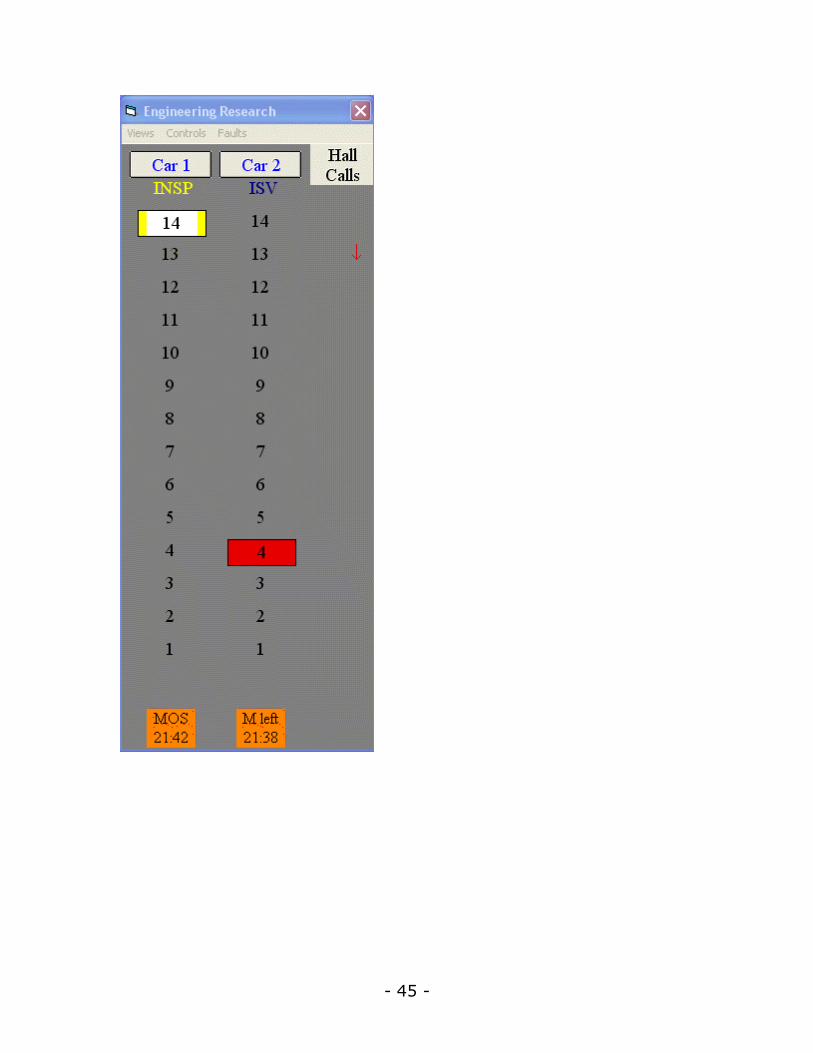
The following example depicts the on-screen Mechanic On-Site (MOS) switch indicators.
Car 1 has the Mechanic On-Site switch in the on position (MOS ON). Indicating the MOS switch was activated at 21:42
Car 2 repairs have been completed and the mechanic has positioned the Mechanic On-Site switch to the off position (MOS OFF). Indicating the MOS switch was turned off at 21:38
Sites configured to page when faults occur may be set to not page when the MOS switch is active. This feature will prevent false fault paging while elevators are being serviced.
- 45 -
46
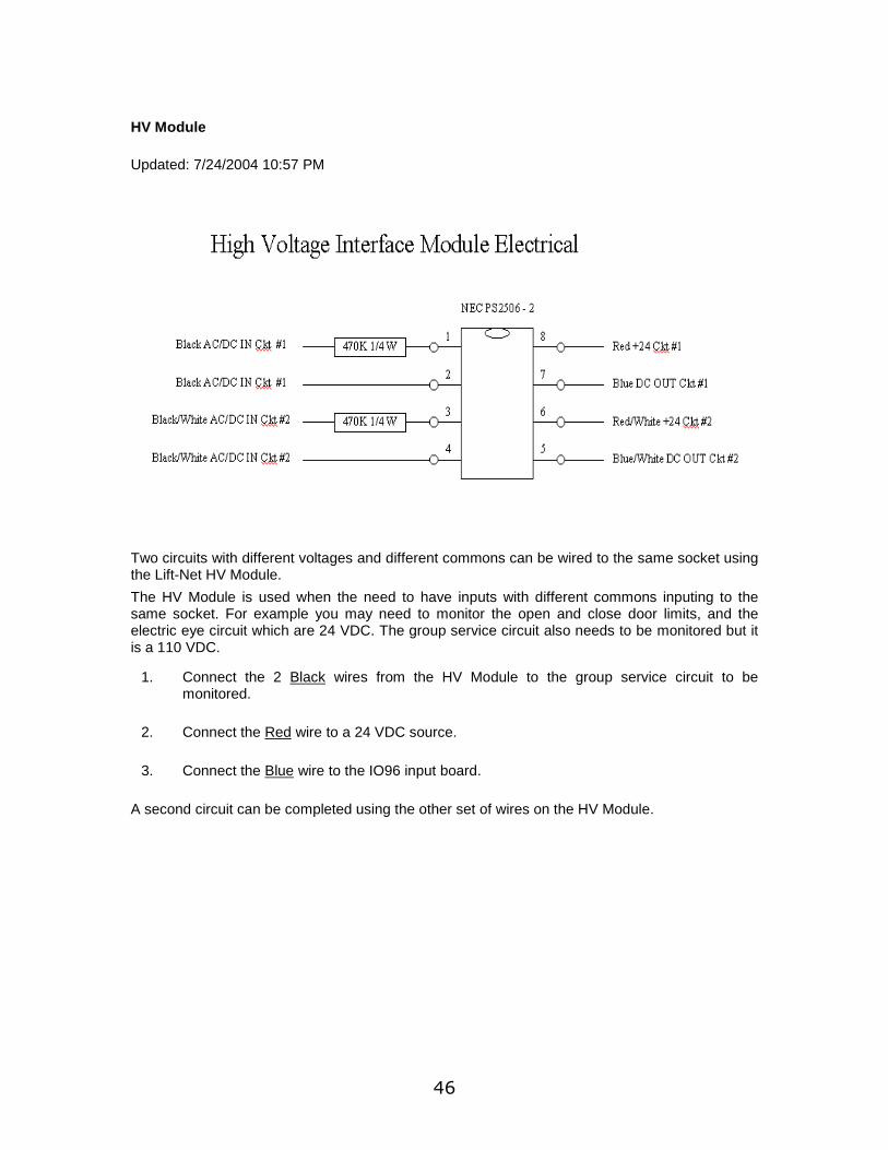
HV Module
Updated: 7/24/2004 10:57 PM
Two circuits with different voltages and different commons can be wired to the same socket using the Lift-Net HV Module.
The HV Module is used when the need to have inputs with different commons inputing to the same socket. For example you may need to monitor the open and close door limits, and the electric eye circuit which are 24 VDC. The group service circuit also needs to be monitored but it is a 110 VDC.
1. Connect the 2 Black wires from the HV Module to the group service circuit to be monitored.
2. Connect the Red wire to a 24 VDC source.
3. Connect the Blue wire to the IO96 input board.
A second circuit can be completed using the other set of wires on the HV Module.

- 47 -
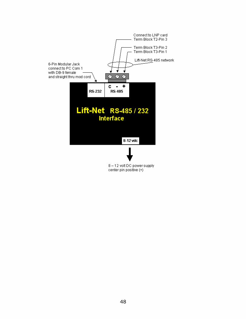
LN 485
Updated: 7/24/2004 10:57 PM
RS-485 / 232 Interface
Used with Lift-Net Hardwired Systems when distance is to great for a straight RS-232 connection (greater than 50 feet).
The Lift-Net Monitoring Computer receives data from the Lift-Net Machine Room Scanner via the Monitoring Computers RS-232 serial communications port.
RS-232 data begins to seriously degrade after 50 feet. Lift-Net hardware installations overcome this limitation by using a 2-wire RS-485 network which can travel distances up to 4000 ft.
Lift-Net M/R Scanner LNP cards output RS-485 data from terminal block T3. Pin 1 is positive (+), pin 2 is negative (-).
In order to convert the RS-485 data into RS-232 data, a protocol convertor is used where the monitoring computer connects to the Lift-Net network
Contact IDS Technical Support if you are unsure of the network protocol for your particular job.
48
- 49 -
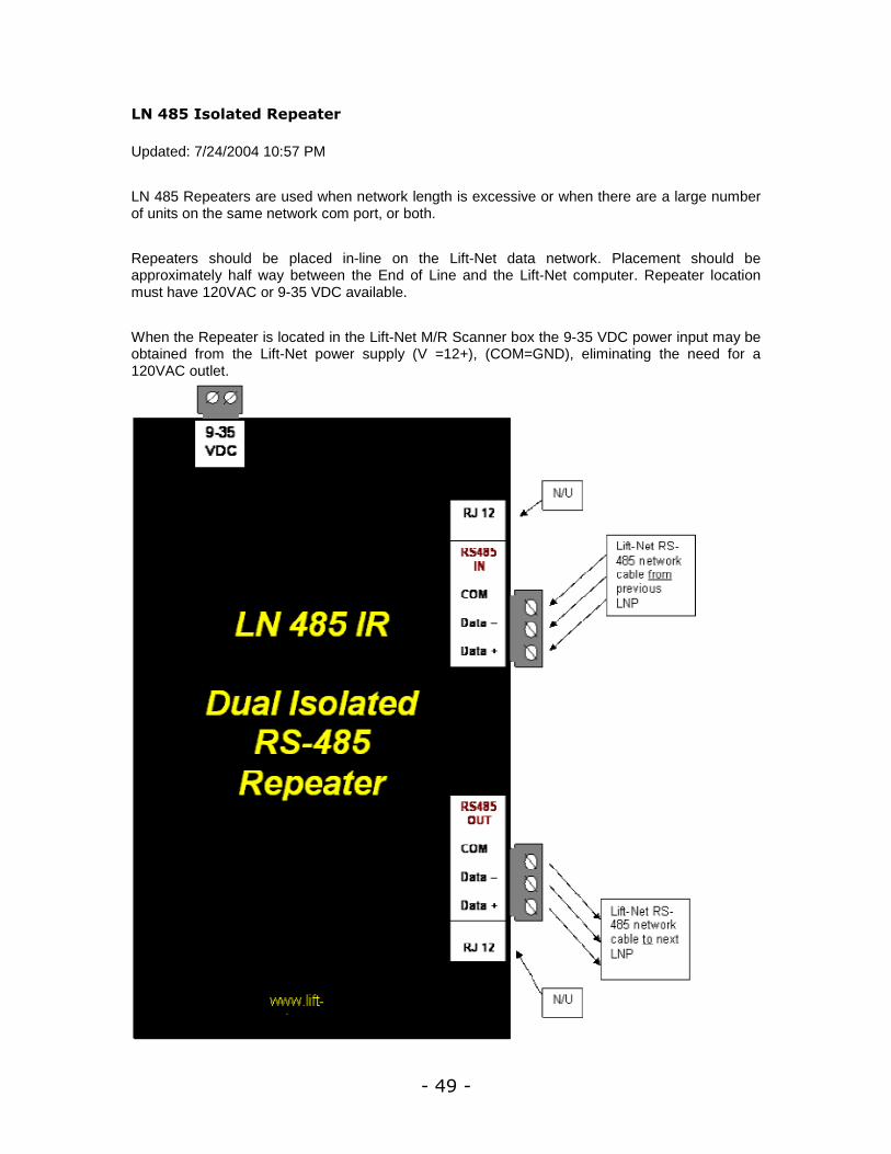
LN 485 Isolated Repeater
Updated: 7/24/2004 10:57 PM
LN 485 Repeaters are used when network length is excessive or when there are a large number of units on the same network com port, or both.
Repeaters should be placed in-line on the Lift-Net data network. Placement should be approximately half way between the End of Line and the Lift-Net computer. Repeater location must have 120VAC or 9-35 VDC available.
When the Repeater is located in the Lift-Net M/R Scanner box the 9-35 VDC power input may be obtained from the Lift-Net power supply (V =12+), (COM=GND), eliminating the need for a 120VAC outlet.

50
Computer Setup
This Computer Setup
CLICK ON
>> System >> This Computer Setup
- 51 -
Note: Some options illustrated above may not be available.
Fault and Service Alerts
CLICK ON
>> Monitor Faults
Use Monitor Faults to record fault data to the system hard disk. If this box is left blank, M/R scanners will continue to monitor for faults. No data will be saved.
Fault Alert
The user is able to choose the manner in which they are notified of a Fault Alert. The user can choose from 4 options below:
CLICK ON
>> No Alert - Choose this option to refrain from notifying the user of a Fault Alert.
>> Static - Choose this option to have a solid circle appear next to the elevator bank when there is a fault alert.
>> Blinking - Choose this option to have a blinking circle appear next to the elevator bank when there is a fault alert.
>> New Fault Form - Choose this option to have the most recent fault report brought up.
Service Byte Alerts
CLICK ON
>> Blink for Logged Servbyte Changes
This presents an alert every time an elevator changes service modes, such as when going from group service to independent service, or inspection, etc.
>> Audible Alert for Logged Servbyte Changes
This is used on systems that are monitoring a service byte. This feature will sound an alert whenever the car status changes.
>> Always show service status on Overhead View.
Playing Wave Files (all Alerts)
>> Seconds between alert sound scroll bar - Allows the user to choose the interval between alert sounds.
>> Stop alert sound after scroll bar - Allows the user to set how many times the alert sounds.
Controls
CLICK ON
>> Require Login before using any control screen
This will require a User to Login with their User ID and Password before being able to activate Elevator Controls.
52
>> No Relogin for Security Required
Once logged in, it will not be necessary to Login each time controls are accessed.
>> Allows Timed Controls on this computer
This enables the Elevator Controls that have been setup from the Timed Controls menu.
>> Allow more than one control form up at a time
>> Confirmation for Sending Carcalls
Check this box to have a confirmation message appear to verify a request for a car or hall call.
>> Single click for Hall and Car Calls
Check this box to eliminate having to double-click to place a car or hall call.
Traffic
CLICK ON
>> Write traffic, carstats, and grouplog data to disk
This will record the data being collected by the Lift-Net scanners to the monitoring computer hard disk.
>> Required wait time after last Hall Call before recording a new one.
Use the scroll bar to choose from No Wait to 10 seconds.
>> Exclude zero second traffic wait times (Default Setting)
Hall calls less than 1 second in duration will not be recorded.
>> Days of Traffic to Download scroll bar
Use the Days of Traffic to Download scroll bar to choose the number of days worth of traffic data from remote sites to download.
- 53 -
>> Weeks of Other Data to Download scroll bar
Use the Weeks of Other Data to Download scroll bar to choose the number of days worth of other data from remote sites to download.
Replay
CLICK ON
>> Replay Save On
Check this box to have the replay data saved to the system hard disk. Data will not be available for replay if this option is not checked. Data begins being saved from the time this feature is activated.
>> Weeks to Save Before Automatically Deleting Old scroll bar
Use the Weeks to Save Before Automatically Deleting Old scroll bar to decide how many weeks of replay data to keep on the monitoring system hard drive.
>> Use this computer to archive Replay Data check box
Other
CLICK ON
>> Use this computer to retrieve Reinstall Files
This option is to be used when Lift-Net is setup on multiple computers via a network. By selecting this option, a few computers can be designated to check all computers and compare which has the newest file. This is helpful in restoring or swapping information from one machine to another on the network.
Reinstall files are created each day at all sites. This zip files contains all the local information for a computer. If data is collected on a few computers, then in the event that a computer crashes, Lift-net and all of its settings would be able to be restored. The Reinstall files contain items such as:
security file
local option file
timed lockouts for the local computer
screen layout files
configuration file
port designation file
paging files.
>> Automatic reboot if Lift-Net fails (If Collecting Data)
>> Disallow printing even if printer available
>> Use military time for all time displays
This will change all time displays to a 24-hour format.
>> Center Lift-Net Error Messages

54
>> Hide Menu Bars (from Lobby Display, Alt - Shift - M)
This feature will hide all Menu Bars on the screen.
>> Initial View scroll bar
When more than one view is available, use the scroll bar to select which view is displayed on program start up.
CLICK ON
>> Save
This will save the current configuration to disk.
>> Cancel
This will Exit without changing anything.
>> Background Color
This will create a custom color for the Main Screen display.
>> Advanced
This includes some options that might not be applicable to certain jobs depending on things like the manufacturer, the use of escalators, the use of card readers, the use of moving elevators in the background, etc.
- 55 -
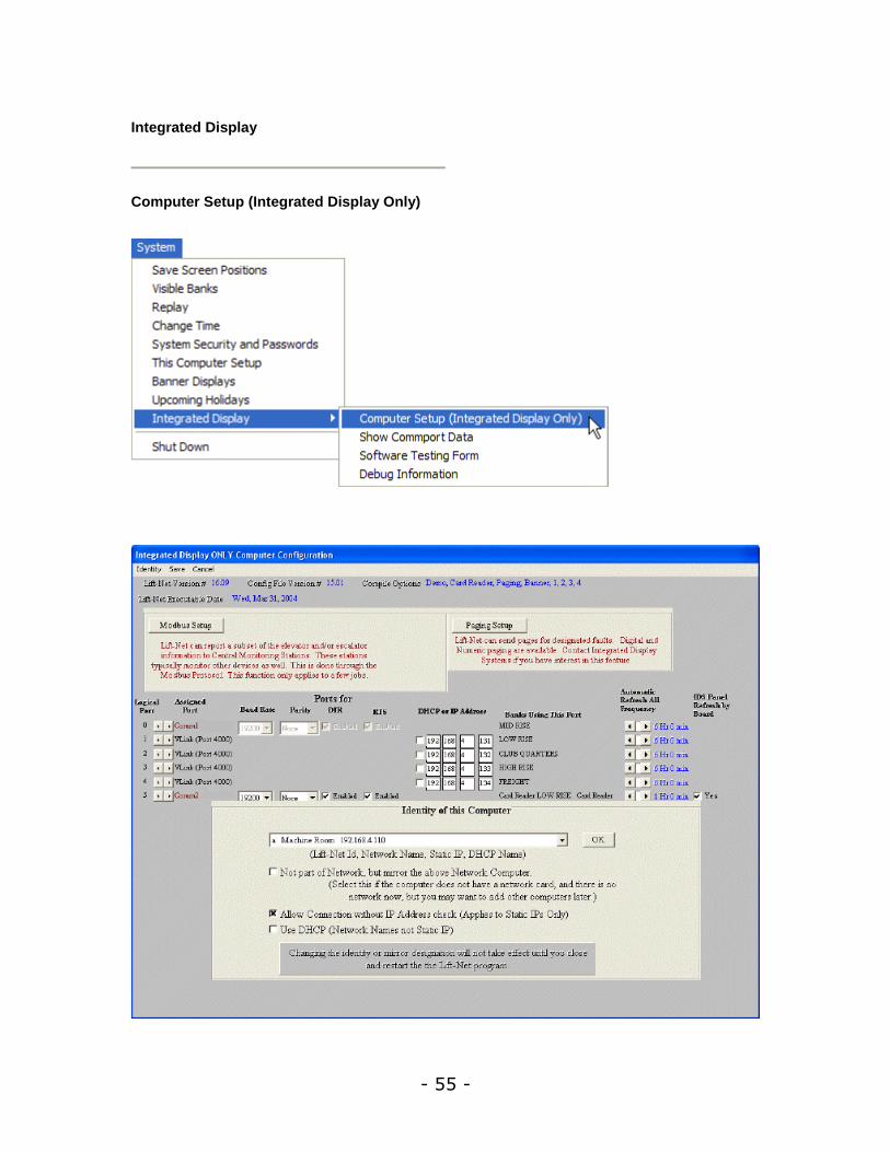
Integrated Display
Computer Setup (Integrated Display Only)
56
Modbus - Most installations do not report to a Modbus Network. Contact Lift-net Tech Support.
Logical Port
TA_2000 - Set to 0
Lift-Net and Lift-Net/LAN - set to 0, when using only 1 serial port. For multiple serial ports assign a unique logical port number for each. (see Assigned Port below)
Assigned Port - Use the scroll buttons to select an available com port.
TA_2000 - Most laptop computers will use com 1. Some laptop computers do not have a serial port. When a serial port is not available, a USB to serial port adapter is used. A USB to serial adapter will be connected to the laptop USB port at the opposite end will be a male DB9 connector. Use com 5 for this configuration. If you are unsure, you may identify valid serial ports by clicking the start menu, settings, control panel, device manager, ports.
Lift-Net and Lift-Net/LAN - When Lift-Net is serial linked to some multi-group systems (Otis, MCE, SWIFT FUTURA, etc.), more than one serial port may be used. Each group must be connected to a different serial port. For example, to assign a logical port to the car or group physically connected to serial port (com 1), use the scroll button to assign com 1 to the logical port. Assign a valid serial port to each logical port.
Baud Rate 9,600
SWIFT 5000 >> Set at 9,600
KONE >> Set at 9,600
O THOMPSON Set at 9,600
ThyssenKrupp >> Set at 9,600
Baud Rate 19,200
MCE >> Set at 19,200
OTIS >> Set at 19,200
ELEV CONTROLS CORP >> Set at 19,200
TA_2000 and 2000+, Lift-Net, Lift-Net/LAN >> Set at 19,200
SWIFT FUTURA >> Set at 19,200
Parity Even
Lift-Net Hardware Interface TA_2000 and 2000+ pre 05,2003 >> Set to EVEN.
Parity None
Lift-Net Hardware Interface TA_2000 and 2000+ after 04,2003 >> Set to NONE.
SWIFT FUTURA >> Set to NONE
SWIFT 5000 >> Set to NONE
MCE >> Set to NONE
ELEV CONTROLS CORP. >> Set to NONE

- 57 -
KONE >> Set to NONE
O THOMPSON >> Set to NONE
OTIS >> Set To NONE
ThyssenKrupp >> Set to NONE
DTR - Set to ENABLED
RTS - Set to ENABLED
If connecting to a LAN, click Identity to enter the Computer ID and IP Address
If not connecting to a LAN, choose a computer from the drop down list box. Check the box marked "Mirror The Above Computer".
Automatic Refresh All Frequency scroll bar: This will refresh lift-net data from this port at the interval selected. It is recommended to set this to refresh every 4-6 hours.
IDS Panel Refresh by Board check box: When using Lift-Net hardware interface check this box to have Lift-Net panels refresh in sequence at the refresh interval chosen.
Click Save to put these settings into effect.
Click Cancel to exit without saving changes
If the ERROR MESSAGE, "The Default Parity for IDS is Even", appears when attempting to save, Click OK. This warning refers to an earlier hardware version. Refer to Lift-Net hardware version pre 05,2003 even parity or after 04,2003 no parity.
TECH NOTE:
LOCATED AT THE TOP OF THE Lift-Net COMPUTER SETUP SCREEN IS INFORMATION REGARDING THE SOFTWARE INSTALLED ON THIS COMPUTER. THIS INFORMATION WILL ASSIST IDS TECHNICAL SUPPORT WITH YOUR QUESTIONS.
58
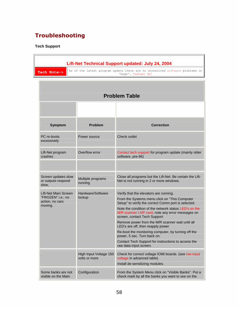
Troubleshooting
Tech Support
Lift-Net Technical Support updated: July 24, 2004
Tech Note-> As of the latest program update there are no unresolved software problems or "bugs". Contact Us!
Problem Table
Symptom Problem Correction
PC re-boots excessively
Power source
Check outlet
Lift-Net program crashes
Overflow error Contact tech support for program update (mainly older software, pre-96)
Screen updates slow or outputs respond slow,
Multiple programs running
Close all programs but the Lift-Net. Be certain the Lift-Net is not running in 2 or more windows.
Lift-Net Main Screen "FROZEN" i.e.; no action, no cars moving.
Hardware/Software lockup
Verify that the elevators are running. From the Systems menu click on "This Computer Setup" to verify the correct Comm port is selected. Note the condition of the network status LED's on the M/R scanner LNP card, note any error messages on screen, contact Tech Support Remove power from the M/R scanner wait until all LED's are off, then reapply power Re-boot the monitoring computer, by turning off the power, 5 sec. Turn back on. Contact Tech Support for instructions to access the raw data input screen.
. High Input Voltage 150 volts or more
Check for correct voltage IO96 boards. (see low input voltage in advanced table) Install de-sensitizing modules.
Some banks are not visible on the Main
Configuration From the System Menu click on "Visible Banks". Put a check mark by all the banks you want to see on the
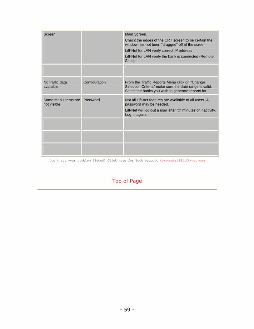
- 59 -
Screen Main Screen. Check the edges of the CRT screen to be certain the window has not been "dragged" off of the screen. Lift-Net for LAN verify correct IP address Lift-Net for LAN verify the bank is connected (Remote Sites)
No traffic data available
Configuration From the Traffic Reports Menu click on "Change Selection Criteria" make sure the date range is valid. Select the banks you wish to generate reports for.
Some menu items are not visible
Password Not all Lift-net features are available to all users. A password may be needed. Lift-Net will log-out a user after "x" minutes of inactivity. Log-in again.
Don't see your problem listed? Click here for Tech Support [email protected]
Top of Page
60
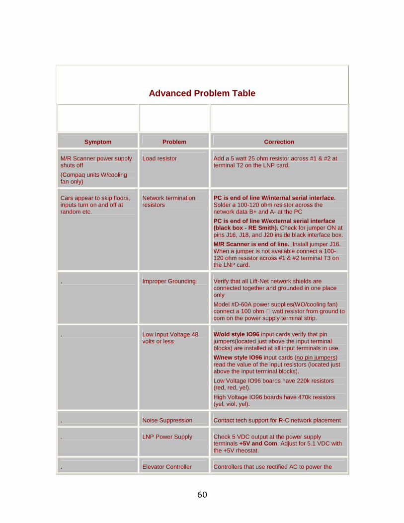
Advanced Problem Table
Symptom Problem Correction
M/R Scanner power supply shuts off (Compaq units W/cooling fan only)
Load resistor Add a 5 watt 25 ohm resistor across #1 & #2 at terminal T2 on the LNP card.
Cars appear to skip floors, inputs turn on and off at random etc.
Network termination resistors
PC is end of line W/internal serial interface. Solder a 100-120 ohm resistor across the network data B+ and A- at the PC PC is end of line W/external serial interface (black box - RE Smith). Check for jumper ON at pins J16, J18, and J20 inside black interface box. M/R Scanner is end of line. Install jumper J16. When a jumper is not available connect a 100-120 ohm resistor across #1 & #2 terminal T3 on the LNP card.
. Improper Grounding Verify that all Lift-Net network shields are connected together and grounded in one place only Model #D-60A power supplies(WO/cooling fan) connect a 100 ohm ½ watt resistor from ground to com on the power supply terminal strip.
. Low Input Voltage 48 volts or less
W/old style IO96 input cards verify that pin jumpers(located just above the input terminal blocks) are installed at all input terminals in use. W/new style IO96 input cards (no pin jumpers) read the value of the input resistors (located just above the input terminal blocks). Low Voltage IO96 boards have 220k resistors (red, red, yel). High Voltage IO96 boards have 470k resistors (yel, viol, yel).
. Noise Suppression Contact tech support for R-C network placement
. LNP Power Supply Check 5 VDC output at the power supply terminals +5V and Com. Adjust for 5.1 VDC with the +5V rheostat.
. Elevator Controller Controllers that use rectified AC to power the
- 61 -
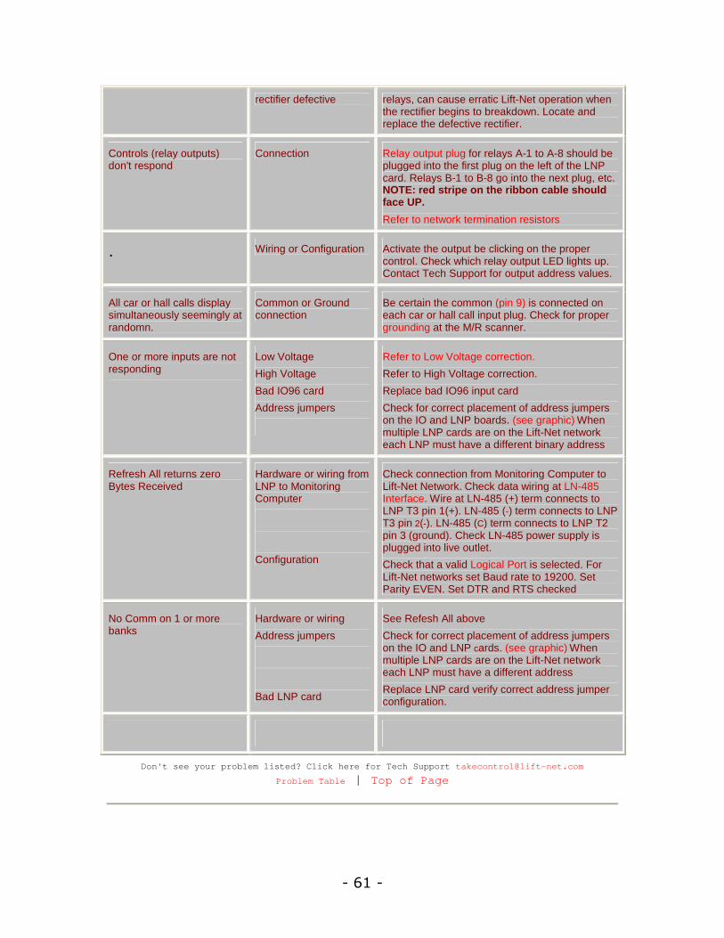
rectifier defective relays, can cause erratic Lift-Net operation when the rectifier begins to breakdown. Locate and replace the defective rectifier.
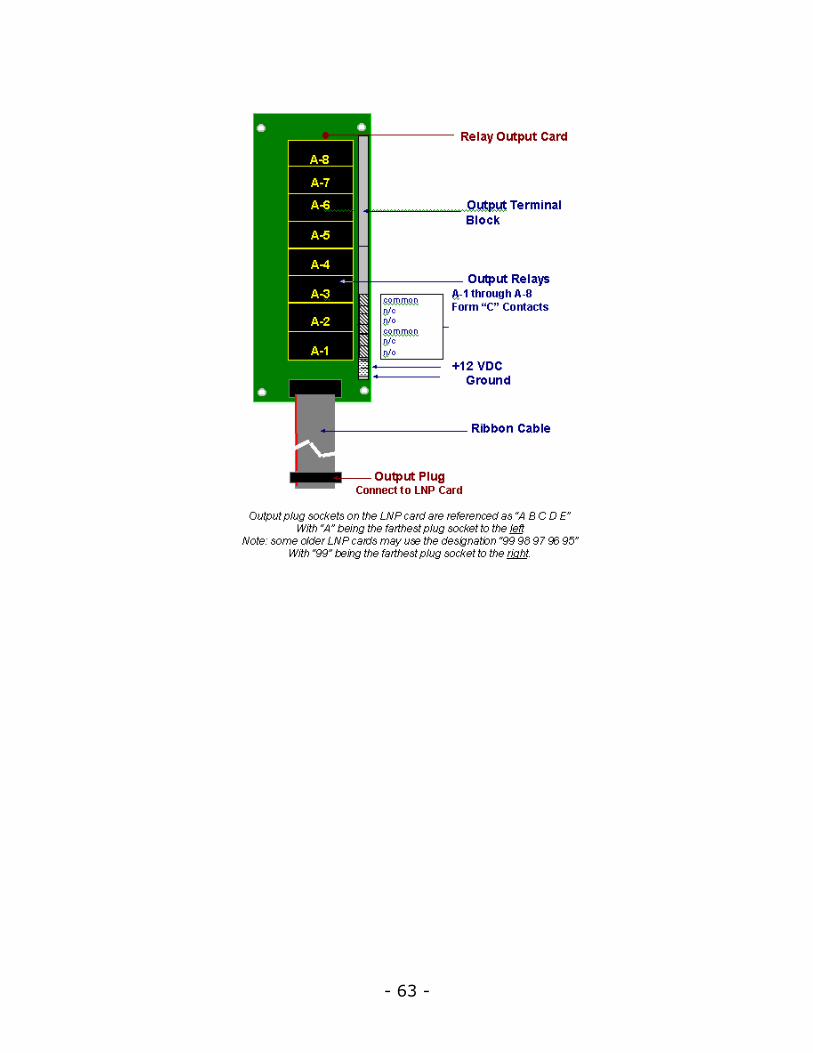
Controls (relay outputs) don't respond
Connection Relay output plug for relays A-1 to A-8 should be plugged into the first plug on the left of the LNP card. Relays B-1 to B-8 go into the next plug, etc. NOTE: red stripe on the ribbon cable should face UP. Refer to network termination resistors
. Wiring or Configuration Activate the output be clicking on the proper control. Check which relay output LED lights up. Contact Tech Support for output address values.
All car or hall calls display simultaneously seemingly at randomn.
Common or Ground connection
Be certain the common (pin 9) is connected on each car or hall call input plug. Check for proper grounding at the M/R scanner.
One or more inputs are not responding
Low Voltage High Voltage Bad IO96 card Address jumpers
Refer to Low Voltage correction. Refer to High Voltage correction. Replace bad IO96 input card Check for correct placement of address jumpers on the IO and LNP boards. (see graphic) When multiple LNP cards are on the Lift-Net network each LNP must have a different binary address
Refresh All returns zero Bytes Received
Hardware or wiring from LNP to Monitoring Computer
Configuration
Check connection from Monitoring Computer to Lift-Net Network. Check data wiring at LN-485 Interface. Wire at LN-485 (+) term connects to LNP T3 pin 1(+). LN-485 (-) term connects to LNP T3 pin 2(-). LN-485 (C) term connects to LNP T2 pin 3 (ground). Check LN-485 power supply is plugged into live outlet. Check that a valid Logical Port is selected. For Lift-Net networks set Baud rate to 19200. Set Parity EVEN. Set DTR and RTS checked
No Comm on 1 or more banks
Hardware or wiring Address jumpers
Bad LNP card
See Refesh All above Check for correct placement of address jumpers on the IO and LNP cards. (see graphic) When multiple LNP cards are on the Lift-Net network each LNP must have a different address Replace LNP card verify correct address jumper configuration.
Don't see your problem listed? Click here for Tech Support [email protected]
Problem Table | Top of Page
62
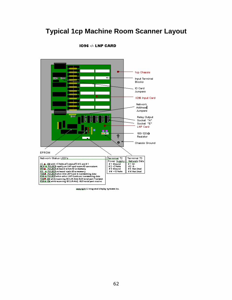
Typical 1cp Machine Room Scanner Layout
- 63 -
64
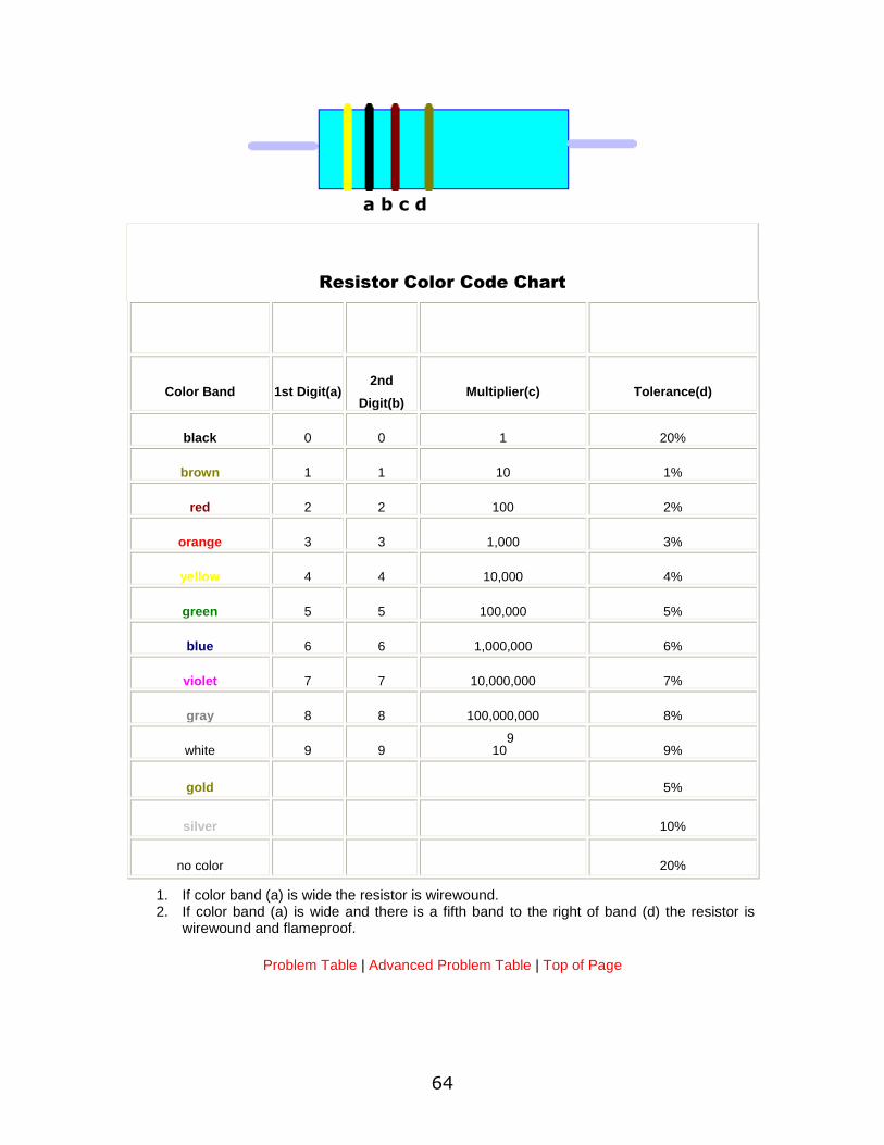
Resistor Color Code Chart
Color Band 1st Digit(a) 2nd
Digit(b) Multiplier(c) Tolerance(d)
black 0 0 1 20%
brown 1 1 10 1%
red 2 2 100 2%
orange 3 3 1,000 3%
yellow 4 4 10,000 4%
green 5 5 100,000 5%
blue 6 6 1,000,000 6%
violet 7 7 10,000,000 7%
gray 8 8 100,000,000 8%
white 9 9 109 9%
gold 5%
silver 10%
no color 20%
1. If color band (a) is wide the resistor is wirewound. 2. If color band (a) is wide and there is a fifth band to the right of band (d) the resistor is
wirewound and flameproof.
Problem Table | Advanced Problem Table | Top of Page
a b c d
- 65 -
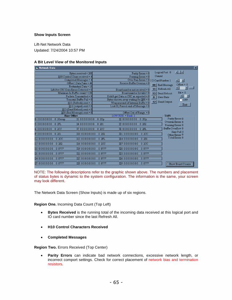
Show Inputs Screen
Lift-Net Network Data
Updated: 7/24/2004 10:57 PM
A Bit Level View of the Monitored Inputs
NOTE: The following descriptions refer to the graphic shown above. The numbers and placement of status bytes is dynamic to the system configuration. The information is the same, your screen may look different.
The Network Data Screen (Show Inputs) is made up of six regions.
Region One. Incoming Data Count (Top Left)
Bytes Received is the running total of the incoming data received at this logical port and IO card number since the last Refresh All.
H10 Control Characters Received
Completed Messages
Region Two. Errors Received (Top Center)
Parity Errors can indicate bad network connections, excessive network length, or incorrect comport settings. Check for correct placement of network bias and termination resistors.

66
Framing Errors can indicate bad network connections, excessive network length, or incorrect comport settings.
Overrun Errors
Region Three. Commands (Top Right)
Logical Port, use the horizontal scroll bar to select a logical port to view. When there is only one logical port the control will be disabled. When scrolling the logical ports the com port indicator will update, the base offset displayed just below Region One will update, the bank name and number displayed just below Region Two will update.
IO Card Number, use the horizontal scroll bar to select an IO card to view. When there is only one IO card the control will be disabled. When scrolling the IO cards the base offset displayed just below Region One will update, the bank name and number displayed just below Region Two will update.
Offset + (n), use the horizontal scroll bar to select a starting address offset (n). Click on the rectangular button to the right of the scroll bar and the selected address (n) of Incoming Data will be displayed in the top left position of Region Four. Subsequent addresses will follow, reading from left to right.
Bit Indicator use the horizontal scroll bar to select bit (0-7). Select an offset and a bit, use the check box to select off or on. Click the Send Output button to activate the control output or relay.
00 End Message
11 Refresh All, sends a signal to all the LNP cards on the Lift-Net network that are connected to the logical port currently selected. This signal clears the data buffer and zeros all the counters, then scans all the IO. A successful Refresh All for a system with 1 LNP card will return a minimum count of 188 in the bytes received counter (Region One). When the bytes received goes to zero after a refresh all and does not begin counting up, is an indication that there is no communication between the LNP card and the monitoring computer, be certain a valid logical port and offset are selected.
13 Send Reboot will reboot all the LNP cards on the Lift-Net network that are connected to the logical port currently selected.
0 Zero Stats will zero all the counters.
12 Send Output allows activating a control output or relay. (see Offset + (n) and Bit Indicator above.)
Region Four. Incoming Data Bit Level (Middle Left)
Input Status Indicators display the individual bits for every byte monitored. The first digit (at the left side) indicates this is byte number 0, socket 0. The eight digits grouped together in the middle is an 8 bit binary number representing the bits received at socket 0. 1 indicates the bit is high, 0 indicates the bit is low. The next set of digits displays the decimal equivalent of the eight digit binary number. The indicator at the left side is the

- 67 -
byte label. The byte label displays what is being monitored at that byte (socket), group status, up hall calls, status, etc.
All Bytes (sockets) 0 - (n) see above
Region Five. TAPI Errors (Middle Right)
Region Six. Board Counts (Bottom Left)
Use the Show Board Counts button to display active input boards.
68
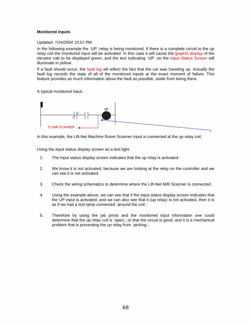
Monitored Inputs
Updated: 7/24/2004 10:57 PM
In the following example the “UP” relay is being monitored. If there is a complete circuit to the up relay coil the monitored input will be activated. In this case it will cause the graphic display of the elevator cab to be displayed green, and the text indicating “UP” on the Input Status Screen will illuminate in yellow.
If a fault should occur, the fault log wll reflect the fact that the car was traveling up. Actually the fault log records the state of all of the monitored inputs at the exact moment of failure. This feature provides as much information about the fault as possible, aside from being there.
A typical monitored input.
In this example, the Lift-Net Machine Room Scanner input is connected at the up relay coil.
Using the input status display screen as a test light.
1. The input status display screen indicates that the up relay is activated.
2. We know it is not activated, because we are looking at the relay on the controller and we can see it is not activated.
3. Check the wiring schematics to determine where the Lift-Net M/R Scanner is connected.
4. Using the example above, we can see that if the input status display screen indicates that the UP input is activated, and we can also see that it (up relay) is not activated, then it is as if we had a test lamp connected “around the coil”.
5. Therefore by using the job prints and the monitored input information one could determine that the up relay coil is “open”, or that the circuit is good, and it is a mechanical problem that is preventing the up relay from “picking”.

- 69 -
Contact Info
Main Office
Integrated Display Systems Inc.
1555 Sherman Avenue, #170
Evanston, IL 60201
USA
Technical Support
Voice: (847) 475-2476
Fax: (847) 475-2535
Email: [email protected]
Internet: http://www.lift-net.com
Send return items for warranty repair to:
Integrated Display Systems Inc.
5130 B West 16th Street
Cicero, IL 60804
USA
Windows is a trademark of Microsoft Corp.
Lift-Net, Lift-Net Voice, and TA_2000 are trademarks of Integrated Display Systems Inc.
integrated display systems inc. © 2004


71
Index C
CAUTION.............................31
Connection From Northern PC 17 D
DE-SENSITIZING MODULES .....41 H
HARDWIRED CONNECTIONS..31 I
IO Card Wiring ...................... 2
IO_48 Combo Board .............35 K
K0NE_INTERFACE .................21 L
LAN OVERALL VIEW............... 5 Lift-Net RS-422 NETWORK
OVERVIEW ......................... 3 Lift-Net RS-485 NETWORK
OVERVIEW ......................... 4 M
MCE M3 Group Parameters ....12
MIPROM 21 T.E.D...................21
MOTION CONTROL ENG ........12 N
Network Wiring ..................... 2
Northern Interface................17 O
Otis_Interface......................25 R
Relay Output Module ............38
RS-232 ................................47
RS-485 ................................47 S
Schindler ..............................28
Splices................................. 2 T
Termination’s........................ 2
ThyssenKrupp......................30 V
Vlinx Interface .....................33 W
WIRING CONSIDERATIONS .... 2


![Touch Display Link ver 2 · If Version 1.0 is already installed, tap [Google Play] or [Play Store], and then upgrade Touch Display Link. For details, refer to the manuals that come](https://img.pdfslide.us/doc/110x75/5fef0c6251d2cb460169d828/touch-display-link-ver-2-if-version-10-is-already-installed-tap-google-play.jpg)