Embed Size (px)
Citation preview
Abstract—Flying wing configuration has become an ideal
configuration of the future unmanned aerial vehicles, and it has
become the research hotspot of advanced aircraft in recent years.
In this article, an optimization strategy is constructed to deal
with the aerodynamic and stealthy multidisciplinary design
optimization issue of double-swept flying wing aircraft. In order
to describe the aircraft accurately, two methods are used to
parametric the airfoil profiles of the aircraft CAD model with
different leading edge shapes. For the two parametric
approaches, geometric parameters of the airfoil are used to
define its shape functions. It is analyzed that the parameters of
the aircraft impact on aerodynamic performance and
stealth capability, which is helpful to improve design. In
applying the strategy, the optimization algorithm combining
global optimization and gradient algorithm is adopted to search
for the optimum design. The optimization results indicate that
the optimization strategy can be implemented automatically,
and reasonable results are obtained.
Index Terms—aerodynamic, stealthy, parametric approach,
optimization algorithm
I. INTRODUCTION
Ailless flying wing configuration aircraft have potential
benefits over conventional configurations in stealth
capability and aerodynamic and structural efficiency [1, 2]
because of their simple shape. Flying wing aircraft have
attracted wide interest in both military and civilian fields, and
they have become the research hotspot of advanced aircraft
[3]. Several next-generation civil transport aircraft and
unmanned air vehicles (UAVs) are of flying wing designs.
Civilian flying wing aircraft include the Boeing X-48, the low
noise transporter developed by Cranfield University, the
flying wing aircraft in the studied by the Russian Central
Aerohydrodynamic Institute (TsAGI), and the 250-seat flying
wing concept in Beihang University. In the field of military
Manuscript received December 08, 2016; revised December 20, 2016.
Yalin Pan is with the School of Aeronautic Science and Engineering,
Beihang University. 37 Xueyuan Road, Haidian District, Beijing 100191,
China (corresponding author to provide phone: +86 18811791567; e-mail:
Jun Huang is with the School of Aeronautic Science and Engineering,
Beihang University. 37 Xueyuan Road, Haidian District, Beijing 100191,
China (e-mail: [email protected]).
Feng Li is with China Academy of Aerospace Aerodynamics. 17
Yungang West Road, Fengtai District, Beijing 100074, China (e-mail:
Chuxiong Yan is with the School of Aeronautic Science and Engineering,
Beihang University. 37 Xueyuan Road, Haidian District, Beijing 100191,
China (e-mail: [email protected]).
aviation, several countries have developed UCAV with tailless
configurations, such as the X-45, X-47B, nEURO, etc [4]. Flying wing configuration has become an ideal configuration of
the future unmanned aerial vehicles [5].
The lack of statistics and practical experience about flying
wing configuration aircraft posed great difficulties in aircraft
conceptual design. Multidisciplinary design optimization
(MDO) has been proved to be a promising method to solve
this kind of problem, which has been widely used in
conventional airplane design [6-9]. Flying wing aircraft have
the characteristics of simple shape and blended wing body,
which made it easily to parametric its CAD model shape.
The aim of this article is to propose a systematical method
to deal with aerodynamic and stealthy MDO issue for
double-swept wing configuration of an unmanned flying wing
aircraft conceptual design.
II. PARAMETRIC CAD MODEL
As for all optimization tasks, the complexity of the problem
is directly coupled to the parameterization of the geometry. Of
highest relevance is the number of parameters that are
required to ensure valid modeling. The most important
characteristic of the CAD model is to be highly flexible in
order to be able to represent a variety of designs as large as
possible. Secondly the model must be robust and reliable,
since there will not be a specialist manually entering new
parameters and supervising the update process [10].
Double-swept flying wing aircraft can be seen as a special
wing which is connected together by three segments. The
parameters defining this configuration can be grouped into
three sets.
A. Parameters for Aircraft Outline
These parameters are used to describe the plane shape,
including reference area of aircraft ( Sref ), wing aspect ratio
( Ar ), root chord length of inner wing ( br ), root chord
length of outer wing ( 2b ), semi span of inner wing ( 1l ),
leading edge swept angle of inner wing ( 1alpha ), and
leading edge swept angle of outer wing ( 2alpha ), as shown
in Figure 1. All the other outline parameters which are
displayed in Figure 1 can be derived from the above
mentioned parameters. The platform of the UAV is defined by
these parameters.
Integrated Design Optimization of Aerodynamic
and Stealthy Performance for Flying Wing
Aircraft
Yalin Pan, Jun Huang, Feng Li, and Chuxiong Yan
T
Proceedings of the International MultiConference of Engineers and Computer Scientists 2017 Vol II, IMECS 2017, March 15 - 17, 2017, Hong Kong
ISBN: 978-988-14047-7-0 ISSN: 2078-0958 (Print); ISSN: 2078-0966 (Online)
IMECS 2017
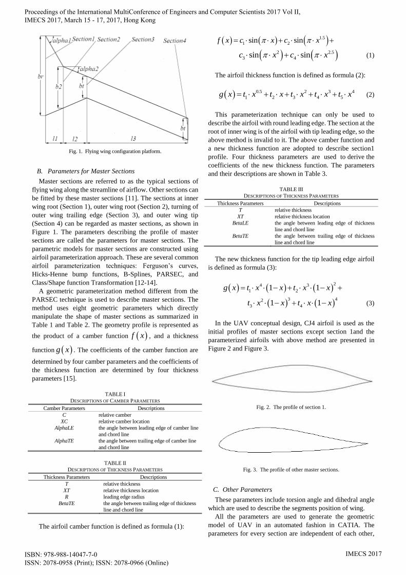
Fig. 1. Flying wing configuration platform.
B. Parameters for Master Sections
Master sections are referred to as the typical sections of
flying wing along the streamline of airflow. Other sections can
be fitted by these master sections [11]. The sections at inner
wing root (Section 1), outer wing root (Section 2), turning of
outer wing trailing edge (Section 3), and outer wing tip
(Section 4) can be regarded as master sections, as shown in
Figure 1. The parameters describing the profile of master
sections are called the parameters for master sections. The
parametric models for master sections are constructed using
airfoil parameterization approach. These are several common
airfoil parameterization techniques: Ferguson’s curves,
Hicks-Henne bump functions, B-Splines, PARSEC, and
Class/Shape function Transformation [12-14].
A geometric parameterization method different from the
PARSEC technique is used to describe master sections. The
method uses eight geometric parameters which directly
manipulate the shape of master sections as summarized in
Table 1 and Table 2. The geometry profile is represented as
the product of a camber function f x , and a thickness
function g x . The coefficients of the camber function are
determined by four camber parameters and the coefficients of
the thickness function are determined by four thickness
parameters [15].
TABLE I
DESCRIPTIONS OF CAMBER PARAMETERS
Camber Parameters Descriptions
C relative camber
XC relative camber location
AlphaLE the angle between leading edge of camber line
and chord line
AlphaTE the angle between trailing edge of camber line
and chord line
TABLE II
DESCRIPTIONS OF THICKNESS PARAMETERS
Thickness Parameters Descriptions
T relative thickness
XT relative thickness location
R leading edge radius
BetaTE the angle between trailing edge of thickness
line and chord line
The airfoil camber function is defined as formula (1):
1.5
1 2sin sinf x c x c x
2 2.5
3 4sin sinc x c x (1)
The airfoil thickness function is defined as formula (2):
0.5 2 3 4
1 2 3 4 5g x t x t x t x t x t x (2)
This parameterization technique can only be used to
describe the airfoil with round leading edge. The section at the
root of inner wing is of the airfoil with tip leading edge, so the
above method is invalid to it. The above camber function and
a new thickness function are adopted to describe section1
profile. Four thickness parameters are used to derive the
coefficients of the new thickness function. The parameters
and their descriptions are shown in Table 3.
TABLE III
DESCRIPTIONS OF THICKNESS PARAMETERS
Thickness Parameters Descriptions
T relative thickness
XT relative thickness location
BetaLE the angle between leading edge of thickness
line and chord line
BetaTE the angle between trailing edge of thickness
line and chord line
The new thickness function for the tip leading edge airfoil
is defined as formula (3):
24 3
1 21 1g x t x x t x x
3 42
3 41 1t x x t x x (3)
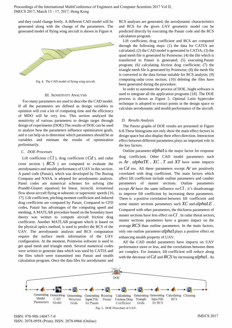
In the UAV conceptual design, CJ4 airfoil is used as the
initial profiles of master sections except section 1and the
parameterized airfoils with above method are presented in
Figure 2 and Figure 3.
Fig. 2. The profile of section 1.
Fig. 3. The profile of other master sections.
C. Other Parameters
These parameters include torsion angle and dihedral angle
which are used to describe the segments position of wing.
All the parameters are used to generate the geometric
model of UAV in an automated fashion in CATIA. The
parameters for every section are independent of each other,
Proceedings of the International MultiConference of Engineers and Computer Scientists 2017 Vol II, IMECS 2017, March 15 - 17, 2017, Hong Kong
ISBN: 978-988-14047-7-0 ISSN: 2078-0958 (Print); ISSN: 2078-0966 (Online)
IMECS 2017
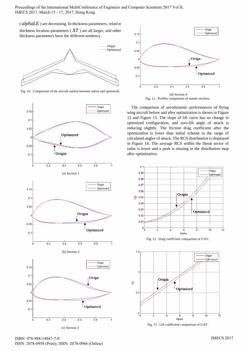
and they could change freely. A different CAD model will be
generated along with the change of the parameters. The
generated model of flying wing aircraft is shown in Figure 4.
Fig. 4. The CAD model of flying wing aircraft.
III. SENSITIVITY ANALYSIS
Too many parameters are used to describe the CAD model.
If all the parameters are defined as design variables to
optimize will cost a lot of computing time and the efficiency
of MDO will be very low. This section analyzed the
sensitivity of various parameters to design target through
design of experiments (DOE).The results of DOE can be used
to analyze how the parameters influence optimization goals,
and it can help us to determine which parameters should be as
variables and estimate the results of optimization
preliminarily.
C. DOE Processes
Lift coefficient ( Cl ), drag coefficient ( Cd ), and radar
cross section ( RCS ) are computed to evaluate the
aerodynamics and stealth performance of UAV in this section.
A panel code (Panair), which was developed by The Boeing
Company and NASA, is adopted for aerodynamic analysis.
Panel codes are numerical schemes for solving (the
Prandtl-Glauert equation) for linear, inviscid, irrotational
flow about aircraft flying at subsonic or supersonic speeds [16,
17]. Lift coefficient, pitching moment coefficient and induced
drag coefficient are computed by Panair. Compared to CFD
codes, Panair has advantages of the computing speed and
meshing. A MATLAB procedure based on the boundary layer
theory was written to compute aircraft friction drag
coefficient. Another MATLAB program which is based on
the physical optics method, is used to predict the RCS of the
UAV. The aerodynamic analysis and RCS computation
require the surface mesh information of the UAV
configuration. At the moment, Pointwise software is used to
get quad mesh and triangle mesh. Several numerical codes
were written to generate data which was used by CATIA and
the files which were transmitted into Panair and stealth
calculation program. Once the data files for aerodynamic and
RCS analyses are generated, the aerodynamic characteristics
and RCS for the given UAV geometric model can be
predicted directly by executing the Panair code and the RCS
calculation program.
Lift coefficient, drag coefficient and RCS are computed
through the following steps: (1) the data for CATIA are
calculated; (2) the CAD model is generated in CATIA; (3) the
quad mesh file is generated by Pointwise; (4) the file which is
transferred to Panair is generated; (5) executing Panair
program; (6) calculating friction drag coefficient; (7) the
triangle mesh file is generated by Pointwise; (8) the mesh file
is converted to the data format suitable for RCS analysis; (9)
computing radar cross section; (10) deleting the files have
been generated during the procedure.
In order to automate the process of DOE, Isight software is
used to integrate all the application programs [18]. The DOE
process is shown as Figure 5. Optimal Latin hypercube
technique is adopted to extract points in the design space to
calculate aerodynamic and stealth performance of the aircraft.
D. Results Analysis
The Pareto graphs of DOE results are presented in Figure
6-8.These histograms not only show the main effect factors in
design space but also display their effect direction. Interaction
effect between different parameters plays an important role in
the key factors.
Outline parameter 1alpha is the major factor for response
drag coefficient. Other CAD model parameters such
as Ar , alphaTE , XC , T and XT have some impacts
on Cd too. All these parameters except Ar are positively
correlated with drag coefficient. The main factors which
affect lift coefficient include outline parameters and camber
parameters of master sections. Outline parameters
except Ar have the same influence onCl , it’s disadvantage
to improve lift coefficient by increasing these parameters.
There is a positive correlation between lift coefficient and
some master sections parameters such XC and alphaLE .
Compared with other parameters, the thickness parameters of
master sections have less effect on Cl . In radar threat sectors,
master sections parameters have a greater impact on the
average RCS than outline parameters. In the main factors,
only one outline parameter 1alpha plays a positive effect on
enhancing stealth property of UAV.
All the CAD model parameters have impacts on UAV
performance more or less, and the correlations between them
are complex. For instance, lift coefficient will reduce along
with the decrease ofCd and RCS by increasing 1alpha . As
Fig. 5. DOE Flowchart of UAV.
Proceedings of the International MultiConference of Engineers and Computer Scientists 2017 Vol II, IMECS 2017, March 15 - 17, 2017, Hong Kong
ISBN: 978-988-14047-7-0 ISSN: 2078-0958 (Print); ISSN: 2078-0966 (Online)
IMECS 2017
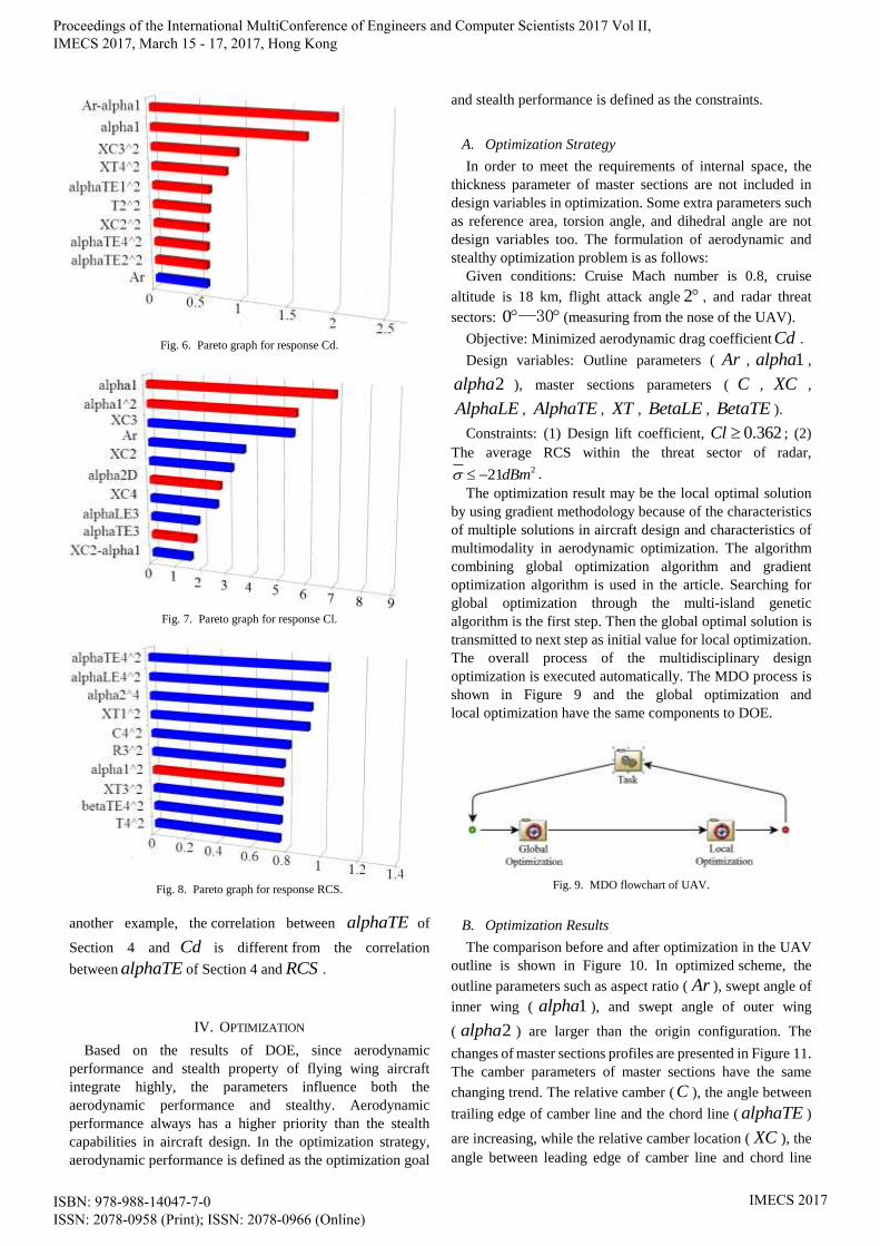
Fig. 6. Pareto graph for response Cd.
Fig. 7. Pareto graph for response Cl.
Fig. 8. Pareto graph for response RCS.
another example, the correlation between alphaTE of
Section 4 and Cd is different from the correlation
between alphaTE of Section 4 and RCS .
IV. OPTIMIZATION
Based on the results of DOE, since aerodynamic
performance and stealth property of flying wing aircraft
integrate highly, the parameters influence both the
aerodynamic performance and stealthy. Aerodynamic
performance always has a higher priority than the stealth
capabilities in aircraft design. In the optimization strategy,
aerodynamic performance is defined as the optimization goal
and stealth performance is defined as the constraints.
A. Optimization Strategy
In order to meet the requirements of internal space, the
thickness parameter of master sections are not included in
design variables in optimization. Some extra parameters such
as reference area, torsion angle, and dihedral angle are not
design variables too. The formulation of aerodynamic and
stealthy optimization problem is as follows:
Given conditions: Cruise Mach number is 0.8, cruise
altitude is 18 km, flight attack angle 2 , and radar threat
sectors: 0 —30 (measuring from the nose of the UAV).
Objective: Minimized aerodynamic drag coefficient Cd .
Design variables: Outline parameters ( Ar , 1alpha ,
2alpha ), master sections parameters ( C , XC ,
AlphaLE , AlphaTE , XT , BetaLE , BetaTE ).
Constraints: (1) Design lift coefficient, 0.362Cl ; (2)
The average RCS within the threat sector of radar, 221dBm .
The optimization result may be the local optimal solution
by using gradient methodology because of the characteristics
of multiple solutions in aircraft design and characteristics of
multimodality in aerodynamic optimization. The algorithm
combining global optimization algorithm and gradient
optimization algorithm is used in the article. Searching for
global optimization through the multi-island genetic
algorithm is the first step. Then the global optimal solution is
transmitted to next step as initial value for local optimization.
The overall process of the multidisciplinary design
optimization is executed automatically. The MDO process is
shown in Figure 9 and the global optimization and
local optimization have the same components to DOE.
Fig. 9. MDO flowchart of UAV.
B. Optimization Results
The comparison before and after optimization in the UAV
outline is shown in Figure 10. In optimized scheme, the
outline parameters such as aspect ratio ( Ar ), swept angle of
inner wing ( 1alpha ), and swept angle of outer wing
( 2alpha ) are larger than the origin configuration. The
changes of master sections profiles are presented in Figure 11.
The camber parameters of master sections have the same
changing trend. The relative camber ( C ), the angle between
trailing edge of camber line and the chord line ( alphaTE )
are increasing, while the relative camber location ( XC ), the
angle between leading edge of camber line and chord line
Proceedings of the International MultiConference of Engineers and Computer Scientists 2017 Vol II, IMECS 2017, March 15 - 17, 2017, Hong Kong
ISBN: 978-988-14047-7-0 ISSN: 2078-0958 (Print); ISSN: 2078-0966 (Online)
IMECS 2017
( alphaLE ) are decreasing. In thickness parameters, relative
thickness location parameters ( XT ) are all larger, and other
thickness parameters have the different tendency.
Fig. 10. Comparison of the aircraft outline between initial and optimized.
(a) Section 1
(b) Section 2
(c) Section 3
(d) Section 4
Fig. 11. Profiles comparison of master sections.
The comparison of aerodynamic performances of flying
wing aircraft before and after optimization is shown in Figure
12 and Figure 13. The slope of lift curve has no change in
optimized configuration, and zero-lift angle of attack is
reducing slightly. The friction drag coefficient after the
optimization is lower than initial scheme in the range of
calculated angles of attack. The RCS distribution is displayed
in Figure 14. The average RCS within the threat sector of
radar is lower and a peak is missing in the distribution map
after optimization.
Fig. 12. Drag coefficient comparison of UAV.
Fig. 13. Lift coefficient comparison of UAV.
Proceedings of the International MultiConference of Engineers and Computer Scientists 2017 Vol II, IMECS 2017, March 15 - 17, 2017, Hong Kong
ISBN: 978-988-14047-7-0 ISSN: 2078-0958 (Print); ISSN: 2078-0966 (Online)
IMECS 2017
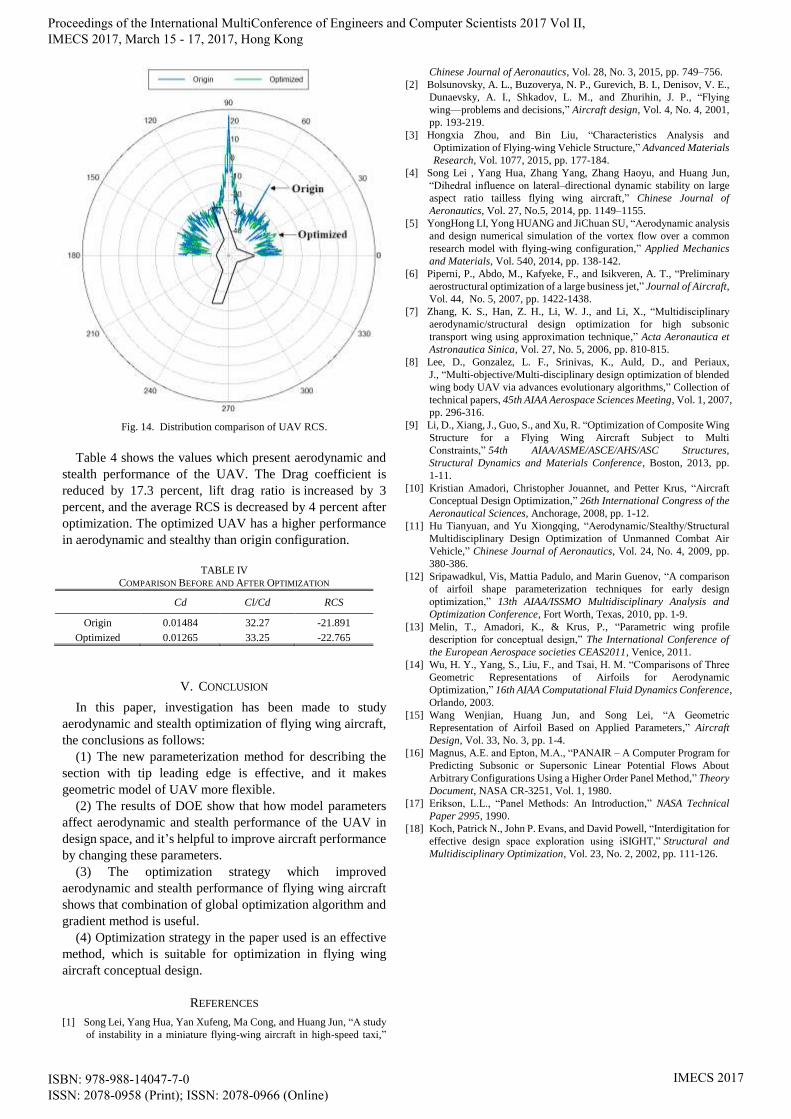
Fig. 14. Distribution comparison of UAV RCS.
Table 4 shows the values which present aerodynamic and
stealth performance of the UAV. The Drag coefficient is
reduced by 17.3 percent, lift drag ratio is increased by 3
percent, and the average RCS is decreased by 4 percent after
optimization. The optimized UAV has a higher performance
in aerodynamic and stealthy than origin configuration.
TABLE IV
COMPARISON BEFORE AND AFTER OPTIMIZATION
Cd Cl/Cd RCS
Origin 0.01484 32.27 -21.891
Optimized 0.01265 33.25 -22.765
V. CONCLUSION
In this paper, investigation has been made to study
aerodynamic and stealth optimization of flying wing aircraft,
the conclusions as follows:
(1) The new parameterization method for describing the
section with tip leading edge is effective, and it makes
geometric model of UAV more flexible.
(2) The results of DOE show that how model parameters
affect aerodynamic and stealth performance of the UAV in
design space, and it’s helpful to improve aircraft performance
by changing these parameters.
(3) The optimization strategy which improved
aerodynamic and stealth performance of flying wing aircraft
shows that combination of global optimization algorithm and
gradient method is useful.
(4) Optimization strategy in the paper used is an effective
method, which is suitable for optimization in flying wing
aircraft conceptual design.
REFERENCES
[1] Song Lei, Yang Hua, Yan Xufeng, Ma Cong, and Huang Jun, “A study
of instability in a miniature flying-wing aircraft in high-speed taxi,”
Chinese Journal of Aeronautics, Vol. 28, No. 3, 2015, pp. 749–756.
[2] Bolsunovsky, A. L., Buzoverya, N. P., Gurevich, B. I., Denisov, V. E.,
Dunaevsky, A. I., Shkadov, L. M., and Zhurihin, J. P., “Flying
wing—problems and decisions,” Aircraft design, Vol. 4, No. 4, 2001,
pp. 193-219.
[3] Hongxia Zhou, and Bin Liu, “Characteristics Analysis and
Optimization of Flying-wing Vehicle Structure,” Advanced Materials
Research, Vol. 1077, 2015, pp. 177-184.
[4] Song Lei , Yang Hua, Zhang Yang, Zhang Haoyu, and Huang Jun,
“Dihedral influence on lateral–directional dynamic stability on large
aspect ratio tailless flying wing aircraft,” Chinese Journal of
Aeronautics, Vol. 27, No.5, 2014, pp. 1149–1155.
[5] YongHong LI, Yong HUANG and JiChuan SU, “Aerodynamic analysis
and design numerical simulation of the vortex flow over a common
research model with flying-wing configuration,” Applied Mechanics
and Materials, Vol. 540, 2014, pp. 138-142.
[6] Piperni, P., Abdo, M., Kafyeke, F., and Isikveren, A. T., “Preliminary
aerostructural optimization of a large business jet,” Journal of Aircraft,
Vol. 44, No. 5, 2007, pp. 1422-1438.
[7] Zhang, K. S., Han, Z. H., Li, W. J., and Li, X., “Multidisciplinary
aerodynamic/structural design optimization for high subsonic
transport wing using approximation technique,” Acta Aeronautica et
Astronautica Sinica, Vol. 27, No. 5, 2006, pp. 810-815.
[8] Lee, D., Gonzalez, L. F., Srinivas, K., Auld, D., and Periaux,
J., “Multi-objective/Multi-disciplinary design optimization of blended
wing body UAV via advances evolutionary algorithms,” Collection of
technical papers, 45th AIAA Aerospace Sciences Meeting, Vol. 1, 2007,
pp. 296-316.
[9] Li, D., Xiang, J., Guo, S., and Xu, R. “Optimization of Composite Wing
Structure for a Flying Wing Aircraft Subject to Multi
Constraints,” 54th AIAA/ASME/ASCE/AHS/ASC Structures,
Structural Dynamics and Materials Conference, Boston, 2013, pp.
1-11.
[10] Kristian Amadori, Christopher Jouannet, and Petter Krus, “Aircraft
Conceptual Design Optimization,” 26th International Congress of the
Aeronautical Sciences, Anchorage, 2008, pp. 1-12.
[11] Hu Tianyuan, and Yu Xiongqing, “Aerodynamic/Stealthy/Structural
Multidisciplinary Design Optimization of Unmanned Combat Air
Vehicle,” Chinese Journal of Aeronautics, Vol. 24, No. 4, 2009, pp.
380-386.
[12] Sripawadkul, Vis, Mattia Padulo, and Marin Guenov, “A comparison
of airfoil shape parameterization techniques for early design
optimization,” 13th AIAA/ISSMO Multidisciplinary Analysis and
Optimization Conference, Fort Worth, Texas, 2010, pp. 1-9.
[13] Melin, T., Amadori, K., & Krus, P., “Parametric wing profile
description for conceptual design,” The International Conference of
the European Aerospace societies CEAS2011, Venice, 2011.
[14] Wu, H. Y., Yang, S., Liu, F., and Tsai, H. M. “Comparisons of Three
Geometric Representations of Airfoils for Aerodynamic
Optimization,” 16th AIAA Computational Fluid Dynamics Conference,
Orlando, 2003.
[15] Wang Wenjian, Huang Jun, and Song Lei, “A Geometric
Representation of Airfoil Based on Applied Parameters,” Aircraft
Design, Vol. 33, No. 3, pp. 1-4.
[16] Magnus, A.E. and Epton, M.A., “PANAIR – A Computer Program for
Predicting Subsonic or Supersonic Linear Potential Flows About
Arbitrary Configurations Using a Higher Order Panel Method,” Theory
Document, NASA CR-3251, Vol. 1, 1980.
[17] Erikson, L.L., “Panel Methods: An Introduction,” NASA Technical
Paper 2995, 1990.
[18] Koch, Patrick N., John P. Evans, and David Powell, “Interdigitation for
effective design space exploration using iSIGHT,” Structural and
Multidisciplinary Optimization, Vol. 23, No. 2, 2002, pp. 111-126.
Proceedings of the International MultiConference of Engineers and Computer Scientists 2017 Vol II, IMECS 2017, March 15 - 17, 2017, Hong Kong
ISBN: 978-988-14047-7-0 ISSN: 2078-0958 (Print); ISSN: 2078-0966 (Online)
IMECS 2017