Embed Size (px)
Citation preview
THE EXPERT IN LEVEL AND FLOW
FLOW
Integral Orifice Assembly
Measuring Section for Small Flow Measurement
Technical Information
11/2016

Intra-Automation Technical Information Integral Orifice Assembly
- 1 -
Intra-Automation Technical Information
11/2016
Technical data subject to be changed.
For Comments regardingKommentare oder Anregungen bezüglich dieser Broschüre wenden Sie sich bitte an::
Integral Orifice Assembly Technical Information Intra-Automation
- 2 -
Intregral Orifice Assembly
Measuring Section for Small Flow Measurement
List of Contents: Chapt. Title Page
1 Features 3
2 Description of the Orifice Calculation 3
3 Technical Data 3
4 Flow Calculation 4
5 Order Code 4
6 Dimensions 5
Intra-Automation Technical Information Integral Orifice Assembly
- 3 -
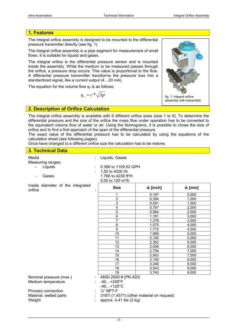
1. Features
The integral orifice assembly is designed to be mounted to the differential pressure transmitter directly (see fig. 1).
The integral orifice assembly is a pipe segment for measurement of small flows. It is suitable for liquids and gases.
The integral orifice is the differential pressure sensor and is mounted inside the assembly. While the medium to be measured passes through the orifice, a pressure drop occurs. This value is proportional to the flow. A differential pressure transmitter transforms the pressure loss into a standardized signal, like a current output (4…20 mA).
The equation for the volume flow qv is as follows:
pcqv ∆= *
2. Description of Orifice Calculation
The integral orifice assembly is available with 6 different orifice sizes (size 1 to 6). To determine the differential pressure and the size of the orifice the mass flow under operation has to be converted to the equivalent volume flow of water or air. Using the Nomograms, it is possible to chose the size of orifice and to find a first approach of the span of the differential pressure. The exact value of the differential pressure has to be calculated by using the equations of the calculation sheet (see following pages). Once have changed to a different orifice size the calculation has to be redone.
3. Technical Data
Media : Liquids, Gases Measuring ranges:
- Liquids
- Gases
: :
0.396 to 1109.52 GPH 1,50 to 4200 l/h 1.766 to 4238 ft³/h 0,05 to 120 m³/h
Inside diameter of the integrated orifice
: Size di [inch] di [mm]
1 0,197 0,500 2 0,394 1,000 3 0,591 1,500 4 0,787 2,000 5 0,984 2,500 6 1,181 3,000 7 1,378 3,500 8 1,575 4,000 9 1,772 4,500 10 1,969 5,000 11 2,165 5,500 12 2,362 6,000 13 2,559 6,500 14 2,756 7,000 15 2,953 7,500 16 3,150 8,000 17 3,346 8,500 18 3,543 9,000 19 3,740 9,500 Nominal pressure (max.) : ANSI 2500 # (PN 420) Medium temperature : -40…+248°F
-40…+120°C Process connection : ½“ NPT-F Material, wetted parts : 316Ti (1.4571) (other material on request) Weight : approx. 4.41 lbs (2 kg)
fig. 1: integral orifice assembly with transmitter
Integral Orifice Assembly Technical Information Intra-Automation
- 4 -
4. Flow Calculation
Flow Calculation with Conval®-Software and subsequent water calibration.
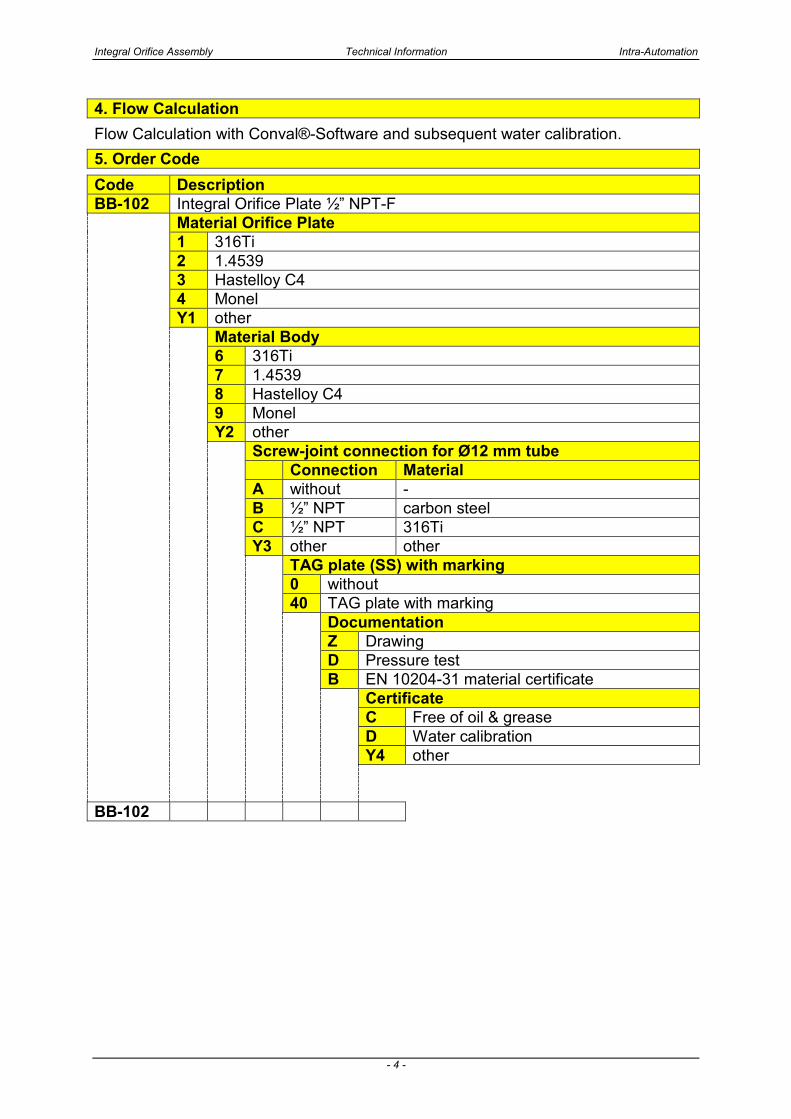
5. Order Code
Code Description BB-102 Integral Orifice Plate ½” NPT-F Material Orifice Plate 1 316Ti 2 1.4539 3 Hastelloy C4 4 Monel Y1 other Material Body 6 316Ti 7 1.4539 8 Hastelloy C4 9 Monel Y2 other Screw-joint connection for Ø12 mm tube Connection Material A without - B ½” NPT carbon steel C ½” NPT 316Ti Y3 other other TAG plate (SS) with marking 0 without 40 TAG plate with marking Documentation Z Drawing D Pressure test B EN 10204-31 material certificate Certificate C Free of oil & grease D Water calibration Y4 other
BB-102
Intra-Automation Technical Information Integral Orifice Assembly
- 5 -
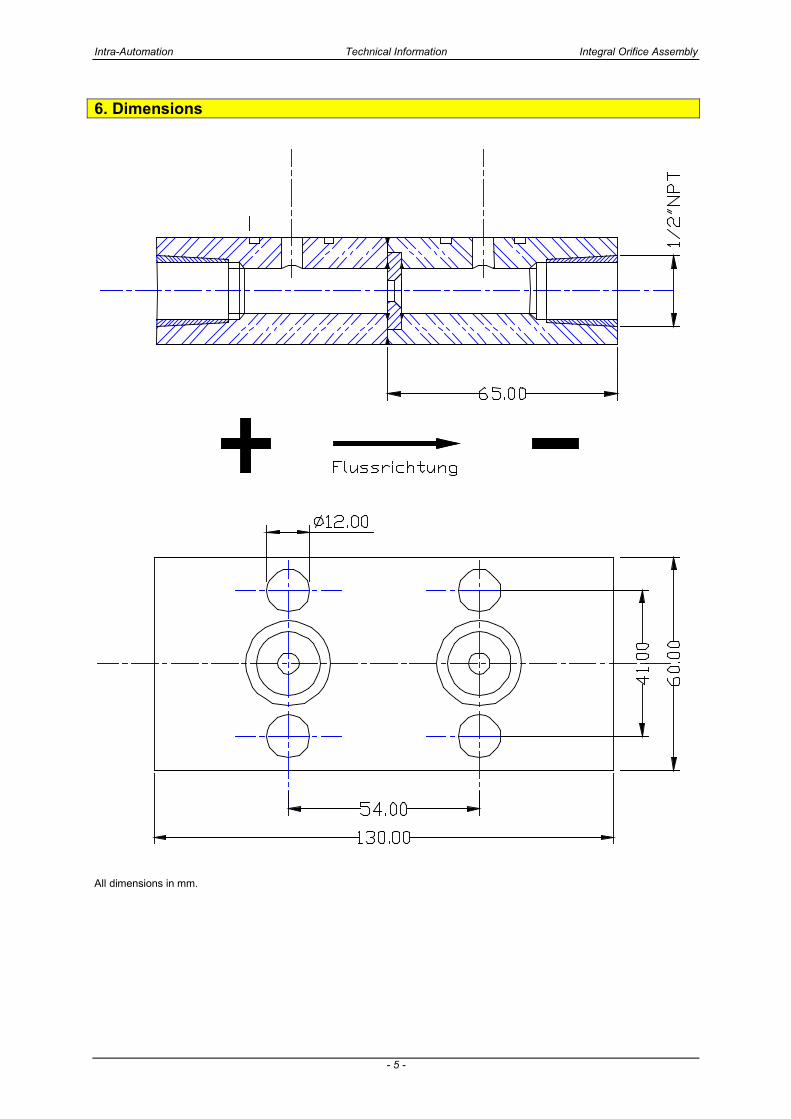
6. Dimensions
All dimensions in mm.
Integral Orifice Assembly Technical Information Intra-Automation
- 6 -
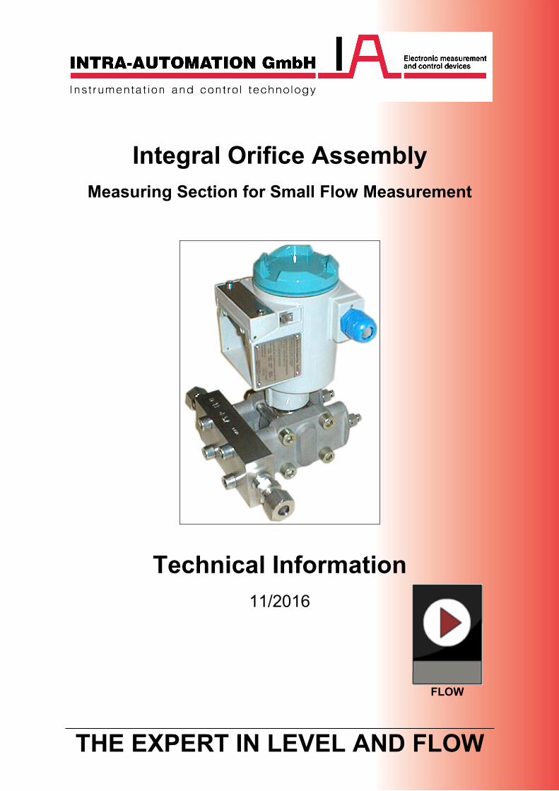
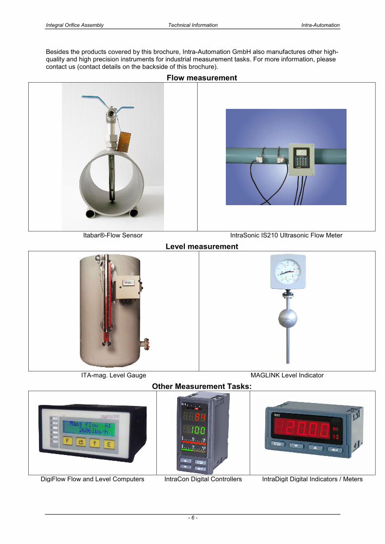
Besides the products covered by this brochure, Intra-Automation GmbH also manufactures other high-quality and high precision instruments for industrial measurement tasks. For more information, please contact us (contact details on the backside of this brochure).
Flow measurement
Itabar®-Flow Sensor IntraSonic IS210 Ultrasonic Flow Meter
Level measurement
ITA-mag. Level Gauge MAGLINK Level Indicator
Other Measurement Tasks:
DigiFlow Flow and Level Computers IntraCon Digital Controllers IntraDigit Digital Indicators / Meters
Intra-Automation Technical Information Integral Orifice Assembly
- 7 -
International Headquarters: Sales Office for the BENELUX: Intra-Automation GmbH B.V. Intra-Automation HTP Otto-Hahn-Str. 20 PO Box 10 41515 Grevenbroich 4730 AA Oudenbosch GERMANY THE NETHERLANDS +49 – (0) 21 81 / 7 56 65-0 +31 – (0)165 – 32 22 01 +49 – (0) 21 81 / 6 44 92 +31 – (0)165 – 32 29 70 [email protected] [email protected]
www.intra-automation.com