Embed Size (px)
Citation preview

Click to edit Master title styleIntegral Bridges and the
Modeling of Soil-Structure
Interaction
Julian Moses, Principal Engineer, LUSAS

Introduction
2

Introduction
3
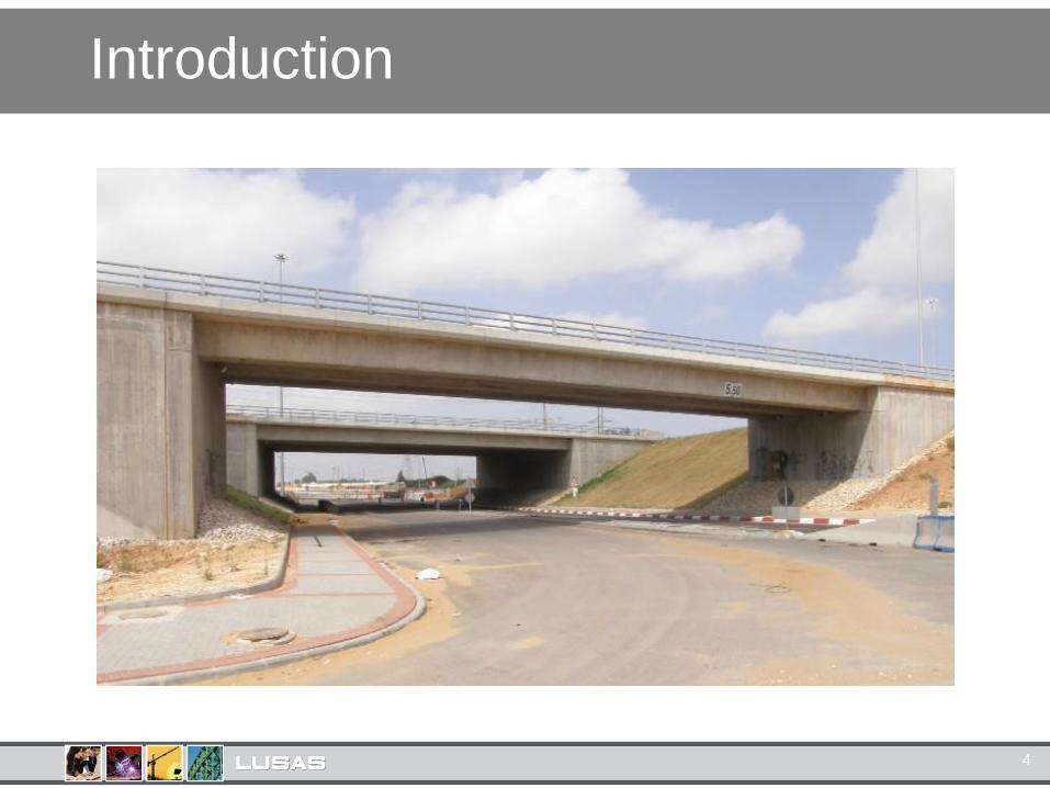
Introduction
4

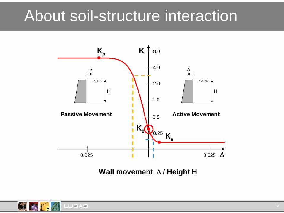
About soil-structure interaction
5
About soil-structure interaction
6
Active Movement
0.0250.025
Passive Movement
Wall movement / Height H
1.0
2.0
4.0
8.0
0.5
0.25
K
H
H
Kp
K0
Ka

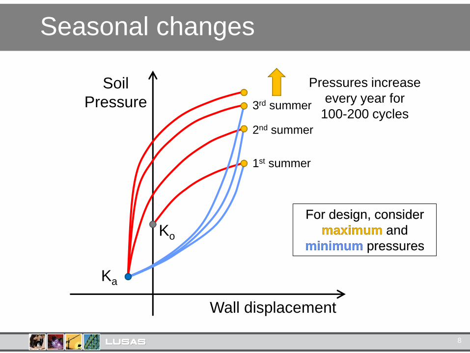
Seasonal changes
7
Seasonal changes
8
Ko
Soil
Pressure
Ka
Pressures increase
every year for
100-200 cycles
Wall displacement
1st summer
2nd summer
3rd summer
For design, consider
maximum and
minimum pressures

Analysis methods
1. Limiting equilibrium approach
2. Soil-structure interaction (continuum)
3. Soil-structure interaction (springs)
9
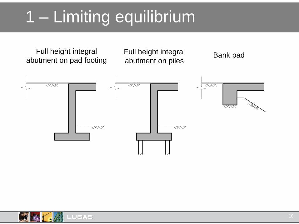
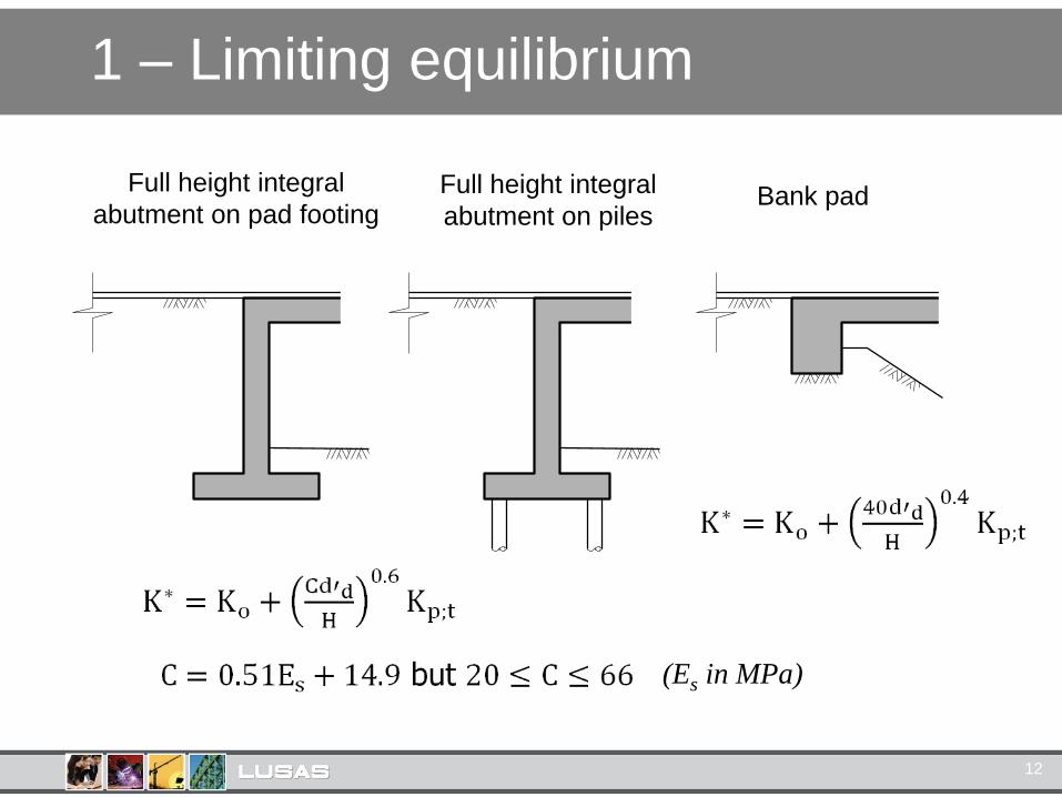
1 – Limiting equilibrium
10
Full height integral
abutment on pad footingFull height integral
abutment on pilesBank pad

1 – Limiting equilibrium
11
1 – Limiting equilibrium
12
Full height integral
abutment on pad footingFull height integral
abutment on pilesBank pad
(Es in MPa)

1 – Limiting equilibrium
14
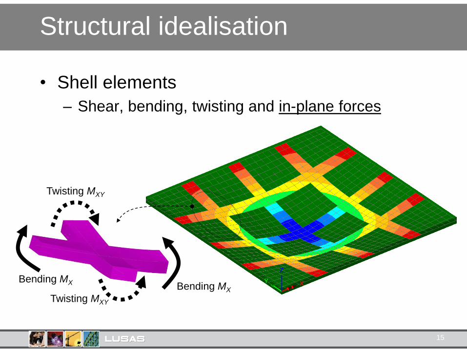
Structural idealisation
• Shell elements
– Shear, bending, twisting and in-plane forces
Twisting MXY
Twisting MXY
Bending MX
Bending MX
15
XY
Z
XY
Z
XY
Z
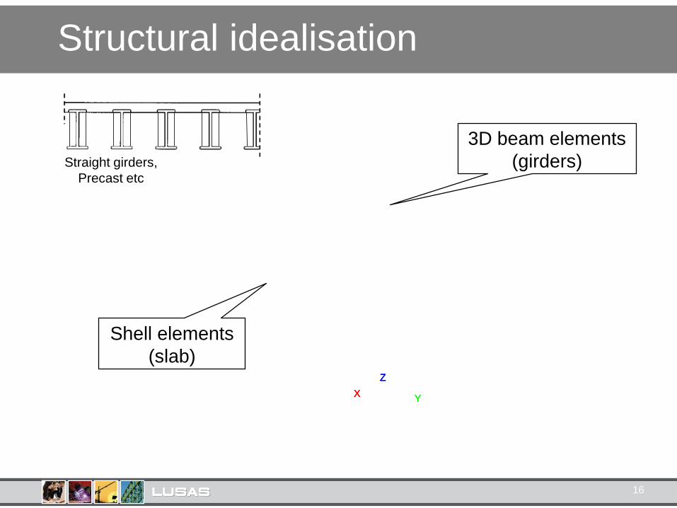
Structural idealisation
16
3D beam elements
(girders)
Shell elements
(slab)
Straight girders,
Precast etc

X
Y
Z
Structural idealisation
17
3D beam elements
(flanges & stiffeners)
3D beam elements
(bracing)
Shell elements
(slab)
Shell elements
(web)
Skew or curved etc

X
Y
Z
Structural idealisation
18

Grid models
“The conventional 2D-grid models used in current practice
• Substantially underestimate the girder torsional
stiffnesses in I-girder bridges
• Substantially misrepresent the cross-frame responses
• Do not address the calculation of girder flange lateral
bending in skewed I-girder bridges” Section 2.9
19

Grid models
20
“...difficulties arise when in-plane effects are
considered... the real problem is the occurrence of
local in-plane distortions of the grillage members...
which are clearly inconsistent with the behaviour of the
bridge deck.” Section 7.5

1 – Limiting equilibrium
21
Shell elements
(slabs)

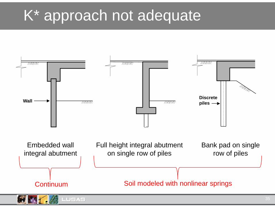
K* approach not adequate
22
Full height integral abutment
on single row of piles
Bank pad on single
row of piles
Discrete
piles
Embedded wall
integral abutment
Wall
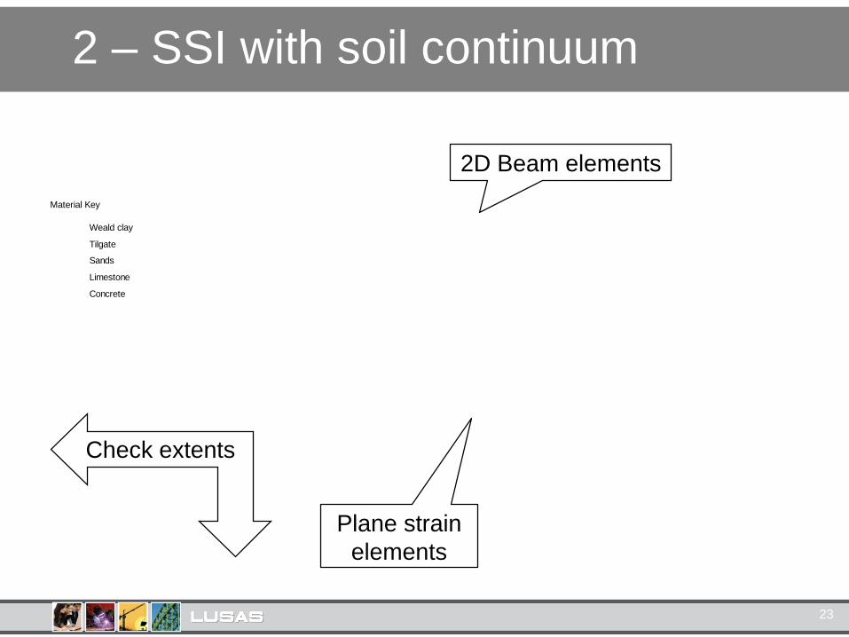
2 – SSI with soil continuum
23
Material Key
Concrete
Limestone
Sands
Tilgate
Weald clay
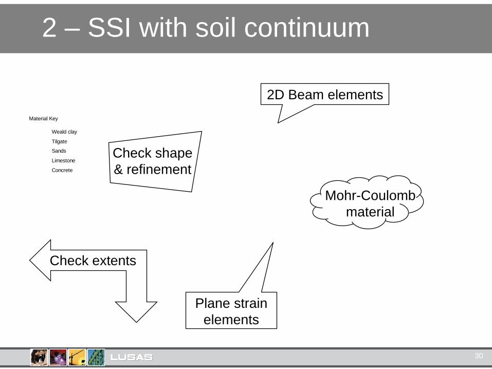
Plane strain
elements
2D Beam elements
Check extents

2 – SSI with soil continuum
Mesh checks
1. Width & depth of soil block
2. Element shapes and aspect ratios
3. Mesh refinement
4. Element formulation – quadratic better
24
Avoid angles <30°1:1 ideal
1:3 max (areas of interest)
1:10 max (remote)
Need automatic re-meshing

2 – SSI with soil continuum
25
Material Key
Concrete
Limestone
Sands
Tilgate
Weald clay
Check shape
& refinement
Plane strain
elements
Check extents
2D Beam elements

2 – SSI with soil continuum
26
10
m
10m
Mohr Coulomb yield surface
3
2
1
1
2
3

2 – SSI with soil continuum
27
2 – SSI with soil continuum
30
Material Key
Concrete
Limestone
Sands
Tilgate
Weald clay
Check shape
& refinement
Plane strain
elements
Check extents
Mohr-Coulomb
material
2D Beam elements
2 – SSI with soil continuum
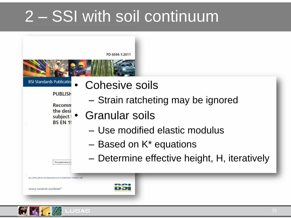
• Cohesive soils
– Strain ratcheting may be ignored
• Granular soils
– Use modified elastic modulus
– Based on K* equations
– Determine effective height, H, iteratively
31

2 – SSI with soil continuum
32
Material Key
Concrete
Limestone
Sands
Tilgate
Weald clay
Mohr-Coulomb
material
Modified elastic
modulus*Check shape
& refinement
Plane strain
elements
Check extents
2D Beam elements

2 – SSI with soil continuum
• Interface between soil and structure
– Joint elements
– Contact slidelines
– Elasto-plastic interface materials
• Back of wall friction angle, δ
– Maximum δ=φ’
– Smooth δ=0
– Suggested δ=φ'/2
33

2 – SSI with soil continuum
34
Material Key
Concrete
Limestone
Sands
Tilgate
Weald clay
Mohr-Coulomb
material
Modified elastic
modulus*Check shape
& refinement
Plane strain
elements
Check extents
Frictional interface
δ=φ'/2 2D Beam elements
K* approach not adequate
35
Full height integral abutment
on single row of piles
Bank pad on single
row of piles
Discrete
piles
Embedded wall
integral abutment
Wall
Continuum Soil modeled with nonlinear springs
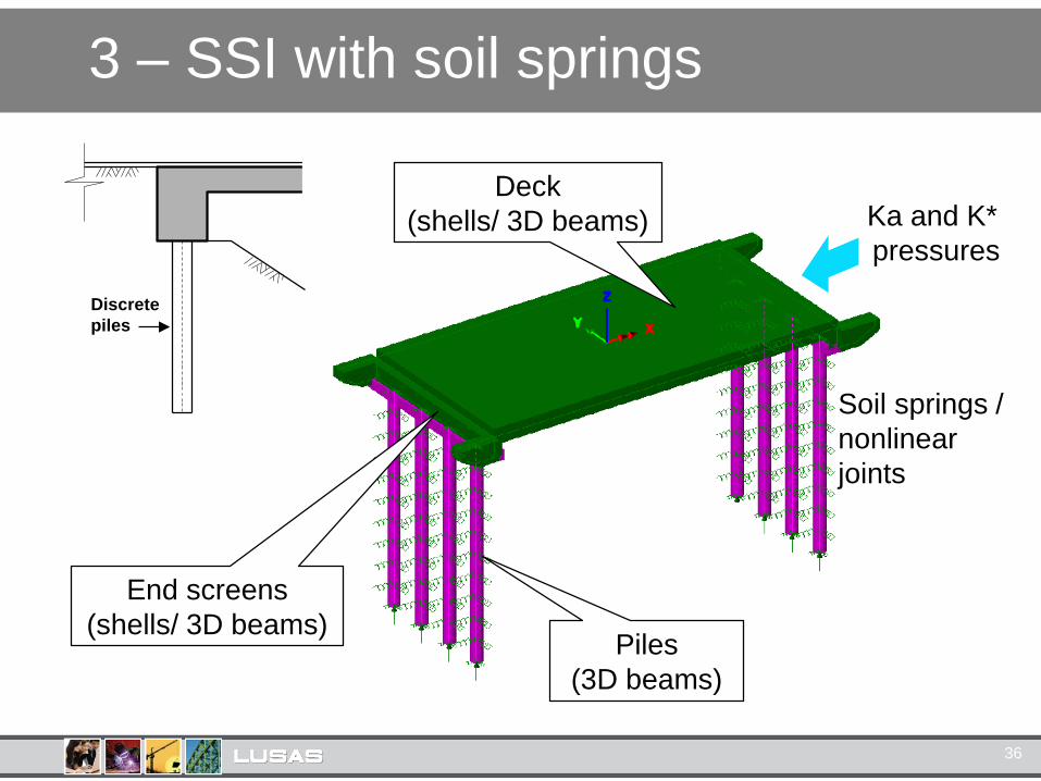
3 – SSI with soil springs
36
Deck
(shells/ 3D beams)
End screens
(shells/ 3D beams)Piles
(3D beams)
Ka and K*
pressures
Soil springs /
nonlinear
joints
Discrete
piles

3 – SSI with soil springs
37
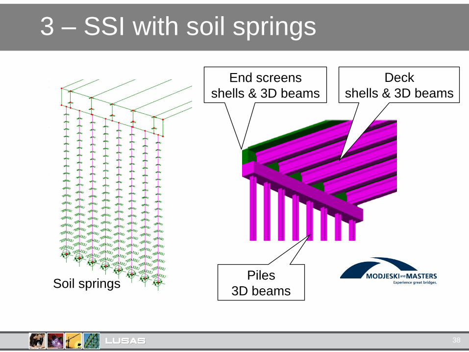
3 – SSI with soil springs
Deck
shells & 3D beams
End screens
shells & 3D beams
Piles
3D beamsSoil springs
38
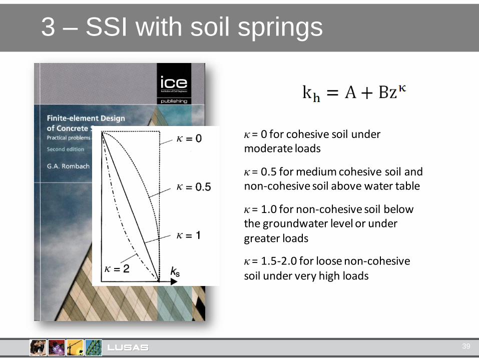
3 – SSI with soil springs
39
κ = 0 for cohesive soil under moderate loads
κ = 0.5 for medium cohesive soil and non-cohesive soil above water table
κ = 1.0 for non-cohesive soil below the groundwater level or under greater loads
κ = 1.5-2.0 for loose non-cohesive soil under very high loads
κ
κ
κ
κ

3 – SSI with soil springs
40
Stiffer,
stronger
Softer,
weaker
Discrete
piles

3 – SSI with soil springs
41
Lateral pressure
kh
Horizontal deflection
'a
'p
Active Movement
Passive Movement
'0

3 – SSI with soil springs
42

Software requirements
• Structural elements (beams, shells)
• Geotechnical elements (joints, springs,
continuum)
• Automatic remeshing
• Nonlinear materials (e.g. Mohr Coulomb)
• Easy way to vary properties with depth
43

Summary
44
Soil continuum
Soil Springs UK Guidance: PD6694-1