Embed Size (px)
Citation preview

A
larm
Con
trol P
anel
Firm
war
e V
ersi
on 1
.07
GDAŃSK
integra-wrl_i_en 08/09
INSTALLER MANUAL
1471

WARNINGS For safety reasons, the security alarm system should only be installed by qualified personnel. Before you begin the installation, read carefully this manual so as to avoid the risk of electric shock. Any electric connections may only be made in deenergized state, with power supply disconnected. The security alarm system may comprise hazardous equipment, therefore it is important that its components be stored so as to prevent unauthorized access. Never make any unauthorized construction modifications or repairs. This requirement applies, in particular, to replacement of assemblies and components. CAUTION! It is not allowed to connect a fully discharged battery (with voltage across unloaded terminals less than 11 V) to the alarm panel. If the battery is fully discharged or it has never been in use, precharge it by means of a suitable charger, to avoid the risk of equipment damage. The batteries applied for the security systems contain lead. Never throw away the batteries when used up, but dispose them of as required by the existing regulations (European Directives 91/157/EEC and 93/86/EEC).
DECLARATION OF CONFORMITY 1471
Products: INTEGRA 128-WRL control panel
Manufacturer: SATEL spółka z o.o. ul. Schuberta 79 80-172 Gdańsk, POLSKA tel. (+48 58) 320-94-00 fax. (+48 58) 320-94-01
Product description: INTEGRA 128-WRL control panel, provided with ABAX wireless communication system and GSM/GPRS communicator, designed for use in burglary and panic alarm systems. These products are in conformity with the following EU Directives: R&TTE 1999/5/EC The product meets the requirements of harmonized standards: Art. 3.2 (effective spectrum usage): ETSI EN 300 220-1: v.2.1.1; ETSI EN 300 220-2: v.2.1.2; ETSI EN 301 511 V9.0.2; 3GPP TS 151.010-1 V5.10.0 Art. 3.1b (electromagnetic compatibility): ETSI EN 301 489-1: v.1.6.1.; EN 301 489-3: v.1.4.1; EN 301 489-7: V1.3.1 Art. 3.1a (safety of operation): EN60950-1:2001 Notified body taking part in conformity evaluation: Identification No: 1471 Gdańsk, Polska 2008-11-10 Head of Test Laboratory:
Michał Konarski The list of countries where the INTEGRA 128-WRL has been approved for use – please see the website
www.satel.pl
The SATEL's goal is to continually upgrade the quality of our products, which may result in alterations of their technical specifications and firmware. The current information on the
introduced modifications is available on our website. Please visit us at:
http://www.satel.eu
New functions of the INTEGRA 128-WRL control panels in version 1.07 Zones Option to use resistors of different values in 2EOL configuration. LCD keypad Keypad restart does not cause exit from the service mode. Wireless devices
Support for new wireless devices: – AMD-102 – wireless magnetic contact with input for roller shutter
detector, – ARD-100 – wireless reorientation detector.
Expansion modules
Support for ABAX ACU-100 wireless system controller with firmware version 1.08 and 2.01.
2 INTEGRA 128-WRL SATEL
CONTENTS 1. General description...........................................................................................................3
2. System specifications .......................................................................................................3 2.1 Mainboard..................................................................................................................4 2.2 LCD keypads .............................................................................................................5 2.3 Optional modules.......................................................................................................5
2.3.1 Modules to be connected to keypad bus........................................................................ 5 2.3.2 Modules to be connected to expander bus .................................................................... 5
2.4 Wireless devices........................................................................................................8 3. System installation ............................................................................................................8
3.1 Installation plan..........................................................................................................9 3.2 Estimation of system current consumption ................................................................9 3.3 Cabling ......................................................................................................................9 3.4 Installation of control panel mainboard ......................................................................9 3.5 Connecting keypads and other devices to keypad bus............................................12
3.5.1 Addressing devices connected to keypad bus ............................................................. 14 3.5.1.1 Programming keypad address by means of service function ................................................ 14 3.5.1.2 Programming keypad address without entering service mode .............................................. 15
3.5.2 Numeration of keypad zones ....................................................................................... 15 3.5.3 Keypad RS-232 port..................................................................................................... 16
3.6 Connecting devices to expander bus.......................................................................16 3.6.1 Addressing devices connected to expander bus.......................................................... 18
3.7 Connecting hardwired detectors ..............................................................................19 3.8 Connecting sirens ....................................................................................................22 3.9 Connecting voice synthesizer ..................................................................................24 3.10 Connecting printer ...................................................................................................24 3.11 Connecting power supply ........................................................................................25
3.11.1 Power supply connection procedure............................................................................ 26 3.12 Starting control panel...............................................................................................26 3.13 Starting GSM telephone ..........................................................................................27 3.14 Installation of wireless devices.................................................................................28
3.14.1 Adding new wireless devices ....................................................................................... 30 3.14.1.1 DLOADX program .................................................................................................................... 30 3.14.1.2 LCD keypad............................................................................................................................ 30
3.14.2 Removing wireless devices.......................................................................................... 31 3.14.2.1 DLOADX program .................................................................................................................... 31 3.14.2.2 LCD keypad............................................................................................................................ 31
4. Compliance with CLC/TS 50131-3 requirements............................................................32
5. Technical data ................................................................................................................32 5.1 Control panel mainboard .........................................................................................32 5.2 INT-KLCD-GR / INT-KLCD-BL keypad ....................................................................32 5.3 INT-KLCDR-GR / INT-KLCDR-BL keypad...............................................................33 5.4 INT-KLCDL-GR / INT-KLCDL-BL keypad ................................................................33 5.5 INT-KLCDS-GR / INT-KLCDS-BL keypad ...............................................................33 5.6 INT-KLCDK-GR keypad...........................................................................................33
6. History of the manual updates ........................................................................................34
SATEL Installer Manual 3
1. GENERAL DESCRIPTION • Dedicated modern microprocessor-based construction for protection of medium-to-big-size
facilities, with built-in GSM/GPRS industrial telephone and support for hardwired and wireless devices.
• Two-way encrypted communication with ABAX system wireless devices on 868.0 MHz - 868.6 MHz frequency band. The acknowledgement feature provided for all sent transmissions, to ensure that the information gets through and to check devices for their presence in the system. Parameter configuration and testing of the wireless devices performed by radio, without removal of their cover.
• Firmware of the alarm control panel is stored in FLASH type non-volatile memory, so it can be easily updated with no need for dismounting of the panel. It only requires connection of the panel to the computer via RS-232 port and starting of the procedure of firmware replacement.
• Saving the control panel settings to FLASH memory. These data will be retained even if the RAM memory backup battery is disconnected.
• Execution of non-standard control functions, owing to the possibility of programming complex logical operations on the outputs.
• System expansion by means of expansion modules. They not only increase the number of available zones and outputs (both hardwired and wireless), but enhance the system with new functional capabilities.
2. SYSTEM SPECIFICATIONS • Capability to create up to 8 objects (subsystems). • Optional subdivision of the system into 32 partitions (partition = group of zones). • Partition status (armed/disarmed) can be controlled by user, timer or system zone.
Partition status can also be made dependent on the status of other partitions. • Up to 128 programmable zones (hardwired and wireless) with support for NO, NC, EOL
and 2EOL configurations. One of several dozens of reaction types can be assigned for each zone.
• Optional control of the zone status by using output, with no need for making physical connection, which enables virtual zones and outputs to be used in the system.
• Up to 128 programmable outputs. One of over a hundred functions can be chosen for execution.
• Up to 8 keypads or other devices can be connected to the keypad bus (CA-64 PTSA, ETHM-1, INT-RS).
• Up to 32 expansion modules can be connected to the expander bus. • 240 codes (passwords) for system users including a dozen of code types with the
possibility to define the system access authority level. Additionally, 8 administrator codes and a service code are available.
• 64 system timers defined by the service, to enable armed mode control based on time parameters. Additionally, partition timers (1 per each partition), programmed by authorized users.
• Editable names of users and most of the security system components (partitions, zones, outputs, modules, timers, etc.) to facilitate managements of the system.
• Variety of means for control panel programming: – LCD keypad, – computer with DLOADX program installed (locally through RS-232 port or remotely via
telephone links, and optionally – with ETHM-1 module connected – also through Ethernet network, using TCP/IP protocol),
4 INTEGRA 128-WRL SATEL
– web browser (optionally, with ETHM-1 module connected), – mobile phone with MobileKPD application installed (optionally, with ETHM-1 module
connected), – palmtop (PDA or MDA) with suitable application installed (optionally, with ETHM-1
module connected). • Variety of means for security system control:
– LCD keypad, – key fob (optionally, with INT-RX module installed), – computer with DLOADX or GUARDX program installed, – SMS message, – web browser (optionally, with ETHM-1 module connected), – mobile phone with MobileKPD application installed (optionally, with ETHM-1 module
connected), – palmtop (PDA or MDA) with suitable application installed (optionally, with ETHM-1
module connected). • Possibility to control individual partitions by means of partition keypads and proximity card
readers or DALLAS chips. • Execution of the access control function by means of partition keypads, code locks and
readers of proximity cards / DALLAS chips. Door status control by modules does not reduce the number of control panel supervision zones.
• Automatic diagnostics of the system essential components. • Reporting events to two monitoring stations (four telephone numbers) by means of:
– GSM voice channel, – GPRS, – SMS messages, – Ethernet network and TCP/IP protocol (optionally, with ETHM-1 module connected).
• Sending events to monitoring station in several formats, including Contact ID and SIA. • Sending messages about system events to 16 telephone numbers in the form of:
– voice messages played back by speech synthesizer (up to 16), – SMS text messages (up to 64), – PAGER text messages (up to 64).
• Call answering function, which enables checking the partition status by means of telephone keys (DTMF) or SMS messages.
• Event log, covering not only the monitored events, but also user access, functions used, etc.
• Advanced function of real-time event printout with optional selection of events. Event descriptions meet the Contact ID standard. Also, the names of zones, modules and users are printed as they are defined in the system.
2.1 MAINBOARD • 8 individually programmable hardwired zones with additional support for vibration
detectors and roller shutter motion detectors. • Programmable resistor values for hardwired zones in EOL and 2EOL configuration. • 8 individually programmable hardwired outputs:
– 2 high-current outputs, current-carrying capacity 2 A, with polymer fuses, – 6 low-current outputs, current-carrying capacity 50 mA, designed for relay control.
• 3 high-current outputs, current-carrying capacity 0.5 A, with polymer fuses, having power supply output functionality.
SATEL Installer Manual 5
• Direct support of up to 48 wireless devices of the ABAX system (up to 48 wireless zones / outputs).
• Communication bus designed for connecting LCD keypads and some additional modules (keypad bus).
• Communication bus designed for connecting additional modules to expand functional capabilities of the mainboard (expander bus).
• Interface for connection of CA-64 SM (or SM-2) voice synthesizer. • Industrial type, three-range GSM phone, designed for operation in 900/1800/1900 MHz
networks, offering the functions of monitoring, messaging, call answering and control, as well as remote programming (GSM or GPRS).
• Internal GSM modem (transmission rate 300 bps or CSD, i.e. 9.6 kb/s). • RS-232 port for operating the security system from a computer (DLOADX installer
program), for printer support and external modem control. • Switching mode power supply, output current 2 A, with short-circuit protection, provided
with battery status monitoring and low battery disconnection circuit. • Visual indication of the status of outputs, battery charging circuit, GSM telephone and
wireless devices communication module. • Electric protection of all hardwired zones and outputs, as well as communication buses.
2.2 LCD KEYPADS Keypads interfacing with the INTEGRA control panels are made with or without a built-in proximity card reader. They have the following features: • Large, easy to read 2 x 16 character display with permanent or temporary backlighting
activated on pressing a key or by any control panel zone. • Keys with backlighting controlled in the same way as the display backlighting. • 2 programmable zones with support for NO, NC, EOL and 2EOL configurations. • Tamper switch for detection of housing opening/pull-off from the mounting surface. • RS-232 port to enable operating the security system from a computer (using GUARDX
administrator/user program).
2.3 OPTIONAL MODULES Optional modules make the INTEGRA 128-WRL based security system flexible enough to be optimally adapted to the specific needs and requirements of the customer.
2.3.1 Modules to be connected to keypad bus CA-64 PTSA. Mimic board. Enables visualization of the state of partitions/zones in the
security system. The INTEGRA 128-WRL control panel supports the mimic boards made in version CA64T v 1.4 and having firmware in version v4.0 or later.
ETHM-1. Ethernet module. Makes it possible to operate the control panel through the Ethernet. INTEGRA 128-WRL control panel supports ETHM-1 modules in version 1.02 or later.
INT-RS. Data converter. Makes it possible to connect a computer with GUARDX program installed, similarly as to LCD keypad, monitor events by using a special external device, and operate the control panel by means of software other than that offered by SATEL.
2.3.2 Modules to be connected to expander bus CA-64 E. Zone expander. Enables system expansion by 8 zones with support for NO, NC,
EOL and 2EOL configurations. The expander with electronics in version 2.1 (or later) and firmware in version 2.0 (or later), where the DIP-switch 8 is set in ON position, will
6 INTEGRA 128-WRL SATEL
be identified by the control panel as CA-64 Ei. Additionally, the CA-64 Ei expander zones offer support for vibration / roller shutter detectors.
CA-64 EPS. Zone expander with power supply. Enables system expansion by 8 zones. Equipped with a 1.2 A built-in switching mode power supply. The expander with electronics in version 2.0 (or later) and firmware in version 2.0 (or later), where the DIP-switch 8 is set in ON position, will be identified by the control panel as CA-64 EPSi. Additionally, the CA-64 EPSi expander zones offer support for vibration / roller shutter detectors.
CA-64 ADR. Addressable zone expander. Enables system expansion by 48 zones. Equipped with a 2.2 A built-in switching mode power supply. The INTEGRA 128-WRL control panel supports the addressable zone expanders with firmware version v1.5 or later.
CA-64 O-OC/CA-64 O-R/CA-64 O-ROC. Outputs expander. Enables system expansion by 8 outputs. Made in three versions with 8 OC type outputs, 8 relay outputs, and 4 relay outputs/4 OC outputs.
INT-ORS. DIN-rail outputs expander. Enables system expansion by 8 relay outputs. The relays can control electrical devices supplied with 230 V AC voltage.
Note: If the sixth DIP-switch in the INT-ORS expander is set in the upper position, the device will be identified by the control panel as the CA-64 O output expander.
CA-64 OPS-OC/CA-64 OPS-R/CA-64 OPS-ROC. Output expander with power supply. Enables expansion of the system by 8 outputs. Made in three versions: 8 OC type outputs, 8 relay outputs and 4 relay outputs/4 OC outputs. Equipped with a 2.2 A built-in switching mode power supply.
INT-IORS. DIN-rail zones/outputs expander. Enables expansion of the system by 8 zones and 8 relay outputs. The relays can control the electrical devices supplied with 230 V AC voltage.
Note: If the sixth DIP-switch in the INT-IORS expander is set in upper position, the device will be identified by the control panel as the CA-64 PP zone/output expander.
CA-64 PP. Zone/Output Expander with Power Supply. Enables expansion of the system by 8 zones and 8 outputs (4 relay and 4 OC type). Equipped with a 2.2 A built-in switching mode power supply.
INT-S-GR / INT-S-BL / INT-SK-GR. Partition Keypad. Controls the armed mode in one partition; can perform the access control functions and operate the electromagnetic door lock.
INT-SCR-BL. Depending on its settings, the device can work as a partition keypad (identified as INT-S in the control panel), a partition keypad with reader (identified as INT-SCR in the control panel) or an entry keypad (identified as INT-ENT in the control panel). If it operates as a partition keypad or a partition keypad with reader, the device can control armed mode in one partition, execute access control functions, and control operation of the electromagnetic door lock. The main task of the entry keypad is activation of the delay for zones with reaction type 3 INTERIOR DELAYED. After expiry of the time programmed in the keypad, unless the system has been disarmed, the interior delayed zones will operate again as the instant ones.
INT-SZ-GR/INT-SZ-BL/INT-SZK-GR. Code lock. Enables execution of the access control functions and operation of the electromagnetic door lock.
CA-64 SR. Expander for proximity card readers. Supports the SATEL made proximity card readers, enabling execution of the access control functions and operation of the electromagnetic door lock. Enables control of the partition status by means of proximity cards.
SATEL Installer Manual 7
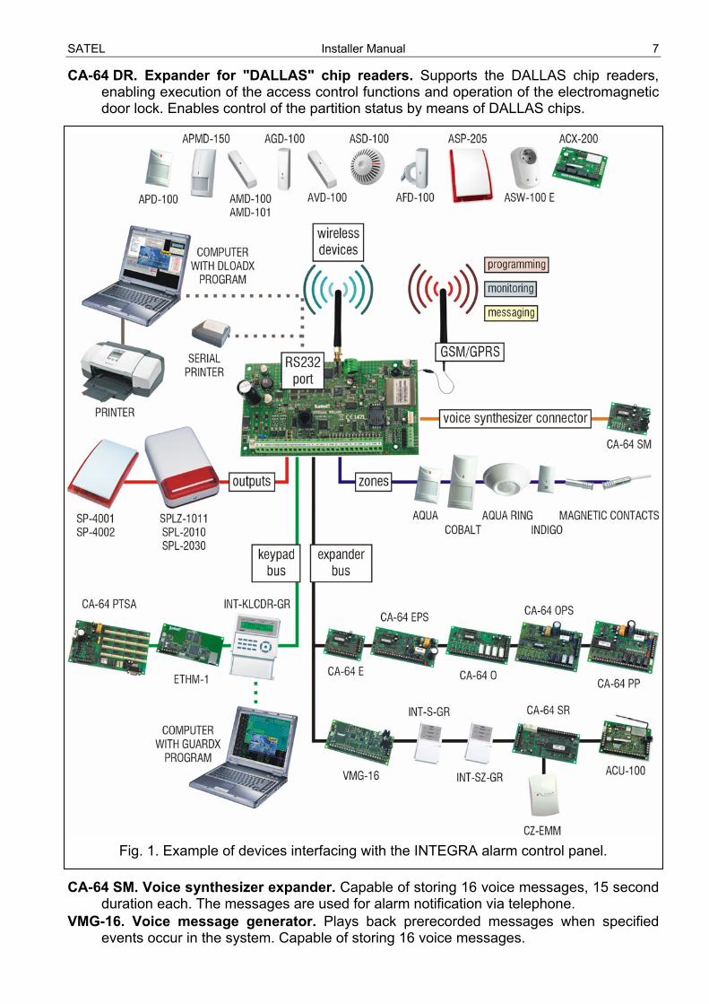
CA-64 DR. Expander for "DALLAS" chip readers. Supports the DALLAS chip readers, enabling execution of the access control functions and operation of the electromagnetic door lock. Enables control of the partition status by means of DALLAS chips.
Fig. 1. Example of devices interfacing with the INTEGRA alarm control panel.
CA-64 SM. Voice synthesizer expander. Capable of storing 16 voice messages, 15 second
duration each. The messages are used for alarm notification via telephone. VMG-16. Voice message generator. Plays back prerecorded messages when specified
events occur in the system. Capable of storing 16 voice messages.
8 INTEGRA 128-WRL SATEL
ACU-100. Controller of ABAX wireless system. Enables expansion of the system by additional wireless devices.
INT-RX. 433 MHz key fob control expander. Enables remote key fobs to be assigned to the users in order to operate the system.
2.4 WIRELESS DEVICES AMD-100. Wireless magnetic detector. An additional input enables NC type hardwired
detector to be connected. AMD-101. Two-channel wireless magnetic detector. An additional input enables NC type
hardwired detector to be connected. AMD-102. Wireless magnetic contact with input for roller shutter detector. An additional
input enables NC type hardwired detector or roller shutter detector to be connected. APD-100. Wireless passive infrared detector. APMD-150. Wireless dual motion detector. Includes a microwave detector (MW) and
a double pyroelement (PIR). AVD-100. Wireless vibration detector and magnetic contact. AGD-100. Wireless glass break detector. ASD-100. Wireless smoke and heat detector. AFD-100. Wireless water flood detector. ARD-100. Wireless reorientation detector. ASP-105. Wireless control outdoor siren. Visual and audible alarm triggered
independently by radio. ASP-205. Wireless indoor siren. Offers a possibility of programming 2 different signaling
modes for 2 alarm types (e.g. burglary and fire) or independent triggering of visual and audible alarm signals.
APT-100. Bidirectional keyfob. ACX-200. Hardwired zone/output expander. Enables wireless communication with
hardwired devices connected to 4 zones and 4 outputs of the expander. ACX-201. Hardwired zone/output expander with power supply. Enables wireless
communication with hardwired devices connected to 4 zones and 4 outputs of the expander. Fitted with a built-in 1.2 A switching power supply.
ASW100 E and ASW-100 F. 230 V AC wireless controllers. Enable remote switch-on/ switch-off of devices connected do 230 V AC sockets.
ARF-100. Radio signal level tester. Enables checking the level of radio signal sent and received by wireless devices wireless, and thus facilitates selection of a suitable installation place.
3. SYSTEM INSTALLATION All electric connections may only be made with power supply disconnected.
The following tools will be useful during installation: • blade screwdriver 2.5 mm, • Phillips screwdriver, • precision pliers, • flat nose pliers, • drill with a set of drill bits.

SATEL Installer Manual 9
3.1 INSTALLATION PLAN Installation must be preceded by preparation of a plan of the security alarm system. It is advisable that you draw up a sketch of the premises, showing all the devices to be included in the system, i.e. the control panel, keypads, detectors, sirens, expansion modules, etc. The control panel and other security system components should be installed within the boundaries of the protected area.
3.2 ESTIMATION OF SYSTEM CURRENT CONSUMPTION At the stage of planning the security system, you should sum up the currents consumed by all devices included in the system (control panel mainboard, keypads, additional modules, detectors, sirens, etc.). The calculation should also take into account the battery charging current. If the sum of currents exceeds the control panel capacity, i.e. 2 A, expanders with power supply or an extra power supply unit must be used in the system. The sum of currents consumed by the devices connected to the power supply unit (expander with power supply) must not exceed the power supply output current. When planning connection of devices to particular power outputs (control panel, expander with power supply, etc.), remember that the sum of currents consumed by these devices must not exceed the maximum current-carrying capacity of those outputs.
3.3 CABLING It is recommended that straight unscreened cable be used for making electric connections between devices included in the system (using the twisted pair type of cable, e.g. UTP, STP, FTP is not advisable). Cross-section of the power supply wires should be selected so that the supply voltage drop between the power supply and the supplied device should not exceed 1 V as against the output voltage. In order to guarantee correct functioning of the system components it is important to ensure that resistance and capacitance of the signal wires are as low as possible. When the distance between the devices is more substantial, several wires connected in parallel may have to be used for each signal, in order to reduce conductor resistance. This, however, may lead to an increase of conductor capacitance. Too high resistance or capacitance of the cables connecting the control panel to keypads or expansion modules can prevent the devices from working correctly (e.g. the control panel will be unable to identify devices, absence of devices will be reported, etc.). When selecting the length of cables, follow recommendations set out in sections on connection of particular types of devices. The signal wires of keypad bus (DTM, CKM, COM) must be run in one cable (they must not be run in separate cables). Also the signal wires of expander bus (DT, CK, COM) must be run in one cable. When you make the cabling, remember that there must be sufficient distance between the low-current wires and the 230 V AC power supply wires. Avoid running the signal cables in parallel of the 230 V AC supply cables in close vicinity of them. The cables should not run in immediate vicinity of antennas, because it could adversely affect radio communication.
3.4 INSTALLATION OF CONTROL PANEL MAINBOARD
The control panel mainboard contains electronic components sensitive to electric charges. Before connecting the mainboard to power supply source (battery, alternating voltage from transformer), you must have finished all the installation work with
10 INTEGRA 128-WRL SATEL
regard to hardwired devices (connection of keypads, expansion modules, detectors, sirens, etc.).
The control panel should be installed indoors, in spaces with normal humidity of air. The control panel must be protected against unauthorized access. Installation place of the control panel should be selected so that all the wireless devices which are to be controlled by it, are indeed within its operating range. It is recommended that the panel be installed at a high location. This will enable a better radio communication range to be achieved, while avoiding the risk of the control panel being accidentally covered by people moving around the site. A permanent (not disconnectable) 230 V AC power supply circuit with protective grounding must be available at the control panel installation place. Explanations for Figure 2: 1 - battery connection cables (red +, black -). 2 - LED indicator of OUT1 high-current output status. 3 - LED indicator of OUT2 high-current output status. 4 - pins for setting battery charging current:
− pins shorted (jumper on) – 400 mA − pins open (no jumper) – 800 mA
5 - CHARGE LED. Indicates battery charging. 6 - port RS-232. It allows local programming and management of the system by means of
DLOADX or GUARDX program (the cable for making connection RJ type socket on the control panel mainboard and the DB9 socket on the computer is supplied by SATEL). Enables remote programming by means of DLOADX program through Ethernet (TCP/IP) network, if the ETHM-1 module is connected. Makes interfacing possible with an external analog or ISDN modem.
7 - STTS LED. Indicates operation status of the supervision circuit of wireless devices. 8 - MEMORY pins. Never remove jumper from these pins. Removal of the jumper
results in disconnection of the battery backup for the clock and RAM memory and, consequently, in loss of the clock settings and all data stored in the RAM memory.
9 - RESET pins. In case of emergency, they make it possible to start the STARTER program, local computer programming function or service mode (see: PROGRAMMING manual).
10 - SIM card socket. It is not recommended to insert the SIM card into its socket before the card PIN code has been programmed in the control panel.
11 - socket to connect antenna for communication with wireless devices. 12 - GSM STATUS LED. Indicates GSM network status:
− LED off – telephone not working, − LED blinking at short intervals – telephone has failed to find network, − LED blinking at long intervals – telephone has found network, − LED blinking at very short intervals – GPRS communication.
13 - OUT3...OUT8 LEDs. Indicate status of OUT3...OUT8 low-current outputs. 14 - GSM telephone. 15 - socket for voice synthesizer. 16 - socket for GSM/GPRS communication antenna.
SATEL Installer Manual 11
COM
+EX
DTCK
CKM
COM
AUX
COM
+KP
DDT
MOU
T2CO
MZ1
COM
Z2Z3
COM
Z4Z5
Z8CO
MZ7
Z6CO
MOU
T1AC
AC
OUT3
OUT4
OUT5
OUT6
OUT7
OUT8
SM-2 VOICESYNTHESIZER
CHAR
GE
400m
A80
0mA
BATT
ERY
CHAR
GE
OUT3
OUT4
OUT5
OUT6
OUT7
OUT8
GSM
STAT
US
RESE
T
STTS
MEM
ORY
Fig.
2. I
NTE
GR
A 1
28-W
RL
mai
nboa
rd.
12 INTEGRA 128-WRL SATEL
Terminals: AC - power supply inputs (18 V AC) COM - common ground OUT1...OUT2 - programmable high-current outputs (if not used, they should be loaded
with 2.2 kΩ resistors) +KPD - dedicated power supply output for devices connected to keypad bus
(13.6...13.8 V DC) DTM - keypad bus data CKM - keypad bus clock +EX - dedicated power supply output for devices connected to expander bus
(13.6...13.8 V DC) DT - expander bus data CK - expander bus clock AUX - power supply output (13.6...13.8 V DC) Z1...Z8 - zones OUT3...OUT8 - programmable low-current outputs, OC type
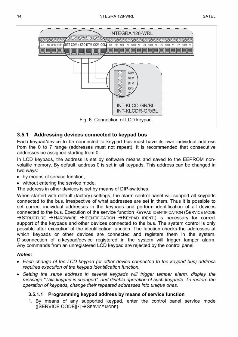
3.5 CONNECTING KEYPADS AND OTHER DEVICES TO KEYPAD BUS Up to 8 different keypads or other devices to be connected to keypad bus can be installed in the system. They are connected in parallel. The data are addressable and all devices function independently. The keypad bus terminals on control panel mainboard have designations COM, +KPD, DTM and CKM. The +KPD output enables powering of the keypad bus devices (the output has a polymer fuse). The distance between the keypad or other device to be connected to keypad bus and the control panel may be up to 300 m. Table 1 shows the number of wires required for correct connection of devices to the keypad bus, if using a 0.5 mm2 cross-section straight-through cable.
+KPD COM CKM DTM Distance Number of wires up to 100 m 1 1 1 1 100-200 m 2 2 1 1 200-300 m 4 4 2 2
Table 1.
Fig. 3. Partial view of keypad board - INT-KLCD-GR/INT-KLCD-BL/INT-KLCDR-GR/
INT-KLCDR-BL.
SATEL Installer Manual 13
Notes: • The signal wires (CKM, DTM and COM) must be run in one cable! • The supply voltage measured across the LCD keypad terminal block with backlight on
should not be less than 11 V DC. • Devices installed far from the control panel may be powered locally from an independent
power source.
Fig. 4. Partial view of keypad board - INT-KLCDS-GR/INT-KLCDS-BL.
Fig. 5. Partial view of keypad board - INT-KLCDK-GR.
Explanations for Figures 3, 4 and 5: 1 - buzzer. 2 - tamper contact. 3 - RS-232 port.
14 INTEGRA 128-WRL SATEL
INTEGRA 128-WRL
INT-KLCD-GR/BL
INT-KLCDR-GR/BL Fig. 6. Connection of LCD keypad.
3.5.1 Addressing devices connected to keypad bus Each keypad/device to be connected to keypad bus must have its own individual address from the 0 to 7 range (addresses must not repeat). It is recommended that consecutive addresses be assigned starting from 0. In LCD keypads, the address is set by software means and saved to the EEPROM non-volatile memory. By default, address 0 is set in all keypads. This address can be changed in two ways: • by means of service function, • without entering the service mode. The address in other devices is set by means of DIP-switches. When started with default (factory) settings, the alarm control panel will support all keypads connected to the bus, irrespective of what addresses are set in them. Thus it is possible to set correct individual addresses in the keypads and perform identification of all devices connected to the bus. Execution of the service function KEYPAD IDENTIFICATION (SERVICE MODE
STRUCTURE HARDWARE IDENTIFICATION KEYPAD IDENT.) is necessary for correct support of the keypads and other devices connected to the bus. The system control is only possible after execution of the identification function. The function checks the addresses at which keypads or other devices are connected and registers them in the system. Disconnection of a keypad/device registered in the system will trigger tamper alarm. Any commands from an unregistered LCD keypad are rejected by the control panel.
Notes: • Each change of the LCD keypad (or other device connected to the keypad bus) address
requires execution of the keypad identification function. • Setting the same address in several keypads will trigger tamper alarm, display the
message "This keypad is changed", and disable operation of such keypads. To restore the operation of keypads, change their repeated addresses into unique ones.
3.5.1.1 Programming keypad address by means of service function 1. By means of any supported keypad, enter the control panel service mode
([SERVICE CODE][*] SERVICE MODE).
SATEL Installer Manual 15
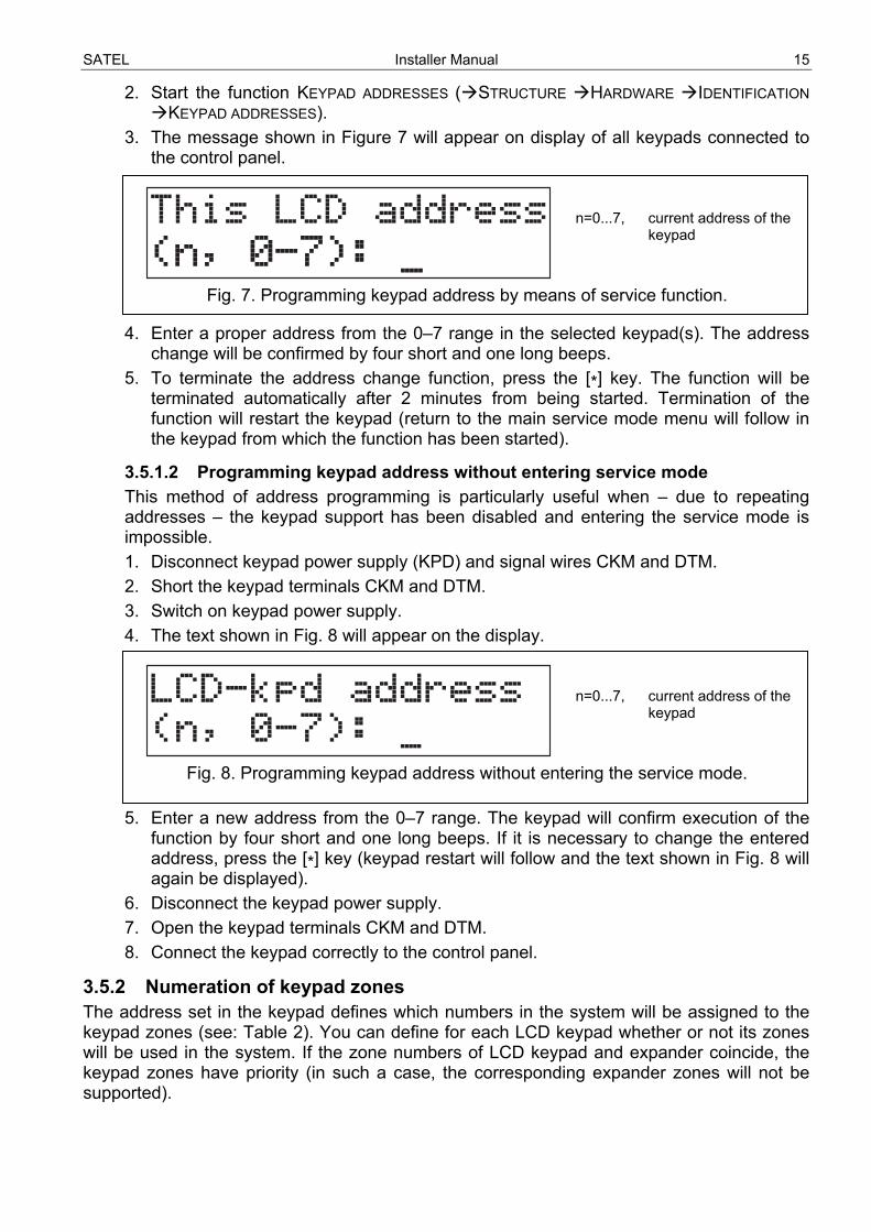
2. Start the function KEYPAD ADDRESSES ( STRUCTURE HARDWARE IDENTIFICATION KEYPAD ADDRESSES).
3. The message shown in Figure 7 will appear on display of all keypads connected to the control panel.
Fig. 7. Programming keypad address by means of service function.
4. Enter a proper address from the 0–7 range in the selected keypad(s). The address
change will be confirmed by four short and one long beeps. 5. To terminate the address change function, press the [*] key. The function will be
terminated automatically after 2 minutes from being started. Termination of the function will restart the keypad (return to the main service mode menu will follow in the keypad from which the function has been started).
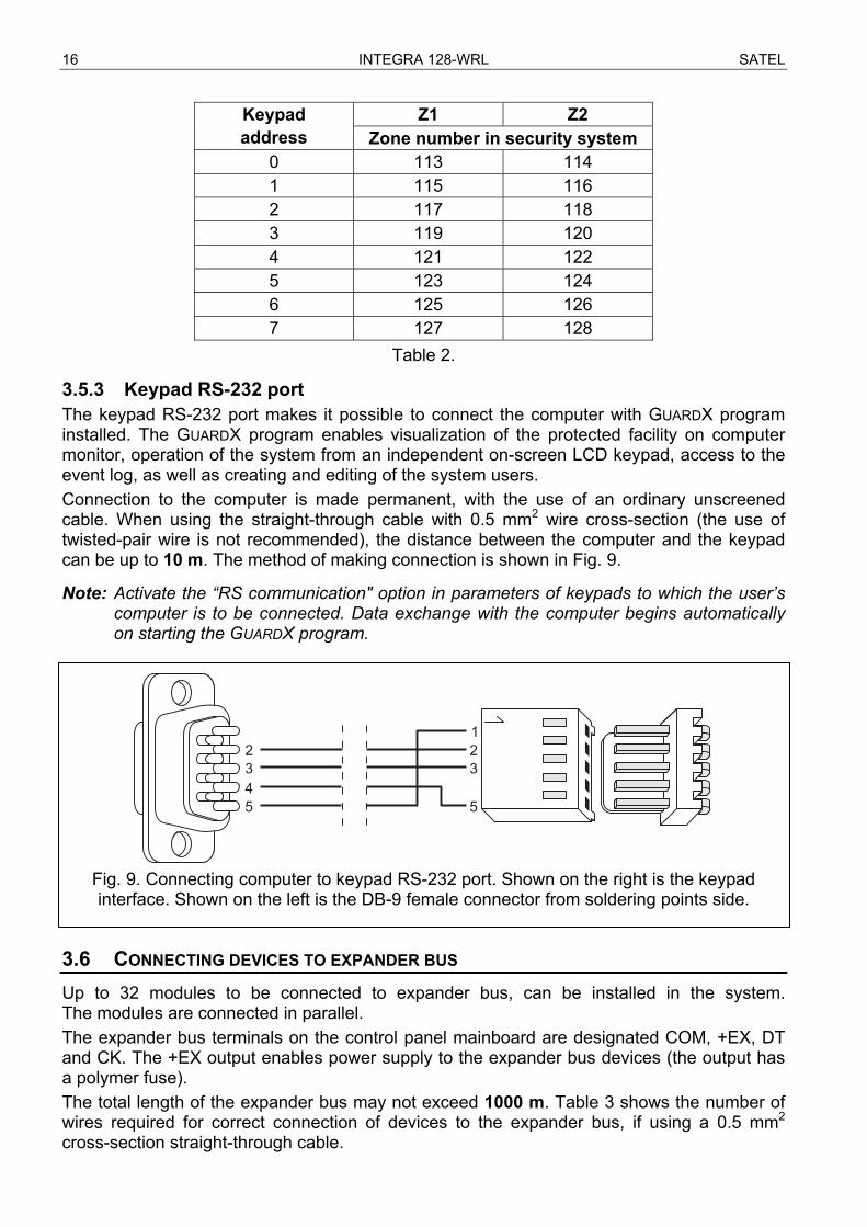
3.5.1.2 Programming keypad address without entering service mode This method of address programming is particularly useful when – due to repeating addresses – the keypad support has been disabled and entering the service mode is impossible. 1. Disconnect keypad power supply (KPD) and signal wires CKM and DTM. 2. Short the keypad terminals CKM and DTM. 3. Switch on keypad power supply. 4. The text shown in Fig. 8 will appear on the display.
Fig. 8. Programming keypad address without entering the service mode.
5. Enter a new address from the 0–7 range. The keypad will confirm execution of the
function by four short and one long beeps. If it is necessary to change the entered address, press the [*] key (keypad restart will follow and the text shown in Fig. 8 will again be displayed).
6. Disconnect the keypad power supply. 7. Open the keypad terminals CKM and DTM. 8. Connect the keypad correctly to the control panel.
3.5.2 Numeration of keypad zones The address set in the keypad defines which numbers in the system will be assigned to the keypad zones (see: Table 2). You can define for each LCD keypad whether or not its zones will be used in the system. If the zone numbers of LCD keypad and expander coincide, the keypad zones have priority (in such a case, the corresponding expander zones will not be supported).
n=0...7, current address of the keypad
n=0...7, current address of the keypad
16 INTEGRA 128-WRL SATEL
Z1 Z2 Keypad
address Zone number in security system 0 113 114 1 115 116 2 117 118 3 119 120 4 121 122 5 123 124 6 125 126 7 127 128
Table 2.
3.5.3 Keypad RS-232 port The keypad RS-232 port makes it possible to connect the computer with GUARDX program installed. The GUARDX program enables visualization of the protected facility on computer monitor, operation of the system from an independent on-screen LCD keypad, access to the event log, as well as creating and editing of the system users. Connection to the computer is made permanent, with the use of an ordinary unscreened cable. When using the straight-through cable with 0.5 mm2 wire cross-section (the use of twisted-pair wire is not recommended), the distance between the computer and the keypad can be up to 10 m. The method of making connection is shown in Fig. 9.
Note: Activate the “RS communication" option in parameters of keypads to which the user’s computer is to be connected. Data exchange with the computer begins automatically on starting the GUARDX program.
1
2
3
5
2
3
4
5
Fig. 9. Connecting computer to keypad RS-232 port. Shown on the right is the keypad interface. Shown on the left is the DB-9 female connector from soldering points side.
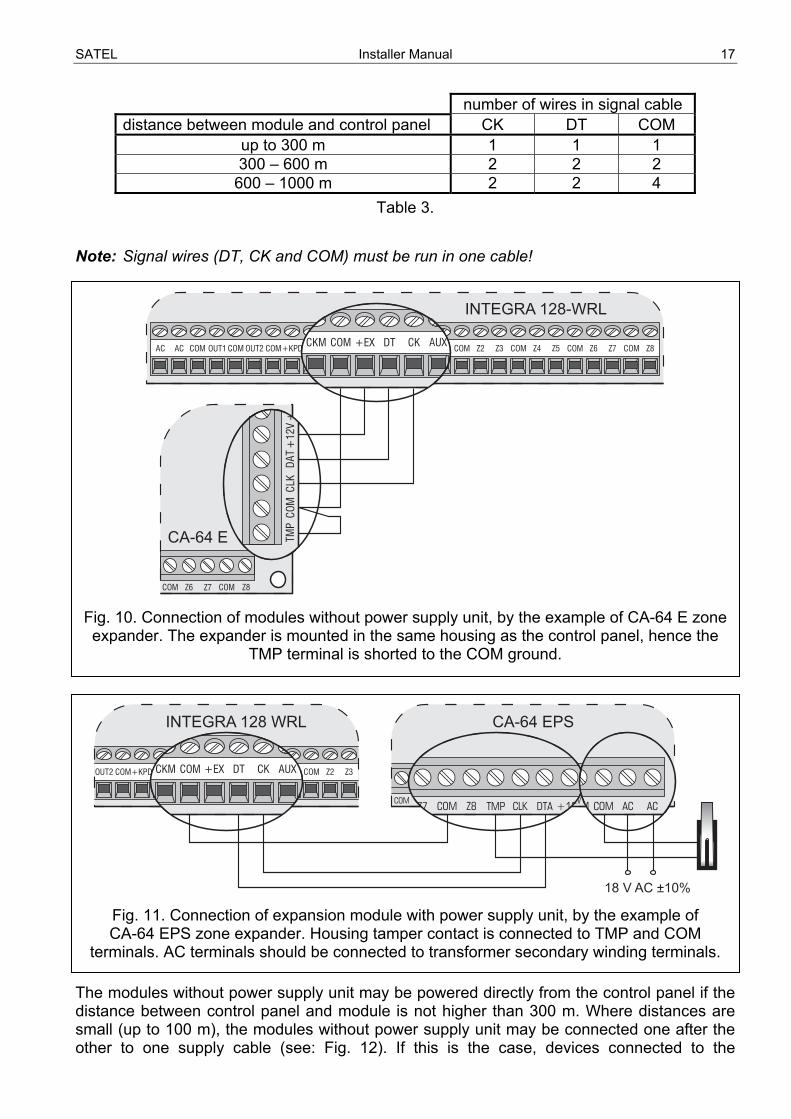
3.6 CONNECTING DEVICES TO EXPANDER BUS Up to 32 modules to be connected to expander bus, can be installed in the system. The modules are connected in parallel. The expander bus terminals on the control panel mainboard are designated COM, +EX, DT and CK. The +EX output enables power supply to the expander bus devices (the output has a polymer fuse). The total length of the expander bus may not exceed 1000 m. Table 3 shows the number of wires required for correct connection of devices to the expander bus, if using a 0.5 mm2
cross-section straight-through cable.
SATEL Installer Manual 17
number of wires in signal cable distance between module and control panel CK DT COM
up to 300 m 1 1 1 300 – 600 m 2 2 2
600 – 1000 m 2 2 4 Table 3.
Note: Signal wires (DT, CK and COM) must be run in one cable!
INTEGRA 128-WRL
CA-64 E
Fig. 10. Connection of modules without power supply unit, by the example of CA-64 E zone expander. The expander is mounted in the same housing as the control panel, hence the
TMP terminal is shorted to the COM ground.
INTEGRA 128 WRL CA-64 EPS
18 V AC ±10%
Fig. 11. Connection of expansion module with power supply unit, by the example of CA-64 EPS zone expander. Housing tamper contact is connected to TMP and COM
terminals. AC terminals should be connected to transformer secondary winding terminals. The modules without power supply unit may be powered directly from the control panel if the distance between control panel and module is not higher than 300 m. Where distances are small (up to 100 m), the modules without power supply unit may be connected one after the other to one supply cable (see: Fig. 12). If this is the case, devices connected to the
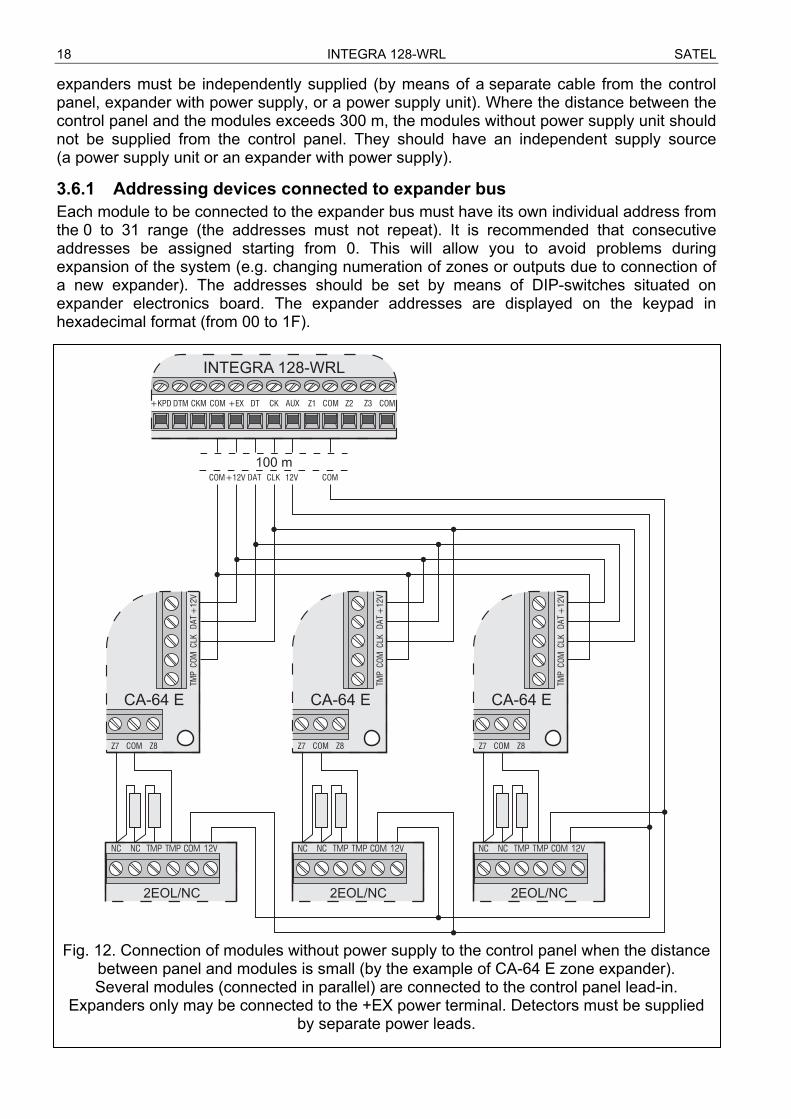
18 INTEGRA 128-WRL SATEL
expanders must be independently supplied (by means of a separate cable from the control panel, expander with power supply, or a power supply unit). Where the distance between the control panel and the modules exceeds 300 m, the modules without power supply unit should not be supplied from the control panel. They should have an independent supply source (a power supply unit or an expander with power supply).
3.6.1 Addressing devices connected to expander bus Each module to be connected to the expander bus must have its own individual address from the 0 to 31 range (the addresses must not repeat). It is recommended that consecutive addresses be assigned starting from 0. This will allow you to avoid problems during expansion of the system (e.g. changing numeration of zones or outputs due to connection of a new expander). The addresses should be set by means of DIP-switches situated on expander electronics board. The expander addresses are displayed on the keypad in hexadecimal format (from 00 to 1F).
100 m
2EOL/NC
NC TMP COM 12VNC TMP
2EOL/NC
NC TMP COM 12VNC TMP
2EOL/NC
NC TMP COM 12VNC TMP
INTEGRA 128-WRL
CA-64 E CA-64 E CA-64 E
Fig. 12. Connection of modules without power supply to the control panel when the distance
between panel and modules is small (by the example of CA-64 E zone expander). Several modules (connected in parallel) are connected to the control panel lead-in.
Expanders only may be connected to the +EX power terminal. Detectors must be supplied by separate power leads.
SATEL Installer Manual 19
The control panel only supports the modules which are registered in the system by means of the EXPANDER IDENTIFICATION service function (SERVICE MODE STRUCTURE HARDWARE
IDENTIFICATION EXPANDER IDENT.). The function saves to the module memory a special (16-bit) number, which is used for checking the module availability in the system. The number is stored in EEPROM non-volatile memory and can only be changed after restarting the expander identification function. Hence, it is impossible to substitute another module for the identified one (even if a correct address is set in it). Substitution of another module for the identified one will trigger alarm (module tamper – verification error). Each change of module or module address requires restarting the expander identification function.
Notes: • The control panel will not support the module unless the identification function is
completed with the "Found xx exp. (yy new)" message. • A wrong module connection can make correct identification of the modules impossible,
which is signaled by the message: “Error! Two expanders have the same addr!". • Too high resistance of the cables connecting the module to the control panel (large
distance, too small number of wires for a single signal) may result in the module being not recognized by the identification function.
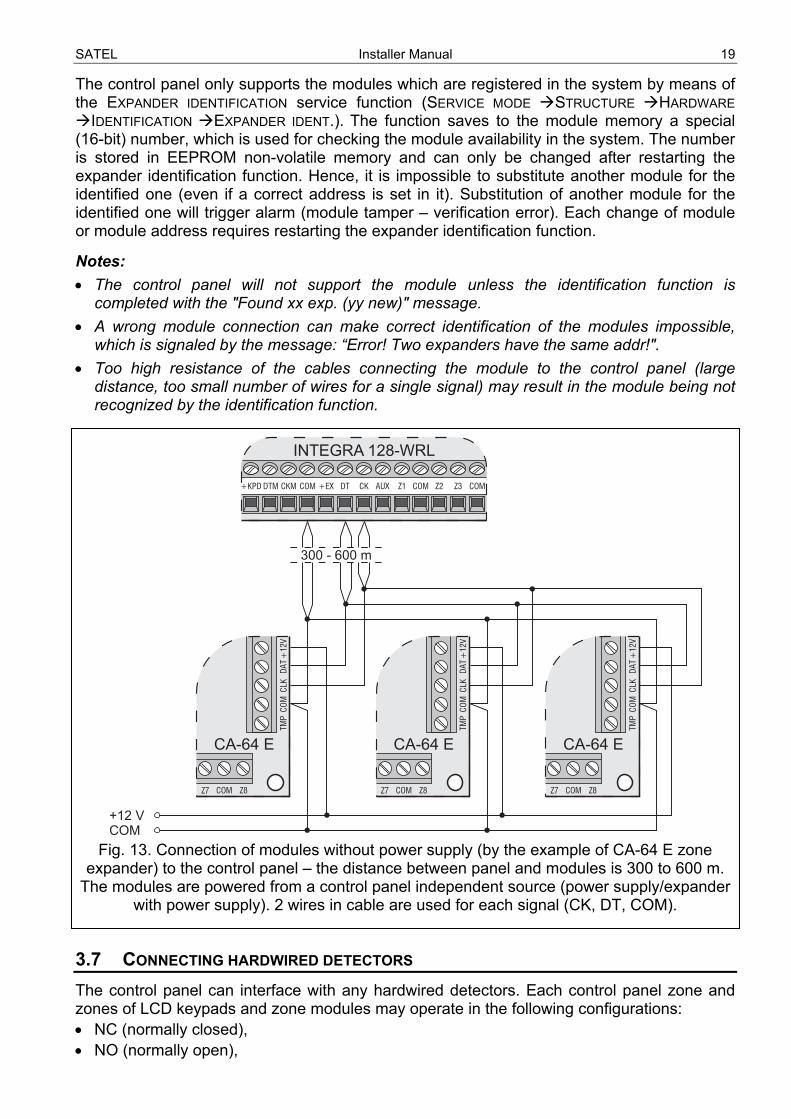
300 - 600 m
+12 V
COM
INTEGRA 128-WRL
CA-64 E CA-64 E CA-64 E
Fig. 13. Connection of modules without power supply (by the example of CA-64 E zone
expander) to the control panel – the distance between panel and modules is 300 to 600 m. The modules are powered from a control panel independent source (power supply/expander
with power supply). 2 wires in cable are used for each signal (CK, DT, COM).
3.7 CONNECTING HARDWIRED DETECTORS The control panel can interface with any hardwired detectors. Each control panel zone and zones of LCD keypads and zone modules may operate in the following configurations: • NC (normally closed), • NO (normally open),
20 INTEGRA 128-WRL SATEL
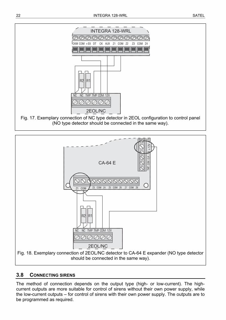
• EOL (end of line resistor), • 2EOL/NC (double end of line resistor, NC type detector), • 2EOL/NO (double end of line resistor, NO type detector). The value of resistors used in EOL and 2EOL configurations is programmable within the range from 500 Ω to 15 kΩ for zones: • on the control panel mainboard – the value of R1 and R2 resistors is programmed
individually for the 2EOL configuration (see Fig. 17). The resistor value for EOL configuration is a sum of values programmed as R1 and R2.
• in the zone expanders identified by the control panel as CA-64 Ei and CA-64 EPSi. Depending on the expander program version, configure the following: – version 4.00 – the value of R1 and R2 resistors for 2EOL configuration (see Fig. 17).
The resistor value for EOL configuration is a sum of values programmed as R1 and R2. – version 2.00 or 2.01 – the resistor value for EOL configuration. For the 2EOL
configuration, a single resistor value equals to half the defined quantity. In order to make the circuit in the zones of LCD keypads and other expanders (CA-64 ADR, INT-IORS, CA-64 PP) in EOL configuration, use 2.2 kΩ resistor, and in 2EOL configuration - 1.1 kΩ resistors. The zones on the mainboard and in zone expanders identified by the control panel as CA-64 Ei and CA-64 EPSi can additionally work in the following configurations: • roller (dedicated for connecting roller shutter motion detector), • vibration (normally closed, dedicated for connecting vibration detector – an NC type of
detector, e.g. magnetic contact, may be connected in series with the vibration detector). All zones in the system can be made dependent on the output status. Activating the output amounts to violation of the zone (the output and the zone does not need to be physically connected). The zone does not need to exist physically, because virtual zones may be used as well. In case of the physically existing zones, programmed as the "follow output" ones, the physical violations and tampers of the zone are disregarded.
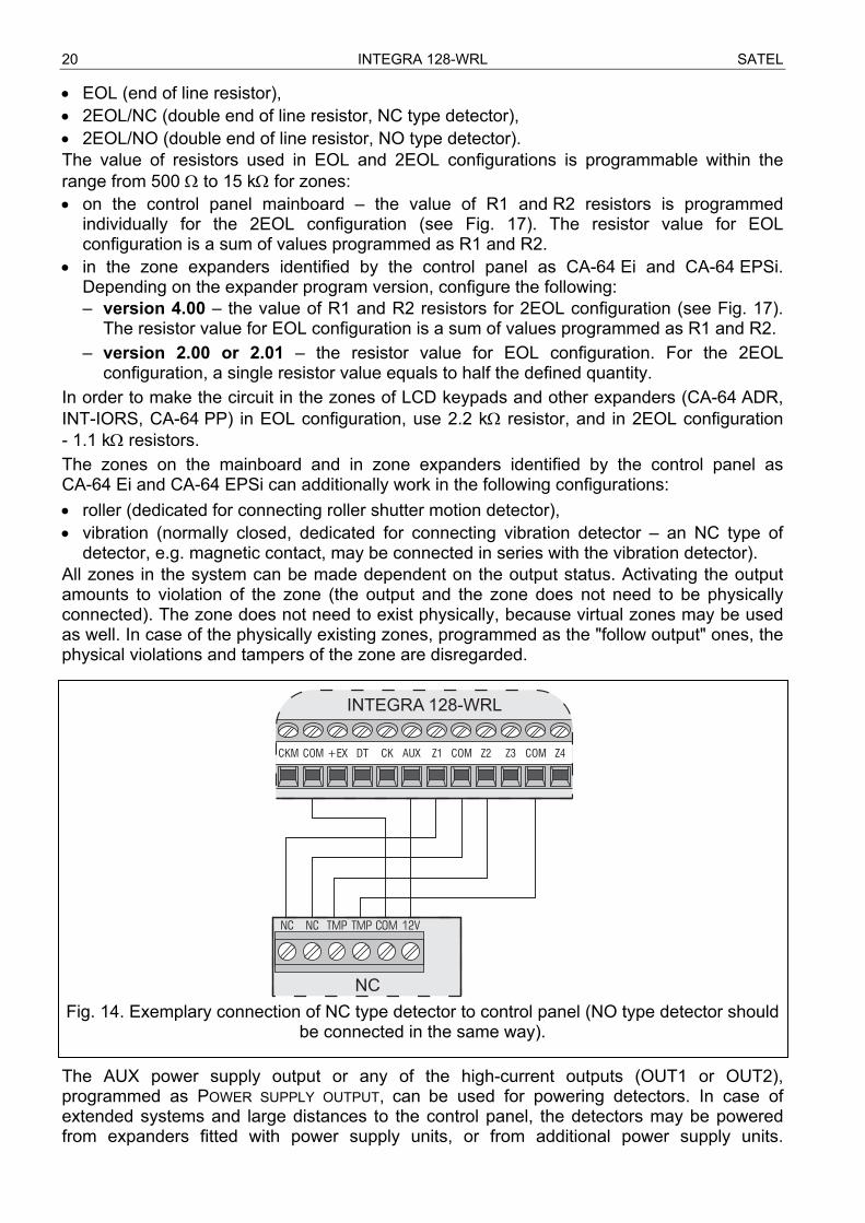
INTEGRA 128-WRL
NC TMP COM 12VNC TMP
NC Fig. 14. Exemplary connection of NC type detector to control panel (NO type detector should
be connected in the same way). The AUX power supply output or any of the high-current outputs (OUT1 or OUT2), programmed as POWER SUPPLY OUTPUT, can be used for powering detectors. In case of extended systems and large distances to the control panel, the detectors may be powered from expanders fitted with power supply units, or from additional power supply units.

SATEL Installer Manual 21
Information on powering detectors connected to expanders can be found in section CONNECTING DEVICES TO EXPANDER BUS. Figures 14, 15, 16 and 17 show various configurations of the detector connections. In the presented examples, the detectors are powered from the AUX output. The signal from the detector is supplied to the Z1 zone of the control panel. The Z2 zone in Figures 14, 15 and 16 has been programmed as type 9 (24H TAMPER). Separating the detector power supply ground from the detector status signal ground eliminates the influence of the resistance of wires on the detector status detection. Assuming that only one detector is connected to the cable and the cable is not very long, the installation may be simplified by running one common single wire for power supply ground and signal ground. The NO, NC detectors in 2EOL configuration are connected in the same way, it is only important to correctly indicate the type of detector connected the control panel (2EOL/NO or 2EOL/NC).
R
INTEGRA 128-WRL
NO TMP COM 12VNO TMP
EOL/NO Fig. 15. Exemplary connection of NO type detector in EOL configuration to control panel.
INTEGRA 128-WRL
R
NC TMP COM 12VNC TMP
EOL/NC Fig. 16. Exemplary connection of NC type detector in EOL configuration to control panel.
22 INTEGRA 128-WRL SATEL
INTEGRA 128-WRL
R1R2
NC TMP COM 12VNC TMP
2EOL/NC Fig. 17. Exemplary connection of NC type detector in 2EOL configuration to control panel
(NO type detector should be connected in the same way).
R1R2
Z1 COM Z2 Z3 Z4 Z5 Z6 Z7 Z8COMCOMCOM
TMP
COM
CLK
DAT
+12
V+
12V
CA-64 E
NC TMP COM 12VNC TMP
2EOL/NC Fig. 18. Exemplary connection of 2EOL/NC detector to CA-64 E expander (NO type detector
should be connected in the same way).
3.8 CONNECTING SIRENS The method of connection depends on the output type (high- or low-current). The high-current outputs are more suitable for control of sirens without their own power supply, while the low-current outputs – for control of sirens with their own power supply. The outputs are to be programmed as required.
SATEL Installer Manual 23
Notes: • If programmable high-current outputs are not used, they should be loaded with 2.2 kΩ
resistor. • The programmable high-current outputs are provided with a load presence detection
circuit, which is active when the output is inactive. If a load is connected correctly and the control panel indicates the “No output load" trouble, connect a 2.2 kΩ resistor in parallel to the load. When the siren connected to the output in parallel to the resistor 2.2 kΩ generates undesirable sounds (when it is not controlled), reduce the resistance value.
• It is recommended that the control panel be started without sirens connected (the high-current outputs should be loaded with 2.2 kΩ resistor). This will prevent alarm from being accidentally triggered when starting the control panel.
INTEGRA 128-WRL
TMPTMP SENS. TMPSASO
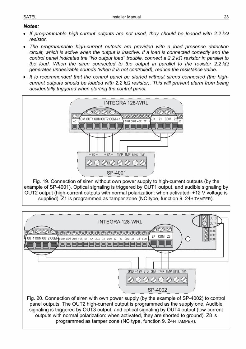
SP-4001 Fig. 19. Connection of siren without own power supply to high-current outputs (by the
example of SP-4001). Optical signaling is triggered by OUT1 output, and audible signaling by OUT2 output (high-current outputs with normal polarization: when activated, +12 V voltage is
supplied). Z1 is programmed as tamper zone (NC type, function 9. 24H TAMPER).
INTEGRA 128-WRL
TMPTMPGND STO STA SENS. TMP12V
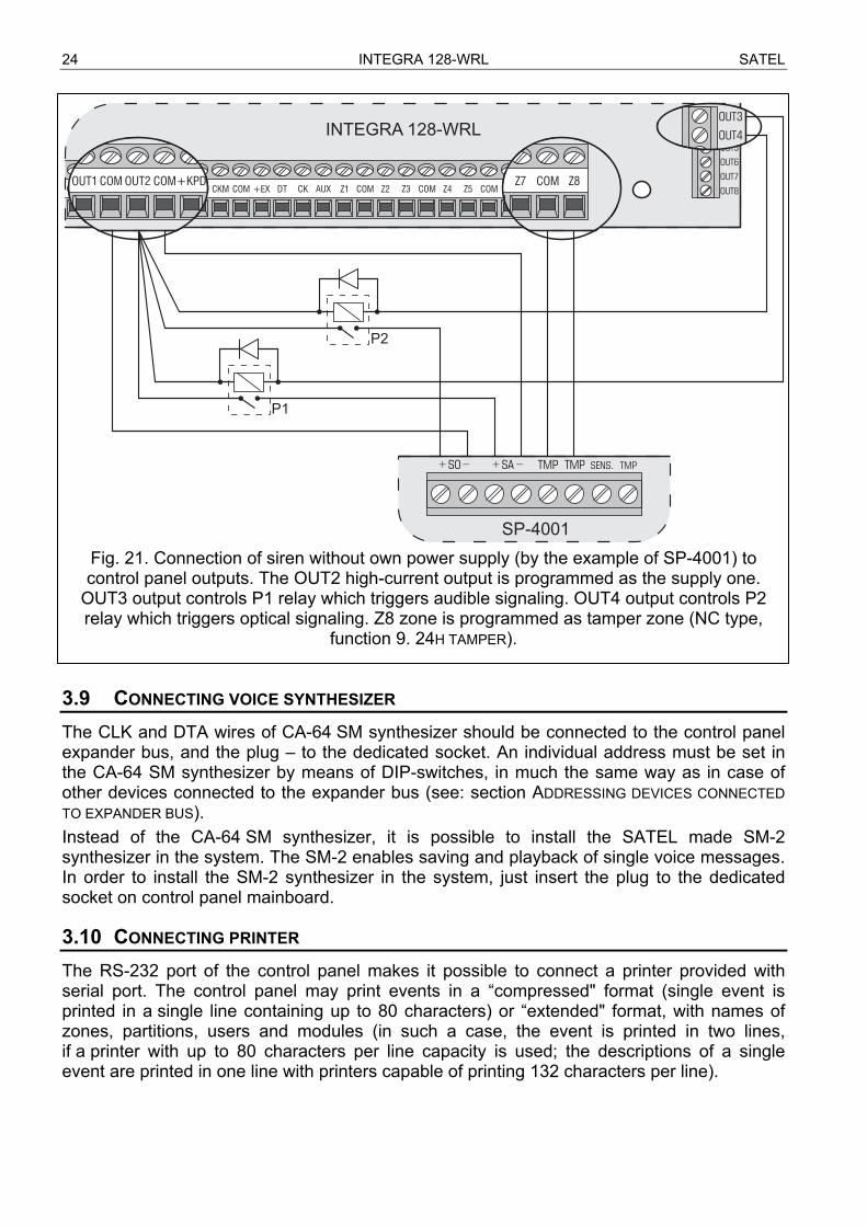
SP-4002 Fig. 20. Connection of siren with own power supply (by the example of SP-4002) to control panel outputs. The OUT2 high-current output is programmed as the supply one. Audible signaling is triggered by OUT3 output, and optical signaling by OUT4 output (low-current
outputs with normal polarization: when activated, they are shorted to ground). Z8 is programmed as tamper zone (NC type, function 9. 24H TAMPER).
24 INTEGRA 128-WRL SATEL
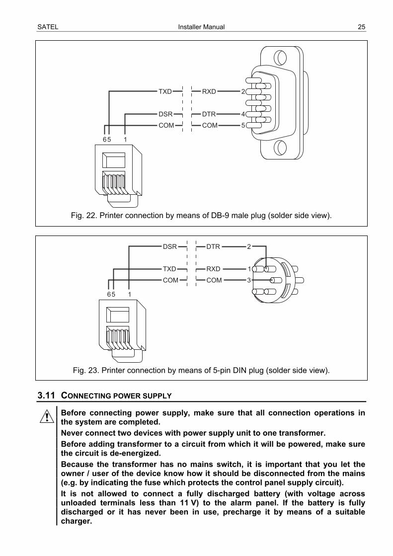
INTEGRA 128-WRL
P2
P1
TMPTMP SENS. TMPSASO
SP-4001 Fig. 21. Connection of siren without own power supply (by the example of SP-4001) to control panel outputs. The OUT2 high-current output is programmed as the supply one.
OUT3 output controls P1 relay which triggers audible signaling. OUT4 output controls P2 relay which triggers optical signaling. Z8 zone is programmed as tamper zone (NC type,
function 9. 24H TAMPER).
3.9 CONNECTING VOICE SYNTHESIZER The CLK and DTA wires of CA-64 SM synthesizer should be connected to the control panel expander bus, and the plug – to the dedicated socket. An individual address must be set in the CA-64 SM synthesizer by means of DIP-switches, in much the same way as in case of other devices connected to the expander bus (see: section ADDRESSING DEVICES CONNECTED TO EXPANDER BUS). Instead of the CA-64 SM synthesizer, it is possible to install the SATEL made SM-2 synthesizer in the system. The SM-2 enables saving and playback of single voice messages. In order to install the SM-2 synthesizer in the system, just insert the plug to the dedicated socket on control panel mainboard.
3.10 CONNECTING PRINTER The RS-232 port of the control panel makes it possible to connect a printer provided with serial port. The control panel may print events in a “compressed" format (single event is printed in a single line containing up to 80 characters) or “extended" format, with names of zones, partitions, users and modules (in such a case, the event is printed in two lines, if a printer with up to 80 characters per line capacity is used; the descriptions of a single event are printed in one line with printers capable of printing 132 characters per line).
SATEL Installer Manual 25
4
5
TXD
COM
DSR
156
2RXD
COM
DTR
Fig. 22. Printer connection by means of DB-9 male plug (solder side view).
TXD
COM
DSR
156
RXD
COM
DTR
1
2
3
Fig. 23. Printer connection by means of 5-pin DIN plug (solder side view).
3.11 CONNECTING POWER SUPPLY
Before connecting power supply, make sure that all connection operations in the system are completed. Never connect two devices with power supply unit to one transformer. Before adding transformer to a circuit from which it will be powered, make sure the circuit is de-energized. Because the transformer has no mains switch, it is important that you let the owner / user of the device know how it should be disconnected from the mains (e.g. by indicating the fuse which protects the control panel supply circuit). It is not allowed to connect a fully discharged battery (with voltage across unloaded terminals less than 11 V) to the alarm panel. If the battery is fully discharged or it has never been in use, precharge it by means of a suitable charger.

26 INTEGRA 128-WRL SATEL
The INTEGRA 128-WRL control panel must be supplied with 18 V (±10%) alternating voltage. Use the transformer secondary winding to supply the mainboard. It is recommended that at least 40 VA transformer be used. The transformer should be permanently connected to the 230 V AC mains. Thus, before you set about making the connections, make yourself familiar with the electric system in the facility. Make sure that the circuit you choose for powering the control panel will be always alive. The power supply circuit should be protected with a proper safety device. A 12 V lead-acid sealed battery should be connected to the control panel as an emergency power source. The battery capacity must be adequately selected to match current consumption in the system. According to CLC/TS 50131-1 Grade 2, the battery must ensure operation of the system without mains supply for 12 hours. It means that in case of the system which fully utilizes the capacity of control panel power supply unit (2 A) a 24 Ah battery must be used.
Note: If the battery voltage drops below 11 V for longer than 12 minutes (3 battery tests), the control panel will indicate battery failure. When the voltage goes down to approx. 9.5 V, the battery will be disconnected.
3.11.1 Power supply connection procedure 1. Deenergize the 230 V AC circuit to which the transformer is to be connected. 2. Connect the 230 V alternating voltage wires to the terminals of transformer primary
winding. 3. Connect the terminals of transformer secondary winding to the AC terminals on module
electronics board. 4. Connect the battery to the dedicated leads (red one to the battery “plus”, black one to
“minus”). The control panel will not start after connecting the battery alone. Included in the control panel set are adapters (matching connectors) for connection of battery with twisted cable ends, therefore the battery cable ends should not be cut off.
5. Turn on 230 V AC power supply in the circuit to which the transformer is connected. The control panel will start operating.
The above mentioned power-up sequence (battery first, 230 V AC mains after) will permit proper operation of the power supply unit and control panel electronic protection circuits, thus preventing defects of the alarm system components which might be caused by possible installation errors. Modules fitted with their own power supply should be started in the same way.
Caution: Should a situation occur when total disconnection of control panel power supply is necessary, disconnect the mains first and then the battery. When reconnecting the power supply, follow the above described sequence (first the battery, then the 230 V AC mains).
3.12 STARTING CONTROL PANEL When the battery is connected and power turned on, the control panel will start. After power-up, the control panel start is proceeding in two stages: 1. First, the STARTER program starts, checking the control panel firmware for possible
damage. If no error is detected, the STARTER launches the control panel program. If an error is detected in the control panel program, the message "Load correct program to the control panel" will be displayed on LCD keypads and the STARTER program will be waiting for a new program from the computer. A program error may only occur when the procedure of control panel firmware updating is disrupted by disconnecting power supply.
SATEL Installer Manual 27
2. The control panel program checks the control panel data saved in the RAM memory (the memory has a battery backup). If no error is detected, the control panel will be started with current settings. If an error is detected in the data saved in RAM memory, the settings will be restored from FLASH memory. A copy of the settings is stored in the FLASH memory. A prompt about saving the copy of settings to FLASH memory is displayed on the LCD keypad when exiting the service mode in case the current settings are changed. In the DLOADX program, you can use the icon to save a copy of settings to FLASH memory. Saving the data to FLASH memory is followed by a restart of the control panel.
The control panel with factory settings (new one or one after restart of settings) supports all keypads connected to the bus. It does not, however, control the status of keypad zones and tamper contacts, and does not provide for programming the security system parameters. Prior to programming the system, you should: 1. Set individual, correct addresses in keypads. 2. Start the keypad identification function (SERVICE MODE STRUCTURE HARDWARE
IDENTIFICATION KEYPAD IDENT.). 3. Start the expander identification function (SERVICE MODE STRUCTURE HARDWARE
IDENTIFICATION EXPAND IDENT.).
3.13 STARTING GSM TELEPHONE
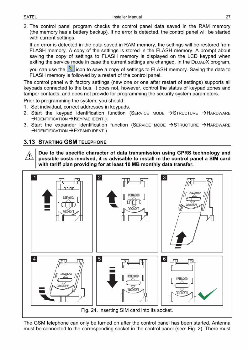
Due to the specific character of data transmission using GPRS technology and possible costs involved, it is advisable to install in the control panel a SIM card with tariff plan providing for at least 10 MB monthly data transfer.
1 2 3
4 5 6
Fig. 24. Inserting SIM card into its socket.
The GSM telephone can only be turned on after the control panel has been started. Antenna must be connected to the corresponding socket in the control panel (see: Fig. 2). There must
28 INTEGRA 128-WRL SATEL
be no cables running in the immediate vicinity of the antenna, as this may cause interference to radio communication. In order to turn on the GSM telephone you should: 1. Make sure that the SUPPORT GSM option is enabled (SERVICE MODE STRUCTURE
HARDWARE GSM SUPPORT GSM). 2. Program the SIM card PIN code. 3. Insert the SIM card into the onboard socket (see: Fig. 24). Telephone logging into the
GSM network may take a few minutes. You can program the PIN code by using the LCD keypad (SERVICE MODE STRUCTURE
HARDWARE GSM PIN CODE) or DLOADX program (window STRUCTURE, tab HARDWARE, branch GSM TELEPHONE). The user function GSM IMEI/V/SIG. ([CODE][#] TESTS GSM IMEI/V/SIG.) makes it possible to check the level of signal received by the antenna, individual telephone identification number and telephone version. If the signal level is equal to 0, GSM/GPRS communication is impossible. The signal level may be equal to 0 in the following cases: • telephone incorrectly turned on (e.g. no SIM card, invalid PIN code, blocked SIM card) – in
such a case, the control panel should report trouble; • antenna not connected or incorrectly connected; • GSM network out of range.
3.14 INSTALLATION OF WIRELESS DEVICES
The battery should be installed in battery-operated wireless devices just before registering them in the system. If the wireless device has no communication with the control panel for 10 minutes, it enters the polling mode, checking for 38 seconds if it is possible to establish communication with the control panel. If it fails to establish communication, it enters the sleep mode for 20 minutes, and then starts checking again for 38 seconds if it can establish communication, etc. This means higher energy consumption and shorter battery life.
Installation of the wireless devices may only begin after the control panel is started, i.e. when it is possible to check the level of radio signal received by the control panel from various devices and, vice versa, by the devices from the control panel. Antenna must be connected to the corresponding socket on the control panel (see: Fig. 2). No cables should run in the immediate vicinity of the antenna, so as not to cause interference to radio communication. The ARF-100 tester, made by SATEL, is a useful device for checking the signal level. The level of signal received by the device / control panel must not be lower than 40%. If the radio signal level at the anticipated installation place is too low, another place should be selected for installation. Sometimes, it is enough to move the device ten to twenty centimeters to achieve a considerable improvement of the signal quality. The device may only be permanently installed after optimal radio signal level is obtained. It is recommended that the wireless devices be installed at high places. Thus it is possible to obtain a better range of radio communication and avoid the risk of the devices being accidentally covered by people moving around the site. Wireless devices should be registered in the system. This can be done by means of LCD keypad or DLOADX program. The control panel mainboard can support up to 48 wireless devices. In fact, this number indicates how many items are available on the list of supported devices. It should be borne in mind when you add to the system devices which take up more than one item on the list. For example, after adding to the system the ACX-200 expander, which occupies 4 items on the list of devices, the control panel will still be able to support 44 other wireless devices.
SATEL Installer Manual 29
When adding and removing the wireless devices, remember that the identification function registers zones and outputs by groups of 8. Already after adding one wireless device which takes up 1 zone, the control panel will reserve 8 zones in the system for wireless devices. The LCD keypad makes it possible to select the zone to which that device will be assigned. It is necessary to observe continuity, i.e. to avoid leaving gaps in the list, which will later reduce the number of available zones in the system. You should also remember to maintain continuity when removing wireless devices from the system. For example, if the devices registered in the control panel occupy 9 items on the list, then 16 zones are reserved in the system (2x8). After removal of the device which occupied item 7 on the list, there will still be 16 zones (2x8) reserved in the system for wireless devices, although 8 items are actually taken up on the list of wireless devices (see: Table 4). In such a case, it is recommended that the last devices be removed from the list and then added to the system again, so as to fill the gap created in the list and reduce the number of zones in the system which are needlessly reserved for wireless devices. In case of devices which also occupy outputs along with zones, it is recommended that they be added to the system first, so as not only to maintain the continuity of utilization of the zones, but of the outputs as well. Shown in Table 4 is situation in which the first output of the siren occupies place 8, and the second output - place 9. As a result, 16 outputs are reserved in the system for wireless devices, though actually 2 are used (the eighth output in the first group of 8 outputs and the first output in the second group of 8 outputs). In some cases, gaps in the list of zones/outputs cannot be avoided. It concerns situations when the number of zones/outputs actually used by the devices is not multiple of 8. The radio communication has been designed so as to make possible operation of several INTEGRA 128-WRL control panels and ACU-100 controllers when their operating ranges overlap. Synchronization with the already working wireless systems is always carried out when turning on the control panel /controller and after each operation of adding/removing the supported devices. The synchronization is performed automatically. The number of wireless devices with overlapping ranges depends on the RESPONSE PERIOD (see: PROGRAMMING manual) and can be from 150 to 450. The higher the frequency of response, the less devices can work with their ranges being mutually overlapped. zones outputs It. list of devices No device No device
1 APD-100 detector 9 APD-100 detector 9 unused/unavailable 2 APD-100 detector 10 APD-100 detector 10 unused/unavailable 3 AMD-100 detector 11 AMD-100 detector 11 unused/unavailable 4 AMD-100 detector 12 AMD-100 detector 12 unused/unavailable 5 AMD-101 detector 13 AMD-101 detector 13 unused/unavailable 6 ^ 14 AMD-101 detector 14 unused/unavailable 7 15 unused/unavailable 15 unused/unavailable 8 ASP-105 siren
8
16 ASP-105 siren 16 ASP-105 siren 9 ^ 17 ASP-105 siren 17 ASP-105 siren 10 18 unused/unavailable 18 unused/unavailable 11 19 unused/unavailable 19 unused/unavailable 12 20 unused/unavailable 20 unused/unavailable 13 21 unused/unavailable 21 unused/unavailable 14 22 unused/unavailable 22 unused/unavailable 15 23 unused/unavailable 23 unused/unavailable 16
8
24 unused/unavailable 17 unused/unavailable Table 4. Example of how wireless devices should not be registered. The system has
reserved 16 zones and 16 outputs for devices occupying 8 items.
30 INTEGRA 128-WRL SATEL
zones outputs It. list of devices no device No device
1 ASP-105 siren 9 ASP-105 siren 9 ASP-105 siren 2 ^ 10 ASP-105 siren 10 ASP-105 siren 3 APD-100 detector 11 APD-100 detector 11 unused/unavailable 4 APD-100 detector 12 APD-100 detector 12 unused/unavailable 5 AMD-100 detector 13 AMD-100 detector 13 unused/unavailable 6 AMD-100 detector 14 AMD-100 detector 14 unused/unavailable 7 AMD-101 detector 15 AMD-101 detector 15 unused/unavailable 8 ^
8
16 AMD-101 detector 16 unused/unavailable Table 5. Example of how to properly register wireless devices. The system has reserved
8 zones and 8 outputs for devices occupying 8 items.
3.14.1 Adding new wireless devices 3.14.1.1 DLOADX program 1. Open the STRUCTURE window, click your mouse on the Hardware TAB, and then on
the WIRELESS SYSTEM branch. 2. Click your mouse on the NEW DEVICE button. The NEW DEVICE window will open. 3. Enter the 7-digit serial number of the device being added. The serial number can be
found on the electronics board or on the housing. Each ARF-100 tester of radio signal level has serial number 0000500.
4. Depending on which device is to be added to the system: − switch on power supply of the ACX-200 or ACX-201 expander, − switch on the ARF-100 tester, − insert the ASW-100 E/ASW-100 F wireless controller into 230 V socket, − insert battery into the ASD-100 detectors, − violate (open) the tamper contact in case of the other devices. If a wrong serial number is entered, a corresponding message will be displayed. In such a case, enter the correct serial number and repeat the above-mentioned operation.
5. A message will confirm that a new device has been added. Click your mouse on the "OK" button to finish the new device adding procedure. You can cancel the new device adding procedure by pressing the "Cancel" button. You can also immediately proceed to adding a next wireless device by pressing the "Next" button.
Note: After completion of the procedure of adding new wireless devices to the system, start the expander identification function.
3.14.1.2 LCD keypad 1. Start the NEW DEVICE function (SERVICE MODE STRUCTURE HARDWARE
EXPANDERS SETTINGS ABAX - MAINBOARD NEW DEVICE). 2. Enter the 7-digit serial number of the device and press the [#] key. The serial number
can be found on the electronics board or on the housing. Each tester of radio signal level has serial number 0000500. If the device with the entered serial number has already been registered, the keypad will signal it by 3 long beeps and will not proceed to the next step of the procedure.
3. Expander identification will be performed automatically (a corresponding message will inform you about it).
4. When the "Open device tamper" message is displayed on the keypad: − switch on power supply of the ACX-200 or ACX-201 expander,
SATEL Installer Manual 31
− switch on the ARF-100 tester, − insert the ASW-100 E/ASW-100 F wireless controller into 230 V socket, − insert battery to the ASD-100 detectors, − violate (open) the tamper contact in case of the other devices. If the serial number of the device being added is different than that previously entered, a suitable message will inform you about it. Press the [*] key and then start the device adding procedure from the beginning.
5. The name and serial number of the new device will be displayed. Press the key 1 to proceed to the next step of the procedure (or press another key to terminate the new device adding procedure).
6. A list of system zones to which the device can be assigned will be displayed on the screen. Select one of them, using the and keys to scroll through the list, and press the [#] key (pressing the [*] key will terminate the new device adding procedure). If the device takes up several zones in the system (e.g. AMD-101 magnetic detector, AVD-100 vibration and magnetic detector, ASP-105 and ASP-205 sirens or ACX-200 and ACX-201 expanders), additional zones (next consecutive after the selected one) will be automatically assigned to it.
7. Expander identification will be performed automatically (a corresponding message will inform you about it).
8. A suggested name for the zone/output assigned to the device will appear on the display. The name is composed of the name and serial number of the device, but any other name can be given to the zone/output. Confirm the name, using the [#] key, or terminate the naming procedure by pressing the [*] key (in such a case, the zone/output will be given a name composed of the name and serial number of the device). If the device occupies several zones/outputs, the procedure is repeated for each of them.
3.14.2 Removing wireless devices 3.14.2.1 DLOADX program 1. Open the STRUCTURE window, click your mouse on the HARDWARE TAB, and then on
the WIRELESS SYSTEM BRANCH. 2. Click your mouse on the device you want to be deleted. 3. Click your mouse on the REMOVE DEVICE button. The Confirm window will open. 4. Click your mouse on the Yes button, to confirm your intention to remove the device.
The device will be removed. Note: After removal of a wireless devices from the system, start the expander
identification function.
3.14.2.2 LCD keypad 1. Start the REMOVE DEVICE function (SERVICE MODE STRUCTURE HARDWARE
EXPANDERS SETTINGS ABAX - MAINBOARD REMOVE DEVICE). 2. Select in the list the device you want to be removed from the system and press [#]. 3. According to the displayed instruction, press the key with number 1, to remove the
device. Removal of the device will be confirmed by the keypad by four short and one long beeps. Pressing any other key instead of the key [1] will bring you back to the selection list of wireless devices.
4. Expander identification will be performed automatically (a corresponding message will inform you about it).

32 INTEGRA 128-WRL SATEL
4. COMPLIANCE WITH CLC/TS 50131-3 REQUIREMENTS To meet the requirements of CLC/TS 50131-3, you must: • reserve two control panel zones for each detector provided with the antimasking function:
a supervision zone, to register violations of the detector, and a technical one, to register triggering of the antimasking feature. If the "maximum zone violation time" programmed for the technical zone is shorter than the antimasking relay cut-off time, a detector trouble will be reported at an attempt to cover the detector;
• use an additional overcurrent protection module (ZB-2) for each power supply output in case of all expansion modules with integrated power supply. The overload signaling output (OVL) should be connected to the control panel zone programmed as type 62 (TECHNICAL – POWER SUPPLY OVERLOAD).
5. TECHNICAL DATA
5.1 CONTROL PANEL MAINBOARD Grade.......................................................................................................................................2 Supply voltage .................................................................................. 18 V AC ±15%, 50–60 Hz Current consumption, standby (with INT-KLCD-GR keypad connected) .......................250 mA Current consumption, max. (with INT-KLCD-GR keypad connected) ............................500 mA Type of control panel power supply ........................................................................................ A Power supply output voltage, rated................................................................. 13.6...13.8 V DC Output voltage range ....................................................................................... 9.5 V…14 V DC Battery failure voltage threshold............................................................................... 11 V ±10% Battery cut-off voltage ............................................................................................. 9.5 V ±10% Power supply output current ................................................................................................ 2 A Current-carrying capacity, high-current programmable outputs ........................................... 2 A Current-carrying capacity, low-current programmable outputs.........................................50 mA Current-carrying capacity, +KPD output.........................................................................500 mA Current-carrying capacity, +EX output ...........................................................................500 mA Current-carrying capacity, AUX output...........................................................................500 mA Battery charging current..........................................................................................400/800 mA Environmental class according to EN50130-5 ......................................................................... II Working temperature range .............................................................................. -10 °C…+55 °C Maximum humidity ..........................................................................................................93±3% Electronics board dimensions ............................................................................... 192x106 mm Housing dimensions (OPU-3P) ..................................................................... 324x382x108 mm Weight (incl. housing and accessories)...........................................................................2130 g
5.2 INT-KLCD-GR / INT-KLCD-BL KEYPAD Supply voltage, rated ......................................................................................... 12 V DC ±15% Current consumption: minimum.......................................................15 mA average ........................................................17 mA maximum....................................................101 mA Environmental class according to EN50130-5 ......................................................................... II Working temperature range ................................................................................ -10°C…+55°C Maximum humidity ..........................................................................................................93±3% Housing dimensions (width x height x depth).................................................. 140x126x26 mm
SATEL Installer Manual 33
Weight............................................................................................................................... 231 g
5.3 INT-KLCDR-GR / INT-KLCDR-BL KEYPAD Supply voltage, rated ......................................................................................... 12 V DC ±15% Current consumption: minimum.......................................................55 mA average ........................................................60 mA maximum....................................................156 mA Environmental class according to EN50130-5 ......................................................................... II Working temperature range ................................................................................ -10°C…+55°C Maximum humidity .......................................................................................................... 93±3% Housing dimensions (width x height x depth)...................................................140x126x26 mm Weight............................................................................................................................... 236 g
5.4 INT-KLCDL-GR / INT-KLCDL-BL KEYPAD Supply voltage, rated ......................................................................................... 12 V DC ±15% Current consumption: minimum.......................................................55 mA average ........................................................61 mA maximum....................................................147 mA Environmental class according to EN50130-5 ......................................................................... II Working temperature range ................................................................................ -10°C…+55°C Maximum humidity .......................................................................................................... 93±3% Housing dimensions (width x height x depth)...................................................145x115x26 mm Weight............................................................................................................................... 217 g
5.5 INT-KLCDS-GR / INT-KLCDS-BL KEYPAD Supply voltage, rated ......................................................................................... 12 V DC ±15% Current consumption: minimum.......................................................30 mA average ........................................................33 mA maximum....................................................151 mA Environmental class according to EN50130-5 ......................................................................... II Working temperature range ................................................................................ -10°C…+55°C Maximum humidity .......................................................................................................... 93±3% Housing dimensions (width x height x depth)..................................................114x94x23.5 mm Weight............................................................................................................................... 141 g
5.6 INT-KLCDK-GR KEYPAD Supply voltage, rated ......................................................................................... 12 V DC ±15% Current consumption: minimum.......................................................25 mA average ........................................................30 mA maximum....................................................110 mA Environmental class according to EN50130-5 ......................................................................... II Working temperature range ................................................................................ -10°C…+55°C Maximum humidity .......................................................................................................... 93±3% Housing dimensions (width x height x depth)...................................................160x126x38 mm Weight............................................................................................................................... 317 g
34 INTEGRA 128-WRL SATEL
6. HISTORY OF THE MANUAL UPDATES Given below is a description of changes as compared with the manual for the control panel with firmware in version v1.06.
DATE FIRMWARE VERSION INTRODUCED CHANGES
2009-08 1.07 • Some figures have been modified. • Section "Wireless devices" has been complemented by information about new
devices supported by the control panel (p. 8). • Description of keypad address programming by using the service function has
been modified: after restart, the keypad remains in the service mode (p. 14). • Information on connecting detectors in EOL and 2EOL configurations has been
modified to reflect the option of individual programming of values for both resistors used in 2EOL configuration (p. 20).
• A note has been added regarding the SIM card in case of data transmission by means of GPRS technology (p. 27).
ATTENTION! An efficient security system does not prevent burglary, assault or fire from happening, however it diminishes the risk that such a situation will cause no alarm or notification.
Therefore, the SATEL Company recommends that operation of the whole security system be regularly tested.
SATEL sp. z o.o. ul. Schuberta 79 80-172 Gdańsk
POLAND tel. + 48 58 320 94 00
[email protected] www.satel.eu