Embed Size (px)
Citation preview
TroubleshootingC15 On-highway Engines
Media Number -RENR5088-06 Publication Date -01/07/2007 Date Updated -10/07/2007
i02818906
Intake Valve Actuator Response - Test
SMCS - 5479-038-IL
System Operation Description:
The Intake Valve Actuation system (IVA) uses pressurized engine oil to delay the closingof the intake valves. The system is controlled by the Engine Control Module (ECM). Thesystem contains the following components:
Check Valve (3) - Pressurized engine oil flows to a rail inside the valve cover base. Acheck valve prevents oil from flowing from the rail back to the main oil gallery.
Pressure Sensor (2) - A pressure sensor is threaded into the rail. The sensor converts therail pressure into an electrical signal. The ECM monitors the signal in order to determinethe pressure of the oil in the rail.
Control Valve (1) - A control valve is threaded into the rail. The control valve contains acoil and a cartridge assembly. The cartridge assembly contains a spool. The spool isnormally closed. When the spool is closed, the oil is contained in the rail. The ECMsends a signal to the coil in order to fully open the spool. The oil is released into the spaceunderneath the valve cover and the rail pressure is reduced.
Actuator (4) - The actuators are located under the valve covers. Pressurized engine oilflows from the rail to each actuator. The actuators use the pressurized engine oil andelectrical commands from the ECM in order to delay the closing of the intake valves.
View Image
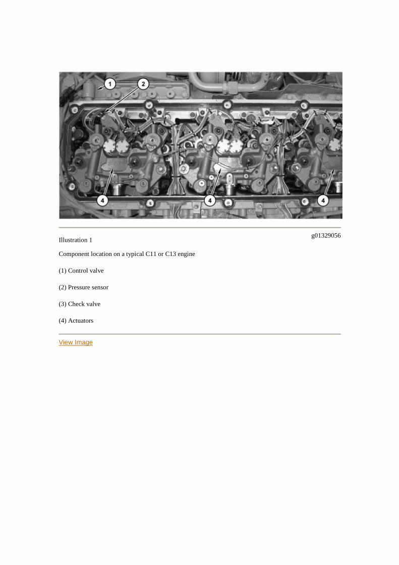
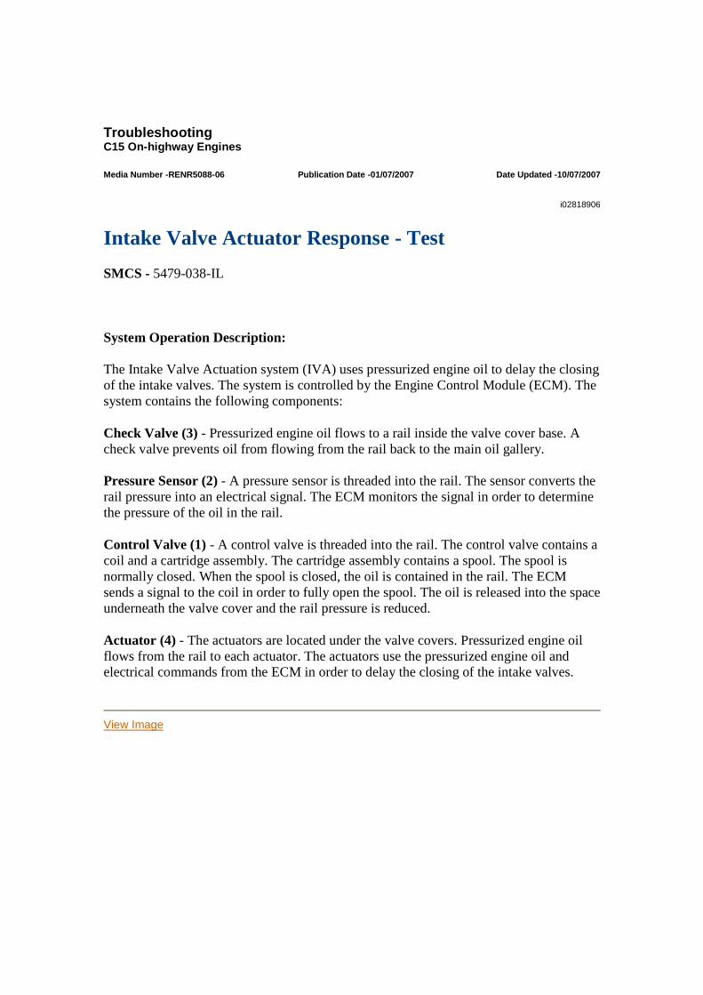
Illustration 1g01329056
Component location on a typical C11 or C13 engine
(1) Control valve
(2) Pressure sensor
(3) Check valve
(4) Actuators
View Image
Illustration 2g01329140
Component location on a typical C15 engine
(1) Control valve
(2) Pressure sensor
(3) Check valve
(4) Actuators
System Operation During Engine Start
The ECM performs the following sequence of operations every time the engine is started:
The ECM commands the control valve to open for 17 seconds. The ECM checks the temperature of the coolant. The ECM commands the control valve to close when the coolant temperature
exceeds 20 °C (68 °F). This allows the temperature of the oil in the rail to warmup.
The ECM commands the control valve to open. The ECM samples the railpressure. The ECM commands the control valve to close. The ECM takes asecond sample of the rail pressure. The ECM compares the two pressure values.The ECM activates a 283-7 code if the pressure difference is too low.
The control valve should remain closed during engine operation.
System Operation During Engine Operation
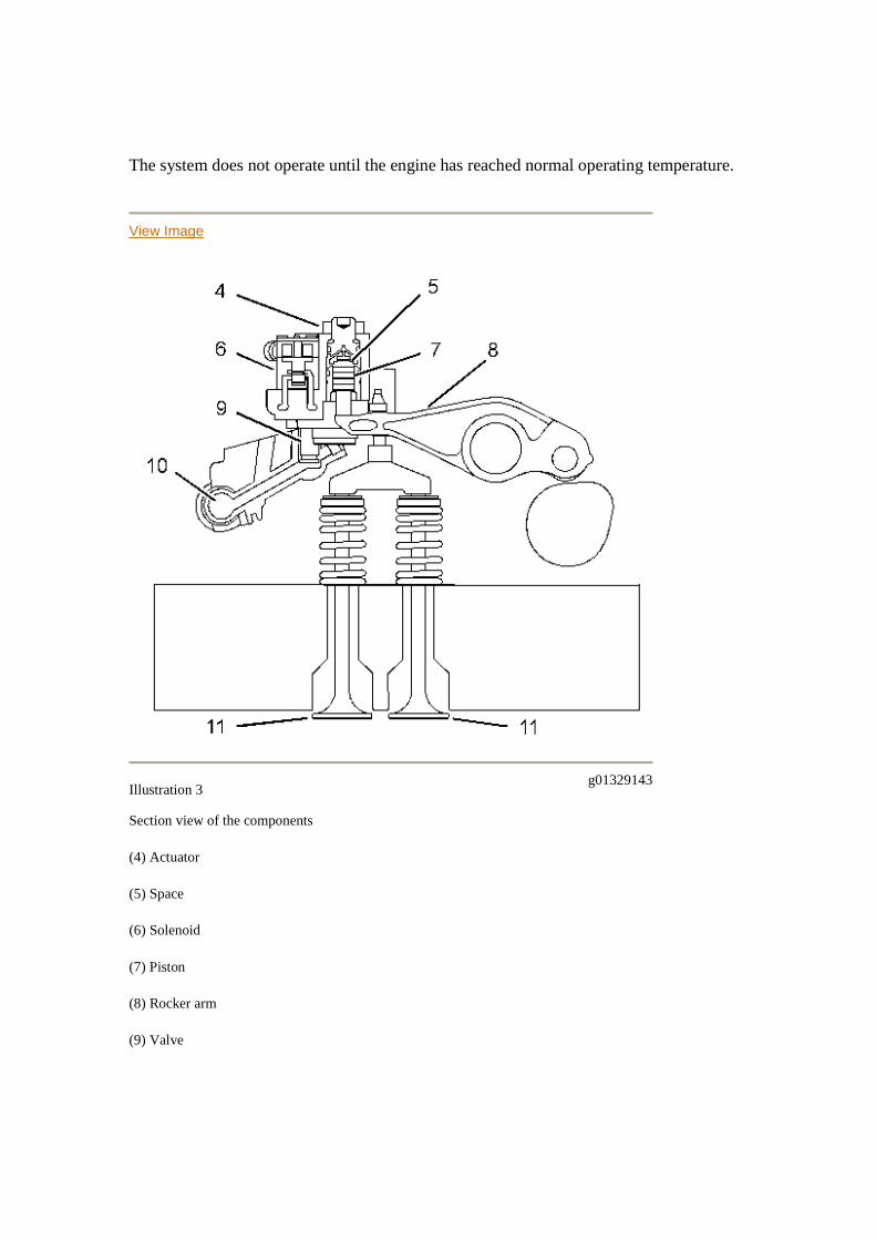
The system does not operate until the engine has reached normal operating temperature.
View Image
Illustration 3g01329143
Section view of the components
(4) Actuator
(5) Space
(6) Solenoid
(7) Piston
(8) Rocker arm
(9) Valve
(10) Rail
(11) Intake valves
Each actuator (4) contains two solenoids (6) . Each solenoid is connected to a valve (9) .The solenoid is normally de-energized. The valve is normally open. This allows oil toflow between rail (10) and the space (5) above piston (7) .
Rocker arm (8) is down when the intake valves are open. Pressurized oil flows from rail(10) to space (5) above piston (7) . This causes the piston to move down. The pistoncontacts rocker arm (8) .
The ECM energizes solenoid (6) when the ECM requires intake valves (11) to remainopen. The energized solenoid closes valve (9) . This traps the oil in space (5) . Thetrapped oil causes piston (7) and rocker arm (8) to remain down. This keeps intake valves(11) open.
The ECM de-energizes solenoid (6) when the ECM requires the intake valves to close.The de-energized solenoid lifts valve (9) . Valve springs (9) raise intake valves (11) ,rocker arm (8) , and piston (7) . The rising piston forces the oil from space (5) into rail(10) .
The flow of oil into the rail changes the pressure of the oil in the rail. The ECM monitorsthe rail pressure. The ECM determines if the changes in rail pressure are correct for thecommands that were sent to a particular solenoid. The ECM activates a diagnostic codefor the appropriate cylinder if the changes in rail pressure are incorrect for that solenoid.
Troubleshooting Procedure
Use this procedure to diagnose mechanical problems with the intake valve actuationsystem. The following diagnostic codes indicate that there is a mechanical problem withthe system:
Table 1
Diagnostic Codes for Mechanical Problems with the Intake Valve Actuation System
CodeDescription Conditions Which Can Cause The Code
283-7Intake ValveActuation OilPressure notresponding
This code can only occur soon after the engine has started.
This code indicates that the difference in rail pressure isincorrect while the control valve is opened and closed. Thefollowing conditions can cause this code:
A control valve that contains debris or a control valve that isnot operating correctly.
Damaged O-ring seal or missing O-ring seal. The O-ringseals are at location (19) in Illustration 12 and locations (26)and (27) in Illustration 15.
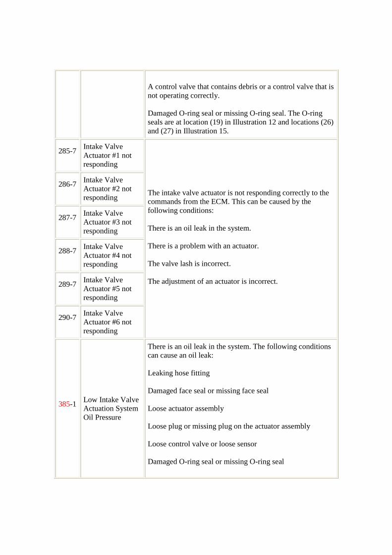
285-7Intake ValveActuator #1 notresponding
286-7Intake ValveActuator #2 notresponding
287-7Intake ValveActuator #3 notresponding
288-7Intake ValveActuator #4 notresponding
289-7Intake ValveActuator #5 notresponding
290-7Intake ValveActuator #6 notresponding
The intake valve actuator is not responding correctly to thecommands from the ECM. This can be caused by thefollowing conditions:
There is an oil leak in the system.
There is a problem with an actuator.
The valve lash is incorrect.
The adjustment of an actuator is incorrect.
385-1Low Intake ValveActuation SystemOil Pressure
There is an oil leak in the system. The following conditionscan cause an oil leak:
Leaking hose fitting
Damaged face seal or missing face seal
Loose actuator assembly
Loose plug or missing plug on the actuator assembly
Loose control valve or loose sensor
Damaged O-ring seal or missing O-ring seal
Low oil level
The check valve is stuck open. The rail pressure cannotmaintain the desired value if the check valve is stuck open.
The control valve remains partially open. This conditionallows the oil to continuously leak out of the rail. Thiscondition can be caused by debris or by abuse. Theseconditions hinder the movement of the valve's internalcomponents. If the control valve is partially open, a 283-7code is usually activated in addition to the 385-1 code.
Follow the troubleshooting procedure in order to identify the root cause of the problem.
Note: Resolve any electrical problems with the system before you use this procedure.
Symptoms
The following symptoms may occur if there is a problem with the intake valve actuationsystem.
Intermittent check engine light Intermittent reductions in engine power
You may need to perform a road test in order to verify that the problem is resolved. If aroad test is performed on the engine, the road test must be carried out under loadedconditions. The test must be performed at 75 percent of the engine's rated fuel rate for atleast 30 seconds.
Check the box or fill in the appropriate answer in the appropriate section of each test step.Complete all of the pages. Return this information with the returned part and thetroubleshooting guide. Ensure that the items are properly packaged in order to preventdamage during shipment.
If snapshots are available of the fault codes, provide a copy of the snapshots with thereturned part. If snapshots are not available, please answer the following questions andreturn this sheet with the returned part.
Engine serial number ________ Dealer code ________ Outside temperature at time of fault ________ Engine coolant temperature at time of fault ________ Fault codes that were present ________
Also, answer the following questions concerning the basic operating conditions:
Did the fault occur immediately after the initial engine start-up ________ Did the fault occur after the first heavy pull of the day ________ Approximate time the faults started to occur after starting to drive (example: one
hour or two hours after starting out) ________ Approximate engine speed ________. Approximate fuel position ________.
Test Step 1. Check the Engine Oil Level
A. Stop the engine. Allow the engine to cool approximately 20 minutes so the oillevel can stabilize.
B. Check the engine oil level.
Expected Result:
________Result 1 The engine oil level is "OK".
________Result 2 The engine oil level is low.
________Result 3 The engine oil level is high.
Results:
RESULT 1 - The engine oil level is OK.
Repair: Record the engine oil level. ________.Verify that the dipstick iscalibrated correctly. Refer to Operation and Maintenance Manual, "Engine OilLevel Gauge - Calibrate".
Proceed to Test Step 2.
RESULT 2 - The engine oil level is low.
Repair: Verify that the dipstick is calibrated correctly. Refer to Operation andMaintenance Manual, "Engine Oil Level Gauge - Calibrate".Add engine oil to theproper level.Record the amount of engine oil that was added. ________Road testthe vehicle. Verify that the repair resolved the problem.
If the problem has not been eliminated, proceed to Test Step 2.
RESULT 3 - The engine oil level is high.
Repair: Verify that the dipstick is calibrated correctly. Refer to Operation andMaintenance Manual, "Engine Oil Level Gauge - Calibrate".Record the amount of
engine oil that was drained. ________Road test the vehicle. Verify that the repairresolved the problem.
If the problem has not been eliminated, proceed to Test Step 2.
Test Step 2. Check the Engine Oil Pressure
A. Turn the keyswitch OFF.
B. Connect the Caterpillar Electronic Technician (ET) to the service tool connector.
C. Install a mechanical gauge to the engine in order to read engine oil pressure.
D. Start the engine and allow the engine to warm up to operating temperature.
E. Monitor the status for "Engine Oil Pressure" on Cat ET while the engine isoperated throughout the rpm range. Also check the value on the mechanicalgauge.
F. Verify that the oil pressure is above the trip point in Illustration 4 or Illustration 5.
G. Turn the keyswitch OFF.
View Image
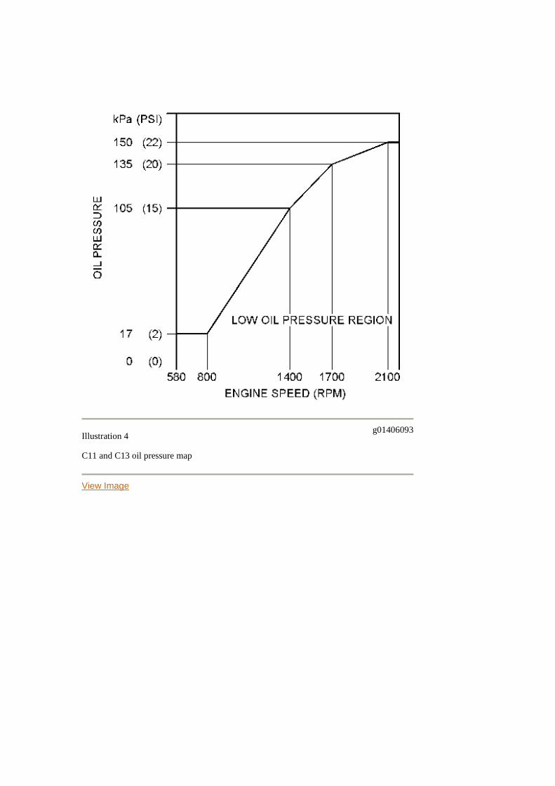
Illustration 4g01406093
C11 and C13 oil pressure map
View Image
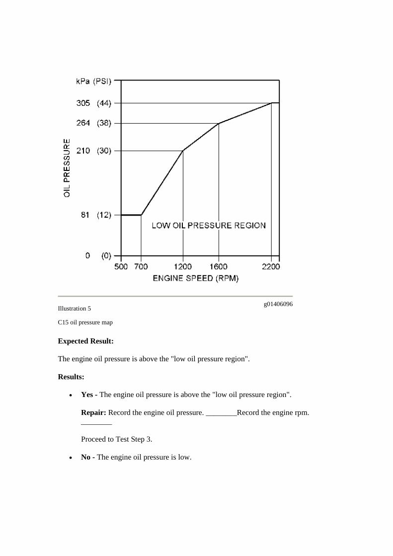
Illustration 5g01406096
C15 oil pressure map
Expected Result:
The engine oil pressure is above the "low oil pressure region".
Results:
Yes - The engine oil pressure is above the "low oil pressure region".
Repair: Record the engine oil pressure. ________Record the engine rpm.________
Proceed to Test Step 3.
No - The engine oil pressure is low.

Repair: Record the engine oil pressure. ________Record the engine rpm.________If there are any active diagnostic codes that are related to low oilpressure, refer to the appropriate topic in Troubleshooting, "Troubleshooting witha Diagnostic Code".If the pressure is constant throughout the rpm range, there is aproblem with the circuit for the engine oil pressure sensor. Check the wire for thepressure sensor supply (terminal A) for an open circuit.If there are no diagnosticcodes that are related to low oil pressure, refer to Testing and Adjusting, "EngineOil Pressure - Test".Road test the vehicle in order to verify that the problem hasbeen resolved.
Proceed to Test Step 8.
Test Step 3. Determine the Logged Code
A. Turn the keyswitch ON.
B. Check for the following logged diagnostic codes:
Note: Repair all electrical faults before troubleshooting the diagnostic codes thatare listed below.
o 283-7 Intake Valve Actuation Oil Pressure not respondingo 385-1 Low Intake Valve Actuation System Oil Pressureo 285-7 through 290-7 Intake Valve Actuator not responding
Expected Result:
________Result 1 Diagnostic codes that have -5 or -6 fault code extensions are logged.
________Result 2 283-7 is logged.
________Result 3 385-1 is logged.
________Result 4 285-7 through 290-7 are logged.
Results:
RESULT 1 - Diagnostic codes with -5 or -6 extensions are active or logged.
Repair: Refer to Troubleshooting, "Intake Actuator Circuit - Test".
STOP
RESULT 2 - 283-7 is active or logged. Proceed to Test Step 4. RESULT 3 - 385-1 is active or logged. Proceed to Test Step 5. RESULT 4 - 285-7 to 290-7 are active or logged. Proceed to Test Step 8.
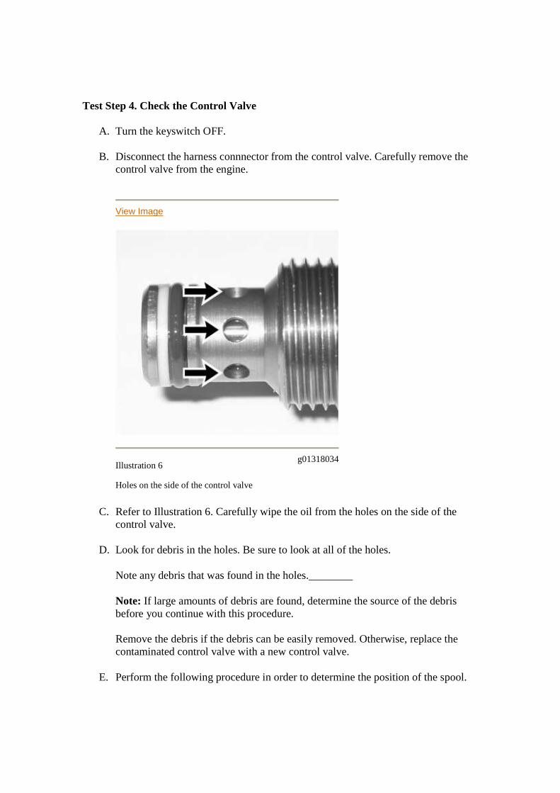
Test Step 4. Check the Control Valve
A. Turn the keyswitch OFF.
B. Disconnect the harness connnector from the control valve. Carefully remove thecontrol valve from the engine.
View Image
Illustration 6g01318034
Holes on the side of the control valve
C. Refer to Illustration 6. Carefully wipe the oil from the holes on the side of thecontrol valve.
D. Look for debris in the holes. Be sure to look at all of the holes.
Note any debris that was found in the holes.________
Note: If large amounts of debris are found, determine the source of the debrisbefore you continue with this procedure.
Remove the debris if the debris can be easily removed. Otherwise, replace thecontaminated control valve with a new control valve.
E. Perform the following procedure in order to determine the position of the spool.
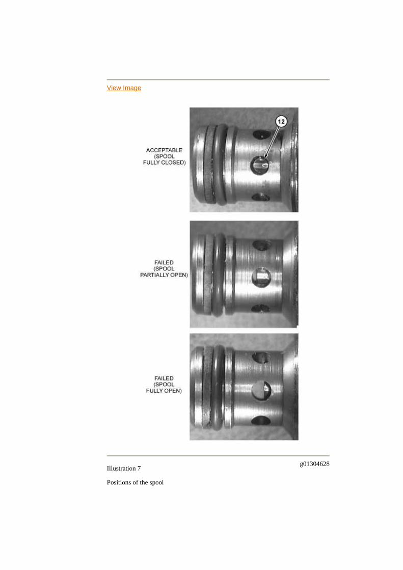
View Image
Illustration 7g01304628
Positions of the spool
When the valve is fully open, the spool blocks approximately 40 percent of the hole.
(12) Spool
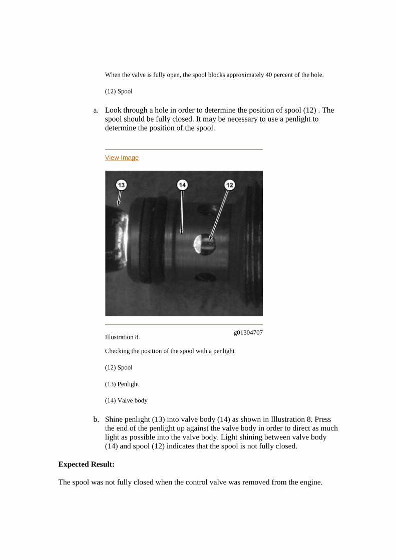
a. Look through a hole in order to determine the position of spool (12) . Thespool should be fully closed. It may be necessary to use a penlight todetermine the position of the spool.
View Image
Illustration 8g01304707
Checking the position of the spool with a penlight
(12) Spool
(13) Penlight
(14) Valve body
b. Shine penlight (13) into valve body (14) as shown in Illustration 8. Pressthe end of the penlight up against the valve body in order to direct as muchlight as possible into the valve body. Light shining between valve body(14) and spool (12) indicates that the spool is not fully closed.
Expected Result:
The spool was not fully closed when the control valve was removed from the engine.
Results:
Yes - The spool was not fully closed when the control valve was removed fromthe engine.
Repair: Perform the following procedure:
1. Replace the control valve.
2. Clear all logged diagnostic codes.
3. Start the engine and run the engine until the engine coolant temperature isat least 20 °C (68 °F).
4. Look for a 283-7 diagnostic code.
If the 283-7 diagnostic code does not return, return the engine to service. If the283-7 diagnostic code returns, further testing is required in order to determine theroot cause. Proceed to Test Step 5.
No - The spool was fully closed when the control valve was removed from theengine. Further testing is required in order to determine the root cause. Proceed toTest Step 5.
Test Step 5. Perform a Leak Test
Review the following information before you perform the leak test.
It is normal for oil to flow from some locations during this test. The locations for oil flowon C11 and C13 engines are shown in Illustration 19. The locations for oil flow on C15engines are shown in Illustration 21.
View Image
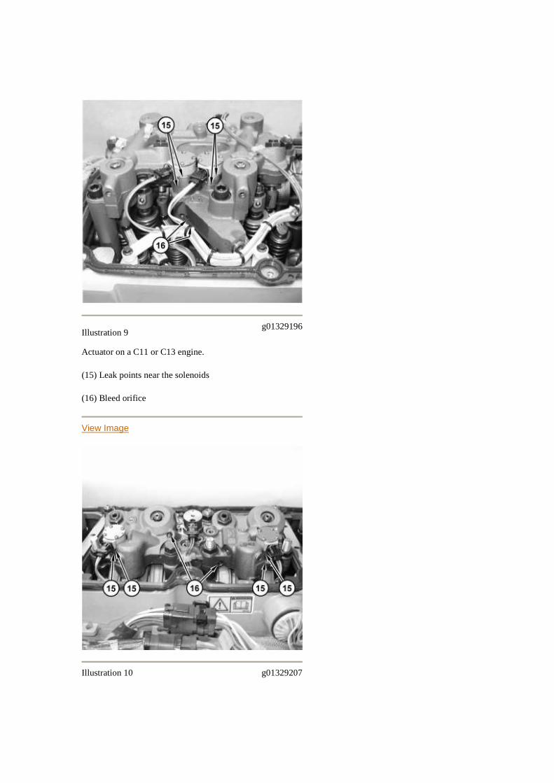
Illustration 9g01329196
Actuator on a C11 or C13 engine.
(15) Leak points near the solenoids
(16) Bleed orifice
View Image
Illustration 10 g01329207
Actuator on a C15 engine.
(15) Leak points near the solenoids
(16) Bleed orifices
Leak Points Near the Solenoids - Clearances for moving hydraulic components maycause slight oil leakage from locations (15) .
Bleed Orifice - Bleed orifice (16) allows air to purge from the actuator. The bleed orificeis located on the bottom of some actuators. Oil should stream from each bleed orificeduring this test.
Oil should not flow from some locations. The following problems can cause oil to flowfrom these locations:
Missing O-ring seal or damaged O-ring seal A component is loose A component has an internal failure
The locations where oil should not flow on C11 and C13 engines are shown inIllustrations 21, 22, and 23. The locations where oil should not flow on C15 engines areshown in Illustrations 24, 25, and 26.
View Image
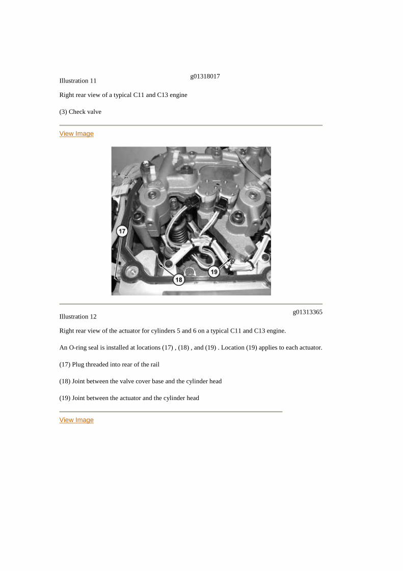
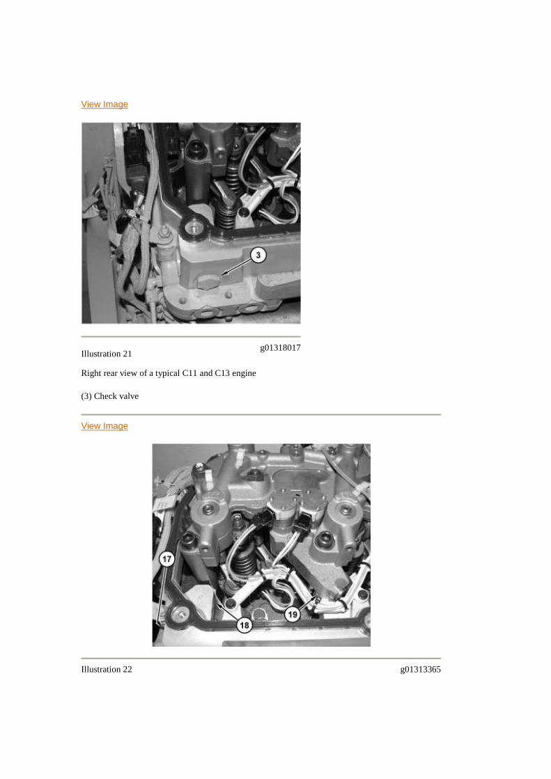
Illustration 11g01318017
Right rear view of a typical C11 and C13 engine
(3) Check valve
View Image
Illustration 12g01313365
Right rear view of the actuator for cylinders 5 and 6 on a typical C11 and C13 engine.
An O-ring seal is installed at locations (17) , (18) , and (19) . Location (19) applies to each actuator.
(17) Plug threaded into rear of the rail
(18) Joint between the valve cover base and the cylinder head
(19) Joint between the actuator and the cylinder head
View Image
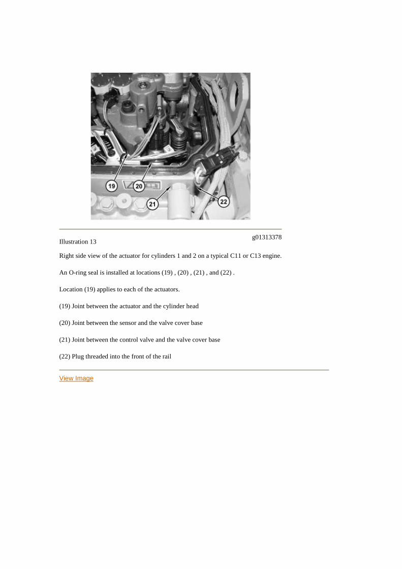
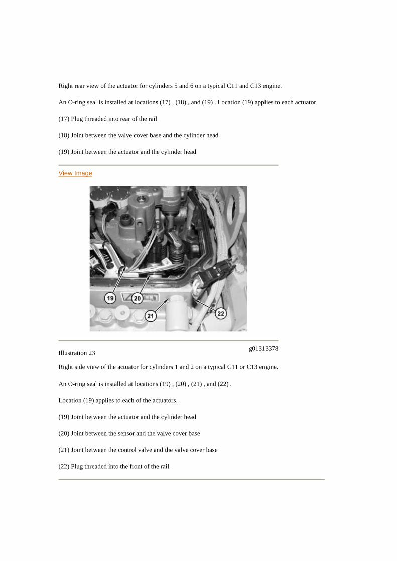
Illustration 13g01313378
Right side view of the actuator for cylinders 1 and 2 on a typical C11 or C13 engine.
An O-ring seal is installed at locations (19) , (20) , (21) , and (22) .
Location (19) applies to each of the actuators.
(19) Joint between the actuator and the cylinder head
(20) Joint between the sensor and the valve cover base
(21) Joint between the control valve and the valve cover base
(22) Plug threaded into the front of the rail
View Image
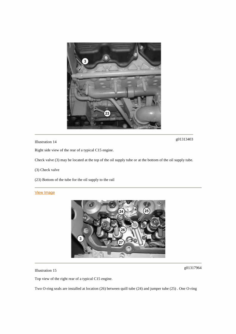
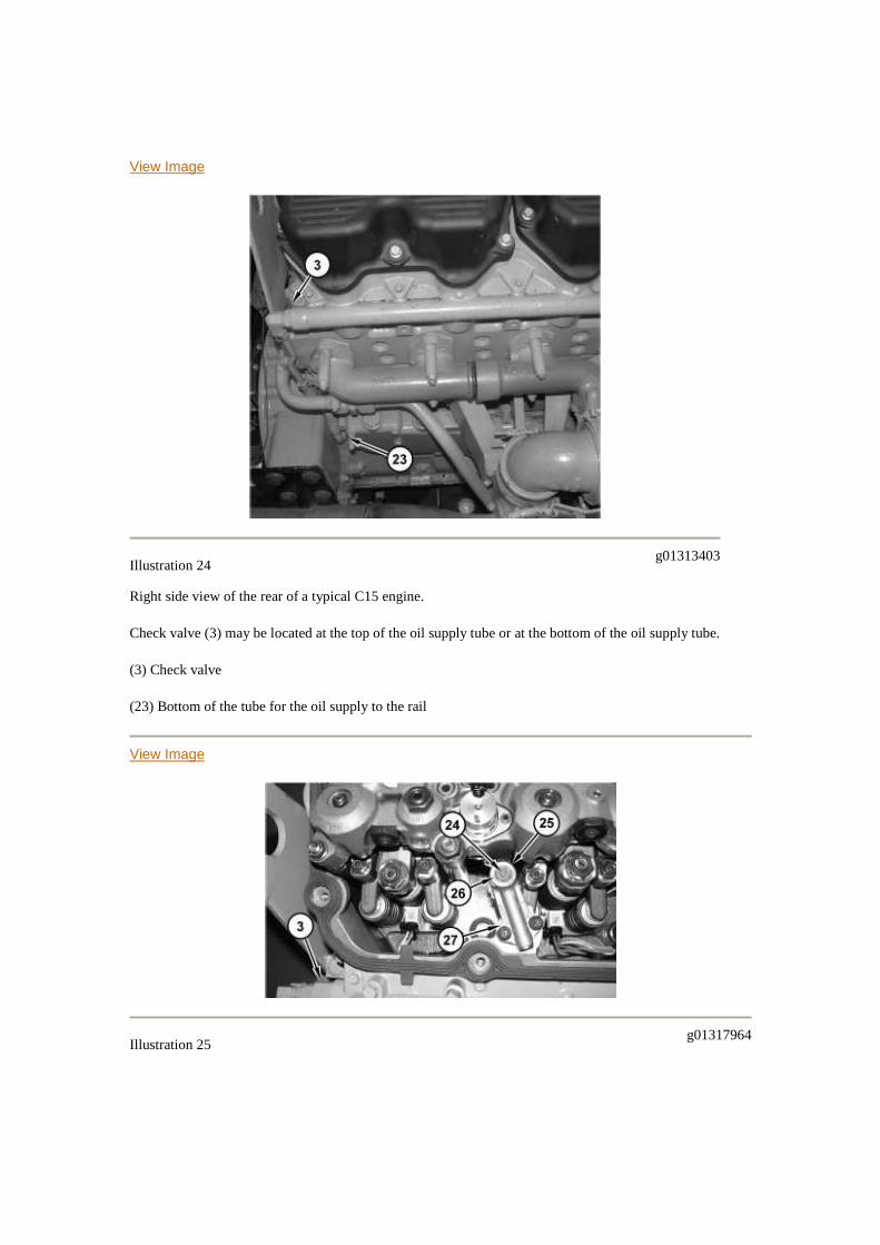
Illustration 14g01313403
Right side view of the rear of a typical C15 engine.
Check valve (3) may be located at the top of the oil supply tube or at the bottom of the oil supply tube.
(3) Check valve
(23) Bottom of the tube for the oil supply to the rail
View Image
Illustration 15g01317964
Top view of the right rear of a typical C15 engine.
Two O-ring seals are installed at location (26) between quill tube (24) and jumper tube (25) . One O-ring
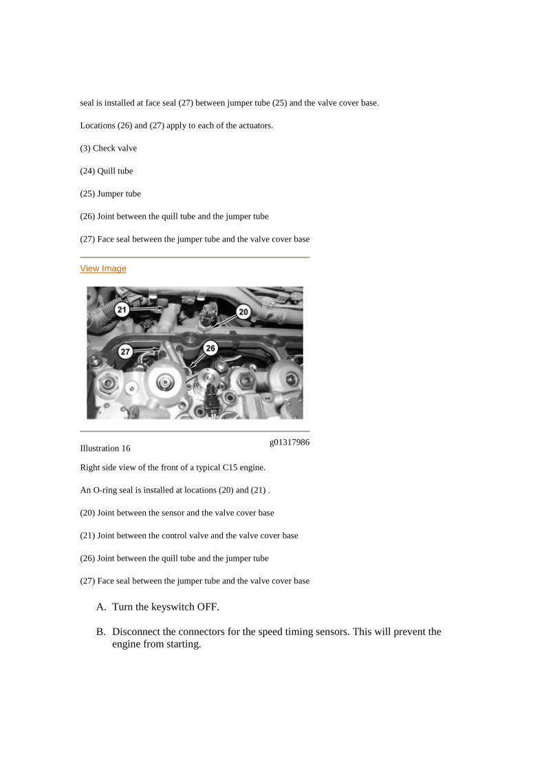
seal is installed at face seal (27) between jumper tube (25) and the valve cover base.
Locations (26) and (27) apply to each of the actuators.
(3) Check valve
(24) Quill tube
(25) Jumper tube
(26) Joint between the quill tube and the jumper tube
(27) Face seal between the jumper tube and the valve cover base
View Image
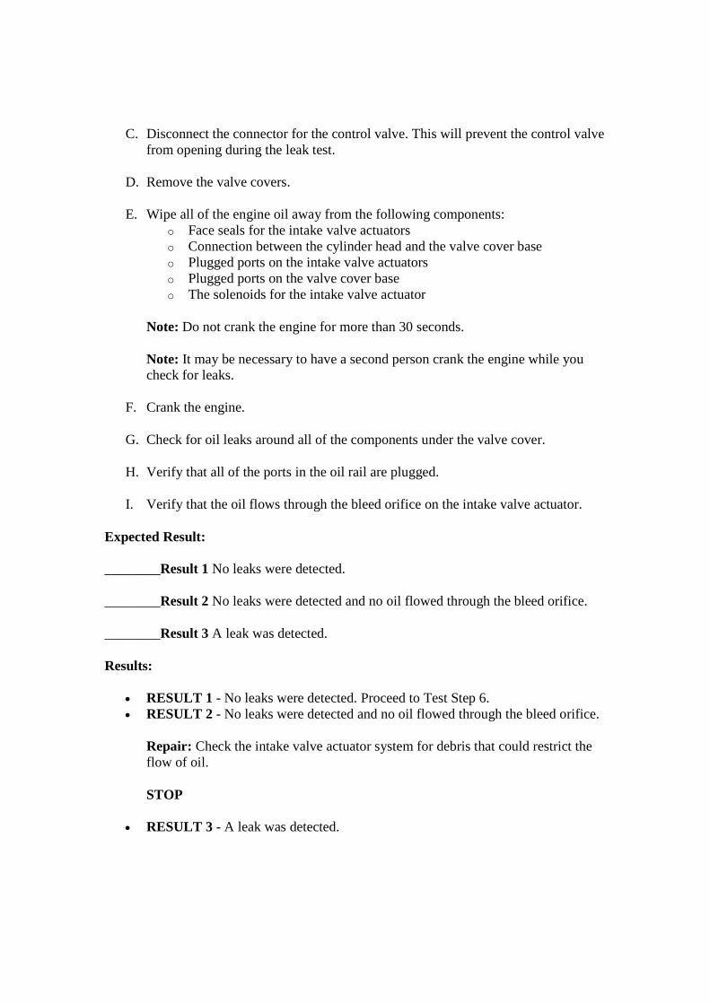
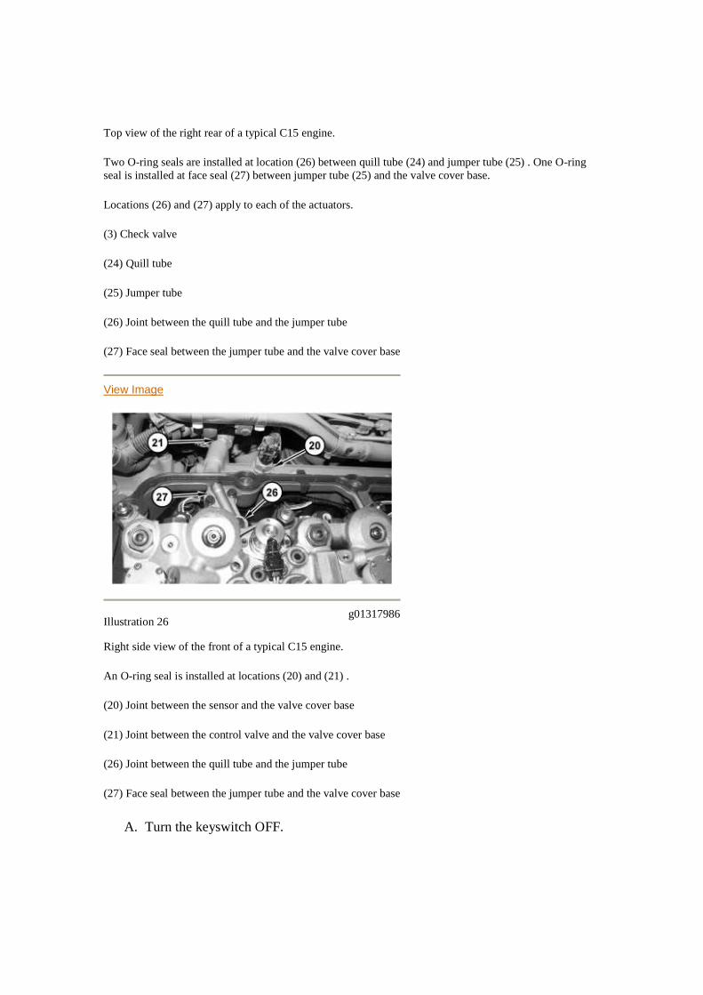
Illustration 16g01317986
Right side view of the front of a typical C15 engine.
An O-ring seal is installed at locations (20) and (21) .
(20) Joint between the sensor and the valve cover base
(21) Joint between the control valve and the valve cover base
(26) Joint between the quill tube and the jumper tube
(27) Face seal between the jumper tube and the valve cover base
A. Turn the keyswitch OFF.
B. Disconnect the connectors for the speed timing sensors. This will prevent theengine from starting.
C. Disconnect the connector for the control valve. This will prevent the control valvefrom opening during the leak test.
D. Remove the valve covers.
E. Wipe all of the engine oil away from the following components:o Face seals for the intake valve actuatorso Connection between the cylinder head and the valve cover baseo Plugged ports on the intake valve actuatorso Plugged ports on the valve cover baseo The solenoids for the intake valve actuator
Note: Do not crank the engine for more than 30 seconds.
Note: It may be necessary to have a second person crank the engine while youcheck for leaks.
F. Crank the engine.
G. Check for oil leaks around all of the components under the valve cover.
H. Verify that all of the ports in the oil rail are plugged.
I. Verify that the oil flows through the bleed orifice on the intake valve actuator.
Expected Result:
________Result 1 No leaks were detected.
________Result 2 No leaks were detected and no oil flowed through the bleed orifice.
________Result 3 A leak was detected.
Results:
RESULT 1 - No leaks were detected. Proceed to Test Step 6. RESULT 2 - No leaks were detected and no oil flowed through the bleed orifice.
Repair: Check the intake valve actuator system for debris that could restrict theflow of oil.
STOP
RESULT 3 - A leak was detected.
Repair: Check the appropriate box that indicates the location of theleak.________ Face seals for the intake valve actuators.________ The intakevalve actuation oil pressure solenoid.________ The sealing joint that is betweenthe cylinder head and the valve cover base.________ Plugged ports on the intakevalve actuators.________ Plugged ports on the the valve cover base.________Intake valve actuators solenoids.Determine the source of the leak and repair theleak. Clear all logged diagnostic codes.Install the valve covers. Connect allelectrical connectors.Start the engine if 283-7 was the only diagnostic code thatwas logged. Run the engine for at least 30 seconds until the engine coolanttemperature is greater than 20 °C (68 °F). If 283-7 does not return, the repair iscomplete.If other diagnostic codes were logged, road test the vehicle. Someproblems will only occur when the engine is under a load. If logged diagnosticcodes do not return, the repair is complete.
Proceed to Test Step 6.
Test Step 6. Check the Check Valve
Note: Do not perform this procedure on engines with serial numbers (S/N: KCA1-160KCB1-508). Assume that the check valve is OK. Proceed to the results.
A. Remove the check valve.
B. Inspect the check valve. Look for debris that could cause the check valve to stick.
List any debris that was found in the check valve. ________
Note: If large amounts of debris are found, determine the source of the debrisbefore continuing with this procedure.
Expected Result:
The check valve is OK.
Results:
OK - The check valve is "OK". Proceed to Test Step 7. Not OK - The check valve is damaged.
Repair: Replace the check valve. Verify that the repair has corrected the problem.If 283-7 was the only diagnostic code that was logged, start the engine and allowthe engine to run for at least 30 seconds once the engine coolant temperature isgreater than 20 °C (68 °F). Verify that the repairs have eliminated the problem. If283-7 does not return, the repair is complete.
If 283-7 returns or if 385-1 returns, proceed to Test Step 7.
If 285-7 through 290-7 returns, proceed to Test Step 8.
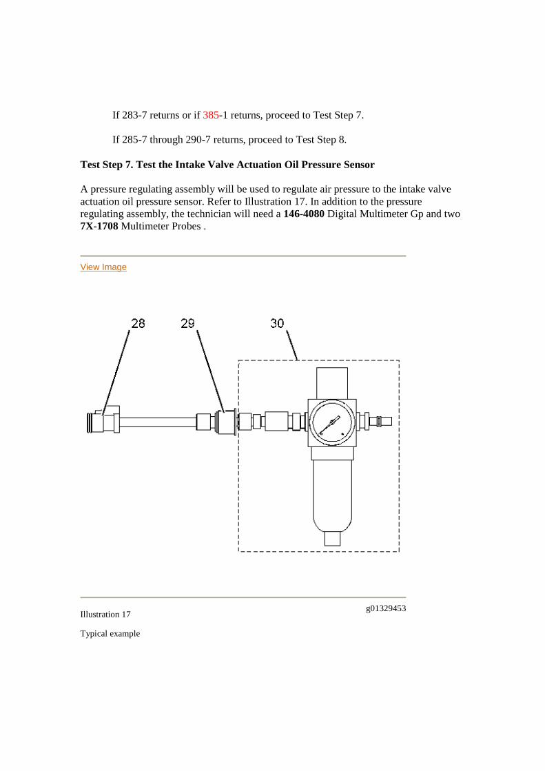
Test Step 7. Test the Intake Valve Actuation Oil Pressure Sensor
A pressure regulating assembly will be used to regulate air pressure to the intake valveactuation oil pressure sensor. Refer to Illustration 17. In addition to the pressureregulating assembly, the technician will need a 146-4080 Digital Multimeter Gp and two7X-1708 Multimeter Probes .
View Image
Illustration 17g01329453
Typical example
(28) Sensor connector
(29) Intake valve actuation oil pressure sensor
(30) Fabricated tool
The fabricated tool consists of the following fittings and components:
5/16 JIC Female to 1/4 JIC Male 1/4 JIC Female Swivel to 1/4 NPT Male 1/4 to 1/4 Male NPT Pressure regulator
Note: The technician is allowed to determine the exact assembly of this tool.
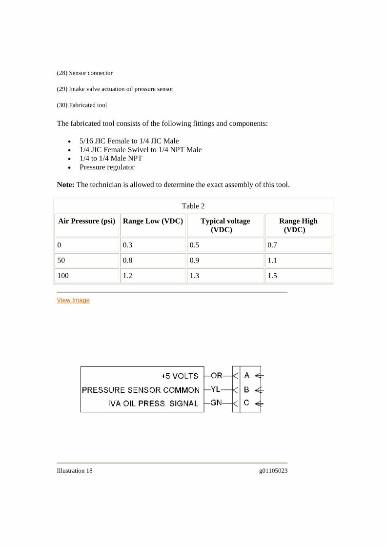
Table 2
Air Pressure (psi) Range Low (VDC) Typical voltage(VDC)
Range High(VDC)
0 0.3 0.5 0.7
50 0.8 0.9 1.1
100 1.2 1.3 1.5
View Image
Illustration 18 g01105023
Intake valve actuation oil pressure sensor
A. Fabricate the above assembly.
B. Turn the keyswitch OFF.
C. Disconnect the connector for the intake valve actuation oil pressure sensor.
D. Remove the intake valve actuation oil pressure sensor from the valve cover base.
Note: If this procedure is used on a C11 or C13 engine the valve cover must beremoved.
E. Install the fittings and the pressure regulator onto the intake valve actuation oilpressure sensor.
F. Connect the connector for the intake valve actuation oil pressure sensor to theengine harness.
Note: Ensure that the air pressure setting is less than 50 psi before applying airpressure onto the test apparatus.
G. Apply shop air pressure to the assembly.
H. Turn the keyswitch ON.
I. Measure the voltage between terminal B and terminal C at the sensor connector.Refer to Illustration 18 for pin locations.
J. Apply the air pressure that is indicated in Table 3 to the intake valve actuation oilpressure sensor. Record the voltage measurements at the different air pressures.
Expected Result:
The voltage measurements are within the ranges listed in Table 3.
Results:
OK - The voltage measurements are within range.
Repair: Start the engine and allow the engine to run for at least 30 seconds oncethe engine coolant temperature is greater than 20 °C (68 °F). If the 283-7 codedoes not return, the repair is complete.
If the 283-7 code returns, proceed to Test Step 8.
If a 385-1 code returns, proceed to Test Step 13.
Not OK - The voltage measurements are not within the given range.
Repair: Replace the intake valve actuation oil pressure sensor. Verify that therepair resolved the problem.
STOP
Test Step 8. Perform the Automatic "Cylinder Cutout Test"
A. Start the engine.
B. Access the "Cylinder Cutout Test" in the "Diagnostic Tests" under the"Diagnostics" menu.
C. Select the "Automatic Cylinder Cutout Test" on Cat ET.
D. Start the test.
Expected Result:
All of the cylinders indicated "OK" during the "Cylinder Cutout Test".
Check the appropriate box in front of the cylinders that indicates "OK".
________ #1 cylinder
________ #2 cylinder
________ #3 cylinder
________ #4 cylinder
________ #5 cylinder
________ #6 cylinder
Results:
OK - Proceed to Test Step 9. Not OK - One or more cylinders failed the "Cylinder Cutout Test".
Repair: Diagnose the problem and then repair the cylinders that failed the"Cylinder Cutout Test" before continuing with this procedure. Clear all loggeddiagnostic codes. Verify that the repair has eliminated the problem in the cylinder.
Proceed to Test Step 9.
Test Step 9. Perform the "Intake Valve Actuator Test"
Note: The "Intake Valve Actuator Test" is not valid until a "Cylinder Cutout Test" hasshown all of the cylinders to be functioning properly.
A. Start the engine. Allow the engine to operate until the coolant temperature is atleast 60 °C (140 °F).
B. Access the "Intake Valve Actuator Test" in the "Diagnostic Tests" under the"Diagnostic" menu.
C. After you adhere to the warnings, start the automatic "Intake Valve ActuatorTest".
Note: The test will cycle two times. Once the test is complete the engine speedwill increase to 2100 rpm for 15 seconds. An "OK" or "Not OK" will be displayedonce the test is complete.
Expected Result:
All cylinders indicate "OK" during the "Intake Valve Actuator Test".
Results:
OK - All cylinders indicate "OK".
Repair: Check the appropriate box in front of the cylinders that indicates"OK".________ #1 cylinder________ #2 cylinder________ #3 cylinder________#4 cylinder________ #5 cylinder________ #6 cylinderWarm the engine until theengine coolant temperature reaches 75 °C (167 °F).Repeat the "Intake ValveActuator Test".
If all cylinders indicate "OK", proceed to Test Step 11.
Not OK - One or more cylinders indicate "Not OK".
Repair: Check the appropriate box in front of the cylinders that indicate "NotOK".________ #1 cylinder________ #2 cylinder________ #3 cylinder________#4 cylinder________ #5 cylinder________ #6 cylinder
Proceed to Test Step 10.
Test Step 10. Check the Lash Settings for the Intake Valve Actuator
A. Turn the keyswitch OFF.
B. Allow the engine to cool.
C. Remove the valve cover(s) from the engine.
D. Check the lash settings for the intake valve actuators. Refer to Testing andAdjusting for the proper procedure.
Expected Result:
The lash settings are within the specification.
Record the initial lash settings for each unit prior to adjustment. Also, record the currentmileage and the mileage of the last lash setting for the intake valve actuators.
________ Current Mileage
________ Mileage at last Adjustment
________ #1
________ #2
________ #3
________ #4
________ #5
________ #6
Results:
OK - The lash settings are within the specification. Proceed to Test Step 11. Not OK - The lash settings are not within the specification.
Repair: Adjust the lash settings. Refer to Testing and Adjusting for the properprocedure. If the mileage between the lash adjustment intervals that are indicatedabove (current mileage minus the mileage of the last adjustment) exceeds therecommended interval, the root cause of the problem could indicate a lack ofmaintenance. Refer to Operation and Maintenance Manual, "Maintenance Interval
Schedule". Verify that the repair eliminates the problem by repeating the "IntakeValve Actuator Test". If all cylinders indicate "OK", return the vehicle to thecustomer.
If one or more cylinders indicate "Not OK" proceed to Test Step 11.
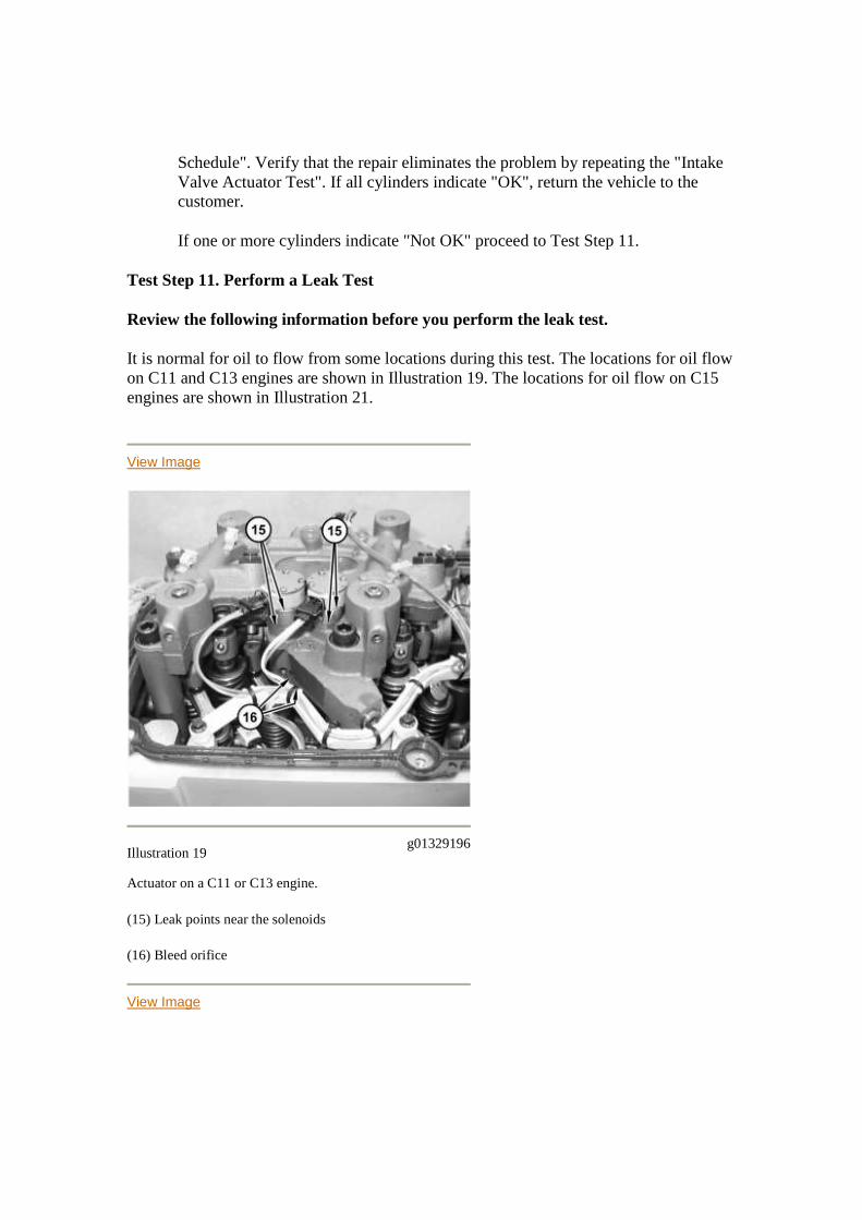
Test Step 11. Perform a Leak Test
Review the following information before you perform the leak test.
It is normal for oil to flow from some locations during this test. The locations for oil flowon C11 and C13 engines are shown in Illustration 19. The locations for oil flow on C15engines are shown in Illustration 21.
View Image
Illustration 19g01329196
Actuator on a C11 or C13 engine.
(15) Leak points near the solenoids
(16) Bleed orifice
View Image
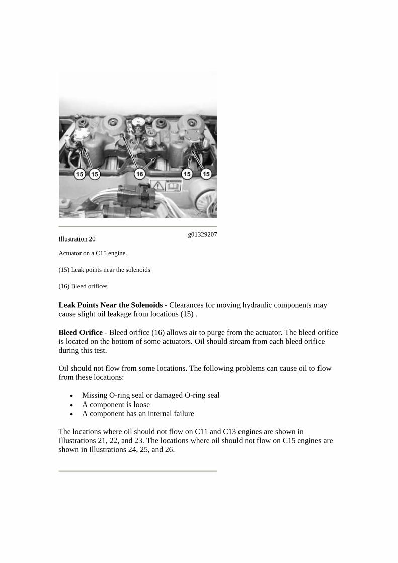
Illustration 20g01329207
Actuator on a C15 engine.
(15) Leak points near the solenoids
(16) Bleed orifices
Leak Points Near the Solenoids - Clearances for moving hydraulic components maycause slight oil leakage from locations (15) .
Bleed Orifice - Bleed orifice (16) allows air to purge from the actuator. The bleed orificeis located on the bottom of some actuators. Oil should stream from each bleed orificeduring this test.
Oil should not flow from some locations. The following problems can cause oil to flowfrom these locations:
Missing O-ring seal or damaged O-ring seal A component is loose A component has an internal failure
The locations where oil should not flow on C11 and C13 engines are shown inIllustrations 21, 22, and 23. The locations where oil should not flow on C15 engines areshown in Illustrations 24, 25, and 26.
View Image
Illustration 21g01318017
Right rear view of a typical C11 and C13 engine
(3) Check valve
View Image
Illustration 22 g01313365
Right rear view of the actuator for cylinders 5 and 6 on a typical C11 and C13 engine.
An O-ring seal is installed at locations (17) , (18) , and (19) . Location (19) applies to each actuator.
(17) Plug threaded into rear of the rail
(18) Joint between the valve cover base and the cylinder head
(19) Joint between the actuator and the cylinder head
View Image
Illustration 23g01313378
Right side view of the actuator for cylinders 1 and 2 on a typical C11 or C13 engine.
An O-ring seal is installed at locations (19) , (20) , (21) , and (22) .
Location (19) applies to each of the actuators.
(19) Joint between the actuator and the cylinder head
(20) Joint between the sensor and the valve cover base
(21) Joint between the control valve and the valve cover base
(22) Plug threaded into the front of the rail
View Image
Illustration 24g01313403
Right side view of the rear of a typical C15 engine.
Check valve (3) may be located at the top of the oil supply tube or at the bottom of the oil supply tube.
(3) Check valve
(23) Bottom of the tube for the oil supply to the rail
View Image
Illustration 25g01317964
Top view of the right rear of a typical C15 engine.
Two O-ring seals are installed at location (26) between quill tube (24) and jumper tube (25) . One O-ringseal is installed at face seal (27) between jumper tube (25) and the valve cover base.
Locations (26) and (27) apply to each of the actuators.
(3) Check valve
(24) Quill tube
(25) Jumper tube
(26) Joint between the quill tube and the jumper tube
(27) Face seal between the jumper tube and the valve cover base
View Image
Illustration 26g01317986
Right side view of the front of a typical C15 engine.
An O-ring seal is installed at locations (20) and (21) .
(20) Joint between the sensor and the valve cover base
(21) Joint between the control valve and the valve cover base
(26) Joint between the quill tube and the jumper tube
(27) Face seal between the jumper tube and the valve cover base
A. Turn the keyswitch OFF.
B. Disconnect the connectors for the speed timing sensors. This will prevent theengine from starting.
C. Disconnect the connector for the control valve. This will prevent the control valvefrom opening during the leak test.
D. Remove the valve covers.
E. Wipe all of the engine oil away from the following components:o Face seals for the intake valve actuatorso Connection between the cylinder head and the valve cover baseo Plugged ports on the intake valve actuatorso Plugged ports on the valve cover baseo The solenoids for the intake valve actuator
Note: Do not crank the engine for more than 30 seconds.
Note: It may be necessary to have a second person crank the engine while youcheck for leaks.
F. Crank the engine.
G. Check for oil leaks around all of the components under the valve cover.
H. Verify that all of the ports in the oil rail are plugged.
I. Verify that the oil flows through the bleed orifice on the intake valve actuator.
Expected Result:
________Result 1 No leaks were detected. Oil flowed through the bleed orifice.
________Result 2 No leaks were detected and no oil flowed through the bleed orifice.
________Result 3 A leak was detected.
Results:
RESULT 1 - No leaks were detected. Oil flowed through the bleed orifice.Proceed to Test Step 12.
RESULT 2 - No leaks were detected and no oil flowed through the bleed orifice.
Repair: Check the intake valve actuator system for debris that could restrict theflow of oil.
STOP
RESULT 3 - A leak was detected.
Repair: Check the appropriate box that indicates the location of theleak.________ Face seals for the intake valve actuators.________ The intakevalve actuation oil pressure solenoid.________ The sealing joint that is betweenthe cylinder head and the valve cover base.________ Plugged ports on the intakevalve actuators.________ Plugged ports on the the valve cover base.________Intake valve actuators solenoids.Determine the source of the leak and repair theleak. Clear all logged diagnostic codes.Install the valve covers. Connect allelectrical connectors.
STOP
Test Step 12. Check the Check Valve
Note: Do not perform this procedure on engines with serial numbers (S/N: KCA1-160KCB1-508). Assume that the check valve is OK. Proceed to the next Test Step.
A. Remove the check valve.
B. Inspect the check valve. Look for debris that could cause the check valve to stick.
List any debris that was found in the check valve. ________
Note: If large amounts of debris are found, determine the source of the debrisbefore continuing with this procedure.
Expected Result:
The check valve is OK.
Results:
OK - The check valve is OK. Proceed to Test Step 13. Not OK - The check valve is damaged.
Repair: Replace the check valve. Road test the vehicle. Verify that the repaireliminates the problem.
If the repair does not eliminate the problem, proceed to Test Step 13.
Test Step 13. Inspect the Hardware
Inspect the suspect intake valve actuator unit.
A. Remove the suspect intake valve actuator.
B. Inspect the face seal for damage.
C. Inspect the intake valve actuator for damage.
D. Check for debris in the intake valve actuator assembly. Do not disassemble theunit.
Expected Result:
The intake valve actuators are free of debris and the face seals are OK.
Results:
OK - There is no debris in the assembly and the face seals are not damaged.
Repair: Replace only the suspect intake valve actuator assembly. Refer to Testingand Adjusting for the proper procedure.Verify that the repair eliminates theproblem by performing the "Intake Valve Actuator Test". Road test the vehicle.Some problems will only occur when the engine is under a load. Always road testthe vehicle under a load before returning the vehicle to the customer.
STOP
Not OK - There is debris in the assembly or there is a damaged face seal.
Repair: List any debris that was found in the assembly. ________Replace anydamaged face seals. Remove any debris that is found in the intake valve actuatorassembly. If the intake valve actuator failed the "Intake Valve Actuator Test",verify that the repair eliminates the problem by performing another "Intake ValveActuator Test".If the intake valve actuator did not fail the "Intake Valve ActuatorTest", perform a road test. Some problems will only occur when the engine isunder a load.
STOP