Embed Size (px)
Citation preview

i1
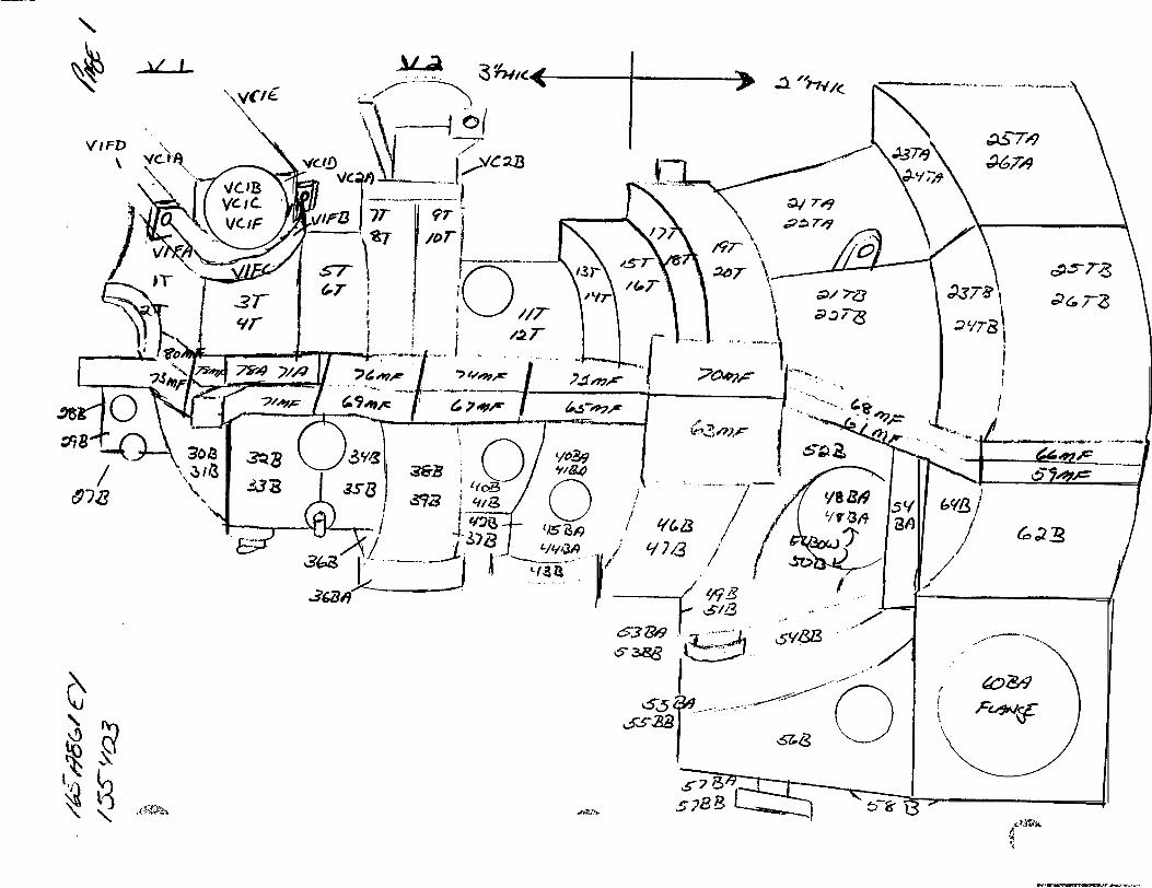
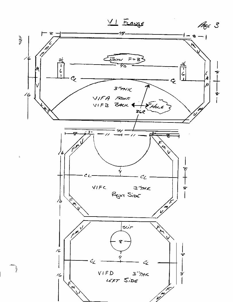
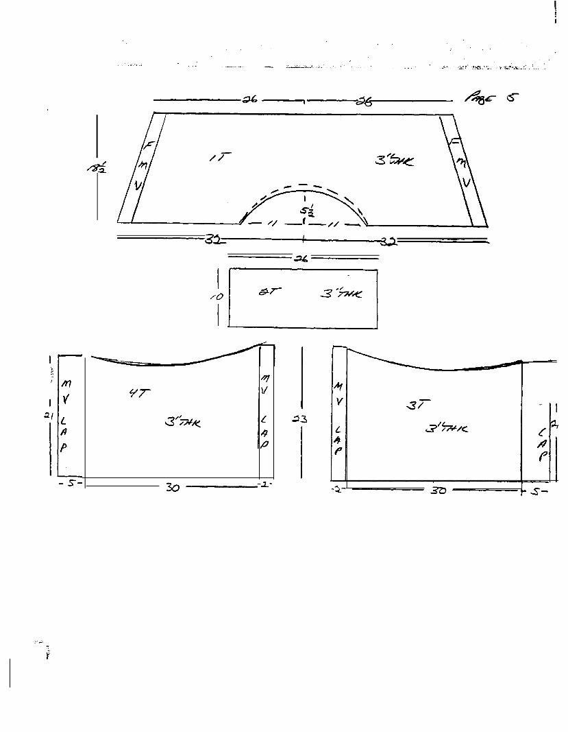
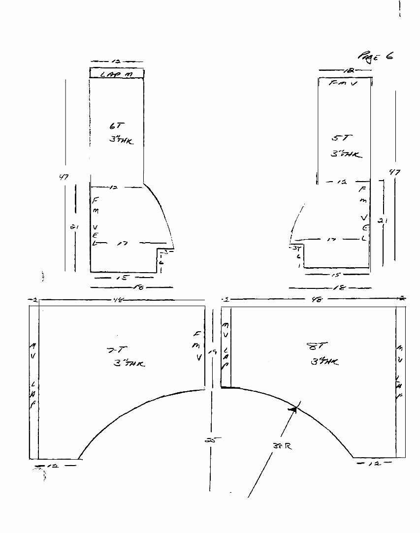
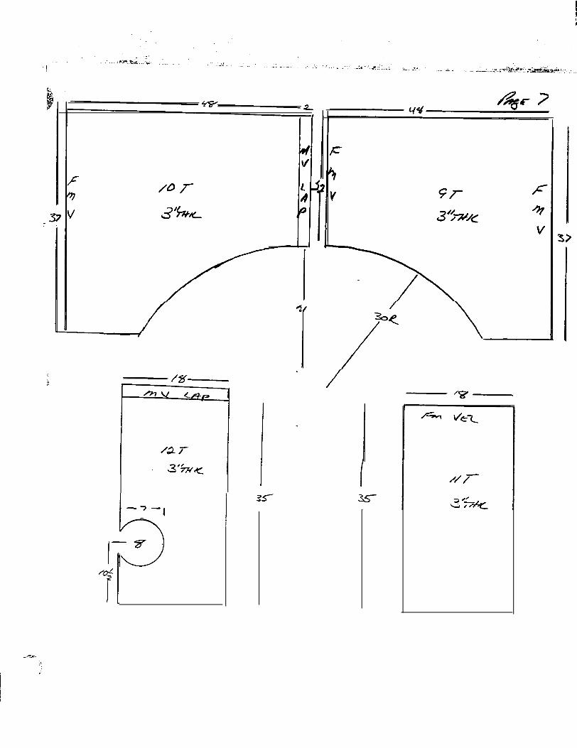
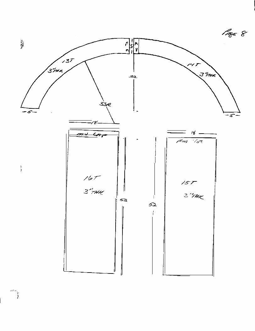
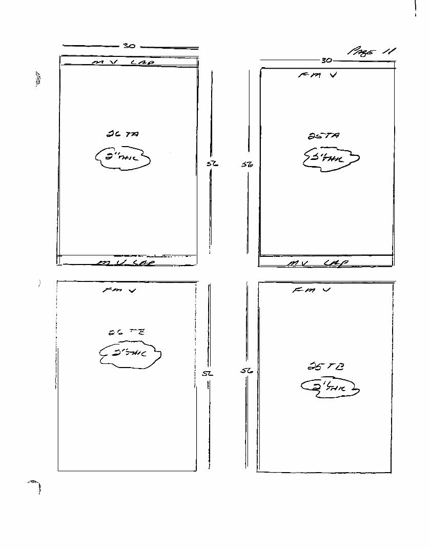
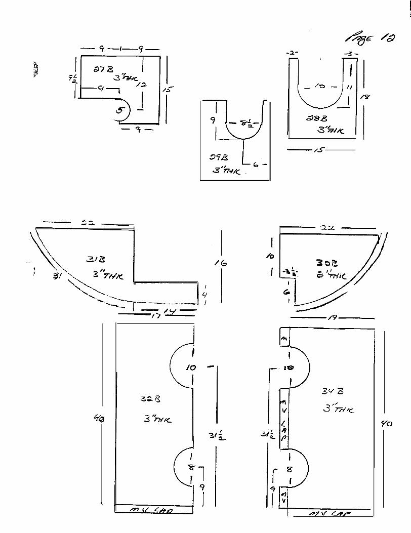
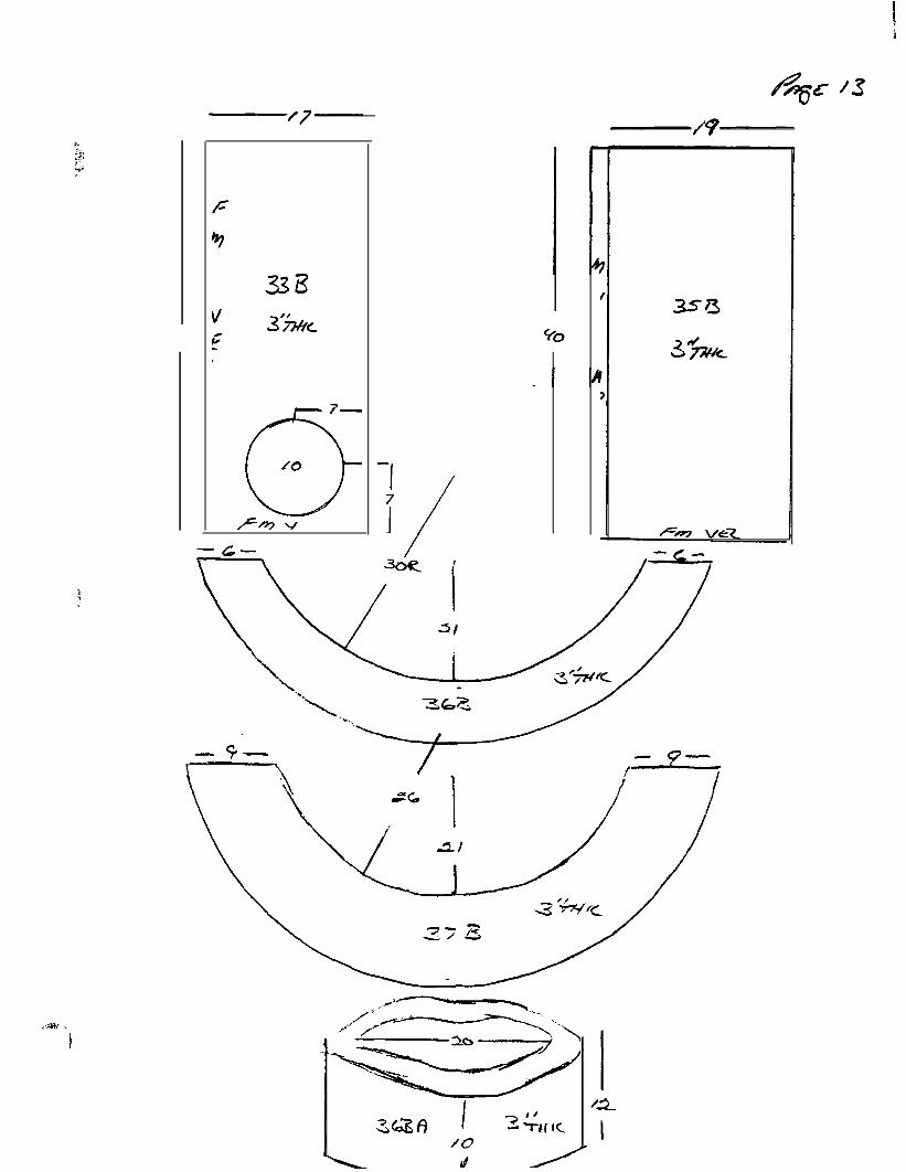
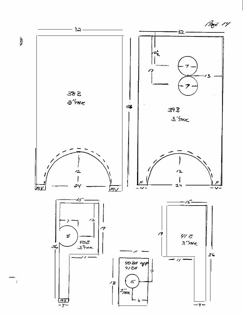
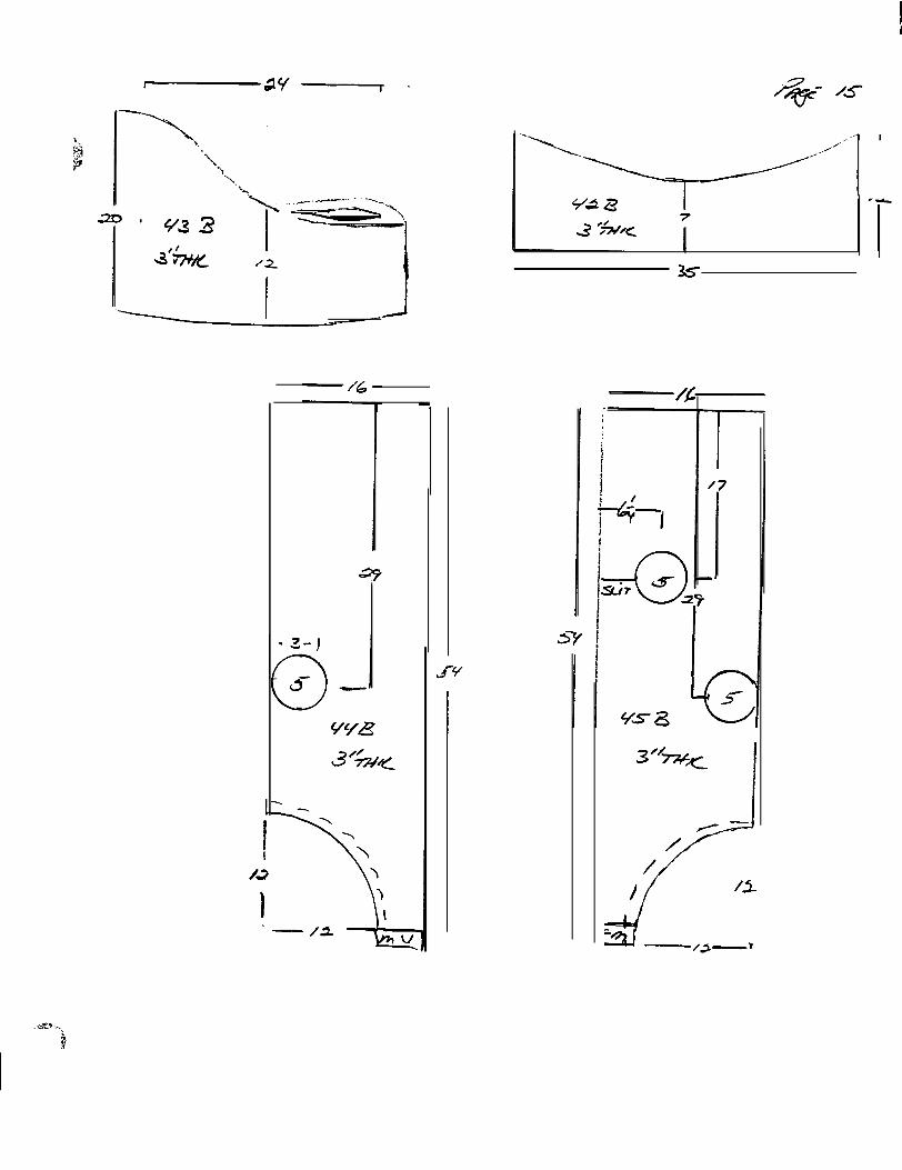
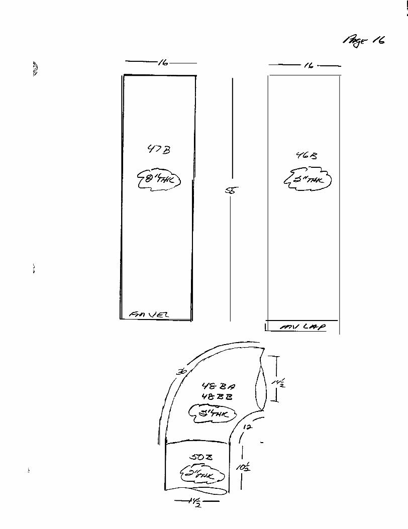
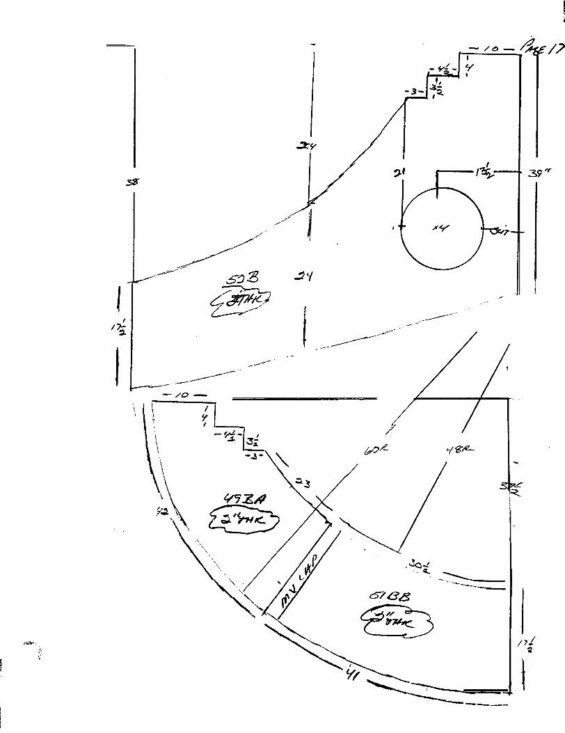
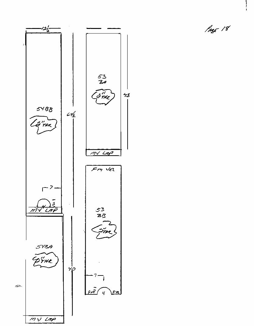
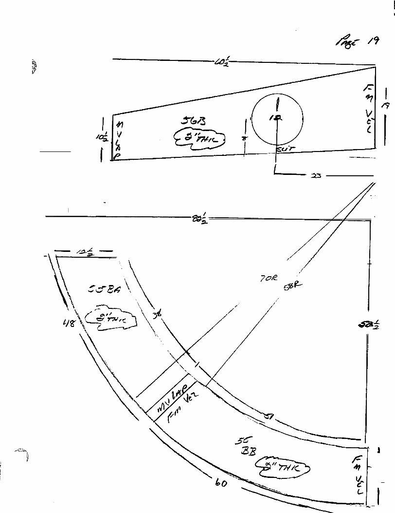
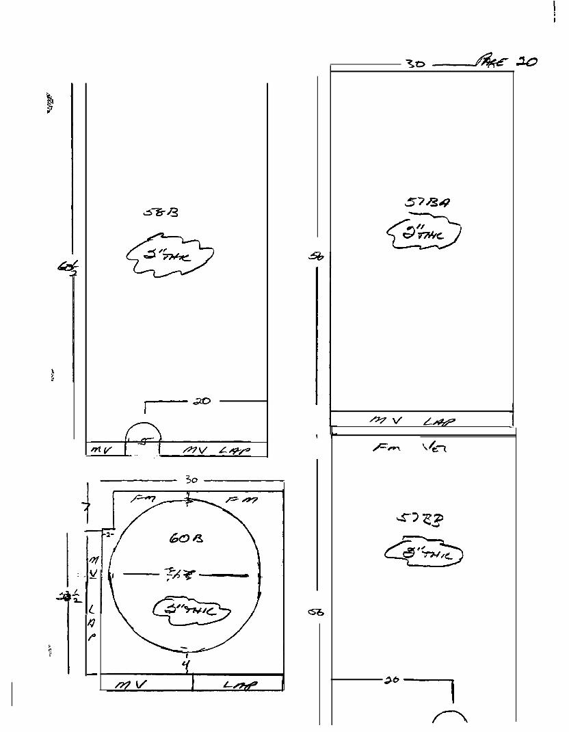
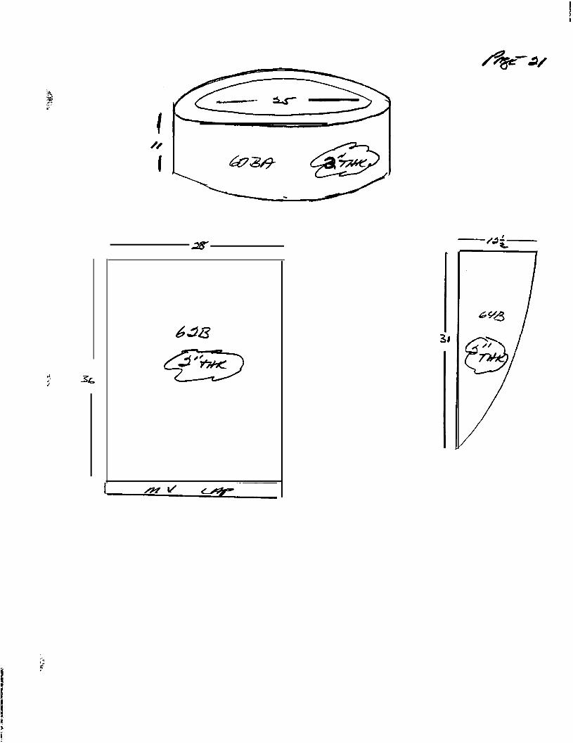
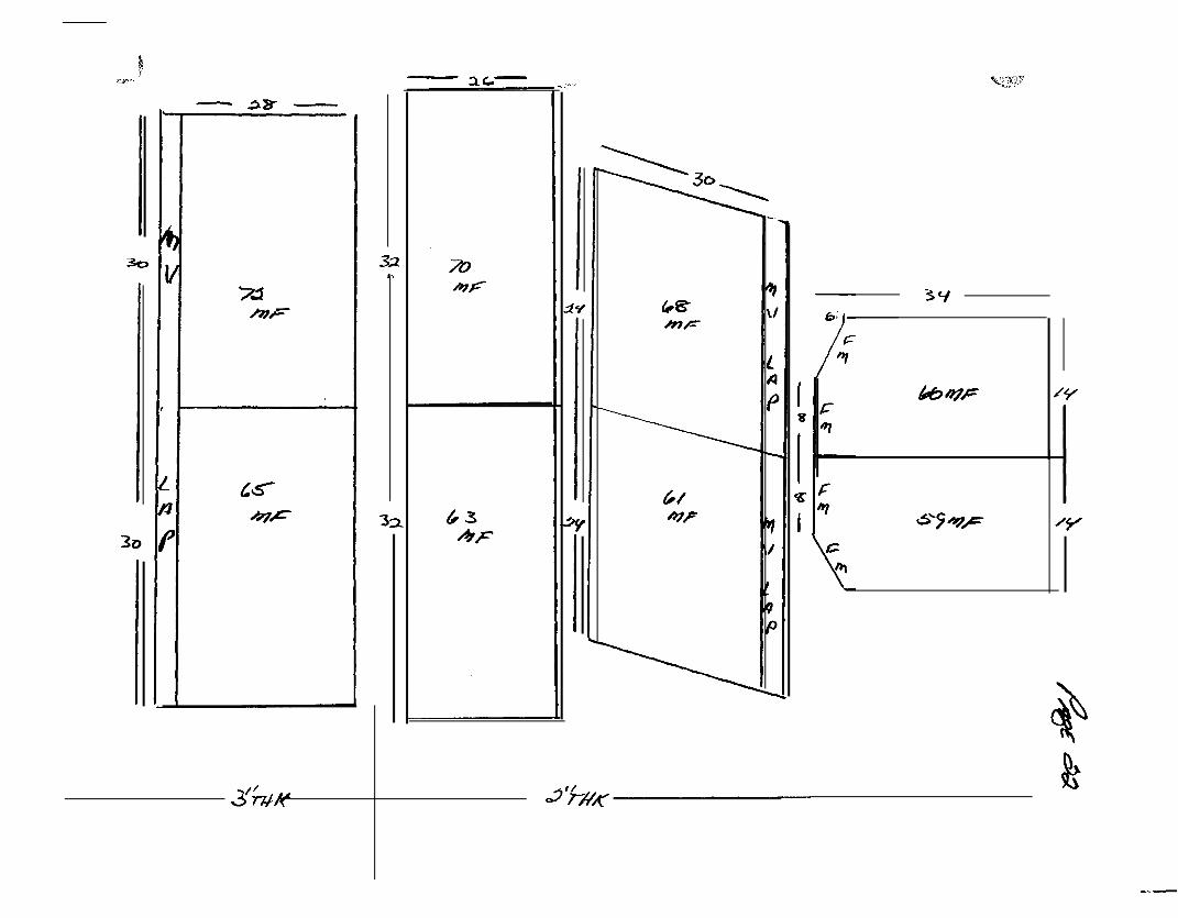
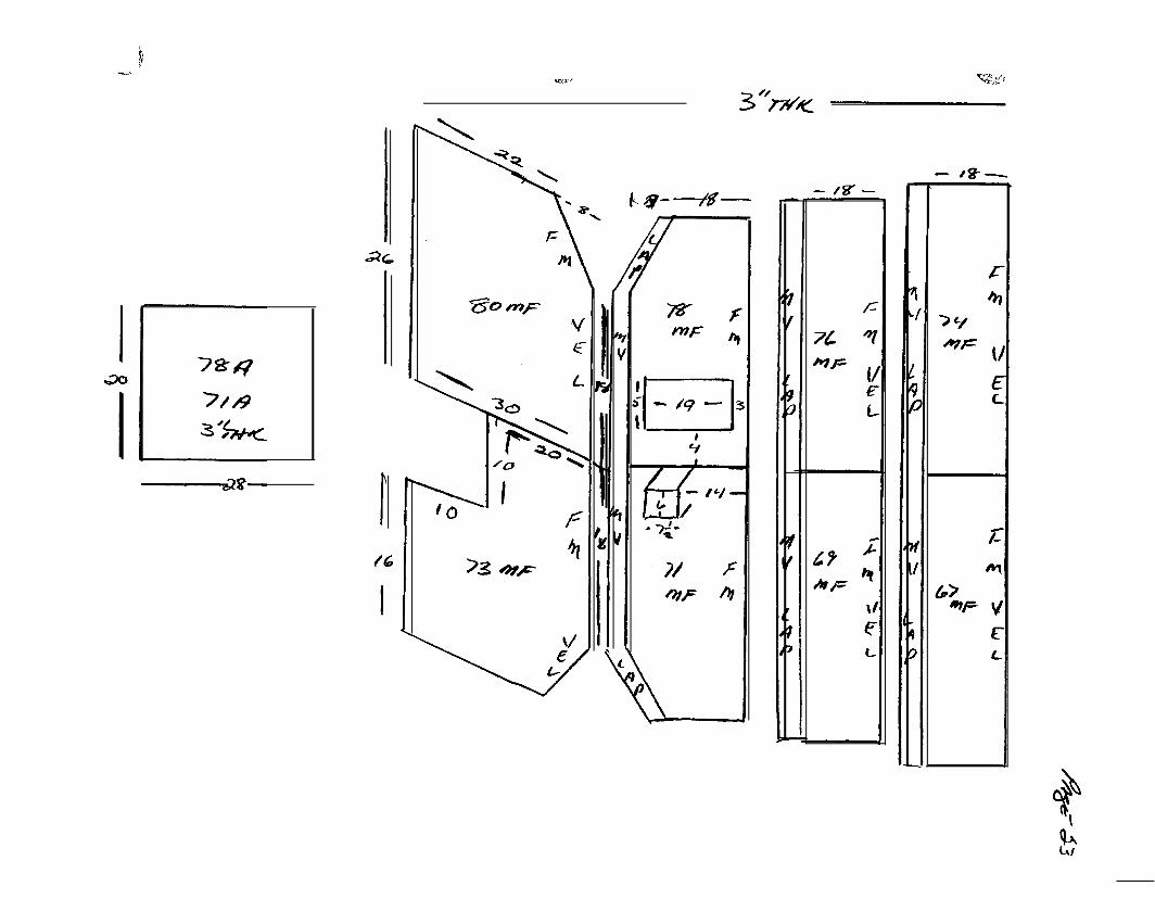
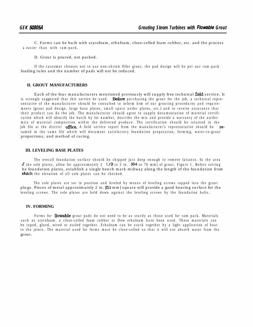
INSULATION SKETCHESTURBINE 155403GE DRAWING 165A861 EY-1
THE CLAREMONT SALES CORPORAlION174 State Street, P.O. Box 952Msrtden, CT 06450 U.S.A.Tel. (203) 238.2334 or l-800-222-4448Fax (203) 2389329
INSTRUCTION PAGE
A. Looking at turbine (FRONT TO REAR)
RIGHT SIDE EVEN NUMBERLEFT SIDE ODD NUMBER1 . Valve chest V-l prefu top
2. Steam chest H. P. end top T-prefix T- 1 - T- 16.3. Steam chest HP end bottom B-prefix B-17 - B-28.4. Horizontal joint maid flange. Start from exhaust forward MF29 -
MJ536 - Same as steam chest EVEN NUMBER RIGHT SIDE -ODD NUMBER LEFT SIDE.
RECOMMENDATIONS;
Start with bottom pieces wired secured in place. Then go to top valve chestand top pieces. Working to exhaust section (NO INSULATION). Last mainflange (HORZ. JOINT) starting from exhaust working forward.
/
yI
_- .
.-.. _

I I 1 I
I
.._ ,. - _-_.
1
Y-7
i
i
I Y7
c
47- I5
I-27.,-li
.
I
I
I55221I

3sa

5
---- _L-_. . . . -.-w . ..-rC-
I-u9I - -2-k!=-I
IirIO -
-/s
q--
33z3’k
7-
Fo
/o
rr;,v
-17
Ji
.
I4/-
/9
- // -36
-Y-
r7 -
--..-
-23. _
I
\\
4P
-
-&--a&-
31

INSTRUCTIONSFOR
INSTALLAnON & MAINTEN~CE
OF
KINGSBURYPIVOTED SHOE JOURNAL BEARING
@INGSBURY INC.
10385 DRUKMOND ROAD, PHILADELPHIA, PA 19154TEW(/TWX 710-670-1887 (KINGSBURYA PHA)
I.
BXF. No.
b .-LKPSJBJM
II
C O N T E N T S
PageN o .
CRAPTER 1 - GENERAL INFORMATION
1.1 INTRODUCTION ............................... 1
1.2 GENERAL DESCRIPTION ........................ 1
1.3 DETAILED DESCRIPTION ....................... 1
CRAPTER 2 - INSTALLATION
2.1 DISASSEMBLY, CLEANING t INSPECTION . . . . . . . . . . 3
2.2 ASSEMBLY . . . . . . . . . . . . . . . . . . . . . . . . . . . . . . . . . . . 4
CRAPTRR 3 - OPERATING INBTRUCTIONS
3.1 LUBRICATING & COOLING ...................... 5
3.2 GRADE OF OIL ............................... 5
3.3 OPERATION .................................. 5
CEAPTER 4 - CARE & MAINTENANCE
4.1 TROUBLESHOOTING ............................ 6
4.2 INSPECTION & REPLACEMENT ................... 6
4.3 REPAIRS C SERVICE .......................... 7
i

CRAP!PERl- GENERAL INFORKATION
1.1 INTRODUCTION
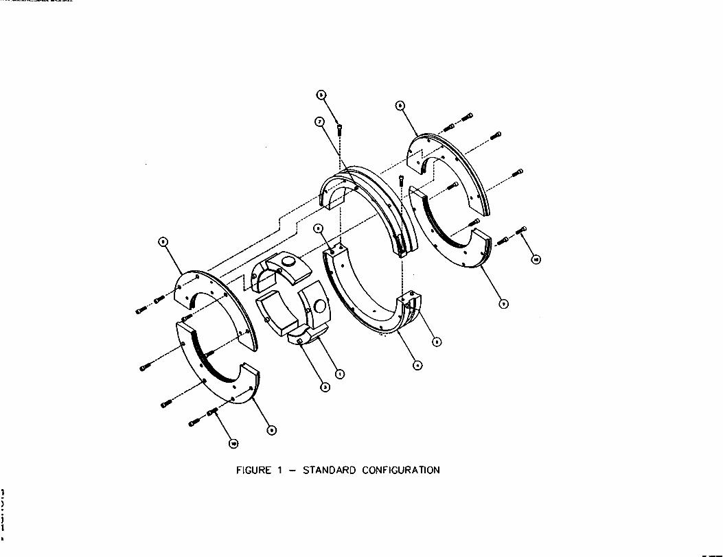
a. The general construction of the pivoted shoebearing is shown in expioded view, Figure 1.
journalFigure 2
presents the specific assembly drawing of the bearing(s)supplied on this order.
1.2 GENERAL DESCRIPTION - Figure 1
a. The pivoted shoe journal bearing is divided into a numberof sections called shoes, which are enclosed in a splitouter shell called an aligning ring. The face of each shoeis coated with babbitt, a soft metal. The rear of eachshoe is radiused both axially and circumferentially, and issupported in the bore of the aligning ring.
b. In operation, each shoe is free to pivot slightly inreference to the journal surface. This freedom allows oiladhering to the journal to form wedge-shaped films betweenthe shoes and the journal. These films, thickest at theleading edge and tapering toward the trailing edge, areautomatically self-renewing as long as the shaft rotatesand lubrication is provided.
c. Shoe retaining plates prevent excessive leakage out of thejournal bearing cavity.
1.3 DETAILED DESCRIPTION - Figure 1
a. The matchmarked halves of the aligning ring (4) are securedtogether with self-locking joint screws (5). Joint dowels(6) ensure correct assembly.
b. The shoes (1, 2) are positioned axially by shoe retainingplates (9), which in turn are positioned on the aligningring by dowels (7). The shoe retaining plates are securedto the aligning ring by screws (10).
C . Shoe (2) refers to an instrumented shoe, one which isdrilled to accept a temperature detector (if supplied). Ithas a definite location in the assembly, which is dependentupon the direction of shaft rotation. (See Figure 2). Thenon-instrumented shoes (1) are interchangeable.
d. The shoes are restrained from angular displacement aroundthe shaft by stop pins (3) which engage holes in theretaining plates (9).

e. Rotation of the bearing assembly within the housing isprevented by an anti-rotation dowel (8) located in eitherthe upper or lower half of the aligning ring. The dowelfits into a milled slot in the housing near the joint.
f. Oil is supplied to the annulus on the outer diameter of thealigning ring (4). From the annulus the oil travelsthrough five radially drilled holes, entering the aligningring (4) bore between shoes. The oil is then picked up bythe journal and is drawn into the wedge-shaped films thatexist between the journal and shoes. Oil exits the bearingthrough the clearance between the shaft and shoe retainingplates (9).
2
CHAPTER2- INSTALLATION
2.1 DISASSEMBLY, CLEANING b INSPECTION - Figure 1
d. Bearings are customarily shipped assembled. All parts havebeen slushed with a neutral waterproof coating and thebearing surfaces are carefully protected from mechanicaldamage and corrosion. Subsequent damage may occur ifspecial precautions are not taken during inspection andinstallation.
b. Remove packaging material from each bearing assembly andlay assembly on a clean, flat surface.
c. Remove aligning ring joint screwsassembled halves.
(5) and separate
d. Remove the shoe retaining plate screws (10) from theretaining plates on one side of the assembled halves.Select the side that the instrumented shoe leads exit, ifapplicable.
e. Remove retaining plate halves (9) and lift out journalshoes (1, 2). Be careful not to damage the lead(s) of theinstrumented shoe(s).
f. Turn aligning ring over and remove the retaining platescrews (10) and the shoe retaining plate halves (9).
g. Remove all anti-rust coatings with a mixture of oil andsolvent, or kerosene.cleaning.
Use lint free rags or cloth for
CAUTIONA poorly cleaned bearing will score and wear outrapidly. A bearing surface is not clean until awhite cloth wiped over it shows no soil.
h. Inspect the parts after cleaning. Remove any raised metalon the babbitt surfaces with a scraper.
3
2.2 ASSEMBLY - Figure 1
a. Lay aligning ring (4) on a clean, smooth, flat surface andassemble halves with joint screws (5). Observe matchmarksto ensure proper mating.
b. Install shoe retaining plate (9). Aligning ring locatingpin (7), must enter proper hole in retaining plate.Observe retaining plate matchmarks.
c. Install and stake eight shoe retaining plate screws (10).
d. Turn aligning ring assembly over and install shoes (1,2).Be sure shoe stop pins enter holes in shoe retaining plate.Shoe (2) has a definite location if supplied.
e. Install shoe retaining plate (9) with aligning ringlocating dowels (6) and shoe stop pins (3) entering properholes. Carefully feed instrument leads through theretaining plate (9) before securing (if applicable).
f. Install and stake eight shoe retaining plate screws (10) ineach assembly.
9= Gently push on each shoe to ensure they are free to move.
h. Remove 'aligning ring joint screws (5) and split bearinginto halves.
i. Lubricate shaft journal area with oil.
j- With the shaft positioned slightly above its operatingposition, set the lower half of the bearing assembly on thejournal. Rotate the lower half until it is flush with thehousing joints. If the anti-rotation key is in the lowerbearing assembly, make sure it is seated.
k. Place upper half of the aligning ring shoe assembly overthe lower half assembly and install aligning ring jointscrews (5).
1. Make sure anti-rotation dowel is positioned, lower shaft,and pour oil over assembly.
4
CRAPl'ER3 - OPERATING INSTRUCTIONS
3.1 LUBRICATING f COOLING
a. These bearings are intended to be lubricated from the mainoil system. The rate of oil circulation should keep theoutlet temperature within 25-30*F above the inlet.
b. Control oil flow by throttling or using orifice plugs onthe oil inlet only.is negligible.
The pressure drop through the bearing
3.2 GRADE OF OI&
a. Use the correct viscosity oil. The thrust bearing has beendesigned to use the same oil as the rest of the machinery.
b. Changing to an lighter oil than originally intended maycause the lubricating films to become dangerously thin;heavier oil will increase friction needlessly.
c. Oil must be clean and free from grit or other abrasivesubstances. Fine grit has a scouring action, and dirty orold oil may cause corrosion or sludge.
3.3 OPERATION
a.
b.
The bearing surfaces, when running, areseparated by oil.
completelyThere is practically no wear and,
therefore, no adjustment is provided. As a rule, theoriginal solid dull grey appearance of the bearing shoesremains the same after years of service. This can beexpected if the bearing is clean when installed, and issupplied clean, cool oil of proper viscosity.
Oil flow through the bearings must be established prior toshaft rotation.
5
CHAPTER 4 -CARE ANDKAINTENAWCE
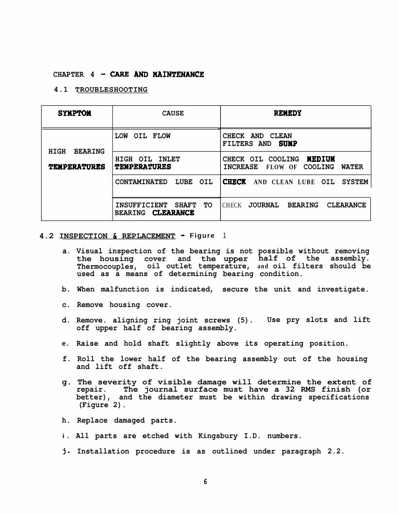
4.1 TROUBLESHOOTING
SYNPTOH CAUSE
LOW OIL FLOW
HIGH BEARINGHIGH OIL INLET
TEWPERATURES TEXPERATURES
CONTAMINATED LUBE OIL
CHECK AND CLEANFILTERS AND SUWP
CHECK OIL COOLING KEDIUHINCREASE FLOW OF COOLING WATER
CRECK AND CLEAN LUBE OIL SYSTEM
INSUFFICIENT SHAFT TOBEARING CLEARANCE
CHECK JOURNAL BEARING CLEARANCE
4.2 INSPECTION C REPLACEMENT - Figure 1
REWEDY
a. Visual inspection of the bearing is not possible without removingthe housing cover and the upper half of the assembly.Thermocouples, oil outlet temperature, and oil filters should beused as a means of determining bearing condition.
b. When malfunction is indicated, secure the unit and investigate.
c. Remove housing cover.
d. Remove. aligning ring joint screws (5). Use pry slots and liftoff upper half of bearing assembly.
e. Raise and hold shaft slightly above its operating position.
f. Roll the lower half of the bearing assembly out of the housingand lift off shaft.
g. The severity of visible damage will determine the extent ofrepair. The journal surface must have a 32 RMS finish (orbetter), and the diameter must be within drawing specifications(Figure 2).
h. Replace damaged parts.
i . All parts are etched with Kingsbury I.D. numbers.
j. Installation procedure is as outlined under paragraph 2.2.
6

4 . 3 REPAIRS AND SERVICE
a. Prompt service is available from:
Kingsbury, Inc.Repair and Service Division3615 Davisville RoadHatboro, Pennsylvania, USA 19040
Phone: 215/956-0565FAX: 215/956-9027
7
G E K 50805ARevision A, June i978Refonnaffed, ocfofw 1990
GE Industrial & Power System..,
Grouting Steam ‘lkbines With Flowable Grout
I. GENERAL
The sole plates which support steam turbines and generators are commonly supported by groutpads while being aligned. Final (filler) grout is later poured between the pads to fill the voids. This groutis supplied by the owner or his contractor and it is his responsibility to provide adequate materials andprocedures to assure grout integrity and dimensional stability. The object is to maintain alignment andsolid support for many years. Though General Electric does not supply grout, the grouting methodsstrongly interface the foundation plate design. For this reason, we make suggestions for grouting proce-dures based on our experience and limited tests.
Sole plates are supported by pads and have provisions for grout plugs which project from the hot.tom of the plate. These plugs provide area for horizontal loading as well as a mounting for leveling screwsGrout pads are located to clear these plugs and the foundation bolts, to allow the final grout to flow underthe plate and completely surround the plugs.
The most common practice for placing pads to provide bearing surface and load carrying abilityhas been to ram-pack grout pads under foundations plates. More recent experience with prepackaged,nonshrink, flowable grout has been favorable and the following suggestions regarding its use are offeredas an alternate to the ram-pack procedure.
Tests and field experience indicate that the following grouts furnish good results:
l Five Star l Unisorb V-l
l Masterbuilders 713 l Sauerisen F-100
If the customer elects to use flowable grout for the grout pads, changes to past grouting proce-dures are described below:
A. Flowable grout must also be used for final (or filler) grouting. This means that the final groutwill carry vertical load in addition to anchoring the plates horizontally as before.
B. Since the final grout will carry vertical load, the number of grout pads will be greatly reduced.The pad area will be sufficient to carry the weight of the turbine parts during installation. Loading whichwill occur during operation (vacuum load, emergency operating loads, etc.) will be carried by both thepads and the final grout.
These instnr~ans do not purport to cover all details or vat&&s in equ@nent nor to ptuvi& foreverypossibletwn&@?ncy to bs met in connection with bNNation, open&ion or maintsnance. Should further Information be dssimd orLshouldpatticu&prvbiems arke which are not coveted sufflchWy for the purchaser’s putposes the mattershouhibetstknvd to ths GE Company. h
GEK 50805A Grouting Steam Turbines with Flowable Grout
C. Forms can be built with styrofoam, ethafoam, close-celled foam rubber, etc. and the process5 easier than with ram-pack.
D. Grout is poured, not packed.
If the customer chooses not to use non-shrink filler grout, the pad design will be per our ram-packloading rules and the number of pads will not be reduced.
II. GROUT MANUFACTURERS
Each of the four manufacturers mentioned previously will supply free technical Beld service. Itis strongly suggested that this service be used. Before purchasing the grout for the job, a technical repre-sentative of the manufacturer should be consulted to inform him of our grouting procedures and require-ments (grout pad design, large base plates, small space under plates, etc.) and to receive assurance thattheir product can do the job. The manufacturer should agree to supply documentation of material certifi-cation which will identify the batch by lot number, describe the mix and provide a warranty of the unifor-mity of material composition within the delivered produce. The certification should be retained in thejob file at the district ofhce. A field service report from the manufacturer’s representative should be re-tamed in the same file which will document satisfactory foundation preparation, forming, water-to-groutproportions, and method of curing.
III. LEVELING BASE PLATES
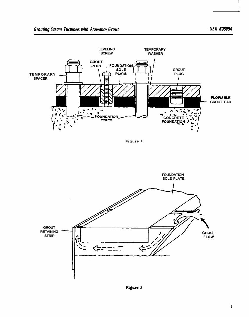
The overall foundation surface should be chipped just deep enough to remove laitance. In the areaIf the sole plates, allow for approximately 2 l/2 to 3 in. [64 to 76 mm] of grout, Figure 1. Before settinghe foundation plates, establish a single bench mark midway along the length of the foundation fromwhich the elevation of all sole plates can be checked.
The sole plates are set in position and leveled by means of leveling screws tapped into the groutplugs. Pieces of metal approximately 2 in. [51 mm] square will provide a good bearing surface for theleveling screws. The sole plates are held down against the leveling screws by the foundation bolts.
IV. FORMING
Forms for flowable grout pads do not need to be as sturdy as those used for ram pack. Materialssuch as styrofoam. a close-celled foam rubber or Dow ethafoam have been used. These materials canbe taped, glued, wired or nailed together. Ethafoam can be stuck together by a light application of heatto the joints. The material used for forms must be close-celled so that it will not absorb water from thegrout.
Grouting Steam Turbines with Flowable Grout GEK 508054
LEVELING TEMPORARYSCREW WASHER
GROUTRETAINING
STRIP
GROUTPLUG
I I I ITEMPORARY -
SPACER
BOLTS CONCRETE $7FOUNDAqO,N . o .
. r*
F i g u r e 1
FOUNDATIONSOLE PLATE
FLOWABLEGROUT PAD
Figure 2
3
GEK 50805A Grouting Steam Turbines with Flo wable Grout
Forms can be built under the foundation plates after they are leveled or can be built before theklates are set and compressed slightly by the foundation plate during the leveling process. In either case,he forms must be tight and make a good seal with the plate and the foundation. Openings between the
forms and foundation must be sealed to prevent grout leakage. A stiff, mortar consistency grout or dux-seal works well for this purpose. If grout leaks from the form it may slump away from the plate and con-tact will be lost.
Forms similar to that shown in Figure 2 work best on LP hood and generator base plates. Notethat the grout retaining strip can be used as part of the form. The outside end of the grout pad form musthave a “head” or ‘riser” to pour the grout into. The slanted end of the form aids the flow of the grout andhelps prevent the formation of atr bubbles while pouring.
Large foundation plates such as under standards or hood extensions require “dead end” formsfor grout pads. Because these forms can be up to 30 in. (76 mm] long, it may be easier to build and placethe forms, then lower the foundation plate over them, compressing forms slightly.
V. POURING
The area where the grout pads will bond to the foundation must be kept saturated for approxi-mately 24 hours before the grout is poured. This pm-wetting period may vary depending on the recom-mendation of the grout manufacturer. Before the grout is placed all excess water must be removed fromthe foundation surface.
Grout must be mixed following the instructions of the manufacturer and preferably with the assis-tance of the manufacturer’s technical representative. Only small batches of grout should be mixed: no
tore than can be placed in the working time available before the grout begins to stiffen. This time willu-y depending on the temperature and water content of the brand of grout used.
The small pads around the LP hoods and generators can simply be poured. The longer pads understandards are filled best by placing grout first at the dead end of the form and working toward the openend to prevent entrapment of air. This can be done by attaching a large flexible hose, such as a 3” 176mm] fire hose, to the bottom of a 4 or 5 gallon 115 or 19 litre] can, pouring the grout into the can andfeeding grout to the end of the form withdrawing the hose as the pad is fi l led. To stop the flow, the hoseis simply pinched shut. The level of the grout in the can should not be allowed to go below the hose con-nection or air may be trapped in the hose when the can is refilled.
If many grout pads are to be fil led at one time, it may be economical to use a grout pump. Othermethods may be equally suitable. Consult the grout manufacturer.
VI. TEST SAMPLES
Samples of the grout mix should be cast into standard test cubes, cured in the same manner asthe grout pads and tested for strength. Final compressive strength should be at least 5000 psi [34.5 MPa]I352 kg/cm2].
I 4

Grouting S&am Turbines with Flowable Grout GEK508054
VII. CURING
Again, preferred methods of curing may vary slightly depending on the grout manufacturer. Gen-erally the grout will cure satisfactorily if the exposed areas are covered with wet rags and plastic to pre-vent evaporation of the water in the grout. The rags and exposed grout should be kept wet during theentire curing process.
After the grout has become very ffrm but not hard, the grout ‘risers” around the edge of the platesare to be cut off. This will leave a neat pad under the plate and prevent the possibility of the grout grippingthe side of the plate. If the risers were left in place they could hinder the later removal of the base platesfor inspection of the pads.
After the risers are cut off, the wet rags and plastic must be replaced. Properly cured, the groutcan usually support load within three days.
Consult the grout manufacturer for temperature limitations or other specific requirements forpouring and curing.
VIII. INSPECTION OF GROUT PADS
After the grout pads are cured a minimum of 3 to 4 days, the base plates must be lifted and thepads inspected to check contact with the base plate and the bond to the foundation. When the base platesare replaced, the level should be rechecked. If the plates were initially set below their final elevation, theyshould be shimmed at this time using stainless steel shims.
IX. FINAL GROUT
As mentioned previously, the customer’s initial choice of flowable nonshrink final grout will resultin a reduced number of grout pads which are designed to support the turbine during assembly and arenot intended to carry the full weight of the machine plus various operating loads and horizontal loads.For this reason, one ofthe nonshrink grouts listed at the beginning of this article must be used as a filleror final grout, even if the grout pads were installed by the ram-pack method. The same procedures formixing, pouring and curing that were used for the pads should be followed for final grouting.
aE

GEK 98965New Information, September 1990
GE Power SystemsSteam Turbine
Steam Purity for Industrial ‘Ihrbine
These instructions do not purport to cover all LWs or variations in equ@ment nor to provide for every possiblecontingency to be met in connection with hWal&tlon, operation ormahtenance. Should further lnfomatlon be &sited orshould particuk problems anbe which am not covered s&l&My for the purchaser’s purposes the matter should benfemed to the GE Cornpan& fi ,*- ee.ncnrm C. - - - - - - - - - - -
Steam P&y for Industrial Tunbine G E K 98N5
TABLE OF CONTENTS
I . INTRODUCTION . . . . . . . . . . . . . . . . . . . . . . . . . . . . . . . . . . . . . . . . . . . . . . . . . . . . . . . . . . . . . . . . . . . . . . . . .
I I . PRINCIPAL STEAM CONTAMINANTS . . . . . . . . . . . . . . . . . . . . . . . . . . . . . . . . . . . . . . . . . . . . . . . . . . . .
I I I . CONTAMINANT SOURCES. Vaporous Carryover
. . . . . . . . . . . . . . . . . . . . . . . . . . . . . . . . . . . . . . . . . . . . . . . . . . . . . . . . . . . . . . .. . . . . . . . . . . . . . . . . . . . . . . . . . . . . . . . . . . . . . .
B. Mechanical Carryover. . . . . . . . . . . . . . . . . . . . . . . . . . .
. . . . . . . . . .C. Desuperheatingwater
. . . . . . . . . . . . . . . . . . . . . . . . . . . . . . . . . . . . . . . . . . . . . . . . . . . . . .. . . . . . . . . . . . . . . . . . . . . . . . . . . . . . . . . . . . . . . . . . . . . . . . . . . . . . . . . . . . . . . .
I V . CONTAMINANT DEPOSITION AND CHEMISTRYA Particle Formation
. . . . . . . . . . . . . . . . . . . . . . . . . . . . . . . . . . . . . . . . . .. . . . . . . . . . . . . . . . . . . . . . . . . . . . . . . . . . . . .
B. Particle Deposition. . . . . . . . . . . . . . . . . . . . . . . . . . . . . .
. . . . . . . . . . . . . . .C. Chemistry
. . . . . . . . . . . . . . . . . . . . . . . . . . . . . . . . . . . . . . . . . . . . . . . . . . . .. . . . . . . . . . . . . . . . . . . . . . . . . . . . . . . . . . . . . . . . . . . . . . . . . . . . . . . . . . . . . . . . . . . . . . . . . . . .
V . EFFECTS OF CONTAMINANTS. Efficiency Deterioration
................................................................................... . . . . . . . . .
B. Degraded Mechanical Performance. . . . . . . . . . . . . . . . . . . . . . . . . . . . . .
. . . . . . . . . . . . . . . . . . . . . . . .C. CorrosionDamage
.. . . . . . . . . . . . . . . . . . . . . . . . . . . . . . . . . . . . . . . . . . . . . . . . . . . . . . . . . . . . . . . . . . . . . . .
D.ShutdownCorrosion .. . . . . . . . . . . . . . . . . . . . . . . . . . . . . . . . . . . . . . . . . . . . ... .:: . . . . . . . . . . . . . .. . . . . . . . . . . . . .
VI. MATERIAL SELECTION. . . . . . . . . . . . . . . . . . . . . . . . . . . . . . . . . . . . . . . . . . . . . . . . . . . . . . . . . . . . . . . . . .
VII. CARRYOVER PREVENTION . . . . . . . . . . . . . . . . . . . . . . . . . . . . . . . . . . . . . . . .. System Management .. . . . . . . . . . . . . . . . . . . . . . . . . . . . . . . . . . . . . . . . . . : 1: : : : : : : 1: 1: : : : 1: ....B. SteampurIty.....................................................................:;; :C. Monitoring Techniques . . . . . . . . . . . . . . . . . . . . . . . . . . . . . . . . . . . . . . .D.OperatorParticipation........................................:::::::::::. . . . . . . . . . . . .. . . . . . . . . . . . .
VIII. SUMMARY . . . . . . . . . . . . . . . . . . . . . . . . . . . . . . . . . . . . . . . . . . . . . . . . . . . . . . . . . . . . . . . . . . . . . . . . . . . . . .
LIST OF FIGURES
Figure 1. Source of Steam System ContaminationFigure 2.
. . . . . . . . . . . . . . . . . . . . . . . . . . . . . . . . . . . . .
Figure 3.Changes in Contaminant Particle with Passage Through Steam System . .I : : ’ ’ 1: .
Figure 4.Caustic Concentration byTurbine Stage . . . . . . . . . . . . . . . . . . . . . . . . . . . . . . . ::::. ... .::. .
Figure 5.Steam Expansion and Caustic Deposit Chemistry . . . . . . . . . . . . . . . . . . . . . . . . . .
Figure 6.Failed Stage Relationship to the Dew Point StageLoss in Efaciency Due to Surface Roughness
. . . . . . . . . . . . . . . . . . . . . . . . . . . : : : 1: 1: : :....
Figure 7. Bucket Pitting. . . . . . . . . . . . . . . . . . . . . . . . . . . . . . . . . . .
Figure 8.. . . . . . . . . . . . . . . . . . . . . . . . . . . . . . . . . . . . . . . . . . . . . . . . . . . . . . . . . . . . . . . .
Figure 9.Bucket Pitting- CloseupFatigue Fracture
. . . . . . . . . . . . . . . . . . . . . . . . . . . . . . . . . . . . . . . . . . . . . . . . . . . . . . ::‘.::. . . . . . . . . . . . . . . . . . . . . . . . . . . . . . . . . . . . . . . .
Figure 1 Oa. View in Radial Plane Showing Advanced Stage of Stress. . . . . . . . . . . . . . . . . . . . . . . . . . .
Figure 1 Ob.Corrosion Cracking in Wheel Hooks
. . . . . . . . . . . . . . . . . . . . . . . . . . . .
View Showing Branched, Intergranular Pattern . . . . . . . . . . . . . . . . . . . . . . . . . . . . . . . . . . . . .
4
4
266
6778
111 11 21 21 6
1 6
1 6111,1L
1 9
5789
1 01 11 31 41 41 5
1 5
GEK 98965 Steam Purity for Industrial Turbine
I. INTRODUCTION
Historically, one of the most significant factors affecting the availability of steam turbines in in-dustrial power plants has been steam contamination. This problem has been one of the leading causesof forced and extended maintenance outages and increases in maintenance costs.
In recent years, the number of reported cases of serious steam path contamination has been onthe increase. Much of this rise is due to better diagnostic and recording systems and of heightened aware-ness on the part of operators, but it appears there may also have been some real increase in the incidenceof steam contamination. In either event, the need for understanding the causes, possible adverse effectsand nature of the solutions to steam system contamination remains as important today as ever.
The principal sources of industrial turbine steam path contaminants and the ways they can enterthe turbine are outlined. A mechanism for deposition of solids and their effects on the performance andmaintenance of turbines is discussed. The need for steam purity control as a method for reducing carry-over related problems is emphasized and steam purity recommendations are given.
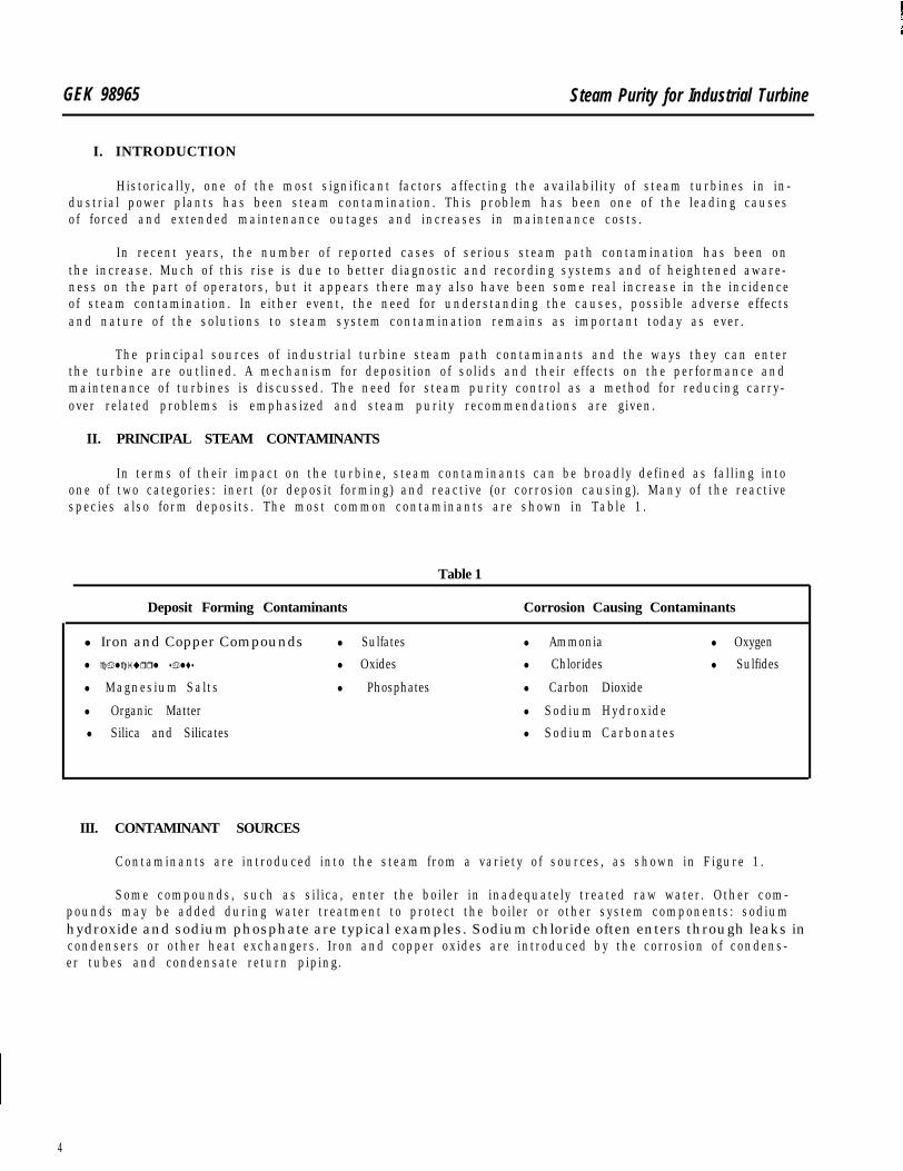
II. PRINCIPAL STEAM CONTAMINANTS
In terms of their impact on the turbine, steam contaminants can be broadly defined as falling intoone of two categories: inert (or deposit forming) and reactive (or corrosion causing). Many of the reactivespecies also form deposits. The most common contaminants are shown in Table 1.
Table 1
Deposit Forming Contaminants Corrosion Causing Contaminants
l Iron and Copper Compounds l Sulfates l Ammonia l Oxygenl calciurrl salts l Oxides l Chlorides l Sulfides
l Magnesium Salts l Phosphates l Carbon Dioxide
l Organic Matter l Sodium Hydroxidel Silica and Silicates l Sodium Carbonates
III. CONTAMINANT SOURCES
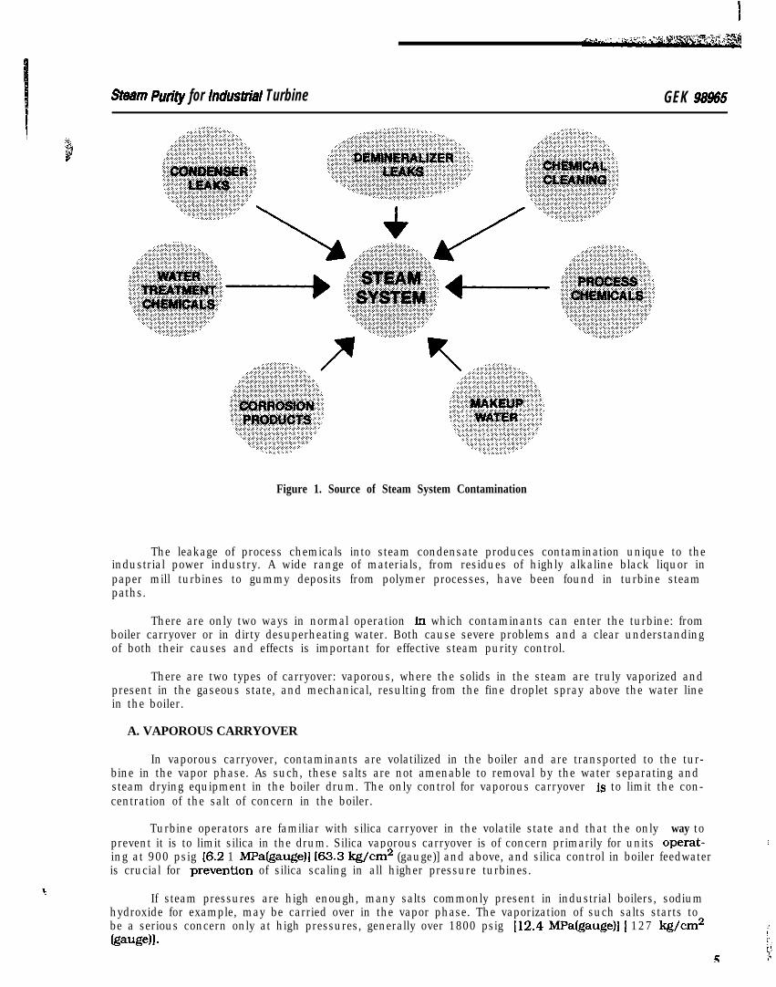
Contaminants are introduced into the steam from a variety of sources, as shown in Figure 1.
Some compounds, such as silica, enter the boiler in inadequately treated raw water. Other com-pounds may be added during water treatment to protect the boiler or other system components: sodiumhydroxide and sodium phosphate are typical examples. Sodium chloride often enters through leaks incondensers or other heat exchangers. Iron and copper oxides are introduced by the corrosion of condens-er tubes and condensate return piping.
4
Sham Putity for Induslrial Turbine GEK 96965
Figure 1. Source of Steam System Contamination
The leakage of process chemicals into steam condensate produces contamination unique to theindustrial power industry. A wide range of materials, from residues of highly alkaline black liquor inpaper mill turbines to gummy deposits from polymer processes, have been found in turbine steampaths.
There are only two ways in normal operation fn which contaminants can enter the turbine: fromboiler carryover or in dirty desuperheating water. Both cause severe problems and a clear understandingof both their causes and effects is important for effective steam purity control.
There are two types of carryover: vaporous, where the solids in the steam are truly vaporized andpresent in the gaseous state, and mechanical, resulting from the fine droplet spray above the water linein the boiler.
A. VAPOROUS CARRYOVER
In vaporous carryover, contaminants are volatilized in the boiler and are transported to the tur-bine in the vapor phase. As such, these salts are not amenable to removal by the water separating andsteam drying equipment in the boiler drum. The only control for vaporous carryover is to limit the con-centration of the salt of concern in the boiler.
Turbine operators are familiar with silica carryover in the volatile state and that the only way toprevent it is to limit silica in the drum. Silica vaporous carryover is of concern primarily for units operat-ing at 900 psig 16.2 1 MPa(gauge)] 163.3 kg/cm2 (gauge)] and above, and silica control in boiler feedwateris crucial for preventfon of silica scaling in all higher pressure turbines.
If steam pressures are high enough, many salts commonly present in industrial boilers, sodiumhydroxide for example, may be carried over in the vapor phase. The vaporization of such salts starts tobe a serious concern only at high pressures, generally over 1800 psig 112.4 MPa(gauge)I [ 127 kg/cm2@-gelI.
5
It
GEK 98965 Steam Purity for Industrial Turbine
The current trend to higher operating pressures may make vaporous carryover, now principallyIf concern only in high pressure utility units, a significant contributor to industrial turbine problems.
B. MECHANICAL CARRYOVER
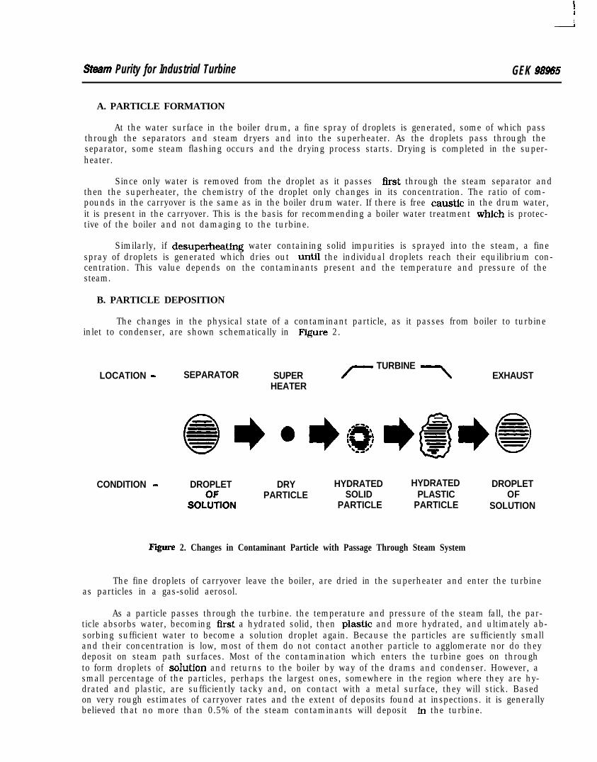
Mechanical carryover is the principal cause of industrial turbine contamination.
The working effectiveness of the steam separator is influenced by mechanical design, componentfabrication and installation, steam production rates, drum water level, load change rates and drum wa-ter chemistry. The major factors affecting mechanical carryover are shown in Table 2.
Table 2
MECHANICAL CARRYOVER
l Oversteaming
l High Water Levels
l High Drum Solids
l Separator Problems
l Rapid Load Changes
l Chemical Contamination
An improperly designed separator may itself be the problem, but more often mechanical carryoveris caused by overloading of the separator, by operating the boiler at greater than design output. This ispartfcularly true for older boilers where the conservative heat transfer designs give capacity marginswhich allow continuous operation considerably above rated load. Modem boiler designs do not allow op---ation which greatly exceeds rated loads. If the boiler contains adequate moisture separation and steam
ying capacity in the drum, carryover will be essentially constant over most of the load range. However,tpid load changes can cause surging and priming which the separator cannot handle. This has plaguedlme gas turbine exhaust and process heat recovery package boilers, particularly those which have the
capability for auxiliary f%-ing. These boilers may have steam separators which are adequate for the stea-dy-state full-load conditions, whether fired or unfired. but cannot handle the transients which occurwith very rapid load changes. Such units have shown very large excursions from acceptable steam purityin the first minutes of auxiliary firing.
C. DESUPERHEATING WATER
Attemperation with contaminated water causes severe fouling of both boilers and superheatersand is particularly damaging when boiler feedwater, containing free caustic alkalinity, or dirty conden-sate, containing process chemicals, are used.
Depending on the design of the boiler, both the superheater and the turbine, or the turbine alonemaybe affected. Ifdesuperheating water is dirty, and is sprayed at midspan, both turbine and superheat-er will be contaminated. Attemperation after the steam has passed through the superheater affects onlythe turbine. Contamination by way of the attemperator can only be prevented by ensuring the supplyof clean desuperheating water.
When contamination of condensate occurs in a cogeneration plant, where one power generationfacility serves several industrial users, locating its source can be especially troublesome. All returningcondensate streams must be checked for contamination, including those from users who are on line onlyintermittently.
I V . CONTAMINANT DEPOSITION AND CHEMISTRY
The origins of the contaminants have been described and now we can consider how they are intro-uced to the steam, transported to the turbine and deposited on the surfaces of the buckets and nozzles
of the steam path.
6
St6sm Purity for Industrial Turbine GEK 98965
A. PARTICLE FORMATION
At the water surface in the boiler drum, a fine spray of droplets is generated, some of which passthrough the separators and steam dryers and into the superheater. As the droplets pass through theseparator, some steam flashing occurs and the drying process starts. Drying is completed in the super-heater.
Since only water is removed from the droplet as it passes first through the steam separator andthen the superheater, the chemistry of the droplet only changes in its concentration. The ratio of com-pounds in the carryover is the same as in the boiler drum water. If there is free caustic in the drum water,it is present in the carryover. This is the basis for recommending a boiler water treatment which is protec-tive of the boiler and not damaging to the turbine.
Similarly, if desuperheating water containing solid impurities is sprayed into the steam, a finespray of droplets is generated which dries out until the individual droplets reach their equilibrium con-centration. This value depends on the contaminants present and the temperature and pressure of thesteam.
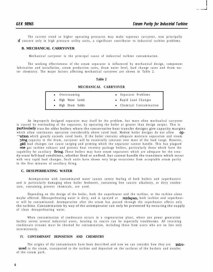
B. PARTICLE DEPOSITION
The changes in the physical state of a contaminant particle, as it passes from boiler to turbineinlet to condenser, are shown schematically in F’fgure 2.
TURBINELOCATION - SEPARATOR SUPER /- \ EXHAUST
HEATER
CONDITION - DROPLET
SOL%ON
DRYPARTICLE
HYDRATEDSOLID
PARTICLE
HYDRATEDPLASTIC
PARTICLE
DROPLETOF
SOLUTION
Figure 2. Changes in Contaminant Particle with Passage Through Steam System
The fine droplets of carryover leave the boiler, are dried in the superheater and enter the turbineas particles in a gas-solid aerosol.
As a particle passes through the turbine. the temperature and pressure of the steam fall, the par-ticle absorbs water, becoming first a hydrated solid, then plasttc and more hydrated, and ultimately ab-sorbing sufficient water to become a solution droplet again. Because the particles are sufficiently smalland their concentration is low, most of them do not contact another particle to agglomerate nor do theydeposit on steam path surfaces. Most of the contamination which enters the turbine goes on throughto form droplets of soluUon and returns to the boiler by way of the drams and condenser. However, asmall percentage of the particles, perhaps the largest ones, somewhere in the region where they are hy-drated and plastic, are sufficiently tacky and, on contact with a metal surface, they will stick. Basedon very rough estimates of carryover rates and the extent of deposits found at inspections. it is generallybelieved that no more than 0.5% of the steam contaminants will deposit in the turbine.
GEK 98965 Steam Purity for industrial Turbine
C. CHEMISTRY
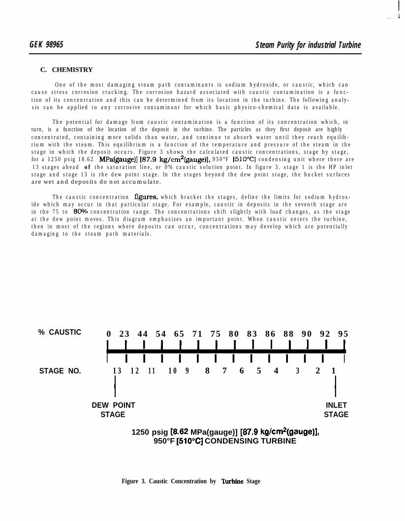
One of the most damaging steam path contaminants is sodium hydroxide, or caustic, which cancause stress corrosion cracking. The corrosion hazard associated with caustic contamination is a func-tion of its concentration and this can be determined from its location in the turbine. The following analy-sis can be applied to any corrosive contaminant for which basic physico-chemical data is available.
The potential for damage from caustic contamination is a function of its concentration which, inturn, is a function of the location of the deposit in the turbine. The particles as they first deposit are highlyconcentrated, containing more solids than water, and continue to absorb water until they reach equilib-rium with the steam. This equilibrium is a function of the temperature and pressure of the steam in thestage in which the deposit occurs. Figure 3 shows the calculated caustic concentrations, stage by stage,for a 1250 psig 18.62 MPafgauge)] [87.9 kg/cm2(gauge)l. 950°F [51O”C] condensing unit where there are13 stages ahead of the saturation line, or 0% caustic solution point. In figure 3. stage 1 is the HP inletstage and stage 13 is the dew point stage. In the stages beyond the dew point stage, the bucket surfacesare wet and deposits do not accumulate.
The caustic concentration figures, which bracket the stages, define the limits for sodium hydrox-ide which may occur in that particular stage. For example, caustic in deposits in the seventh stage arein the 75 to 80% concentration range. The concentrations shift slightly with load changes, as the stageat the dew point moves. This diagram emphasizes an important point. When caustic enters the turbine,then in most of the regions where deposits can occur, concentrations may develop which are potentiallydamaging to the steam path materials.
% CAUSTIC 0 23 44 54 65 71 75 80 83 86 88 90 92 95
I I I I I I I I I I I I I ISTAGE NO. 13 12 11 10 9 8 7 6 5 4 3 2 1
I IDEW POINT INLET
STAGE STAGE
1250 psig [8.62 MPa(gauge)] [87.9 kg/cm*(gauge)],950°F [510°C] CONDENSING TURBINE
Figure 3. Caustic Concentration by ‘Ihrbiie Stage
Steam Purify for lndusiri~l Turbine GEK 98965
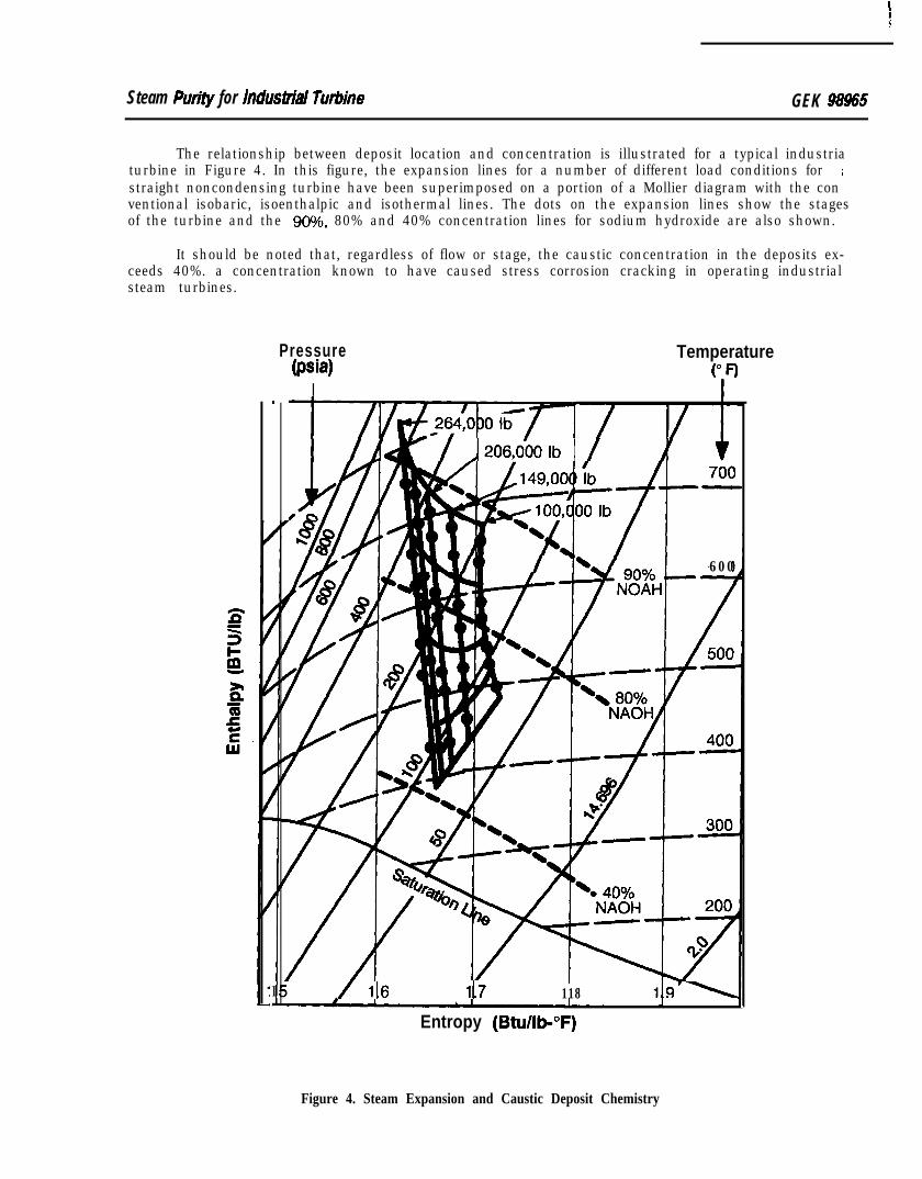
The relationship between deposit location and concentration is illustrated for a typical industriaturbine in Figure 4. In this figure, the expansion lines for a number of different load conditions for ;straight noncondensing turbine have been superimposed on a portion of a Mollier diagram with the conventional isobaric, isoenthalpic and isothermal lines. The dots on the expansion lines show the stagesof the turbine and the 90%. 80% and 40% concentration lines for sodium hydroxide are also shown.
It should be noted that, regardless of flow or stage, the caustic concentration in the deposits ex-ceeds 40%. a concentration known to have caused stress corrosion cracking in operating industrialsteam turbines.
Pressure(psia)
I
Temperature
‘ifl.
I.
/ A206,0bOIb 1 /
/ 600
/ 116 ll.7 118
Entropy (Btu/lb-°F)
Figure 4. Steam Expansion and Caustic Deposit Chemistry
GEK 98965 Steam Purity for Industrial Turbine
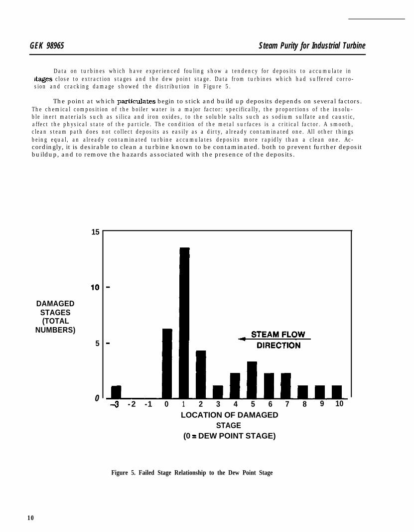
Data on turbines which have experienced fouling show a tendency for deposits to accumulate instages close to extraction stages and the dew point stage. Data from turbines which had suffered corro-sion and cracking damage showed the distribution in Figure 5.
The point at which particulates begin to stick and build up deposits depends on several factors.The chemical composition of the boiler water is a major factor: specifically, the proportions of the insolu-ble inert materials such as silica and iron oxides, to the soluble salts such as sodium sulfate and caustic,affect the physical state of the particle. The condition of the metal surfaces is a critical factor. A smooth,clean steam path does not collect deposits as easily as a dirty, already contaminated one. All other thingsbeing equal, an already contaminated turbine accumulates deposits more rapidly than a clean one. Ac-cordingly, it is desirable to clean a turbine known to be contaminated. both to prevent further depositbuildup, and to remove the hazards associated with the presence of the deposits.
15
DAMAGEDSTAGES(TOTAL
NUMBERS)
5
04 -2 -1 0 1 2 3 4 5 6 7 8 9 10
LOCATION OF DAMAGEDSTAGE
(0 = DEW POINT STAGE)
Figure 5. Failed Stage Relationship to the Dew Point Stage
10
Ii
&am Purity for Induslnal Turbine GEK 98965
V. EFFECTS OF CONTAMINANTS
In the past, the effects that steam path deposits can have on the turbine have frequently focusedon just one aspect of the overall problem - - the phenomenon of stress corrosion cracking. The emphasison this very important factor should not be permitted to obscure the very real importance of the othereffects of contamination as far as overall steam turbine performance is concerned. These include degra-dation of thermal efficiency, deterioration of mechanical performance and various kinds of metallurgicaldamage. In severe cases, the final result can be a forced outage, a prolonged maintenance outage or anunwelcome increase in maintenance costs.
A. EFFICIENCY DETERIORATION
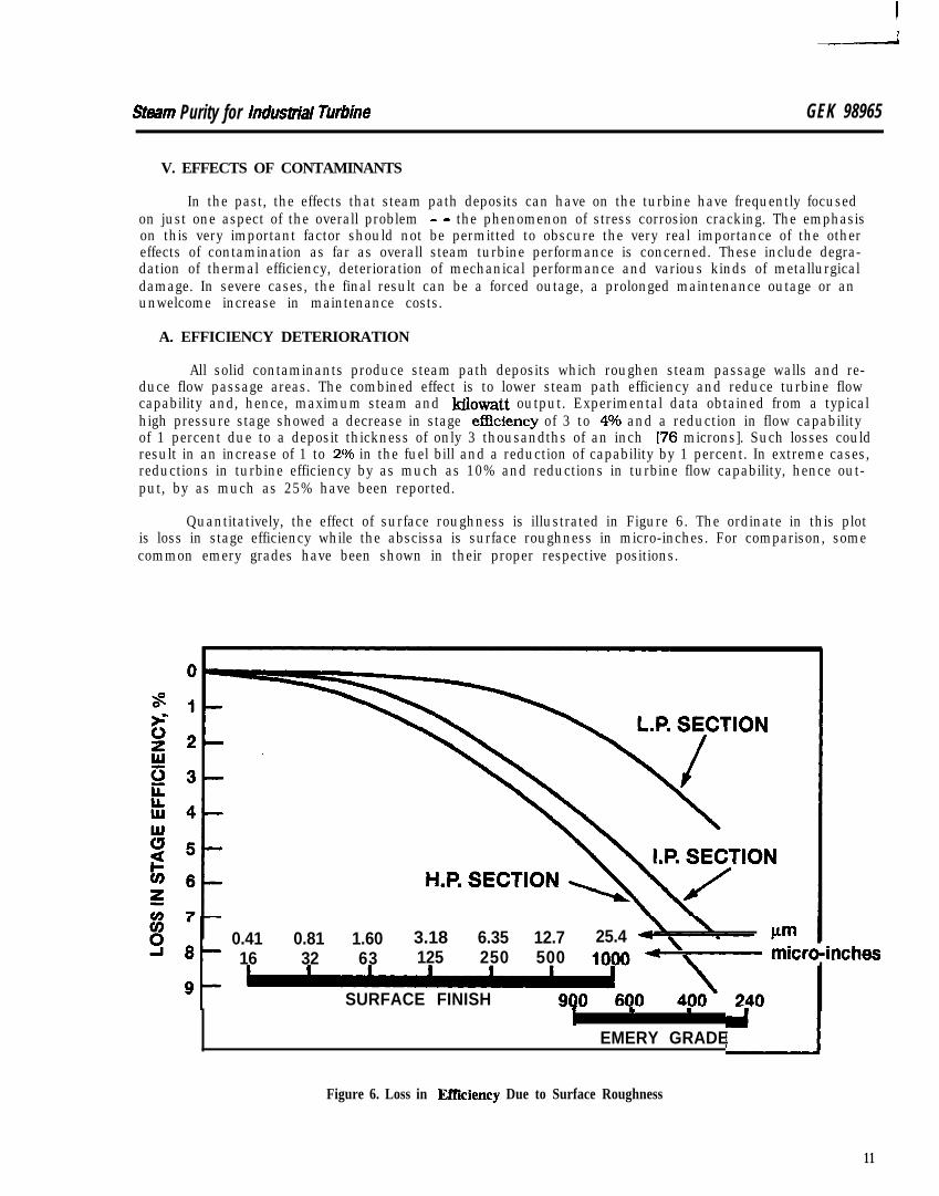
All solid contaminants produce steam path deposits which roughen steam passage walls and re-duce flow passage areas. The combined effect is to lower steam path efficiency and reduce turbine flowcapability and, hence, maximum steam and ldlowatt output. Experimental data obtained from a typicalhigh pressure stage showed a decrease in stage effkiency of 3 to 4O/6 and a reduction in flow capabilityof 1 percent due to a deposit thickness of only 3 thousandths of an inch 176 microns]. Such losses couldresult in an increase of 1 to 2O/6 in the fuel bill and a reduction of capability by 1 percent. In extreme cases,reductions in turbine efficiency by as much as 10% and reductions in turbine flow capability, hence out-put, by as much as 25% have been reported.
Quantitatively, the effect of surface roughness is illustrated in Figure 6. The ordinate in this plotis loss in stage efficiency while the abscissa is surface roughness in micro-inches. For comparison, somecommon emery grades have been shown in their proper respective positions.
0.41 0.81 1.60 3.18 6.35 12.7 25.416 32 63 125 250 500
SURFACE FINISH _I . .
EMERY GRADE
Figure 6. Loss in Effiiency Due to Surface Roughness
11
GEK 98965 Steam Purity for Industrial Turbine
A new and clean bucket has a surface finish between 16 and 32 micro-inches [0.41 - 0.8 1 mm]and the surfaces in dirty stages are comparable to a 100 grit paper or rougher. Even though only a tenthto a quarter of the stages before the dew point may be affected, the decline in efficiency in those stagesmay be severe.
Losses are greatest in high pressure stages where the ratio of passage wall surface to flow areais high and lowest in low pressure stages where flow areas are relatively large.
B. DEGRADED MECHANICAL PERFORMANCE
The mechanical performance of steam turbine components can be adversely affected by both inertand reactive chemical contaminants in the steam. The common effects include:
l Thrust bearing overloading and, in severe cases, thrust b-ring damage
l Degraded speed control
l Loss of over-speed protection
l Erratic pressure control
l Excessive shaft packing wear
Deposit accumulation in clearance spaces of control valve stem glands can effectively immobilizeflow control valves in primary and extraction control stages. This can result in loss of speed and pressurecontrol and, occasionally, of overspeed protection.
C. CORROSION DAMAGE
Loss of efhciency and degradation of mechanical performance are the more common results ofcontamination. However, in relatively rare but potentially very serious cases, significant metallurgicaldamage can result from carryover when corrosive salts are involved. Some of these instances include:
l Pitting corrosion of stainless steel bucket materials:
l Pitting and general corrosion of rotor materials, and
l Stress corrosion cracking.
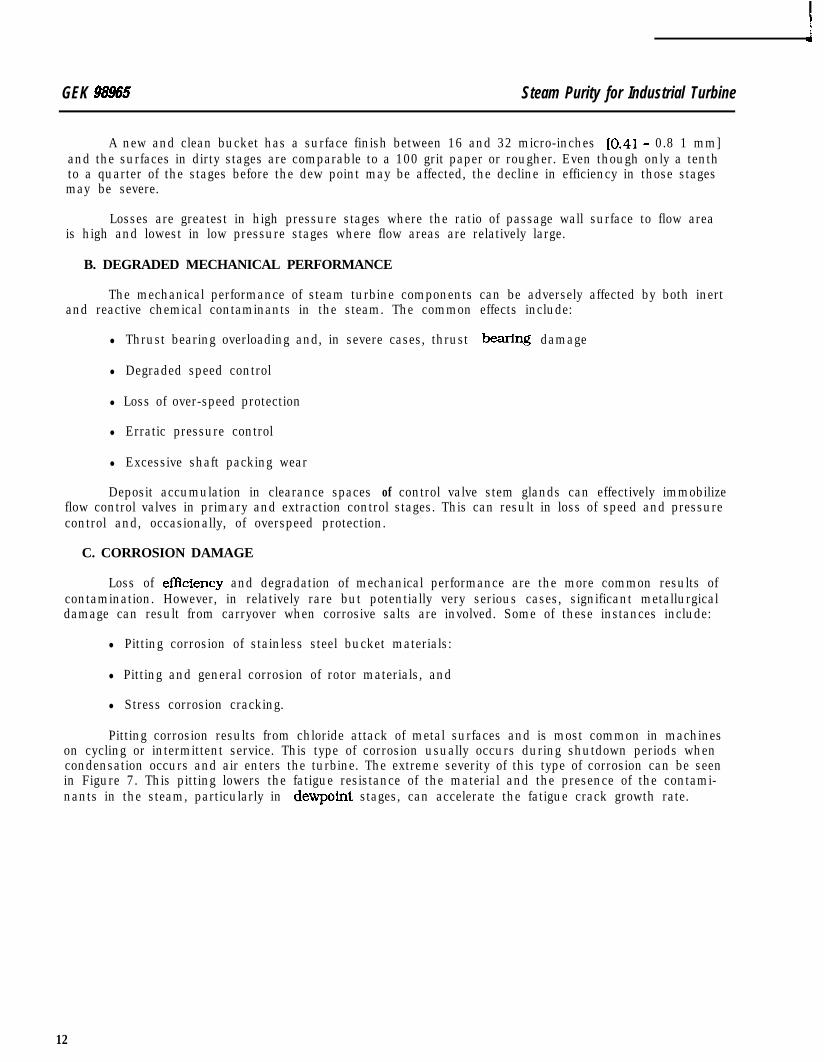
Pitting corrosion results from chloride attack of metal surfaces and is most common in machineson cycling or intermittent service. This type of corrosion usually occurs during shutdown periods whencondensation occurs and air enters the turbine. The extreme severity of this type of corrosion can be seenin Figure 7. This pitting lowers the fatigue resistance of the material and the presence of the contami-nants in the steam, particularly in dewpoint stages, can accelerate the fatigue crack growth rate.
12
Steam Purity for Industrial Turbine GEK 9&N
Figure 7. Bucket Pitting
The damage to the row of buckets shown in Figure 7 is permanent and the performance can onlybe restored by replacement of the row.
r
13

GEK 98965 Steam Purity for Industrial Turbine
The severe pitting and corrosion of bucket surfaces can be seen in closer detail in Figure 8.
Severe, linked pitting can result in fatigue fractures of the type seen in Figure 9.
Figure 8. Bucket Pitting - Closeup
Figure 9. Fatigue Fracture
14
S&am Purfty for Indusirial Turbine GEK 98965
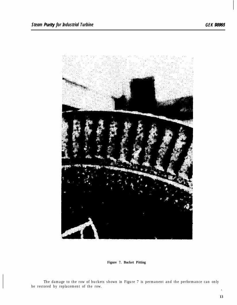
Figure 1Oa. View in Radial Plane Showing Advanced Stage of StressCorrosion Cracking in Wheel Hooks (3x Size)
Fiiure lob. View Showing Branched, Intergranular Pattern (-100x Size)
Of all the serious consequences of turbine steam path contamination, the one receiving most at-tention in recent years has been stress corrosion cracking. In industrial turbines, stress corrosion-re-lated failures have been rare and have most commonly been related to serious and prolonged contamina-tion of the steam path by caustic-containing contaminants.
Figure 10a shows the cross section of a turbine wheel which suffered a stress corrosion failure.The cracks emanating from the fillets can be clearly seen in the Eigure lob closeup. These have thebranched and intergranular pattern which is characteristic of stress corrosion cracking. These wheelhooks are highly loaded. When the cracks grow long enough that the remaining metal can no longer sus-tam the load, failure occurs.
15
GEK 98955 Steam Purity for Industrial Turbine
D. SHUTDOWN CORROSION
Units which operate with somewhat contaminated steam and without obvious corrosion prob-lems may suffer serious damage during shutdown periods if no protective measures are taken.
The presence of sodium chloride in deposits can cause severe pitting of 12 Cr buckets if humidair is allowed to enter the turbine during a shutdown. The simultaneous presence of oxygen, water andchloride ion on the surface of 12 Cr steel is necessary for pitting. The exclusion of one of them can preventthe corrosion.
There have been incidents of serious corrosion in industrial turbines where process chemicalshave entered through exhaust sections of noncondensing units and through extraction lines and dramsof condensing turbines during shutdown periods.
A recent approach to the prevention of both types of shutdown-related corrosion is the use of dryair. A dehumidification unit is connected to the turbine and produces a stream of warmed (150-180°F[65.6-82.2”CI and dried air which is passed through the turbine to prevent water condensation and entryof corrosive materials.
VI. MATERIAL SELECTION
The question is often raised, can materials be substituted that will make the turbine safe fromcaustic attack? The answer is no. There are no practical material choices which are inert to the corro-dants which have been discussed and which possess the mechanical properties necessary for perform-ance in steam path components. Materials used for critical steam turbine components are selected fortheir combination of high and low temperature strength, their toughness, machinability, formability and
:neral resistance to corrosion attack in steam environments of acceptable quality.
Laboratory tests of various materials used in the steam path have shown that none are totallynnmune to stress corrosion cracking. Tests have also shown that, if the chemical environment is suffi-ciently aggressive, stress corrosion cracking can occur at stress levels below those required for a reason-able turbine design.
In order to operate safely in the thermodynamic regions suggested by economics and good engi-neering practice, the purity of the steam must be carefully controlled. As it is impractical to operate attemperatures and pressures which minimize the risks of contamination, the only alternative is to mini-mize the contamination of the turbine steam path.
VII. CARRYOVER PREVENTION
Under normal operating conditions, the total elimination of carryover is not possible and onemust be concerned with practical and economical ways of controlling and monitoring its level such thatit does not create damage to the turbine.
The three main factors in a systematic approach to carryover control are (1) design and implemen-tation of water and steam chemistry controls which protect both boiler and turbine, (2) prudent operationof the boiler and attemperator and (3) the use of steam purity monitoring.
A. SYSTEM MANAGEMENT
The only practical approach to the elimination of steam path contamination problems is to ensurethat only acceptably pure steam enters the turbine. This involves management of all facets of the steam-water chemistry, and suitable control and maintenance of steam generators and other mechanical com-ponents.
Steam generation equipment must have adequate moisture separation and steam drying capacityand the boilers be operated according to the industry or other manufacturers’ recommendations for max-imizing steam purity.
16
Steam Purily for Industrial Turbine GEK 98965
A water treatment specialist should set up a comprehensive water conditioning program with pro-vision for control of all parts of the system: raw water, boiler feedwater, drum conditions, and the com-plete condensate system. Only when water conditioning is an integral part of the overall plant operatingsystem can long-term, trouble-free operation be achieved. Makeup water treatment must be tailored toaccommodate the operating demands of the boiler and the source of raw water. Most industrial steamsystems now require dernineralization of raw water for makeup. Ion exchange systems must be moni-tored to preclude breakthrough ofcontammants. Duringregeneration, care must be taken that contami-nation of product water streams or stored water is avoided.
Conductivity monitors should be present on all makeup and condensate streams and changesin conductivity investigated promptly for cause.
The secondary water treatment for control of drum conditions is primarily tailored for boiler pro-tection but should be specified with the turbine in mind. Oftentimes, treatment involving high levels offree caustic alkalinity is used to guard against boiler damage, in the event of a serious condenser failure,without regard for the potential effects of the boiler water when it is carried over to the turbine.
B. STEAM PURITY
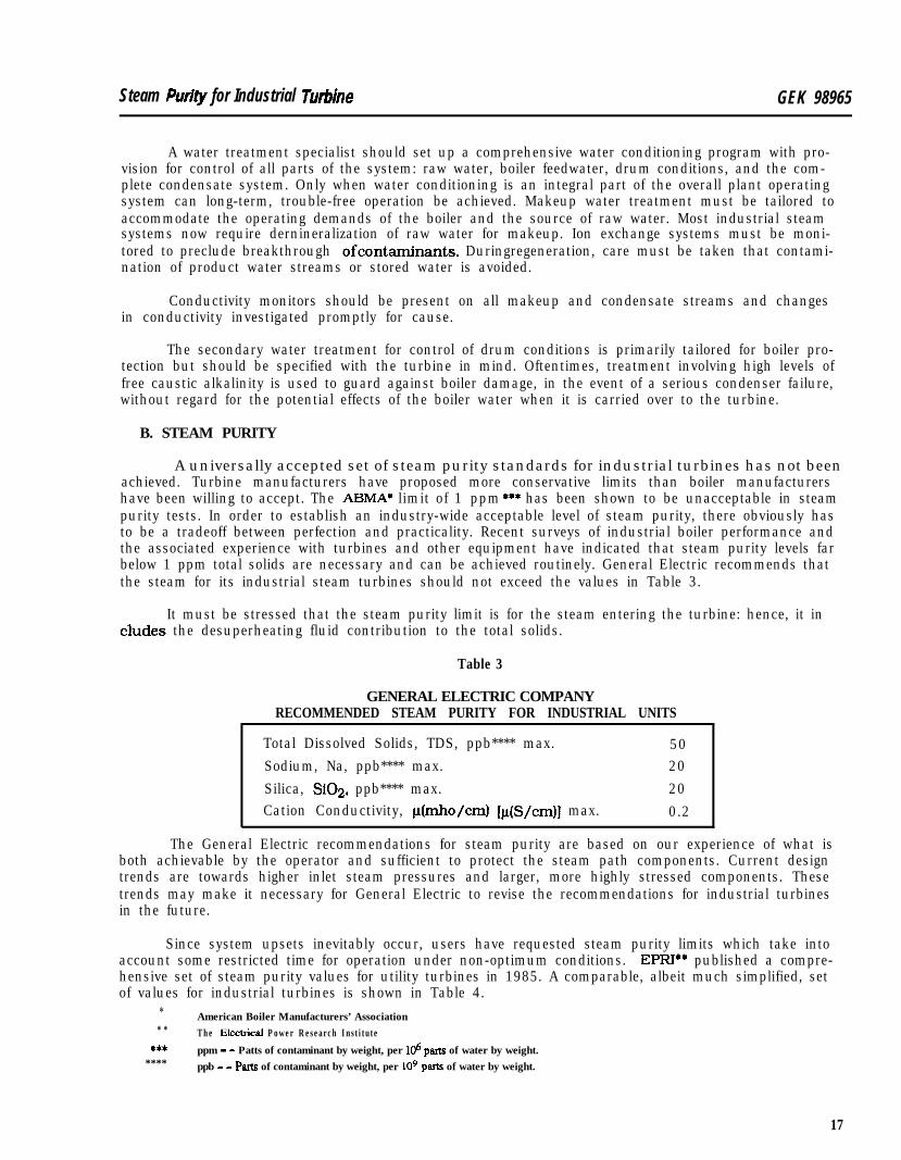
A universally accepted set of steam purity standards for industrial turbines has not beenachieved. Turbine manufacturers have proposed more conservative limits than boiler manufacturershave been willing to accept. The ABMA* limit of 1 ppm *** has been shown to be unacceptable in steampurity tests. In order to establish an industry-wide acceptable level of steam purity, there obviously hasto be a tradeoff between perfection and practicality. Recent surveys of industrial boiler performance andthe associated experience with turbines and other equipment have indicated that steam purity levels farbelow 1 ppm total solids are necessary and can be achieved routinely. General Electric recommends thatthe steam for its industrial steam turbines should not exceed the values in Table 3.
It must be stressed that the steam purity limit is for the steam entering the turbine: hence, it ineludes the desuperheating fluid contribution to the total solids.
Table 3
GENERAL ELECTRIC COMPANYRECOMMENDED STEAM PURITY FOR INDUSTRIAL UNITS
Total Dissolved Solids, TDS, ppb**** max.Sodium, Na, ppb**** max.Silica, SiO2. ppb**** max.Cation Conductivity, lt(mho/cm) [@/cm)] max.
5020200.2
The General Electric recommendations for steam purity are based on our experience of what isboth achievable by the operator and sufficient to protect the steam path components. Current designtrends are towards higher inlet steam pressures and larger, more highly stressed components. Thesetrends may make it necessary for General Electric to revise the recommendations for industrial turbinesin the future.
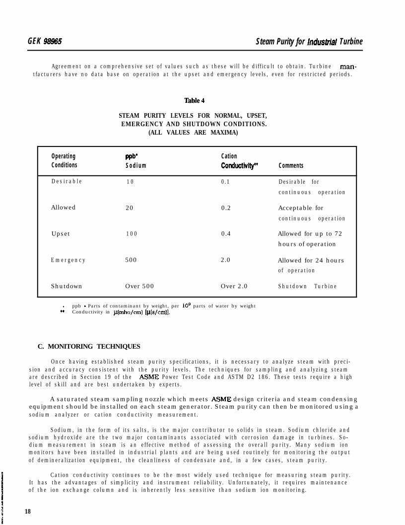
Since system upsets inevitably occur, users have requested steam purity limits which take intoaccount some restricted time for operation under non-optimum conditions. EPRI** published a compre-hensive set of steam purity values for utility turbines in 1985. A comparable, albeit much simplified, setof values for industrial turbines is shown in Table 4.
** *
t******
American Boiler Manufacturers’ AssociationT h e EiIectricaI P o w e r R e s e a r c h I n s t i t u t e
ppm - - Patts of contaminant by weight, per 106 parts of water by weight.ppb - - Parts of contaminant by weight, per lo9 parts of water by weight.
17
GEK 98965 Steam Purity for lndusbrial Turbine
Agreement on a comprehensive set of values such as these will be difficult to obtain. Turbine man-tfacturers have no data base on operation at the upset and emergency levels, even for restricted periods.
STEAM PURITY LEVELS FOR NORMAL, UPSET,EMERGENCY AND SHUTDOWN CONDITIONS.
(ALL VALUES ARE MAXIMA)
Operat ingCondit ions
D e s i r a b l e
wb*S o d i u m
1 0
Cat ionConductivity~
0.1
Comments
Desirable for
continuous operation
Allowed 20 0.2 Acceptable for
continuous operation
Upset 1 0 0 0.4 Allowed for up to 72
hours of operation
E m e r g e n c y 500 2.0 Allowed for 24 hoursof operation
Shutdown Over 500 Over 2.0 Shutdown Turbine
l ppb - Parts of contaminant by weight, per 10’ parts of water by weight** Conductivity in p(mho/cm) [p(s/cm)].
C. MONITORING TECHNIQUES
Once having established steam purity specifications, it is necessary to analyze steam with preci-sion and accuracy consistent with the purity levels. The techniques for sampling and analyzing steamare described in Section 19 of the ASME Power Test Code and ASTM D2 186. These tests require a highlevel of skill and are best undertaken by experts.
A saturated steam sampling nozzle which meets ASME design criteria and steam condensingequipment should be installed on each steam generator. Steam purity can then be monitored using asodium analyzer or cation conductivity measurement.
Sodium, in the form of its salts, is the major contributor to solids in steam. Sodium chloride andsodium hydroxide are the two major contaminants associated with corrosion damage in turbines. So-dium measurement in steam is an effective method of assessing the overall purity. Many sodium ionmonitors have been installed in industrial plants and are being used routinely for monitoring the outputof demineralization equipment, the cleanliness of condensate and, in a few cases, steam purity.
Cation conductivity continues to be the most widely used technique for measuring steam purity.It has the advantages of simplicity and instrument reliability. Unfortunately, it requires maintenanceof the ion exchange column and is inherently less sensitive than sodium ion monitoring.
18
Steam Purity for Industrial Turbine GEK !XW5
Ion chromatography is a very useful tool for characterizing the impurities in steam and relatingthem to fluctuations in cation conductivity. It is not an on-line method so continuous monitoring is notpossible with this technique. However, very good correlations have been obtained between cation con-ductivity values and quantitative ion chromatography of retained condensate samples.
D. OPERATOR PARTICIPATION
One of the key factors involved in achieving effective control of steam purity is an understandingon the part of turbine operators of the importance of continuously maintaining the specified steam puritylevels. This understanding includes an appreciation of the possible consequences of chemical contami-nation of the turbine steam path and the importance of recording every instance of steam contaminationso that proper remedial action can be taken.
Operator training programs should provide an understanding of the nature, sources and possibleeffects of the chemical contaminants most likely to be encountered in their steam system. Particular em-phasis should be placed on the importance of round the clock, 24 hours a day, 7 days a week attentionto this subject.
F’inally, in the event that carryover occurs, it is important that operators know what happened,when it happened, the severity of the incident, and the probable duration. This kind of factual informa-tion is of immense help when the potential long term effects of a steam path contamination incident mustbe balanced against the short term economic impacts of the various corrective actions available.
Equally important to the proper control of steam purity is the commitment of plant managementto the task of providing the water treatment facilities and the measurement and monitoring instrumenta-tion which are vital to the overall control plan. Without the instruments necessary to measure systemsteam purity performance, even the most knowledgeable and most highly motivated operators are help-less when system upsets and abnormalities occur.
VIII. SUMMARY
The goal is long term, reliable and economic operation of industrial steam turbines. One importantcontributor to this goal is to prevent the admission of harmful amounts of chemical contaminants intothe steam turbine. The technology to accomplish this is available but is not as widely applied as is desir-able.
Good control begins in the plant planning stage, with the proper selection of boilers, water treat-ment equipment and process and plant monitoring equipment. Steam purity control must be furtherpursued through the operational phase with the selection of competent water chemistry staff and thetraining of plant operating personnel at various levels.
Maintaining steam purity must be identified as a priority by top management. Managementshould emphasize this priority by providing the tools necessary to achieve this objective.
19
G E K 89593ARevis ion A , August 1984Reformatad, Mwch 1991
GE lndus trial & Power Sys ten;Steam Turbine
lhrbine Off-Frequency Operation
(50 Hz Units)
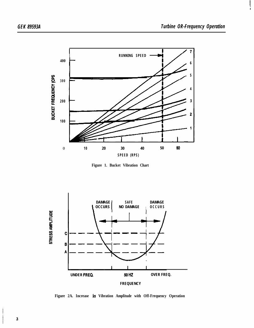
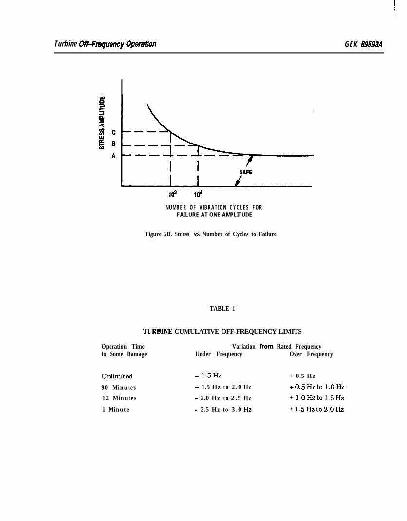
A steam turbine is comprised of many stages of turbine buckets of various lengths and designs,each of which has its own characteristic natural frequencies. This is illustrated in Figure 1, where thethree nearly horizontal lines represent resonant frequencies characteristic of one such bucket. The diag-onal lines drawn at integral multiples of the running speed, i.e., multiples of onceper-revolution repre-sent the stfmulus frequencies inherent in the steam flow. Turbines are carefully designed so that thebucket resonance and stimulus frequencies at rated speed are sufficiently far apart to avoid vibrationand excess stress. However, departures from rated speed will bring the stimulus frequencies closer tone or more of the bucket natural frequencies with resulting higher vibratory stresses. The diagramsin Figure 2 illustrate the phenomena involved in off-frequency operation. Figure 2A shows the buckevibration stress amplitude for a composite of the stages of the turbine as a function of running frequencyNote that as the turbine moves off frequency the stress amplitude increases and some damage is accu-mulated. Stress levels A, B and C in Figure 214 are also marked in Figure 2B. which shows a typical fatiguestrength curve for bucket structures. Note that below level A, the vibration stress amplitude is lowenough that the buckets can run indefinitely without any damage. Operation at stress level B would pro-duce a failure in 10,000 cycles of vibration and at a still higher stress level C. failure would occur at 1,000cycles.
An examination of vibration frequency data for different turbine stages leads to the acceptabletime limits for off-frequency operation given in Table 1.
Table 1 contains cumulative off-frequency time limits, that is, permissible operating times overthe life of the unit. As such, Table 1 represents the estimated minimum time to cracking of some partof the bucket structure, most likely to the tie wires or bucket covers. While tie wire and bucket covercracks are not in themselves catastrophic failures, they change the vibration behavior of the bucketsso that it is likely to have natural frequencies closer to running speed. This may produce bucket failureunder normal running conditions.
These instructions do not purport to cover all delalls or vatWions in equbment nor to provide for every possiblecontihgency to be met in connectton with krsWatlon, operetian or maintenance. Should further information be &shsd orshouldpattlcukproblems at&? which am not covered sufflckntty for the purchaser’s putposes the matter shouki benfemd to ths GE Company. COPYRIGHT 1991, GENERAL ELECTRIC COMPANY
GEK 89593A Turbine OR-Frequency Operation
400
300
2 0 0
1 0 0
I IRUNNING SPEED
r
6
5
c
4
3
O 1 0 20 30 40 50 60
S P E E D ( R P S )
Figure 1. Bucket Vibration Chart
DAMAGE SAFE
I
DAMAGE\ OCCURS NO DAMAGE O C C U R S
t ’I--- ----1 1-f
UNDER FREQ. 5oHZ OVER FREQ.
FREQUENCY
Figure 2A. Increase in Vibration Amplitude with Off-Frequency Operation
i
Turbine OSFmquency Operation GEK 99593A
NUMBER OF V IBRATION CYCLES FORFAILURE AT ONE AMPLITUDE
Figure 2B. Stress vs Number of Cycles to Failure
TABLE 1
WRBINE CUMULATIVE OFF-FREQUENCY LIMITS
Operation Timeto Some Damage
Variation from Rated FrequencyUnder Frequency Over Frequency
unlimited - 1.5Hz + 0.5 Hz
90 Minutes - 1.5 Hz to 2.0 Hz +0.5Hzto l.OHz
12 Minutes - 2.0 Hz to 2.5 Hz + l.OHzto 1.5Hz
1 Minute - 2.5 Hz to 3.0 Hz + 1.5Hzto2.0Hz
GEI 56556New Information, August 1956
ReformatW, January 1991
GE Power SystemsSteam Turbine
Atmosphere Relief Diaphragm
The atmosphere relief diaphragm is a safety feature which protects the exhaust hood and condens-er against excessive steam pressure in case the condenser water, for any reason, is lost.
I. DESIGN
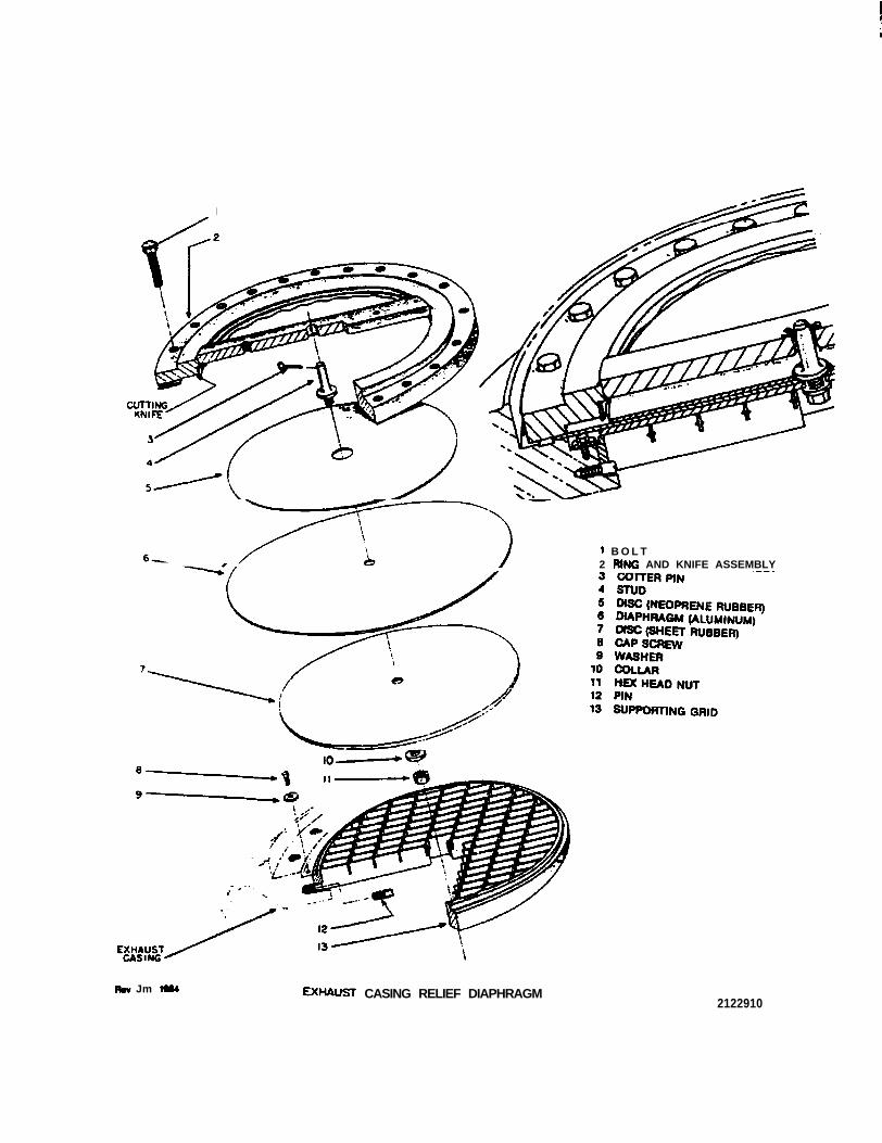
The relief diaphragm is mounted on the upper half of the exhaust casing. The supporting grid (13)fits into a recess in the exhaust casing and is held in position by washers (9). An arrangement of discs(5 and 7) and diaphragm (6) are held in position on the grid by the ring and knife assembly (2) which ibolted to the exhaust casing. Welded to the open face of the ring, is a bar which acts as a guide for thdisc and diaphragm assembly stud (4).
II. OPERATION
In normal operation of the turbine with proper conditions, the diaphragm is dished inward againstthe supporting grid (13) by atmospheric pressure. If for any reason the vacuum conditions should failallowing the internal exhaust hood pressure to increase, at approximately 5 pounds gage [34.5 kPa(gauge)) [352 g/cm2 (gauge)] the diaphragm is forced outward against the cutting knife on the assembly(2). cutting a disc free from the diaphragm. This relieves the exhaust pressure to atmosphere.
III. MAINTENANCE
A spare diaphragm is usually furnished with this device, and should it be replaced, it is of the ut-most importance that it be replaced with the same material of the same gauge thickness.
Tkse instructions do not purport to coverall &tails or varWions in equ@nent nor to pruvk& for evstypossiblecont&gency to bs met in connection with hW&tion, open?don or makrdsnance. Should further information be &sitsd orshould part/c&r problems ark which am not covensd sMicient/y for the putchaser’s purposes the matter should betsbmed t o the GE Company. @) ,Q.: r,CYCDA I Cl IffiTDl- -Ama-- brnw
I
1 B O L T2 RING AND KNIFE ASSEMBLY
lo-
Rev Jm lSM ~lUW!jT CASING RELIEF DIAPHRAGM2122910

GE/ 99368FRevision fi March 1999
Reformatted, September 19PJ
GE Power SystemsSteam Turbine
Recommended Practices for Protective Relaying,Electric Motors, and Electric Control Circuits
These instntotlons do not purport to wver e/l &Ws of varletions in equ@ment nor to pruvlde for ewyposs/b/ewntb!gsncy t o k met In wnnection with b&alMion, opsmtion ormahtenlanoe. Should futther information be desired orshould partMsrpnWems a&e which am not covered suffic&ntly for the putiaser’s purposes the m&W should bsrut&red to the GE Campy. fi ,QIQ eeuesr 1 em emTml* -A.#-- l I-
GE/ 90368 Recommended Practices
TABLE OF CONTENTS
I. GENERAL . . . . . . . . . . . . . . . . . . . . . . . . . . . . . . . . . . . . . . . . . . . . . . . . . . . . . . . . . . . . . . . . . . . . . . . . . . . . . . ...3
II. PROTECTIVE RELAYING . . . . . . . . . . . . . . . . . . . . . . . . . . . . . . . . . . . . . . . . . . . . . . . . . . . . . . . . . . . . . . . ...3
III. PREFERRED PRACTICES FOR PROTECTING THE TURBINE-GENERATOR . . . . . . . . . . . . . . . . . . . . 3A. Type A - Simultaneous Tripping Of Turbine Emergency Valves
And Generator Circuit Breakers . . . . . . . . . . . . . . . . . . . . . . . . . . . . . . . . . . . . . . . . . . . . . . . . . . . . . . . . 4B. TypeB-BackupRelays . . . . . . . . . . . . . . . . . . . . . . . . . . . . . . . . . . . . . . . . . . . . . . . . . . . . . . . . . . . . ...4C. Type C - Sequential Tripping Of The Turbine Emergency
Valves And Then The Generator Circuit Breaker(s) . . . . . . . . . . . . . . . . . . . . . . . . . . . . . . . . . . . . . . 4D. Type D-Tripping Generator And Field Breaker Without
Tripping The Turbine Emergency Valves . . . . . . . . . . . . . . . . . . . . . . . . . . . . . . . . . . . . . . . . . . . . . . . . 6
IV. ELECTRICMOTORS . . . . . . . . . . . . . . . . . . . . . . . . . . . . . . . . . . . . . . . . . . . . . . . . . . . . . . . . . . . . . . . . . . . . ...6
V . ELECTRICAL CONTROL CIRCUITS AND DEVICES . . . . . . . . . . . . . . . . . . . . . . . . . . . . . . . . . . . . . . . . . . 8
LIST OF FIGURES
Figure 1. TypicalIndustrialUnit . . . . . . . . . . . . . . . . . . . . . . . . . . . . . . . . . . . . . . . . . . . . . . . . . . . . . . . . . . . . . . . . . .-’ m-e 2. Typical Utility Unit . . . . . . . . . . . . . . . . . . . . . . . . . . . . . . . . . . . . . . . . . . . . . . . . . . . . . . . . . . . . . . . . . . . . .4
m-e 3. Typical Arrangement for Generator Tripping . . . . . . . . . . . . . . . . . . . . . . . . . . . . . . . . . . . . . . . . . . . . 5
Recommended Practices GE/ 9U368F
I. GENERAL
Turbine+generators are equipped with control systems and auxiliary components for normal online operation as well as for protection during unusual turbine generator operation or unusual circum-stances in the power plant which could result in damage to the turbine-generator. The emergency controlsystems back up normal on-line operating turbine control systems to provide the reliability and safe oper-ation required for turbine-generators. These control systems and components have been refined as a re-sult of years of experience in various environments and applications. They are subject however, to wear,aging, boiler carry-over deposits, oxide build-up on valve stems and bushings, and hydraulic system ox&dation and contamination. Proper maintenance of the turbine-generator is therefore very important inorder to keep the turbine and its auxiliary systems in proper operating condition.
The turbine has two independent speed control systems. The operating speed control is designedfor normal control of the turbine-generator and is capable of limiting turbine overspeed below emergencytrip speed following a sudden rated load rejection by the generator. The emergency trip system is designedto limit turbine over-speed to a safe level if the first level of speed control malfunctions. The emergencytrip system also serves as a means to rapidly remove load from the turbine when such action is necessary.
It is preferable from a turbine standpoint to first trip the inlet emergency valve(s) closed and thenopen the generator circuit breaker. This sequence minimizes the possibility of overspeeding the turbine,and is preferred over simultaneous closing of the stop valve and opening the generator breaker, or openingonly the generator breaker and permitting the turbine speed to rise under control of the speed controlsystem.
A steam turbinegenerator is, however, not a complete, self-sufllcient unit. It is combined witother equipment such as a boiler, condenser, auxiliaries, switchgear, piping, and related power plarequipment in order to be capable of generating electric power or supplying process steam. Certain practies and operating procedures have evolved as providing reliable and safe operation of the turbine-generator. The recommendations contained in this publication are based on this experience.
II. PROTECTIVE RELAYING
These recommendations clarify the position concerning protective relaying for turbine-genera-tors manufactured by GE Power Generation. Considering the turbine-generator as a separate unit, theserecommended protective relaying practices direct maximum attention to overspeed of the turbine-gener-ator following rejection of load due to mechanical or electrical fault. A customer may have system require-ments or power plant operating procedures and practices which necessitate taking exception to part, orall, of these recommendations. When this is the case, the customer or his appointed consultant shouldbe aware of the potential hazards introduced by each exception so that he can conduct a proper evalua-tion of the entire system, including the turbine-generator.
III. PREFERRED PRACTICE FOR PROTECTING THE TURBINE-GENERATOR
These recommendations do not disregard system problems which the preferred arrangementsmay complicate: however, the consequences of an uncontrolled overspeed cannot be taken lightly. Thedecision to arrange the relay tripping devices in a manner other than the recommended practices in-cluded in this publication can be made only by the customer or his authorized representative responsiblefor the electrical system design. It is suggested that all factors be considered and analyzed with due contern given to the relative importance of various recommendations and risks as related to a particulaplant requirement. The customer and his representative should be aware of the vital need for propemaintenance of the entire control system to minimize the risk involved.
GE/ 90368F Recommended Practices
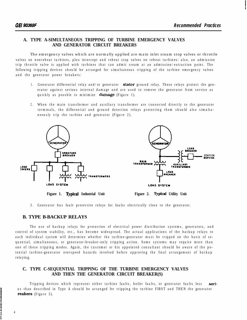
A. TYPE A-SIMULTANEOUS TRIPPING OF TURBINE EMERGENCY VALVESAND GENERATOR CIRCUIT BREAKERS
The emergency valves which are normally applied are main inlet steam stop valves or throttlevalves on nonreheat turbines, plus intercept and reheat stop valves on reheat turbines: also, an admissiontrip throttle valve is applied with turbines that can admit steam at an admission/extraction point. Thefollowing tripping devices should be arranged for simultaneous tripping of the turbine emergency valvesand the generator power breakers:
1 . Generator differential relay and/or generator stator ground relay. These relays protect the gen-erator against serious internal damage and are used to remove the generator from service asquickly as possble to minimize damage (Figure 1).
2 . When the main transformer and auxiliary transformer are connected directly to the generatorterminals, the differential and ground detection relays protecting them should also simulta-neously trip the turbine and generator (Figure 2).
Q3GENERATOR
LOlOSRLAaCR
b
STATIONSEavICE
YblNlRA*srOaYCR 4uYILIARv
LOAOEAUCNS
TRANSFORYER
Figure 1. ‘Qpical Industrial Unit Figure 2. ‘Qpical Utility Unit
3 . Generator bus fault protective relays for faults electrically close to the generator.
B. TYPE B-BACKUP RELAYS
The use of backup relays for protection of electrical power distribution systems, generators, andcontrol of system stability, etc., has become widespread. The actual applications of the backup relays toeach individual system will determine whether the turbine-generator must be tripped on the basis of se-quential, simultaneous, or generator-breaker-only tripping action. Some systems may require more thanone of these tripping modes. Again, the customer or his appointed consultant should be aware of the po-tential turbine-generator overspeed hazards involved before approving the final arrangement of backuprelaying.
C. TYPE C-SEQUENTIAL TRIPPING OF THE TURBINE EMERGENCY VALVESAND THEN THE GENERATOR CIRCUIT BREAKER(S)
Tripping devices which represent either turbine faults, boiler faults, or generator faults less seri-us than described in Type A should be arranged for tripping the turbine FIRST and THEN the generatorlreakers (Figure 3).
4
Recommended Practices GE1 90368F
SEQUENTIAL TRIP RELAY slYu~fANE0~s Tmp RELAY
\
GENERATOU
EMERGEUCY HYDAAULIC S Y S T E M CIRCUIT
TRIPS EMERGE NC Y V A L V E S BREAKEfiO R
ALLAY
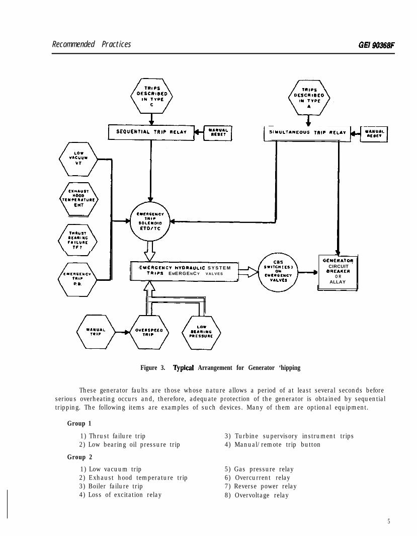
Figure 3. ‘Qpical Arrangement for Generator ‘hipping
These generator faults are those whose nature allows a period of at least several seconds beforeserious overheating occurs and, therefore, adequate protection of the generator is obtained by sequentialtripping. The following items are examples of such devices. Many of them are optional equipment.
Group 1
1) Thrust failure trip2) Low bearing oil pressure trip
3) Turbine supervisory instrument trips4) Manual/remote trip button
Group 2
1) Low vacuum trip2) Exhaust hood temperature trip3) Boiler failure trip4) Loss of excitation relay
5) Gas pressure relay6) Overcurrent relay7) Reverse power relay8) Overvoltage relay
5
GE/ W368F R e c o m m e n d e d Pfactices
The circuit breaker switches (CBS) are limit switches located on the turbine emergency valves and-e actuated when the valves close. Tripping the generator breakers by way of the CBS is the safest method) far as overspeed is concerned since it avoids the possibility of opening the generator breaker if the emer-
gency valves do not close. The tripping devices listed in Group 1 should actuate the solenoid trip instanta-neously.
For the tripping devices listed in Group 2, it may be desirable from a system standpoint, for thecustomer to Introduce a time delay between closing the stop valve(s) or throttle valve(s) and tripping thegenerator circuit breaker for some protective or trip devices. The time delay may be accomplished by anelectrical timing relay and should be no more than 90 seconds.
D. TYPE D-TRIPPING GENERATOR AND FIELD BREAKER WITHOUT TRIPPINGTHE TURBINE EMERGENCY VALVES
Certain electric power system protective relaying may, after weighing all factors, be arranged toinitiate immediate trip of the generator breaker without tripping the turbine. This minimizes the fault areahazard and the time required to put the turbinegenerator back on the line.
IX ELECTRIC MOTORS
The proper operation of the turbine-generator requires that electric motors furnished with the unitbe controlled with the utmost regard for their reliability and ability to function. Since motor starters andcontrol switches generally are not furnished with the turbine-generator, only the minimum requirements=-r these starters and switches are shown on the motor starter circuit diagrams. These diagrams represent
any years of successful experience.
The most important motors are those driving pumps for lubricating fluid and high-pressure hy-draulic fluid.
Examples of these pump motors are:
AC bear&j and seal oil pump motors
Auxiliary lubricating oil pump motors
Emergency bearing and seal oil pump motors
Generator sha. seal oil pump motors
Emergency lubricating oil pump motors
High-pressure hydraulic pump motors
Any interruption of the lubricating fluid supply to the turbine-generator system can cause exten-sive bearing and internal turbine part damage as well as prolonged and costly outage time. Loss of thehigh-pressure hydraulic system will result in closure of the emergency valves and shutting down the tur-bine. These motor starter circuits should accomplish the following functions. and the circuits recom-mended for these motors should not be compromised:
A. The motor control switches are to be spring-returned to the automatic start position. It shouldlot be possible to lock out the motors unless a deliberate procedure is followed. Examples of a deliberate
procedure would be: a switch with a pull-to-lockout stage for the OFF position: or a separate, inaccessibledeenergizing switch.
6
R8commended practices GElM368F
B. Signal lights should be provided which (1) indicate only when voltage is available and automatic start is possible, and (2) indicate when the motors are running. These lights are important for sever:reasons, such as indicating a switch left in the OFF position or lack of power to the starter circuit. A RUIlight may indicate a failure in another part of the lubricating system, the successful test of the automaticmotorstarting circuit, or may draw attention to a motor which has inadvertently been left running. A RUNlight does not necessarily mean that the pump is performing correctly.
C. The overload elements should be set only to alarm and not to trip motors driving lubricatingsystem and high-pressure hydraulic pumps. The cost of one of these motors is small compared to thepotential damage resulting from a lubrication system failure or forced outage of the turbine generator.An exception to this requirement may be possible on large auxiliary oil pump motors when they arebacked up by at least two other pumps.
D. For an emergency bearing (and seal) oil pump, any circuit breakers provided in the dc supplyto the motor which are equipped with relays for over-current protection must be set high enough to avoidtripout during the motor starting cycle. They should be set to at least 1.5 times the highest starting cur-rent measured under actual starting conditions, using fast-acting recording equipment, such as a brushrecorder. The peak current during starting will depend on the back e.m.f.. motor speed, supply voltage,etc., and may be as high as 5 times rated full-load current. If the circuit breakers are provided with thethermal overload contacts, they should be wired to alarm only. The use of fuses is not recommendedbecause, unlike circuit breakers, they cannot be tested for correct calibration.
E. On units which have a dc-motor-driven emergency oil pump, a special dc motor starter issupplied as standard. The starter provides extremely fast controlled starting of the dc motor to limit pres-sure dips in the lubrication system to a minimum of 5 psig when transferring from ac to dc motor pump
F. Some turbines have no shaft-driven oil pumps, and use combinations of ac motor pumps, dcmotor pumps and/or steam-driven pumps to supply lubricating oil for the turbine-generator. It is rec-ommended that the dc motor pump starter be energized either by the lube pressure switch or auxiliarycontacts on the ac motor pump starter(s) so that if the ac motor pump starter(s) opens, the dc motorpump starter will operate instantaneously and not wait for the lubricating system pressure switch tostart the dc motor pump.
G. Power for each ac-motor-driven lubricating system pump should be supplied from separateand independent sources. If independent power sources are not used, switching to an alternate powersource should be accomplished in less than one second. Reliability can be improved for systems withtwo ac motor pumps if switch arrangements and separate power sources are used so that either ac motorpump can be connected to either power source.
H. Sufficient dc battery capacity shall be provided so that the dc emergency bearing pump canoperate continuously for one-half hour for air-cooled generators and two hours for hydrogen-cooled gen-erators. One-half hour is the approximate time needed for the turbine rotor to come to rest after a tripout.and additional time is needed to purge hydrogen in the generator casing.
As a dram is imposed on the station batteries during dc motor operation, it is expected that thevoltage at the motor terminals will drop. This can be accepted within certain limits: however, insufficientbattery capacity will adversely affect motor pump performance.
The following limitations must be observed:
1 . The initial battery voltage should be 125 V dc + 5% or 250 V dc + 5%.
G E I 90368F Recommended Practices
2 . After starting the motor, terminal voltage should not drop below 90% of the nameplate voltageduring the first 30 minutes of emergency operation on station batteries.
3 . If the unit is hydrogen-cooled, the motor terminal voltage for the next 1.5 hours should notfall below 105 V dc (2 10 V dc on 240 V dc systems).
V. ELECTRICAL CONTROL CIRCUITS AND DEVICES
Electrical control circuits include protective circuits, testing circuits, remote and parallel opera-tion of components, automatic sequencing, and/or logic circuits and instrumentation. Certain of thesecircuits provide protection for the turbine-generator or its related equipment. Other circuits provide pro-tection to prevent physical damage to plant- or industry-related equipment, such as electrical switchgear,manufacturing processes, and boilers.
A . Emergency protective circuits are dc and use batteries to provide backup power if rectified sta-tion ac power is interrupted. Fusing these circuits reduces the reliability of the tripping circuitsin terms of available dc power. It is preferable from a turbine-generator standpoint not to fusethese tripping circuits, but other considerations may make it desirable to provide dc powersystem protection. Examples of these circuits are the electrical trip device (ETD) and the gener-ator circuit breaker trip system. AC power for tripping circuits is not recommended.
B . DC control circuits that are not turbinegenerator emergency protective circuits should haveprovisions for overcurrent protection using accepted industry standards. Examples of thesecircuits are:
1 . Test circuits where dc power is used in place of ac power.
2 . Transfer solenoid devices such as speed reset and transfer from pressure to speed control.
3. Annunciator circuits.
C. AC control circuits are not normally protective circuits in the sense of emergency circuits.These circuits should be protected by overcurrent devices using accepted industry standardsfor overcurrent settings.
GE Power Systems
General Electric CompanyOne River Road, Schenectao) NY 12345 .5180385.2211 T X : 1 4 5 3 5 4
GEK 32979AReformat&$ Mkwch 1 9 9 1
GE Industrial & Power System;Steam Turbine
Steam ‘lhrbine System Drains
These instructIons dc not purport to coyor all detalls or vartatjons In equ&ment nor to provide for everypossibieccnt&sncy to be met In connection with Astalbtlon, operation or maihtenanoe. Should further information be dsslmd orshouldpaHlcukwptvblems a&e which am not covend wfflcisntly for the putchaser’s purposes the matter should berefened to the GE Campy. COPYRIGHT 1991. GENERAL ELECTRIC CnMDAN”
GEK 32979A Steam Turbine System Drains
TABLE OF CONTENTS
I. INTRODUCTION . . . . . . . . . . . . . . . . . . . . . . . . . . . . . . . . . . . . . . . . . . . . . . . . . . . . . . . . . . . . . . . . . . . . . . . . . 3
I I . TYPES OF DRAINS . . . . . . . . . . . . . . . . . . . . . . . . . . . . . . . . . . . . . . . . . . . . . . . . . . . . . . . . . . . . . . . . . . . . . . . 4. General . . . . . . . . . . . . . . . . . . . . . . . . . . . . . . . . . . . . . . . . . . . . . . . . . . . . . . . . . . . . . . . . . . . . . . . . . . . . . . 4B. Starting Drains . . . . . . . . . . . . . . . . . . . . . . . . . . . . . . . . . . . . . . . . . . . . . . . . . . . . . . . . . . . . . . . . . . . . . . 4C. ContinuousDrains . . . . . . . . . . . . . . . . . . . . . . . . . . . . . . . . . . . . . . . . . . . . . . . . . . . . . . . . . . . . . . . . . . . 4
I I I . DRAINPIPINGARRANGEMENT . . . . . . . . . . . . . . . . . . . . . . . . . . . . . . . . . . . . . . . . . . . . . . . . . . . . . . . . . .Pitching . . . . . . . . . . . . . . . . . . . . . . . . . . . . . . . . . . . . . . . . . . . . . . . . . . . . . . . . . . . . . . . . . . . . . . . . . . . . . .
B. Source Connections . . . . . . . . . . . . . . . . . . . . . . . . . . . . . . . . . . . . . . . . . . . . . . . . . . . . . . . . . . . . . . . . . .C. Sizing . . . . . . . . . . . . . . . . . . . . . . . . . . . . . . . . . . . . . . . . . . . . . . . . . . . . . . . . . . . . . . . . . . . . . . . . . . . . . . . .D. Valving. . . . . . . . . . . . . . . . . . . . . . . . . . . . . . . . . . . . . . . . . . . . . . . . . . . . . . . . . . . . . . . . . . . . . . . . . . . . . . .E. Insulation .. . . . . . . . . . . . . . . . . . . . . . . . . . . . . . . . . . . . . . . . . . . . . . . . . . . . . . . . . . . . . . . . . . . . . . . . . . .F. Freeze Protection .. . . . . . . . . . . . . . . . . . . . . . . . . . . . . . . . . . . . . . . . . . . . . . . . . . . . . . . . . . . . . . . . . . . .G. Manifolds . . . . . . . . . . . . . . . . . . . . . . . . . . . . . . . . . . . . . . . . . . . . . . . . . . . . . . . . . . . . . . . . . . . . . . . . . . . .
7777
1 01 01 01 0
. DRAIN DESTINATIONS . . . . . . . . . . . . . . . . . . . . . . . . . . . . . . . . . . . . . . . . . . . . . . . . . . . . . . . . . . . . . . . . . . . 1 5. BlowdownTank .. . . . . . . . . . . . . . . . . . . . . . . . . . . . . . . . . . . . . . . . . . . . . . . . . . . . . . . . . . . . . . . . . . . . . 1 5B. Atmospheric Receiver. . . . . . . . . . . . . . . . . . . . . . . . . . . . . . . . . . . . . . . . . . . . . . . . . . . . . . . . . . . . . . . . . 1 5C. Condenser . . . . . . . . . . . . . . . . . . . . . . . . . . . . . . . . . . . . . . . . . . . . . . . . . . . . . . . . . . . . . . . . . . . . . . . . . . . 1 5D. Open Funnel . . . . . . . . . . . . . . . . . . . . . . . . . . . . . . . . . . . . . . . . . . . . . . . . . . . . . . . . . . . . . . . . . . . . . . . . . 1 5E. Cascaded Drains . . . . . . . . . . . . . . . . . . . . . . . . . . . . . . . . . . . . . . . . . . . . . . . . . . . . . . . . . . . . . . . . . . . . . 1 6
V . RECOMMENDATIONS FOR SPECIFIC LINES . . . . . . . . . . . . . . . . . . . . . . . . . . . . . . . . . . . . . . . . . . . . . .A MainSteamand StopValve.. . . . . . . . . . . . . . . . . . . . . . . . . . . . . . . . . . . . . . . . . . . . . . . . . . . . . . . . . .B. Shell LowPoints . . . . . . . . . . . . . . . . . . . . . . . . . . . . . . . . . . . . . . . . . . . . . . . . . . . . . . . . . . . . . . . . . . . . .C. Extractions . . . . . . . . . . . . . . . . . . . . . . . . . . . . . . . . . . . . . . . . . . . . . . . . . . . . . . . . . . . . . . . . . . . . . . . . . .D. Cold Reheat . . . . . . . . . . . . . . . . . . . . . . . . . . . . . . . . . . . . . . . . . . . . . . . . . . . . . . . . . . . . . . . . . . . . . . . . . .E. Hot Reheat and Reheat Valves . . . . . . . . . . . . . . . . . . . . . . . . . . . . . . . . . . . . . . . . . . . . . . . . . . . . . . . .F. Noncondensing Turbine Exhaust . . . . . . . . . . . . . . . . . . . . . . . . . . . . . . . . . . . . . . . . . . . . . . . . . . . . .G. Gland Seal Piping . . . . . . . . . . . . . . . . . . . . . . . . . . . . . . . . . . . . . . . . . . . . . . . . . . . . . . . . . . . . . . . . . . . .H.StandbySteamSources .. . . . . . . . . . . . . . . . . . . . . . . . . . . . . . . . . . . . . . . . . . . . . . . . . . . . . . . . . . . . .
VI. OPERATION OF DtiINS . . . . . . . . . . . . . . . . . . . . . . . . . . . . . . . . . . . . . . . . . . . . . . . . . . . . . . . . . . . . . . . . .
1 71 71 71 71 81 81 91 91 9
20
VII. MAINTENANCE AND TESTING . . . . . . . . . . . . . . . . . . . . . . . . . . . . . . . . . . . . . . . . . . . . . . . . . . . . . . . . . . .
VII. DESIGNINFORMATION . . . . . . . . . . . . . . . . . . . . . . . . . . . . . . . . . . . . . . . . . . . . . . . . . . . . . . . . . . . . . . . . . .. Reference Publications . . . . . . . . . . . . . . . . . . . . . . . . . . . . . . . . . . . . . . . . . . . . . . . . . . . . . . . . . . . . . . .B. Drawings . . . . . . . . . . . . . . . . . . . . . . . . . . . . . . . . . . . . . . . . . . . . . . . . . . . . . . . . . . . . . . . . . . . . . . . . . . . .
20
2 12 12 1
LIST OF ILLUSTRATIONS
Figure 1. Slotted Disk Dram Valves . . . . . . . . . . . . . . . . . . . . . . . . . . . . . . . . . . . . . . . . . . . . . . . . . . . . . . . . . . . 5Figure 2. Continuous Drain Control Methods . . . . . . . . . . . . . . . . . . . . . . . . . . . . . . . . . . . . . . . . . . . . . . . . . . 6Figure 3. FWchandDrainofHorizontal Runs.. . . . . . . . . . . . . . . . . . . . . . . . . . . . . . . . . . . . . . . . . . . . . . . . . 8Figure4. DrainPotArrangements . . . . . . . . . . . . . . . . . . . . . . . . . . . . . . . . . . . . . . . . . . . . . . . . . . . . . . . . . . . . 9Figure 5. Drip Pipe Arrangements.. . . . . . . . . . . . . . . . . . . . . . . . . . . . . . . . . . . . . . . . . . . . . . . . . . . . . . . . . . . . 11Figure 6. Combined Dram Piping . . . . . . . . . . . . . . . . . . . . . . . . . . . . . . . . . . . . . . . . . . . . . . . . . . . . . . . . . . . . . 1 3figure 7. Dram Receiver Manifolds . . . . . . . . . . . . . . . . . . . . . . . . . . . . . . . . . . . . . . . . . . . . . . . . . . . . . . . . . . . . 1 4iygure 8. Cascaded Drams .. . . . . . . . . . . . . . . . . . . . . . . . . . . . . . . . . . . . . . . . . . . . . . . . . . . . . . . . . . . . . . . . . . . 1 6
Steam Turbine System Drains GEK 32919A
I. INTRODUCTION
Modem steam turbines are designed for efficient long term service. This requires high pressure:and temperatures with resulting heavy metal sections in the higher pressure stages, moderate clear-ances between rotating and stationary parts, and long buckets in the low pressure stages. Accidentalinduction of water at any point of the turbine can cause serious internal damage, the nature of whichis dependent on the entrance point.
Water introduced in high or intermediate pressure stages can cause rotor bowing, shell distortion,or excessive differential expansion between shell and rotor. This may lead to rotor rubs and permanentrotor bowing, damaged packings, spill strips and bucket covers, and thermal cracking. When the sourceof water is the boiler. thrust bearing failure is not uncommon with resulting severe internal damage tothe steam path.
Water introduced in low pressure stages is likely to cause tenon erosion, tie wire and shroud bandcracking, and in extreme cases broken buckets. There is little temperature difference between steam andwater in these areas, so distortion and differential expansion is seldom a problem.
The serious damage indicated in the previous paragraphs may require considerable time to repair.In recent years turbine forced outages from a few hours to many days have been witnessed as a resultof water induction. For these reasons, the station designer should consider drainage as a major factorin his studies.
Recommendations presented in this article are intended to provide maximum protection of theturbine against water induction. Other considerations also apply in the design of a total power plant.Since the turbine system drams are ultimately connected to other plant equipment by the station design-er, he must accept responsibility for the use of material presented. Further information on the desigrof extraction systems and prevention of water induction applicable to Medium Steam Turbines is presented in publication entitled Extraction System Requirements.
It is recommended that the customer comply with ASME Standard No. TDP- l-1980 pertainingto recommended practices for the prevention of water damage to steam turbines, particularly in the fol-lowing cases:
A All machines 100,000 kw and larger
B. All machines with 23 and 26 in (584-660 mm) last stage buckets
The turbine dram piping furnished by the General Electric Company will comply completely withthis ASME Standard.
For all other cases, the General Electric Corn any will also comply: however, there will be in-stances where dram piping and dram valves will be 3p/4 in (19 mm) IPS minimum. The General ElectricCompany will employ turbine drams wherever recommended by the ASME specification.
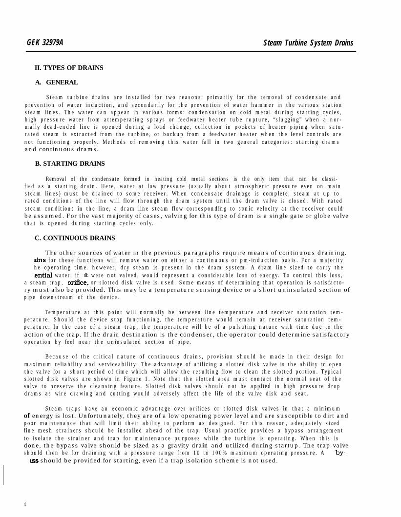
GEK 32979A Steam Turbine System Drains
II. TYPES OF DRAINS
A. GENERAL
Steam turbine drains are installed for two reasons: primarily for the removal of condensate andprevention of water induction, and secondarily for the prevention of water hammer in the various stationsteam lines. The water can appear in various forms: condensation on cold metal during starting cycles,high pressure water from attemperating sprays or feedwater heater tube rupture, “slugging” when a nor-mally dead-ended line is opened during a load change, collection in pockets of heater piping when satu-rated steam is extracted from the turbine, or backup from a feedwater heater when the level controls arenot functioning properly. Methods of removing this water fall in two general categories: starting dramsand continuous drams.
B. STARTING DRAINS
Removal of the condensate formed in heating cold metal sections is the only item that can be classi-fied as a starting drain. Here, water at low pressure (usually about atmospheric pressure even on mainsteam lines) must be drained to some receiver. When condensate drainage is complete, steam at up torated conditions of the line will f low through the dram system until the dram valve is closed. With ratedsteam conditions in the line, a dram line steam flow corresponding to sonic velocity at the receiver couldbe assumed. For the vast majority of cases, valving for this type of dram is a single gate or globe valvethat is opened during starting cycles only.
C. CONTINUOUS DRAINS
The other sources of water in the previous paragraphs require means of continuous draining.&IS for these functions will remove water on either a continuous or pm-induction basis. For a majorityhe operating time. however, dry steam is present in the dram system. A dram line sized to carry the.ential water, if it were not valved, would represent a considerable loss of energy. To control this loss,
a steam trap, or&e. or slotted disk valve is used. Some means of determining that operation is satisfacto-ry must also be provided. This may be a temperature sensing device or a short uninsulated section ofpipe downstream of the device.
Temperature at this point will normally be between line temperature and receiver saturation tem-perature. Should the device stop functioning, the temperature would remain at receiver saturation tem-perature. In the case of a steam trap, the temperature will be of a pulsating nature with time due to theaction of the trap. If the drain destination is the condenser, the operator could determine satisfactoryoperation by feel near the uninsulated section of pipe.
Because of the critical nature of continuous drains, provision should be made in their design formaximum reliability and serviceability. The advantage of utilizing a slotted disk valve is the ability to openthe valve for a short period of time which will allow the resulting flow to clean the slotted portion. Typicalslotted disk valves are shown in Figure 1. Note that the slotted area must contact the normal seat of thevalve to preserve the cleansing feature. Slotted disk valves should not be applied in high pressure dropdrams as wire drawing and cutting would adversely affect the life of the valve disk and seat.
Steam traps have an economic advantage over orifices or slotted disk valves in that a minimumof energy is lost. Unfortunately, they are of a low operating power level and are susceptible to dirt andpoor maintenance that will l imit their ability to perform as designed. For this reason, adequately sizedfine mesh strainers should be installed ahead of the trap. Usual practice provides a bypass arrangementto isolate the strainer and trap for maintenance purposes while the turbine is operating. When this isdone, the bypass valve should be sized as a gravity drain and utilized during startup. The trap valveshould then be for draining with a pressure range from 10 to 100% maximum operating pressure. A by-
xss should be provided for starting, even if a trap isolation scheme is not used.
4

ii:
Steam Turbine Systevn Drains GEK 32979A
Fixed orifice drains provide a means of continuous draining with minimum maintenance. Experi-ence has demonstrated that a 3/ 16 in (4.76 mm) minimum size must be maintained to prevent pluggingWhen the operating pressure upstream of the orifice is high, significant reduction in flow can be obtainedby using two orifices in series.
HOLE AWAY FROM SEATWILL NOT BE
SELF CLEANING
LbI
HOLE WILL NOT BESELF CLEANING
UNSATISFACTORYVIEW “A”
3/1 6 i n ( 4 . 7 6 m m ) S L O T I NS E A T A R E A
GLOBE VALVE
S L O T T O B E 3/1 6 i n . ( 4 . 7 6 m m )MIN WHEN CLOSED
VIEW “A’
GATE VALVE
Fiiure 1. Slotted Disk Drain Valves
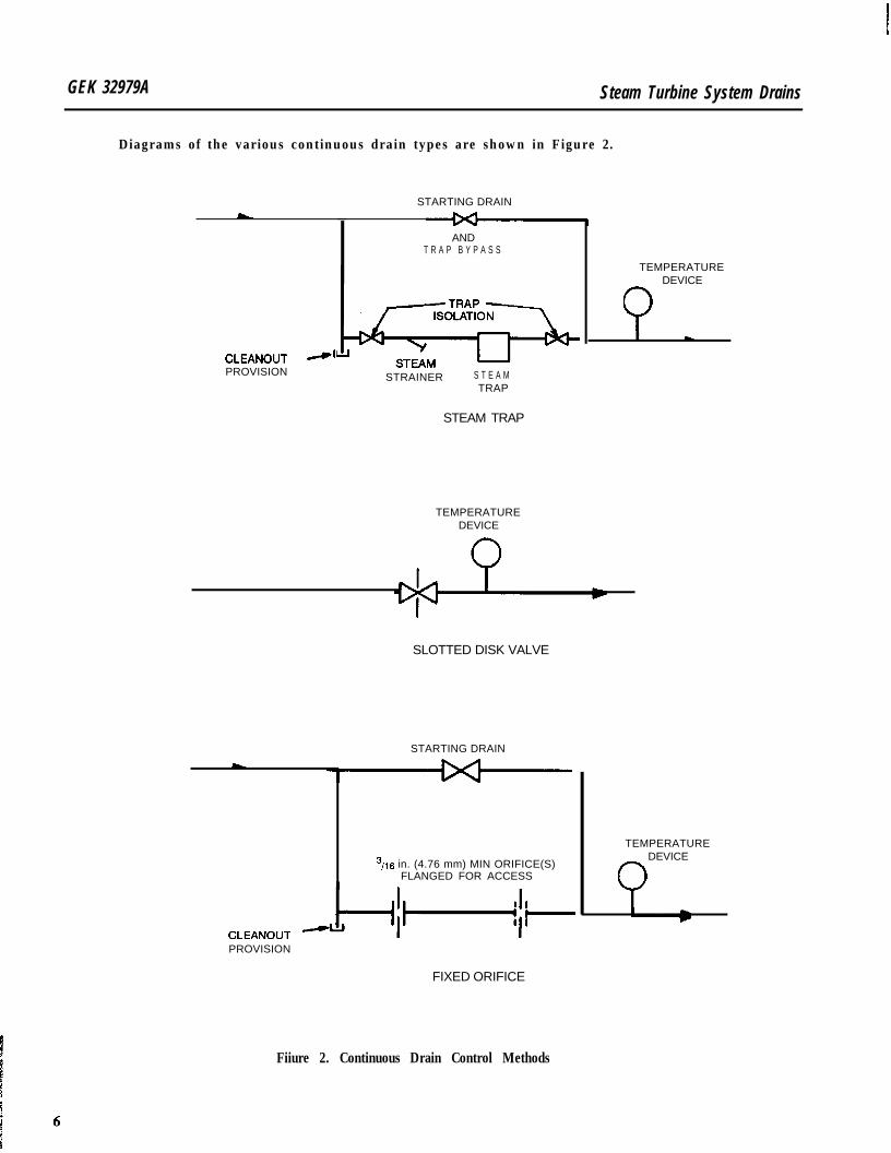
GEK 32979A Steam Turbine System Drains
Diagrams of the various continuous drain types are shown in Figure 2.
STARTING DRAINL
CLEANOUT -’PROVISION
ANDT R A P B Y P A S S
STRAINER S T E A MTRAP
TEMPERATUREDEVICE
Q
STEAM TRAP
TEMPERATUREDEVICE
SLOTTED DISK VALVE
STARTING DRAIN
3,16 in. (4.76 mm) MIN ORIFICE(S)FLANGED FOR ACCESS
CLEANOUTPROVISION
FIXED ORIFICE
Fiiure 2. Continuous Drain Control Methods
TEMPERATUREDEVICE
Q
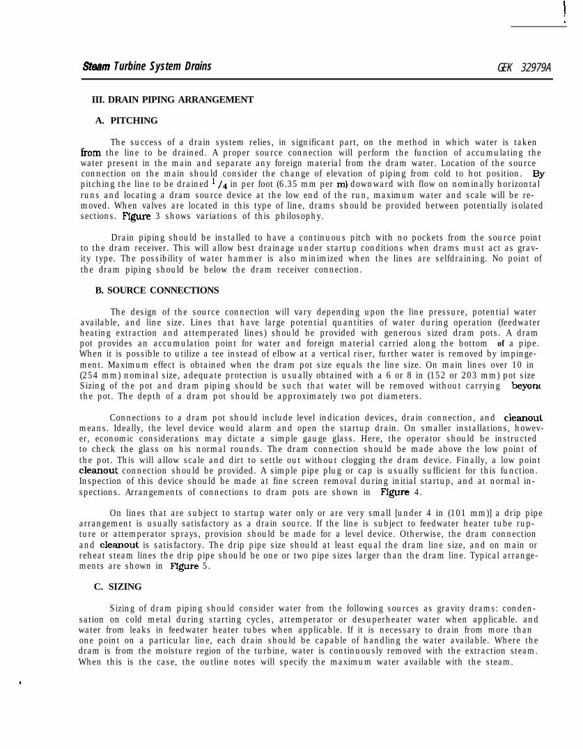
Sttwm Turbine System Drains GEK 32979A
III. DRAIN PIPING ARRANGEMENT
A. PITCHING
The success of a drain system relies, in significant part, on the method in which water is takenfrom the line to be drained. A proper source connection will perform the function of accumulating thewater present in the main and separate any foreign material from the dram water. Location of the sourceconnection on the main should consider the change of elevation of piping from cold to hot position. Bypitching the line to be drained ’ /4 in per foot (6.35 mm per ml downward with flow on nominally horizontalruns and locating a dram source device at the low end of the run, maximum water and scale will be re-moved. When valves are located in this type of line, drams should be provided between potentially isolatedsections. Figure 3 shows variations of this philosophy.
Drain piping should be installed to have a continuous pitch with no pockets from the source pointto the dram receiver. This will allow best drainage under startup conditions when drams must act as grav-ity type. The possibility of water hammer is also minimized when the lines are selfdraining. No point ofthe dram piping should be below the dram receiver connection.
B. SOURCE CONNECTIONS
The design of the source connection will vary depending upon the line pressure, potential wateravailable, and line size. Lines that have large potential quantities of water during operation (feedwaterheating extraction and attemperated lines) should be provided with generous sized dram pots. A drampot provides an accumulation point for water and foreign material carried along the bottom of a pipe.When it is possible to utilize a tee instead of elbow at a vertical riser, further water is removed by impinge-ment. Maximum effect is obtained when the dram pot size equals the line size. On main lines over 10 in(254 mm) nominal size, adequate protection is usually obtained with a 6 or 8 in (152 or 203 mm) pot sizeSizing of the pot and dram piping should be such that water will be removed without carrying beyoncthe pot. The depth of a dram pot should be approximately two pot diameters.
Connections to a dram pot should include level indication devices, drain connection, and cleanoutmeans. Ideally, the level device would alarm and open the startup drain. On smaller installations, howev-er, economic considerations may dictate a simple gauge glass. Here, the operator should be instructedto check the glass on his normal rounds. The dram connection should be made above the low point ofthe pot. This will allow scale and dirt to settle out without clogging the dram device. Finally, a low pointcleanout connection should be provided. A simple pipe plug or cap is usually sufficient for this function.Inspection of this device should be made at fine screen removal during initial startup, and at normal in-spections. Arrangements of connections to dram pots are shown in Figure 4.
On lines that are subject to startup water only or are very small [under 4 in (101 mm)] a drip pipearrangement is usually satisfactory as a drain source. If the line is subject to feedwater heater tube rup-ture or attemperator sprays, provision should be made for a level device. Otherwise, the dram connectionand cleanout is satisfactory. The drip pipe size should at least equal the dram line size, and on main orreheat steam lines the drip pipe should be one or two pipe sizes larger than the dram line. Typical arrange-ments are shown in Figure 5.
C. SIZING
Sizing of dram piping should consider water from the following sources as gravity drams: conden-sation on cold metal during starting cycles, attemperator or desuperheater water when applicable. andwater from leaks in feedwater heater tubes when applicable. If it is necessary to drain from more thanone point on a particular line, each drain should be capable of handling the water available. Where thedram is from the moisture region of the turbine, water is continuously removed with the extraction steam.When this is the case, the outline notes will specify the maximum water available with the steam.
.
GEK 32979A
Steam Turbine System Drains
SOURCESSOURCES
HORIZONTAL RUNS WITH HEAT-E R
ABOVE TURBINE CONNECTION
H O R I Z O N T A L R U N SWITH
LOW POINTS IN PIPING
H O R I Z O N T A L R U N S W I T H
Figure 3. Pitch and Drain of Horizontal Runs
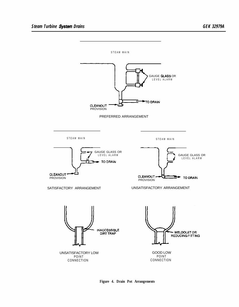
Steam Turbine estem Drains GEK 32979A
S T E A M M A I N
GAUGE GLASS ORL E V E L A L A R M
PROVISION
PREFERRED ARRANGEMENT
S T E A M M A I N
GAUGE GLASS ORL E V E L A L A R M
CLEANOUT -uPROVISION
SATISFACTORY ARRANGEMENT
S T E A M M A I N
GAUGE GLASS ORL E V E L A L A R M
PROVISION
UNSATISFACTORY ARRANGEMENT
UNSATISFACTORY LOWP O I N T
CONNECTION
GOOD LOWP O I N T
CONNECTION
Figure 4. Drain Pot Arrangements
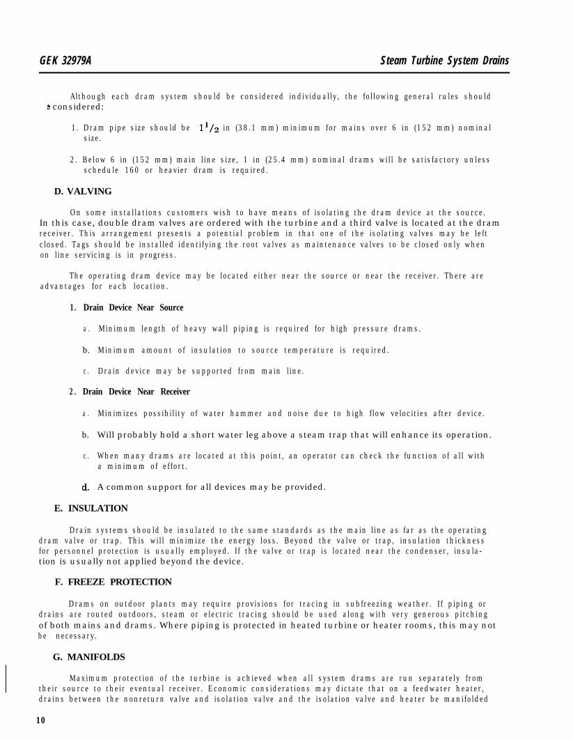
GEK 32979A Steam Turbine System Drains
Although each dram system should be considered individually, the following general rules shoulde considered:
1. Dram pipe size should be 1’/2 in (38.1 mm) minimum for mains over 6 in (152 mm) nominalsize.
2. Below 6 in (152 mm) main line size, 1 in (25.4 mm) nominal drams will be satisfactory unlessschedule 160 or heavier dram is required.
D. VALVING
On some installations customers wish to have means of isolating the dram device at the source.In this case, double dram valves are ordered with the turbine and a third valve is located at the dramreceiver. This arrangement presents a potential problem in that one of the isolating valves may be leftclosed. Tags should be installed identifying the root valves as maintenance valves to be closed only whenon line servicing is in progress.
The operating dram device may be located either near the source or near the receiver. There areadvantages for each location.
1 . Drain Device Near Source
a . Minimum length of heavy wall piping is required for high pressure drams.
b. Minimum amount of insulation to source temperature is required.
c . Drain device may be supported from main line.
2 . Drain Device Near Receiver
a . Minimizes possibility of water hammer and noise due to high flow velocities after device.
b. Will probably hold a short water leg above a steam trap that will enhance its operation.
c . When many drams are located at this point, an operator can check the function of all witha minimum of effort.
d. A common support for all devices may be provided.
E. INSULATION
Drain systems should be insulated to the same standards as the main line as far as the operatingdram valve or trap. This will minimize the energy loss. Beyond the valve or trap, insulation thicknessfor personnel protection is usually employed. If the valve or trap is located near the condenser, insula-tion is usually not applied beyond the device.
F. FREEZE PROTECTION
Drams on outdoor plants may require provisions for tracing in subfreezing weather. If piping ordrains are routed outdoors, steam or electric tracing should be used along with very generous pitchingof both mains and drams. Where piping is protected in heated turbine or heater rooms, this may notbe necessary.
G. MANIFOLDS
Maximum protection of the turbine is achieved when all system drams are run separately fromtheir source to their eventual receiver. Economic considerations may dictate that on a feedwater heater,drains between the nonreturn valve and isolation valve and the isolation valve and heater be manifolded
10
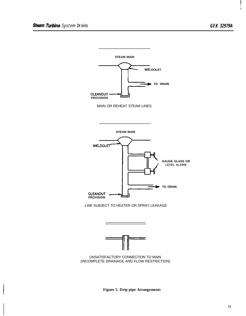
Shim Tutiine System Drains GEK 32979A
STEAM MAIN
WELDOLET-T-/ TO DRAIN
CLEANOUTPROVISION -lu
MAIN OR REHEAT STEAM LINES
STEAM MAIN
GAUGE GLASS ORLEVEL ALARM
TO DRAIN
CLEANOUTPROVISION
LINE SUBJECT TO HEATER OR SPRAY LEAKAGE
UNSATISFACTORY CONNECTION TO MAIN(INCOMPLETE DRAINAGE AND FLOW RESTRICTION)
Figure 5. Drip pipe Arrangements
11
GEK 32979A Steam Turbine System Drains
gether (when flow normally passes through the nonreturn valve before the isolation valve as in Figure. On some two stop valve or two reheat stop valve installations, similar combining may be desired.&her information on combined drams will be found under Section V, Recommendations for Specific
Lines. In no case should drams be combined that take sources at different pressure levels or at differentelevations at the same pressure level. The area of the combined line should be at least equal to that ofthe separate feeders. Where the junction is made from the two sources, it should be of a lateral type indirection of drain flow. Various arrangements of combined drains are shown in Figure 6.
In many cases i t is not possible to make a separate entrance connection at the dram receiver ves-sel(s) for each dram entering. In this case, an extension manifold or “porcupine” is often employed. De-sign of this manifold must satisfy the following criteria:
1 . Manifold pressure must not be greater than 2 in (50.8 mm) Hg above receiver pressure undermaximum dram steam flow conditions.
2. Discharge through manifold must not impinge on condenser tubes or expansion joints.
3. Discharge must not adversely affect adjacent manifold or condenser operation.
Although each application should be studied on its own, the following general rules should beobserved as minimum requirements:
1 . Provision should be made for verifying pressure in the manifold at initial startup and changesmade if the pressure with full flow is greater than 2 in (50.8 mm) Hg above receiver pressure.
2. Connections to the manifold should be of the lateral type to minimize tendency of backflow.
3. Cross sectional area of the manifold should be approximately 10 times the sum of areas ofentering drams.
4. Baffle discharge area should be at least 1.5 times the area of the manifold.
5. The length of manifold should be kept to a minimum with a straight entrance to the receiverpreferred.
6. Turbine system’ drains should not be manifolded with heater drams.
7. Drams from the highest pressure source should be connected furthest from the receiver.
8 . Where practical, manifolds containing drams from the turbine side of nonreturn valves shouldbe separate from manifolds containing drams from the heater side of the nonreturn valves.
Typical arrangements of manifolds are shown in Figure 7.
12
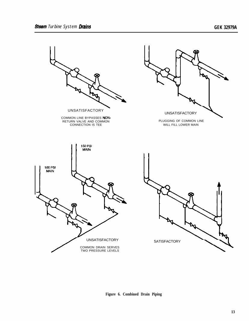
Steam Turbine System Drains GEK 32979A
UNSATISFACTORY -
COMMON LINE BYPASSES NON-RETURN VALVE AND COMMON
CONNECTION IS TEE
UNSATISFACTORY
COMMON DRAIN SERVESTWO PRESSURE LEVELS
UNSATISFACTORY
PLUGGING OF COMMON LINEWILL FILL LOWER MAIN
SATISFACTORY
\
Figure 6. Combined Drain Piping
13
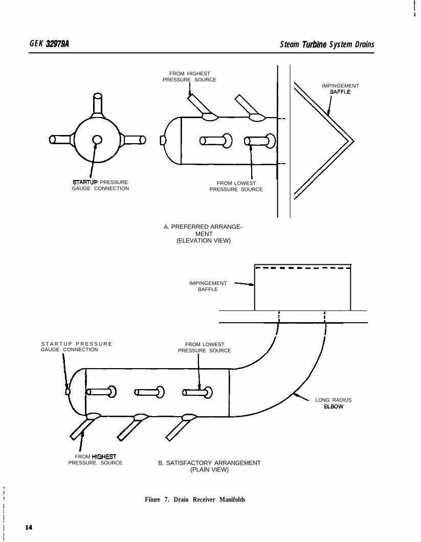
GEK 32979A Steam Tunbne System Drains
STARTUP PRESSUREGAUGE CONNECTION
FROM HIGHESTPRESSURE SOURCE
FROM LOWESTPRESSURE SOURCE
IMPINGEMENT
A. PREFERRED ARRANGE-MENT
(ELEVATION VIEW)
c------- -B-w
IMPINGEMENT -BAFFLE
S T A R T U P P R E S S U R EGAUGE CONNECTION
FROM LOWESTPRESSURE SOURCE
LONG RADIUS
FROM tl lGtiESTPRESSURE SOURCE B. SATISFACTORY ARRANGEMENT
(PLAIN VIEW)
Fiiure 7. Drain Receiver Manifolds
Steam Tutiine System Drains GEK 32979A
IV. DRAIN DESTINATIONS
Drains from various sources in a turbine should be routed to receivers suited to the intendedservice. A brief discussion of the common receivers follows.
A. BLOWDOWN TANK
This vessel is primarily used as a receiver for boiler drams. Its use for steam turbine system dramsmust be restricted to main steam leads and the before seat dram of the main stop valve(s). Design ofthis vessel is usually based on a maximum pressure of 3 to 5 psig [20-34 kPa(gauge)] 10.2-0.4 kg/cm2(gauge)] with a generous sized vent to atmosphere. With the maximum pressure in the tank, watermust dram by gravity from the before seat stop valve drain or any other low point to the tank. The designof this vessel should not overlook the fact that drams can be open for long periods, thereby dissipatingconsiderable energy. Adequate cooling should be provided.
B. ATMOSPHERIC RECEIVER
Lines that are not subject to vacuum may be drained to an atmospheric receiver. This is a vesselsimilar to a blowdown tank but is kept separate to eliminate the possibility of steam bypassing the stopvalve into the turbine. Again, the maximum pressure in the vessel is 3 to 5 psfg [20-34 kPa(gauge)](0.2-0.4 kg/cm2 (gauge)] with agenerous sized vent. The elevation must be such that all low point drainswill flow by gravity to this tank when it is operating at maximum pressure. On some installations withlow headroom this tank is located below grade and the condensate is recovered by pumping. Means ofdissipating the energy available for long periods of low load operation should be provided.
C. CONDENSER
On condensing turbines the majority of turbine system drams are brought to this destinationThis is necessary, as under starting conditions vacuum exists up to the inlet control valves on all unit:and on full arc starting units, to the main stop valves. Were these drains brought to an atmosphericreceiver, air would be brought into the turbine and condensate formed in warming the machine wouldnot be removed.
Ideally, all drams would be brought in through separate connections at the condenser. Economi-cal considerations usually limit this practice though, and “porcupines” are substituted. The entrancepoint of all drams to the condenser must be above the maximum hot well level.
Except for applications with once through steam generators (where special provisions are madein the condenser for cooling), before seat drams from main stop valves must not be routed to the con-denser. Long warming cycles and low load operation could overheat the low pressure turbine casingcausing misalignment.
On installations with very low headroom, it may be necessary to utilize a flash tank to obtain nec-essary pitching of dram piping. Here, generous sized vents should be provided to maintain essentiallycondenser pressure. Drainage from this type of tank is usually a pump controlled by tank level. A com-pletely independent second pumping system should be provided.
D. OPEN FUNNEL
Certain types of turbine drams are routed to open funnels for either anti-syphoning or telltalepurposes. Many stop valves, for instance, utilize a stem back seat. The outer leakoff from the stem isusually routed to an open funnel allowing the operator to verify condition of this back seat. Any steamvisible during normal operation would indicate trouble. During starting and testing cycles, considerablesteam is available at this funnel, so they should be located away from primary personnel areas. The fun-nel can be connected to either an atmospheric receiver or a sewer connection. On some smaller installatfons an open funnel is used as a stop valve before seat dram.
15
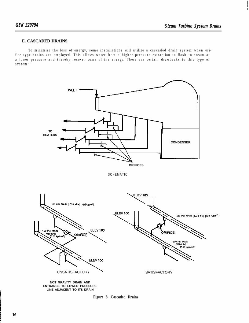
GEK 32979A Steam Turbine System Drains
E. CASCADED DRAINS
To minimize the loss of energy, some installations will utilize a cascaded drain system when ori-fice type drains are employed. This allows water from a higher pressure extraction to flash to steam ata lower pressure and thereby recover some of the energy. There are certain drawbacks to this type ofsystem:
TOHEATERS
CONDENSER
150 PSI MAli! [lo34 kPa] [lo.5 kfgfi
. ELEVlOO
:ICE
UNSATISFACTORY \
NOT GRAVITY DRAIN ANDENTRANCE TO LOWER PRESSURE
LINE ADJACENT TO ITS DRAIN
ORIFICES
S C H E M A T I C
150 PSI MAIN [10&l kPa] [lo.5 k/gm*]
100 PSI MAIN
SATISFACTORY
Figure 8. Cascaded Drains
Steam Turbine System Drains GEK 32979A
1. Large quantities of water from one extraction (ruptured feedwater tube) would become available to the next lower pressure extraction. This would in turn overload the following extractiondram and further.
2 . When a particular feedwater heater is out of service, drams from a higher pressure extractionmay tend to force any collected water back into the turbine at the out-of-service connection.
3 . Routing of the various drams must be such that gravity will remove the water formed duringstarting cycles. This may necessitate awkward station piping arrangements.
4. The entrance of a higher pressure dram Into an extraction line must not be adjacent to thelower pressure dram.
F-igure 8 shows various arrangements of cascaded systems.
V. RECOMMENDATIONS FOR SPECIFIC LINES
A. MAIN STEAM AND STOP VALVE
1. Steam lines between the boiler and main stop valve(s) should be drained without reliance onthe stop valve before seat dram. These are startup drams. Where there are two main stopvalves, the before seat drams could be manifolded together after the dram valve.
2. Drams from customer steam line and the stop valve before seat area must not be connectedto the same receiver as any other steam turbine system drams. Otherwise. a potential sourceof steam would exist that could bypass the emergency valve.
3. It is improbable that any device could act fast enough to prevent water entering the turbinein the event of a water slug passing down the steam line. Maximum protection against thistype of failure is served by an initial pressure limiter associated with the turbine governorHere, after a dead band period, the control valves are closed in proportion to the fall of mainsteam pressure.
4 . Stop valve after seat drams should be routed to the condenser on condensing units or an atmo-spheric receiver on noncondensing units. If more than one stop valve is used or if there arelow points in the steam lead between the stop valve and control valves, these drams can bemanifolded together after the dram valve. These drams are considered starting drams.
B. SHELL LOW POINTS
On many units it is necessary to dram low points of the high pressure shell during starting cycles.These starting drams should be run individually to condenser pressure on condensing units or an atmo-spheric receiver on noncondensing units. Should low points exist or moisture be present in the steampath on low pressure section, oriflced drams will be included with the inner barrel to dram directly tothe condenser or low pressure extraction.
C. EXTRACTIONS
1 . Experience has demonstrated that nonreturn valves tend to distort when water comes in con-tact with them. This water will then leak past the seat area and may enter the turbine if notremoved. For this reason, dram pots should be provided on the turbine side of nonreturnvalves. Pots should also be provided on the heater side if the one rises above the nonreturnvalve in route to the heater.
2 . Dram provisions on the turbine side of nonreturn valves should consider the water that couldleak by a distorted nonreturn valve if a feedwater heater tube ruptured. In this event, watershould not rise to the level of the turbine shell connection. This dram should be opened fullyupon high level indication of the drain pot.
17
GEK 32979A Steam Turbine System Drains
3 . Extractions from high pressure shells usually operate significantly above saturation tempera-ture. Temperature devices located in the piping between the heater and the turbine connectionwill indicate potential malfunction by dropping to saturation temperature. Util ization of thisinformation may prevent a water induction incident.
4 . h-ox&ion for continuous dram must be made on all extraction lines. Where the full load tem-perature of the extracted steam has more than 100°F (373°C) superheat, a trap type dramcontroller can be used to conserve energy. When the full load temperature of extracted steamhas less than 100°F (37.8%) superheat, orifice or slotted disk valve continuous drains shouldbe employed.
5. When water is available as a result of an extraction in the wet region of a turbine, drainagemust be provided by an orifice. The turbine outline notes will specify the amount of water avail-able.
6. When a turbine is designed with automatically controlled extractions. drains on the line sideof the nonreturn valves may be routed to an atmospheric receiver. Drams on the turbine sideof nonreturn valves and all uncontrolled extractions must be routed to the condenser on con-densing units or an atmospheric receiver on noncondensing units.
7. When a turbine is designed for automatic extraction/admission operation, the before seatdram of the trip throttle valve should be drained to an atmospheric receiver. The after seatdram should be routed to the condenser on condensing turbine or an atmospheric receiveron noncondensing turbines. Other extractions should be handled as mentioned in the preced-ing paragraphs.
D. COLD REHEAT
1 . In addition to the potential water from a ruptured feedwater heater tube, cold reheat lines arealso subject to leakage from a reheat attemperating station. Drams from the low points of thecold reheat lines should consider the flow that could be present upon failure of the attempera-tor control valve without fluid reaching the turbine shell. These drains should be 2 in (50.8mm) minimum size and be routed to the condenser.
2 . Dram pots should be installed at the low point of each cold reheat line coming from the turbine.A level alarm should be provided with these pots.
3 . Drams on the cold reheat are normally considered startup drams, but should be opened auto-matically at turbine tripouts and during shutdowns. This dram should also be opened uponindication of water in the dram pot(s).
4 . A temperature device should be installed at the low point and close to the turbine on each coldreheat line. This will serve as a water detection thermocouple.
E. HOT REHEAT AND REHEAT VALVES
1. Hot reheat steam lines between the reheater and combined reheat valves should be drainedwithout reliance on the combined valve before seat drams. Since the reheater is under vacuumat startup conditions, these drams must be routed to the condenser. When there are two com-bined reheat valves at the same operating pressure, the before seat drams could be manifoldedtogether after the dram valves. These are startup drains.
2 . After seat drams on combined reheat valves operating at the same pressure may be manifoldedtogether after the dram valves. These startup drams must be run to the condenser. The afterseat drains will dram any steam lines between the combined reheat valves and the turbineshell.
Steam Turbine System Drains GEK 32979A
F. NONCONDENSING TURBINE EXHAUST
A dram pot should be provided on the turbine side of any isolating or check valve on noncondensing turbine exhausts. If desuperheaters are utilized in this line, a level alarm must be provided and thedram valve automatically opened on level signal. This dram is considered a startup drain and shouldbe routed to an atmospheric receiver.
G. GLAND SEAL PIPING
1 . Steam seal piping furnished with the turbine is provided with slotted disk valves for low pointdrams. If necessary due to configuration. more than one low point drain will be used. Thesecontinuous drams can be routed to either the condenser or, if elevations allow gravity drain-ing, an atmospheric receiver.
2. Excess steam from the steam seal regulator is unloaded to either the condenser or low pres-sure heater. Where this line is run with turbine furnished piping, low points outside the ex-haust hood will be provided with slotted disk valves. This continuous drain should be routedto the condenser.
In some cases, this unloading line is furnished with the station piping. When its routing in-cludes portions inside the condenser neck to a low pressure heater, this piping must be keptas short as possible. The action of exhaust steam over this line acts as a condenser on thedumped steam. The end connection of this line should be made as close to the heater as possi-ble to minimize any tendency for moisture to m-enter the turbine. It should be pitched l/4in per foot (6.35 mm per ml to an orificed or slotted disk continuous dram outside the condens-er.
3. Gland evacuation piping furnished with the turbine will, whenever possible, be made selfdraining to the gland evacuation device. Should station arrangement make this impossibleany low points could be drained through a 24 in (609 mm) loop seal to an open funnel. Provision must be made for filling this loop.
4. When discharge from the gland evacuation device is recovered it can be either to an atmo-spheric receiver or through a loop seal and trap to the condenser.
5. If a gland condenser is used as the evacuation device, an accessible funnel should be usedas a telltale to indicate severe leakage or rupture of a tube, or plugging of the normal drammeans. If desired, this funnel could be routed to an atmospheric receiver.
H. STANDBY STEAM SOURCES
Many turbines require steam supply for either auxiliary steam-driven oil pumps or steam sealmakeup. The nature of this equipment is such that at normal operating conditions of speed and load,no steam is required. This sets up a dead-ended line that could allow condensation to occur if properdrainage provisions are not made. Then, on a load reduction or tripout, steam is required for the auxilia-ries. If water is present in the steam seal makeup supply, quenching of the turbine shaft and resultingcracking may occur. Water in the supply to the auxiliary steam pump may slow the pump accelerationor seriously damage the pump, either case would eliminate this critical source of lube oil supply. Designof these lines should consider the following:
1. Under conditions of no flow in the auxiliary line, the temperature of fluid in the line will fallto that of saturation. Condensate will then form due to heat loss through insulation. Designmust allow this condensate to be removed without being picked up at times when sudden de-mand for the atndliary steam is present.
2. Takeoff from the supply main should be on the side or the top of the line. If ossible. the auxil-iary supply should pitch continuously upward from this point to the device P/4 in per foot (6.35mm per m). This would make the line self-draining.
19
GEK 32979A Steam Turbine System Drains
3. Where continuous pitching cannot be employed, low points must be continuously drained.This could be controlled by either a steam trap or orifice.
4. WhereP
ortions of the auxiliary supply can be made self-draining, the pipe size should be atleast 1 /2 in (38.1 mm) to facilitate drainage.
5. On reheat turbines using an auxiliary supply at inlet pressure, maximum protection couldbe obtained by draining the low point through two orifices in series to the cold reheat line.
VI. OPERATION OF DRAINS
In the following discussion “drains” will include positive shutoff valves, slotted disk valves, andsteam trap and fIxed orifice bypass valves.
During normal operation, steam turbine system drains, except the main steam supply ahead ofthe main stop valve disk, should be opened before vacuum is broken when the unit is shut down. Thesedrams should remain open while the unit is down.
Upon startup, all drains should be opened wide. After synchronizing, drams that are at mainsteam pressure (stop valve before seat drain on full arc units: before and after seat drains on non fullarc units) can be closed to approximately 3/4 turn open. When 15% load is reached (or transfer to partialarc admission is made on full arc units) all drains except those associated with the lowest pressure heat-er may be completely closed. Drams associated with the lowest pressure heater should not be closeduntil unit load is above 30%.
When a heater is taken out of service, the drains on the turbine side of nonretum and blockinglives should be opened. This will prevent the formation of water in the dead-ended piping.
Action upon detection of water entering an operating turbine should vary with the entering point.LII all cases, drains associated with the entering point should be opened and the event noted in the opera-tor’s log. If the entering point is other than the lowest pressure feedwater extraction, the unit shouldbe kept on the line as long as vibration and differential expansion are normal. When the entering pointis the low pressure feedwater extraction, the unit should be taken off the line immediately.
Drams on the heater side of nonreturn valves should be opened on a high heater level indication.When remotely operated drams are provided, this opening action should be automatic. On systems thatdo not have a level alarm with the drip pot on the turbine side of nonreturn valves, this drain shouldalso be opened on high heater level indication. When the drip pot has a level alarm, this can be usedas the initiating signal for opening the drain.
Drams on cold reheat piping should be opened on decreasing load when the unit is taken off theline. Steam flow at this point is low enough that attemperator water may not be carried through intothe reheater and severe water hammer could result if accumulated.
VII. MAINTENANCE AND TESTING
All drain devices (valves, orifices, traps) should be functionally tested on a monthly basis and dis-crepancies corrected. This may be done by measuring temperature on both sides of the drain. Assumingthe drain is to the condenser, the temperature downstream of the drain should be between the line tem-perature and condenser temperature. A permanent drop to condenser temperature would indicate anonfunctioning drain. Periodically, bypasses or slotted disk drains should be opened for a short periodof time to clear any accumulated dirt.
If periodic testing of dram indicates the device is not functioning properly, its bypass should beopened fully until proper operation is resumed.
2 0
When double drain valves are utilized, the root valves must be opened after maintenance is cornpleted. Caution warnings should be included in plant operating manuals so that these valves will no1be inadvertently left closed.
All cleanout openings, strainers and fixed orifices should be inspected at fine screen removal dur-ing the initial startup. It is during this period that most foreign material is likely to build up. These areasshould also be inspected during all normal turbine outages.
VIII. DESIGN INFORMATION
During the design phase of a turbine generator, various design information is provided for Lynn-built General Electric turbines. This will be in the form of either Reference Publication or Drawings.
A. REFERENCE PUBLICATIONS
1. Extraction System Requirements
Discussion includes the location of nonreturn valves for minimizing entrained energy and ar-rangement of piping and controls to minimize water induction.
B. DRAWINGS
1. Outline Notes
Specifies the potential water available with extraction steam from the moisture region of tur-bines.
2. Gland Condenser Specifwation
Specifies flow on turbines utilizing a gland condenser for evacuation.
3. Pressure Th3nsducer Outline
Indicates diagram for connection and locates dram provision on transducer. An open funnelshould be provided near the transducer to allow visual observation of the dram during blow-down periods. This drawing title is used on electrohydraulically controlled turbine only.
4 . Control Connections - Pressure Governor
Provides the information as the pressure transducer outline for turbines with gear pump me-chanical control systems.
5 . Piping Steam or piping Oil and Steam
The majority of customer dram connections are located and identifkd on the Piping Steam orPiping Oil and Steam drawing. Included on this drawing in tabulated form are fluid identifica-tion, maximum pressure and temperature, flow when of a continuous nature, connection andvalving data, and identification of the destination. Pressure governor connections for mechan-ically controlled units with a centrifugal pump are located on this drawing.
Dram destinations on this drawing are classified under the following codes:
code I Main Stop Valve before Seat Drains - Must not be connected to same receiver as anyother turbine drams.
21

Steam Turbine System Drains
Code II General Turbine System Drains - Must be connected to condenser on condensingunits or atmospheric receiver on noncondensing units.
Code III OptinaZ Destination - Atmospheric receiver is satisfactory when headroom will notrestrict gravity draining under maximum receiver pressure. Connection to condensergives best drainage.
Code IV TeZUuZes and Observation Drains - Open funnel should be provided in accessible loca-tion. Although a common funnel may be util ized, piping from each source to the fun-nel must be separate.
GE Industrial & Power Systems
Reformat (3/91)
General Eleciric ConpanyOne River Road Schenectady: NY 12345518.385.2211 TX: 145354
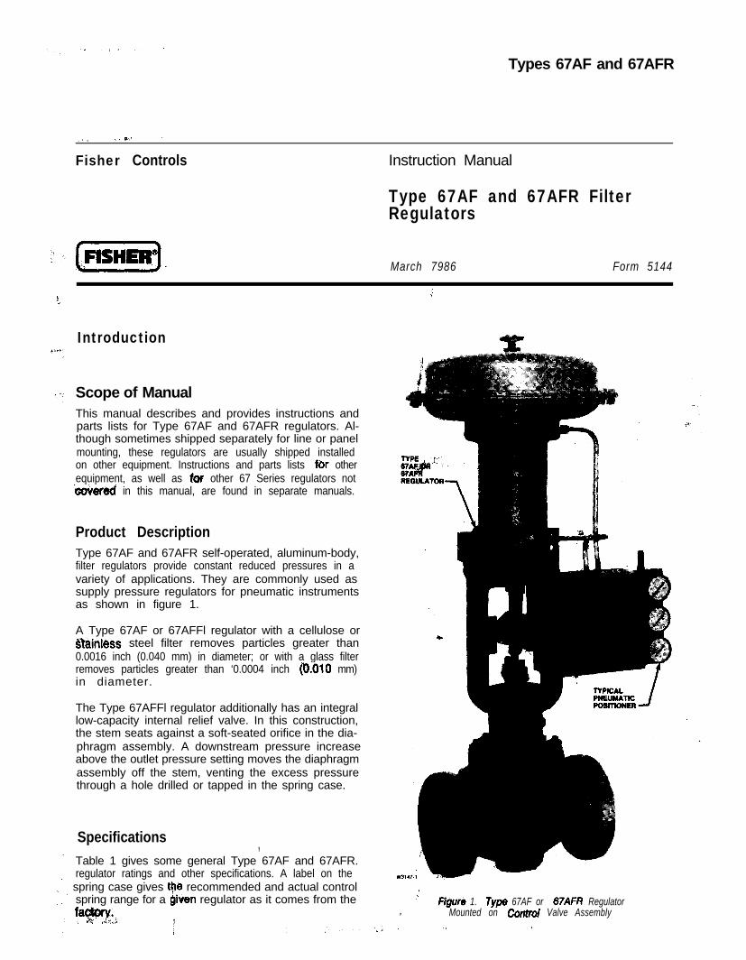
Types 67AF and 67AFR
__, ~,*‘I I.
Fisher Controls Instruction Manual
Type 67AF and 67AFR FilterRegulators
March 7986 Form 5144
Introduction
Scope of ManualThis manual describes and provides instructions andparts lists for Type 67AF and 67AFR regulators. Al-though sometimes shipped separately for line or panelmounting, these regulators are usually shipped installedon other equipment. Instructions and parts lists Rx otherequipment, as well as for other 67 Series regulators notwwered in this manual, are found in separate manuals.
Product DescriptionType 67AF and 67AFR self-operated, aluminum-body,filter regulators provide constant reduced pressures in avariety of applications. They are commonly used assupply pressure regulators for pneumatic instrumentsas shown in figure 1.
A Type 67AF or 67AFFl regulator with a cellulose orr%inless steel filter removes particles greater than0.0016 inch (0.040 mm) in diameter; or with a glass filterremoves particles greater than ‘0.0004 inch (6010 mm)in diameter.
The Type 67AFFl regulator additionally has an integrallow-capacity internal relief valve. In this construction,the stem seats against a soft-seated orifice in the dia-phragm assembly. A downstream pressure increaseabove the outlet pressure setting moves the diaphragmassembly off the stem, venting the excess pressurethrough a hole drilled or tapped in the spring case.
Specifications ,Table 1 gives some general Type 67AF and 67AFR.regulator ratings and other specifications. A label on thespring case gives 9-e recommended and actual controlspring range for a given regulator as it comes from thef~&w~, , .,c-; <;.,,; ?
,’ Figure 1. Type 67AF or 67AFR Regulator, Mounted on Controt Valve Assembly
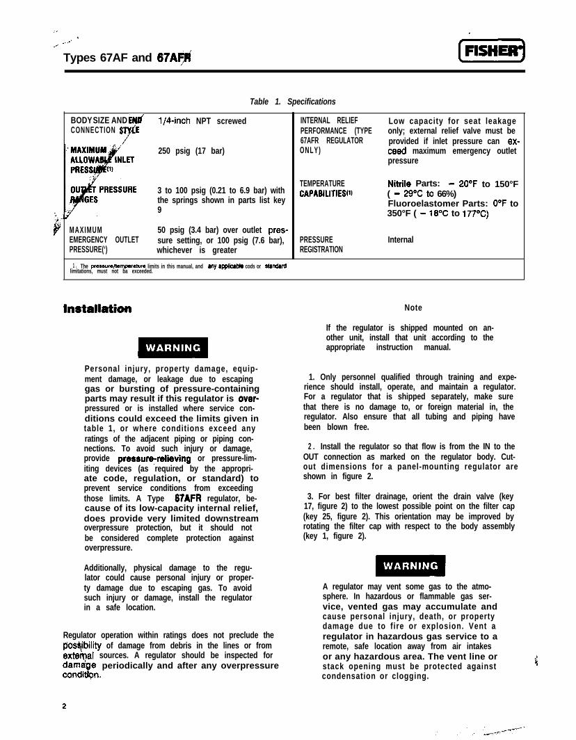
” Types 67AF and 67AFj
Table 1. Specifications
BODY SIZE AND EN(/ l/4-inch NPT screwedCONNECTION S ‘F
r”250 psig (17 bar)
3 to 100 psig (0.21 to 6.9 bar) withthe springs shown in parts list key9
MAXIMUM 50 psig (3.4 bar) over outlet pres-EMERGENCY OUTLET sure setting, or 100 psig (7.6 bar),PRESSURE(‘) whichever is greater
INTERNAL RELIEF Low capacity for seat leakagePERFORMANCE (TYPE only; external relief valve must be67AFR REGULATOR provided if inlet pressure can ex-ONLY) teed maximum emergency outlet
pressure
TEMPERATURECAPABILITIES~‘~
Nitrile Parts: - 2O“F to 150°F( - 29T to 66%)Fluoroelastomer Parts: O°F to350°F ( - 16’C to 177’C)
PRESSUREREGISTRATION
Internal
1 . The prerrure/temperature limits in this manual, and my apptkabta cods or stanQadlimitations, must not ba exceeded.
Personal injury, property damage, equip-ment damage, or leakage due to escapinggas or bursting of pressure-containingparts may result if this regulator is over-pressured or is installed where service con-ditions could exceed the limits given intable 1, or where conditions exceed anyratings of the adjacent piping or piping con-nections. To avoid such injury or damage,provide pressure;relieving or pressure-lim-iting devices (as required by the appropri-ate code, regulation, or standard) toprevent service conditions from exceedingthose limits. A Type 67AFR regulator, be-cause of its low-capacity internal relief,does provide very limited downstreamoverpressure protection, but it should notbe considered complete protection againstoverpressure.
Additionally, physical damage to the regu-lator could cause personal injury or proper-ty damage due to escaping gas. To avoidsuch injury or damage, install the regulatorin a safe location.
Regulator operation within ratings does not preclude theposqbility of damage from debris in the lines or fromexternal sources. A regulator should be inspected for
periodically and after any overpressure
Note
If the regulator is shipped mounted on an-other unit, install that unit according to theappropriate instruction manual.
1. Only personnel qualified through training and expe-rience should install, operate, and maintain a regulator.For a regulator that is shipped separately, make surethat there is no damage to, or foreign material in, theregulator. Also ensure that all tubing and piping havebeen blown free.
2 . Install the regulator so that flow is from the IN to theOUT connection as marked on the regulator body. Cut-out dimensions for a panel-mounting regulator areshown in figure 2.
3. For best filter drainage, orient the drain valve (key17, figure 2) to the lowest possible point on the filter cap(key 25, figure 2). This orientation may be improved byrotating the filter cap with respect to the body assembly(key 1, figure 2).
A regulator may vent some gas to the atmo-sphere. In hazardous or flammable gas ser-vice, vented gas may accumulate andcause personal injury, death, or propertydamage due to fire or explosion. Vent aregulator in hazardous gas service to aremote, safe location away from air intakesor any hazardous area. The vent line orstack opening must be protected againstcondensation or clogging.
2
4. A clogged spring case vent hole may cause theregulator to function improperly. To keep this vent holefrom being plugged (and to keep the spring case fromcollecting moisture, corrosive chemicals, or other for-eign material) orient the vent to the lowest possible pointon the spring case or otherwise protect it. Inspect thevent hole regularly to make sure it has not been plugged.Spring case vent hole orientation may be changed byrotating the spring case with respect to the body. A Type67AF or 67AFR regulator with a tapped spring case maybe remotely vented by installing obstruction-free tubingor piping into the l/Cinch NPT vent tapping. Provideprotection on a remote vent by installing a screened ventcap in the remote end of the vent pipe.
5. For use in regulator shutdown, install upstream anddownstream vent valves or provide some other suitablemeans of properly venting the regulator inlet and outletpressures.
6. If using pipe, apply a good grade of pipe compoundto the pipe threads before making the connections.
7. Install tubing or piping into the l/Cinch NPT inletconnection on the body assembly (key 1, figure 2) andalso into the l/4-inch NPT body outlet connection, un-less this connection already has been factory-piped toanother unit.
Types 6~ and 67
-,..: ( 1of pressure containing parts or explosion ofaccumulated gas, never adjust the controlspring to produce an outlet pressure higherthan the upper limit of the outlet pressurerange for that particular spring. If the de-sired outlet pressure is not within the rangeof the control spring, install a spring of theproper range according to the diaphragmparts maintenance procedure.
Note
Each regulator is factory-set for the pres-sure setting specified on the order. If nosetting was specified, outlet pressure wasfactory-set at the midrange of the controlspring.
3. If outlet pressure adjustment is necessary, monitoroutlet pressure with a gauge during the adjustmentprocedure. A standard Type 67AF or 67AFR regulator isadjusted by loosening the locknut (key 11, if used) andturning the adjusting screw or handwheel (key 10) clock-wise to increase, or counterclockwise to decrease, theoutlet pressure setting. Then, tighten the locknut (ifused) to maintain the adjustment position. On someregulators, a closing cap (key 28, not shown) must beremoved before adjustment and replaced afterward.
Startup and AdjustmentShutdown
Key numbers are referenced in figure 2.
1. With proper installatibn completed and downstreamequipment properly adjusted, slowly open the upstreamand downstream shutoff valve while using pressuregauges to monitor pressure.
2. Regulator outlet pressure may be monitored on agauge installed at some point downstream from theregulator, such as the supply pressure gauge of apneumatic instrument for which the regulator is provid-ing reduced pressure. Or, outlet pressure may be moni-tored on a gauge (key 21, not shown) installed on thebody of a regulator with a tapped side outlet. If theregulator has no gauge but the side outlet is tapped andplugged, the pipe plug (key 21, not shown) may beremoved and a gauge temporarily installed formonitoring.
To avoid personal injury, property damage,or equipment damage caused by bursting
First close the nearest upstream shutoff valve and thenclose the nearest downstream shutoff valve to vent theregulator properly. Next, open the vent valve betweenthe regulator and the downstream shutoff valve nearestto it. All pressure between these shutoff valves will bereleased through the open vent valve, since a Type67AF or 67AFR regulator remains open in response tothe decreasing downstream pressure.
Maintenance
Regulator parts are subject to normal wear and must beinspected and replaced as necessary. The frequency ofinspection and replacement of parts depends on theseverity of service conditions and upon applicablecodes and government regulations. Open the drainvalve (key 17, figure 2) periodically to empty accumulat-ed moisture from the filter cap (key 25, figure 2).
3
-__ - . -- _d’
,3&k 67AF and 67AFR[ FISHER”I
To avoid personal injury, property damage,or equipment damage caused by suddenrelease of pressure or explosion of accu-mulated gas, do not attempt any mainte-nance or disassembly without first isolatingthe regulator from system pressure andrelieving all internal pressure from theregulator.
Note
If sufficient clearance exits, the body as-sembly (key 1) may remain mounted onother equipment or in a line or panel unlessthe entire regulator will be replaced.
Key numbers are referenced in figure 2 unless other-wise noted.
Filter Element and Trim Parts1. Use a 12-point socket wrench to remove the cap
screws (key 18). Remove the filter cap and gasket (keys25 and 19).
2. The retainer assembly and filter element (keys 43and 29) may come off with the filter cap; if not, removethese parts to let the plug spring (key 6) plug spring seat(key 5) and plug/stem assembly (key 4) drop freely fromthe body.
3. Inspect the removed parts, replace as necessary,and make sure the plug seating surfaces are free fromdebris. A dirty filter element may be cleaned with solventand blown dry.
4. Apply a good grade of lubricant to the gasket (key19) before installing it. Stack the gasket, retainer assem-bly, filter element, plug spring, plug spring seat, andplug/stem assembly (keys 19,43,29,6,5, and 4) on thefilter cap (key 25). Install the filter cap with stacked partsinto the body assembly (key 1) and secure with the capscrews (key 18).
Diaphragm Parts1. Remove the closing cap if used (key 28, not shown),
loosen the locknut if used (key 11) and back out the
adjusting screw or handwheel (key 10) until compres-s i o n i s r e m o v e d f r o m t h e c o n t r o l s p r i n g(key 9).
2. Remove the machine screws (key 12) and separatethe spring case (key 2) from the body assembly (key 1).Remove the control spring seat and control spring (keys8 and 9).
3. Remove the diaphragm assembly (key 7) and in-spect the diaphragm.
4. Install the diaphragm assembly (key 7) and pushdown on it to see if the plug/stem assembly (key 4)strokes smoothly and approximately l/16 inch (2 mm).
Note
In step 5, if installing a control spring of adifferent range from the one that was re-moved, be sure to delete the spring rangeoriginally appearing on the control springlabel (key 20, not shown) and indicate thenew spring range.
5. Stack the control spring and control spring seat(keys 9 and 8) onto the diaphragm assembly (key 7).
6. Install the spring case (key 2) on the body assembly(key 1) with the vent oriented to prevent clogging orentrance of moisture. Install the machine screws (key12) and torque to 5 to 7 foot-pounds (7 to 9 Nam).
7. When all maintenance is complete, refer to thestartup and adjustment section to put the regulator backinto operation and adjust the pressure setting. Tightenthe locknut if used (key 1 l), and install the closing cap ifused (key 28, not shown).
Parts OrderingWhen corresponding with the Fisher sales office orsales representative about this regulator, include thetype number and all other pertinent information stampedon the bottom of the filter cap and on the control springlabel. Specify the eleven-character part number whenordering new parts from the following parts list.
4
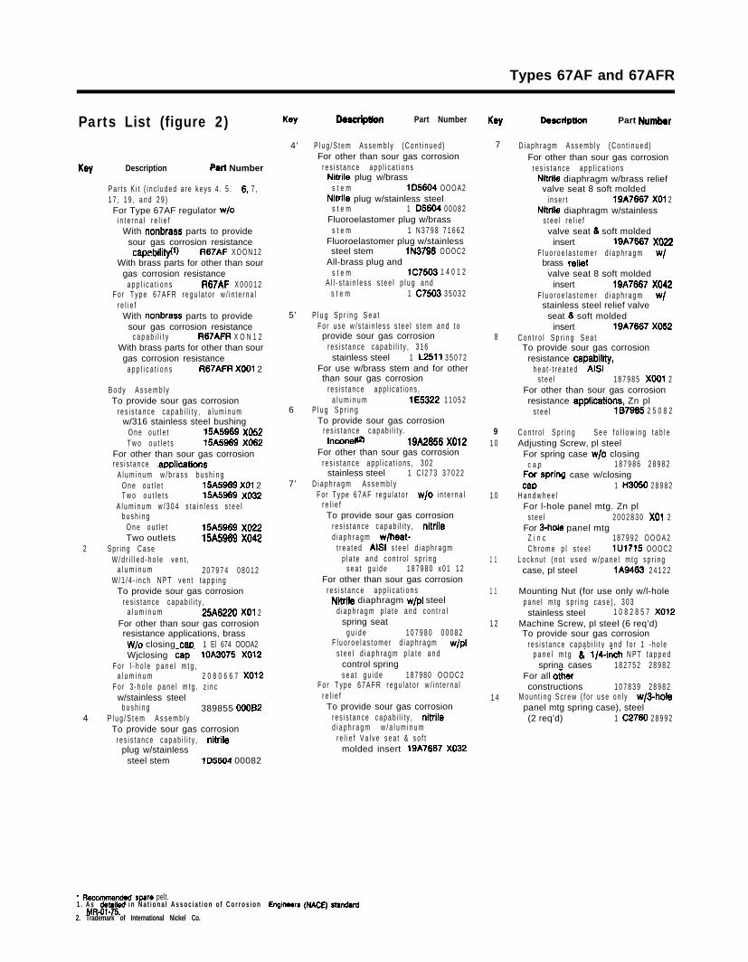
Types 67AF and 67AFR
Parts List (figure 2)
Key Description Parl Number
P a r t s K i t ( i n c l u d e d a r e k e y s 4 . 5 . 6. 7 ,1 7 , 1 9 , a n d 2 9 )For Type 67AF regulator w/o
i n t e r n a l r e l i e fWith nonbrass parts to provide
sour gas corrosion resistancecapebility(l) R67AF X O O N 1 2
With brass parts for other than sourgas corrosion resistance
a p p l i c a t i o n s R67AF X 0 0 0 1 2F o r T y p e 6 7 A F R r e g u l a t o r w / i n t e r n a l
r e l i e fWith nonbrass parts to provide
sour gas corrosion resistancec a p a b i l i t y R67AFR X O N 1 2
With brass parts for other than sourgas corrosion resistance
a p p l i c a t i o n s R67AFR X001 2
B o d y A s s e m b l yTo provide sour gas corrosion
r e s i s t a n c e c a p a b i l i t y , a l u m i n u mw/316 stainless steel bushing
O n e o u t l e t 15A5969 X052T w o o u t l e t s 15A5969 X062
For other than sour gas corrosionr e s i s t a n c e .applications
A l u m i n u m w / b r a s s b u s h i n gO n e o u t l e t 15A5969 X01 2T w o o u t l e t s 15A5969 X032
A l u m i n u m w / 3 0 4 s t a i n l e s s s t e e lb u s h i n g
O n e o u t l e t 15A5969 X022Two outlets 15A5989 X042
2 S p r i n g C a s eW / d r i l l e d - h o l e v e n t ,
a l u m i n u m 2 0 7 9 7 4 0 8 0 1 2W / 1 / 4 - i n c h N P T v e n t t a p p i n g
To provide sour gas corrosionr e s i s t a n c e c a p a b i l i t y ,
a l u m i n u m 25A6220 X01 2For other than sour gas corrosionresistance applications, brass
W/o closing cam 1 El 674 OOOA2Wjclosing cap. lOA X012
F o r l - h o l e p a n e l m t g ,a l u m i n u m 2 0 8 0 6 6 7 X012
F o r 3 - h o l e p a n e l m t g . z i n cw/stainless steel
b u s h i n g 389855 000824 P l u g / S t e m A s s e m b l y
To provide sour gas corrosionr e s i s t a n c e c a p a b i l i t y , nitrile
plug w/stainlesssteel stem lD5604 00082
Key Descrlpuon Part Number Key
4’ P l u g / S t e m A s s e m b l y ( C o n t i n u e d )For other than sour gas corrosion
r e s i s t a n c e a p p l i c a t i o n sNitrile plug w/brass
s t e m lD5604 O O O A 2Nitrile plug w/stainless steel
s t e m 1 D5604 0 0 0 8 2Fluoroelastomer plug w/brass
s t e m 1 N 3 7 9 8 7 1 6 6 2Fluoroelastomer plug w/stainlesssteel stem lN3798 OOOC2
All-brass plug ands t e m lC7503 1 4 0 1 2
A l l - s t a i n l e s s s t e e l p l u g a n ds t e m 1 C7503 3 5 0 3 2
5’ P l u g S p r i n g S e a tF o r u s e w / s t a i n l e s s s t e e l s t e m a n d t oprovide sour gas corrosion
r e s i s t a n c e c a p a b i l i t y , 3 1 6stainless steel 1 L2511 3 5 0 7 2
For use w/brass stem and for otherthan sour gas corrosion
r e s i s t a n c e a p p l i c a t i o n s ,a l u m i n u m lE5322 1 1 0 5 2
6 P l u g S p r i n gTo provide sour gas corrosion
r e s i s t a n c e c a p a b i l i t y .Inconelfs) 19A2856 X012
For other than sour gas corrosionr e s i s t a n c e a p p l i c a t i o n s , 3 0 2
stainless steel 1 C l 2 7 3 3 7 0 2 27’ D i a p h r a g m A s s e m b l y
F o r T y p e 6 7 A F r e g u l a t o r w/o i n t e r n a lr e l i e fTo provide sour gas corrosion
r e s i s t a n c e c a p a b i l i t y , nitriled i a p h r a g m w/heat-
t r e a t e d AISI s t e e l d i a p h r a g mp l a t e a n d c o n t r o l s p r i n g
s e a t g u i d e 1 8 7 9 8 0 x 0 1 1 2For other than sour gas corrosion
r e s i s t a n c e a p p l i c a t i o n sNitrile diaphragm w/p1 steel
d i a p h r a g m p l a t e a n d c o n t r o lspring seat
g u i d e 1 0 7 9 8 0 0 0 0 8 2F l u o r o e l a s t o m e r d i a p h r a g m w/p1
s t e e l d i a p h r a g m p l a t e a n dcontrol springs e a t g u i d e 1 8 7 9 8 0 O O O C 2
F o r T y p e 6 7 A F R r e g u l a t o r w / i n t e r n a lr e l i e fTo provide sour gas corrosion
r e s i s t a n c e c a p a b i l i t y , nitriled i a p h r a g m w / a l u m i n u m
r e l i e f V a l v e s e a t & s o f tmolded insert 19A7687 X032
7
8
91 0
1 0
1 1
1 1
1 2
1 4
DWCriptlOll Part Numbr
D i a p h r a g m A s s e m b l y ( C o n t i n u e d )For other than sour gas corrosion
r e s i s t a n c e a p p l i c a t i o n sNitrile diaphragm w/brass reliefvalve seat 8 soft molded
i n s e r t 19A7867 X01 2Nitrile diaphragm w/stainless
s t e e l r e l i e fvalve seat 8 soft molded
insert 19A7687 X022F l u o r o e l a s t o m e r d i a p h r a g m w/brass relief
valve seat 8 soft moldedinsert 19A7687 X042
F l u o r o e l a s t o m e r d i a p h r a g m w/stainless steel relief valve
seat 8 soft moldedinsert 19A7867 X052
C o n t r o l S p r i n g S e a tTo provide sour gas corrosion
resistance capability,h e a t - t r e a t e d AISI
s t e e l 1 8 7 9 8 5 X001 2For other than sour gas corrosionresistance appliit ions. Zn pl
s t e e l 187985 2 5 0 8 2
C o n t r o l S p r i n g S e e f o l l o w i n g t a b l eAdjusting Screw, pl steel
For spring case w/o closingc a p 1 8 7 9 8 6 2 8 9 8 2
For.spring case w/closingCaD 1 H3050 2 8 9 8 2
H a n d w h e e lFor l-hole panel mtg. Zn pl
s t e e l 2 0 0 2 8 3 0 x01 2For 3-hole panel mtg
Z i n c 1 8 7 9 9 2 O O O A 2C h r o m e p l s t e e l lU1715 OOOC2
L o c k n u t ( n o t u s e d w / p a n e l m t g s p r i n gcase, pl steel lA9463 2 4 1 2 2
Mounting Nut (for use only w/l-holep a n e l m t g s p r i n g c a s e ) , 3 0 3stainless steel 1 0 8 2 8 5 7 X012
Machine Screw, pl steel (6 req’d)To provide sour gas corrosion
r e s i s t a n c e c a p a b i l i t y a n d f o r 1 - h o l ep a n e l m t g 8 1/4-&h N P T t a p p e d
sprina cases 1 8 2 7 5 2 2 8 9 8 2For all ocherconstructions 1 0 7 8 3 9 2 8 9 8 2
M o u n t i n g S c r e w ( f o r u s e o n l y w@holepanel mtg spring case), steel(2 req’d) 1 C2780 2 8 9 9 2
* Rawmmsndad spare pelt.1 . A s detailad i n N a t i o n a l A s s o c i a t i o n o f C o r r o s i o n Engkwem (NAM) standard
M&01-75.2. Trademark of International Nickel Co.
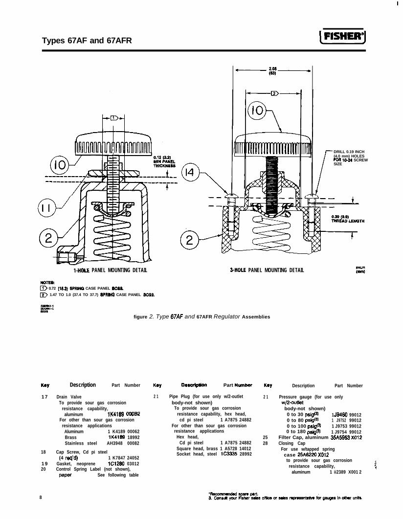
Types 67AF and 67AFR (FBSHE~J
DRILL 0.19 INCH(4.0 mm) HOLESFOR lo-24 SCREWSIZE
l-HOLE PANEL MOUNTING DETAIL WIOLE PANEL MOUNTING DETAIL
NOTEI):D 0.72 (l&3) SPRINQ CASE PANEL SOS&
D 1.47 TO 1.0 (37.4 TO 37.7) SPPRINO CASE PANEL SOSS.
figure 2. Type 67AF and 67AFR Regulator Assemblies
Key Description Part Number Key Description Part Numhr Key Description Part Number
1 7 Drain ValveTo provide sour gas corrosion
resistance capability,aluminum lK4189 OOfI62
For other than sour gas corrosionresistance applications
Aluminum 1 K4189 00062Brass lK4189 18992Stainless steel AH3948 00082
18 Cap Screw, Cd pi steel(4 req’d) 1 K7847 24052
1 9 Gasket, neoprene lC1280 0301220 Control Spring Label (not shown),
paper See following table
2 1 Pipe Plug (for use only w/2-outletbody-not shown)
To provide sour gas corrosionresistance capability, hex head,
cd pi steel 1 A7875 24882For other than sour gas corrosion
resistance applicationsHex head,
Cd pi steel 1 A7875 24882Square head, brass 1 A5728 14012Socket head, steel lC3335 28992
2 1
2528
Pressure gauge (for use onlywj2-outiet
body-not shown)0 to 30 psig@) 1 J9480 990120 to 80 psigfs) 1 J9752 990120 to 100 psigfs) 1 J9753 990120 to 180 psig(3) 1 J9754 99012
Filter Cap, aluminum 35A5983 X012Closing Cap
For use w/tapped springcase 25A8220 X012
to provide sour gas corrosionresistance capability,
aluminum 1 ii2389 X001 2
8
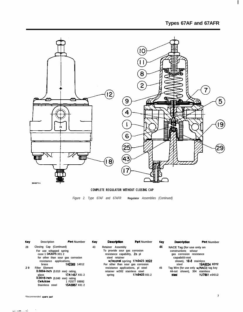
Types 67AF and 67AFR
COMPLETE REGULATOR WITHOUT CLOSING CAP
Figure 2. Type 67AF and 67AFR Regulator Assemblies (Continued)
Key Description Part Number Descfiptlon Part Number Key Dwcrlpuon Patt Number
28 Closing Cap (Continued)For use w/tapped spring
case 1 OA3075 X01 2for other than sour gas corrosion
resistance applications,brass lH2389 14012
2 9 Filter Element0.0004-inch (0.010 mm) rating,
glass 17A1457 X01 2OEl;u.W;;h (0.040 mm) rating
1 F2577 09992Stainless steel 15445987 X01 2
43 Retainer AssemblyTo provide sour gas corrosion
resistance capability, Zn plsteel retainer
w/lnconel spring 17A9423 X022For other than sour gas corrosion
resistance applications, pl steelretainer w/302 stainless steel
spring 17A9423 X01 2
44 NACE Tag (for use only onconstructions w/sour
gas corrosion resistancecapabiiii-not
shown), 18-8 stainlesssteel 19A8034 X012
45 Tag Wire (for use only w/NACE tag key44-not shown), 304 stainless
steel lU7851 x0012
*Recommended 8pare part 7
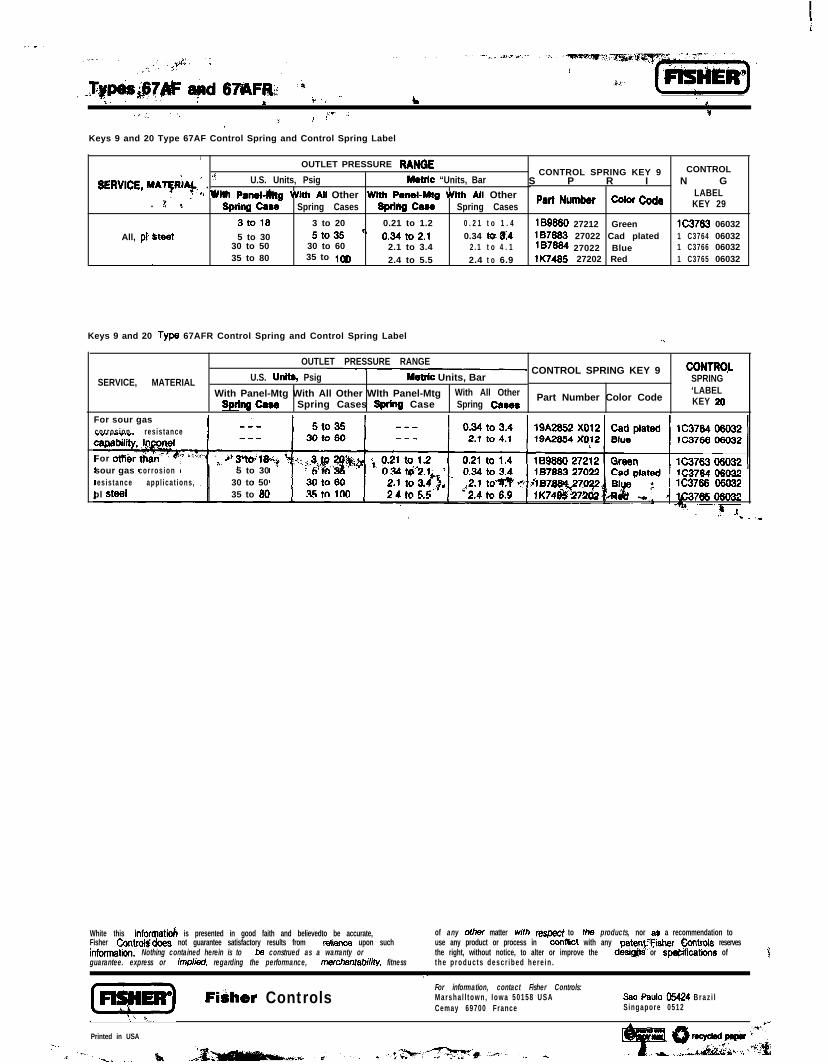
x. L1 c
[yg+gq
*._I’_ ‘, ..-. =4r , , *~
Keys 9 and 20 Type 67AF Control Spring and Control Spring Label
1OUTLET PRESSURE RANQE
SERVICE, MAqRiA& * . ”
CONTROLU.S. Units, Psig Metric “Units, Bar
CONTROL SPRING KEY 9S P R I N G
’ *” with Psnel-h&j with Ati Other with PembMtg wi Alt Other. Pq’
Pati Numbr cclcr cd0 LABELspring ceae Spring Cases Spring Case Spring Cases KEY 29
3to18 3 to 20 0.21 to 1.2 0 . 2 1 t o 1 . 4 189860 27212 Green lC3763 060325 to 30 5to35 ‘:All, pl &tee1 0.34to2.1 0.34 tq 84
30 to 50187883 27022 Cad plated 1 C3764 06032
30 to 60 2.1 to 3.4 2 . 1 t o 4 . 1 187884 27022 Blue 1 C3766 06032,, 35 to 80 35 to 1qD 2.4 to 5.5 2.4 t o 6.9 lK7485 27202 Red 1 C3765 06032
Keys 9 and 20 Type 67AFR Control Spring and Control Spring Label .”
OUTLET PRESSURE RANGE
U.S. Units, Psig@ CONTROL SPRING KEY 9 CONTROL
SERVICE, MATERIAL Metic Units, Bar SPRINGWith Panel-Mtg With All Other Wlth Panel-Mtg With All Other Part Number Color Code
‘LABELBprlnQ ceee Spring Cases Spring Case Spring Csses KEY 20
For sour gascorros ion res is tance“.,. . -“.-. ,
capabilfty
For ot?&rsour gas c o r r o s i o nres is tance app l ica t ions ,pl steel
5 to 3030 to 50 ( lC37s 0603235 to 80
m P
White this inforqatid is presented in good faith and believedto be accurate, of any ofher matter with respect to the products, nor a) a recommendation toFisher Controtqkbes not guarantee satisfactory results from reknce upon suchinformation. Nothing contained herein is to be construed as a warranty or
use any product or process in conftict with any patenvFisher bntrols reserves
guarantee. express or imp/M, regarding the performance, merchantabiMy, fitnessthe right, without notice, to alter or improve the desig$ts or sp@iications oft h e p r o d u c t s d e s c r i b e d h e r e i n .
3,.(Ei!gEl Fibher Controls
For information, contact Fisher Controls:Marsha l l town , Iowa 50158 USA 3ao Paul0 05424 B r a z i lCemay 69700 France Singapore 0512
‘.k ,
Printed in USA :