Embed Size (px)
Citation preview
www.conductix.comInsulated Conductor Rail SinglePowerLine Program 0813

3
Table of Contents
System Description 5
Technical Data 6
General Instructions 7
System Structure 8
Components and their use . . . . . . . . . . . . . . . . . . . . . . . . . . . . . . . . . . . . . . . . . . . . . . . . . . . . . . . . . . . . . . . . . . . . . . . . . . . . . . . . . . . . . . . . . . . . . . . . . . . . . . . 8Insulated Conductor Rails . . . . . . . . . . . . . . . . . . . . . . . . . . . . . . . . . . . . . . . . . . . . . . . . . . . . . . . . . . . . . . . . . . . . . . . . . . . . . . . . . . . . . . . . . . . . . . . . . . . . . . . . 9
Clamps and Connectors 10
Hanger Clamps . . . . . . . . . . . . . . . . . . . . . . . . . . . . . . . . . . . . . . . . . . . . . . . . . . . . . . . . . . . . . . . . . . . . . . . . . . . . . . . . . . . . . . . . . . . . . . . . . . . . . . . . . . . . . . 10Rail Connectors . . . . . . . . . . . . . . . . . . . . . . . . . . . . . . . . . . . . . . . . . . . . . . . . . . . . . . . . . . . . . . . . . . . . . . . . . . . . . . . . . . . . . . . . . . . . . . . . . . . . . . . . . . . . . . 11Power Feed Connectors . . . . . . . . . . . . . . . . . . . . . . . . . . . . . . . . . . . . . . . . . . . . . . . . . . . . . . . . . . . . . . . . . . . . . . . . . . . . . . . . . . . . . . . . . . . . . . . . . . . . . . . . 11Anchor Clamps . . . . . . . . . . . . . . . . . . . . . . . . . . . . . . . . . . . . . . . . . . . . . . . . . . . . . . . . . . . . . . . . . . . . . . . . . . . . . . . . . . . . . . . . . . . . . . . . . . . . . . . . . . . . . . 12End Caps . . . . . . . . . . . . . . . . . . . . . . . . . . . . . . . . . . . . . . . . . . . . . . . . . . . . . . . . . . . . . . . . . . . . . . . . . . . . . . . . . . . . . . . . . . . . . . . . . . . . . . . . . . . . . . . . . . . 12Notch-type Cable Lugs for Power Feed Line . . . . . . . . . . . . . . . . . . . . . . . . . . . . . . . . . . . . . . . . . . . . . . . . . . . . . . . . . . . . . . . . . . . . . . . . . . . . . . . . . . . . . . . . . . 12Air Gaps . . . . . . . . . . . . . . . . . . . . . . . . . . . . . . . . . . . . . . . . . . . . . . . . . . . . . . . . . . . . . . . . . . . . . . . . . . . . . . . . . . . . . . . . . . . . . . . . . . . . . . . . . . . . . . . . . . . 13
Expansion Units 14
Pickup Guides for Intersections 16
Current Collectors 17
Parallel Arm Type Current Collectors . . . . . . . . . . . . . . . . . . . . . . . . . . . . . . . . . . . . . . . . . . . . . . . . . . . . . . . . . . . . . . . . . . . . . . . . . . . . . . . . . . . . . . . . . . . . . . . 18Parallel Arm Type Double Current Collectors . . . . . . . . . . . . . . . . . . . . . . . . . . . . . . . . . . . . . . . . . . . . . . . . . . . . . . . . . . . . . . . . . . . . . . . . . . . . . . . . . . . . . . . . . 19Installation spacing for Current Collectors . . . . . . . . . . . . . . . . . . . . . . . . . . . . . . . . . . . . . . . . . . . . . . . . . . . . . . . . . . . . . . . . . . . . . . . . . . . . . . . . . . . . . . . . . . . 18Installation Instructions and Assembly Help for Current Collectors . . . . . . . . . . . . . . . . . . . . . . . . . . . . . . . . . . . . . . . . . . . . . . . . . . . . . . . . . . . . . . . . . . . . . . . . . . 20
Dimensioning and Layout of Conductor Rail Systems 22
System Layout 25
Layout Examples 27
Mounting Accessories 28
Support Arms 40 × 40 × 2 .5 - perforated . . . . . . . . . . . . . . . . . . . . . . . . . . . . . . . . . . . . . . . . . . . . . . . . . . . . . . . . . . . . . . . . . . . . . . . . . . . . . . . . . . . . . . . . . . . 28Permissible Load for Support Arms . . . . . . . . . . . . . . . . . . . . . . . . . . . . . . . . . . . . . . . . . . . . . . . . . . . . . . . . . . . . . . . . . . . . . . . . . . . . . . . . . . . . . . . . . . . . . . . . 28Holders for Support Arm 40 × 40 × 2 .5 for Screw Mounting with 2-holed Connector Plate . . . . . . . . . . . . . . . . . . . . . . . . . . . . . . . . . . . . . . . . . . . . . . . . . . . . . . . 29Holders for Support Arm 40 × 40 × 2 .5 . . . . . . . . . . . . . . . . . . . . . . . . . . . . . . . . . . . . . . . . . . . . . . . . . . . . . . . . . . . . . . . . . . . . . . . . . . . . . . . . . . . . . . . . . . . . 29Girder Clips, Clamping Thickness 4 - 20 mm . . . . . . . . . . . . . . . . . . . . . . . . . . . . . . . . . . . . . . . . . . . . . . . . . . . . . . . . . . . . . . . . . . . . . . . . . . . . . . . . . . . . . . . . . 30Girder Clips, Clamping Thickness 18 - 36 mm . . . . . . . . . . . . . . . . . . . . . . . . . . . . . . . . . . . . . . . . . . . . . . . . . . . . . . . . . . . . . . . . . . . . . . . . . . . . . . . . . . . . . . . . 30Girder Clips, non-twistable, Clamping Thickness 6 - 25 mm . . . . . . . . . . . . . . . . . . . . . . . . . . . . . . . . . . . . . . . . . . . . . . . . . . . . . . . . . . . . . . . . . . . . . . . . . . . . . . 30Towing Arms . . . . . . . . . . . . . . . . . . . . . . . . . . . . . . . . . . . . . . . . . . . . . . . . . . . . . . . . . . . . . . . . . . . . . . . . . . . . . . . . . . . . . . . . . . . . . . . . . . . . . . . . . . . . . . . . 31End Caps . . . . . . . . . . . . . . . . . . . . . . . . . . . . . . . . . . . . . . . . . . . . . . . . . . . . . . . . . . . . . . . . . . . . . . . . . . . . . . . . . . . . . . . . . . . . . . . . . . . . . . . . . . . . . . . . . . . 31Insulators . . . . . . . . . . . . . . . . . . . . . . . . . . . . . . . . . . . . . . . . . . . . . . . . . . . . . . . . . . . . . . . . . . . . . . . . . . . . . . . . . . . . . . . . . . . . . . . . . . . . . . . . . . . . . . . . . . 31Terminal Boxes for Power Feed with Fittings, Glands and Accessories . . . . . . . . . . . . . . . . . . . . . . . . . . . . . . . . . . . . . . . . . . . . . . . . . . . . . . . . . . . . . . . . . . . . . . . 32Terminal Boxes for Joints with Fittings, Glands and Accessories . . . . . . . . . . . . . . . . . . . . . . . . . . . . . . . . . . . . . . . . . . . . . . . . . . . . . . . . . . . . . . . . . . . . . . . . . . . 32
Tools and Accessories 32
Mounting Comb 081046 . . . . . . . . . . . . . . . . . . . . . . . . . . . . . . . . . . . . . . . . . . . . . . . . . . . . . . . . . . . . . . . . . . . . . . . . . . . . . . . . . . . . . . . . . . . . . . . . . . . . . . . 32Grounding and Short-Circuiting Device . . . . . . . . . . . . . . . . . . . . . . . . . . . . . . . . . . . . . . . . . . . . . . . . . . . . . . . . . . . . . . . . . . . . . . . . . . . . . . . . . . . . . . . . . . . . . 33Contact Grease for Connection Points . . . . . . . . . . . . . . . . . . . . . . . . . . . . . . . . . . . . . . . . . . . . . . . . . . . . . . . . . . . . . . . . . . . . . . . . . . . . . . . . . . . . . . . . . . . . . . 33
Replacement Parts 34
Replacement Carbon Brushes for Current Collector Heads . . . . . . . . . . . . . . . . . . . . . . . . . . . . . . . . . . . . . . . . . . . . . . . . . . . . . . . . . . . . . . . . . . . . . . . . . . . . . . . 34Replacement Parts for Current Collectors . . . . . . . . . . . . . . . . . . . . . . . . . . . . . . . . . . . . . . . . . . . . . . . . . . . . . . . . . . . . . . . . . . . . . . . . . . . . . . . . . . . . . . . . . . . 34

4
5
System Description
The SinglePowerLine 0813 conduc-tor rail system is used as a standard product in the area of bridge, portal and process cranes, but also in a wide variety of other applications such as amusement rides and people movers . For over 35 years, it is a specified, reliable and approved product in these applications .
As an insulated single-pole safety conductor rail, the contact-protected system meets requirements for con-ductor rails according to European (CE) and current international standards and is listed and approved for use in the United States and Canada by Underwriter Laboratories UL, CSA as well as GOST-R .
With different insulation materials, applications can be covered with con-ductor temperatures of up to 115°C . This corresponds to a permanent ambient temperature of 85°C at 100% duty cycle under continuous load . The conductor rail can temporarily withstand up to 125°C .
System advantages:
• available in different conductor materials
• finger-safe design
• used around the world
• modular, expandable system
For conductor materials, copper and aluminum in seawater-resistant alloys with stainless steel contact surfaces are available .
With the partial expansion compensa-tion system (compensation for thermal expansion in every rail part), systems up to 200 m in length can be imple-mented without the use of additional expansion elements .1)
The safe, refined connector system and clip-on rail holders, in combina-tion with optional mounting brackets, permit fast, economical assembly .
With the SinglePowerLine 0813 system and the 0813 product line extension for higher power ranges, Conductix-Wampfler offers a reliable, proven and robust solution for your application . Present around the world, our representatives and sales partners are glad to be at your side from planning to implementation and service .
• self-extinguishing insulation compliant with UL-94 standard
• Yellow safety-color
• Designed for 100% duty cycle according to European standards
• Self-aligning hanger clamps
• Seawater-resistant
The plastic insulation of the conduc-tor rails is colored warning yellow in accordance with general marking regulations, and the PE conductor rail components are green and yellow (continuous green colour strips) . Other colours are available upon request (note minimum order quantities) .
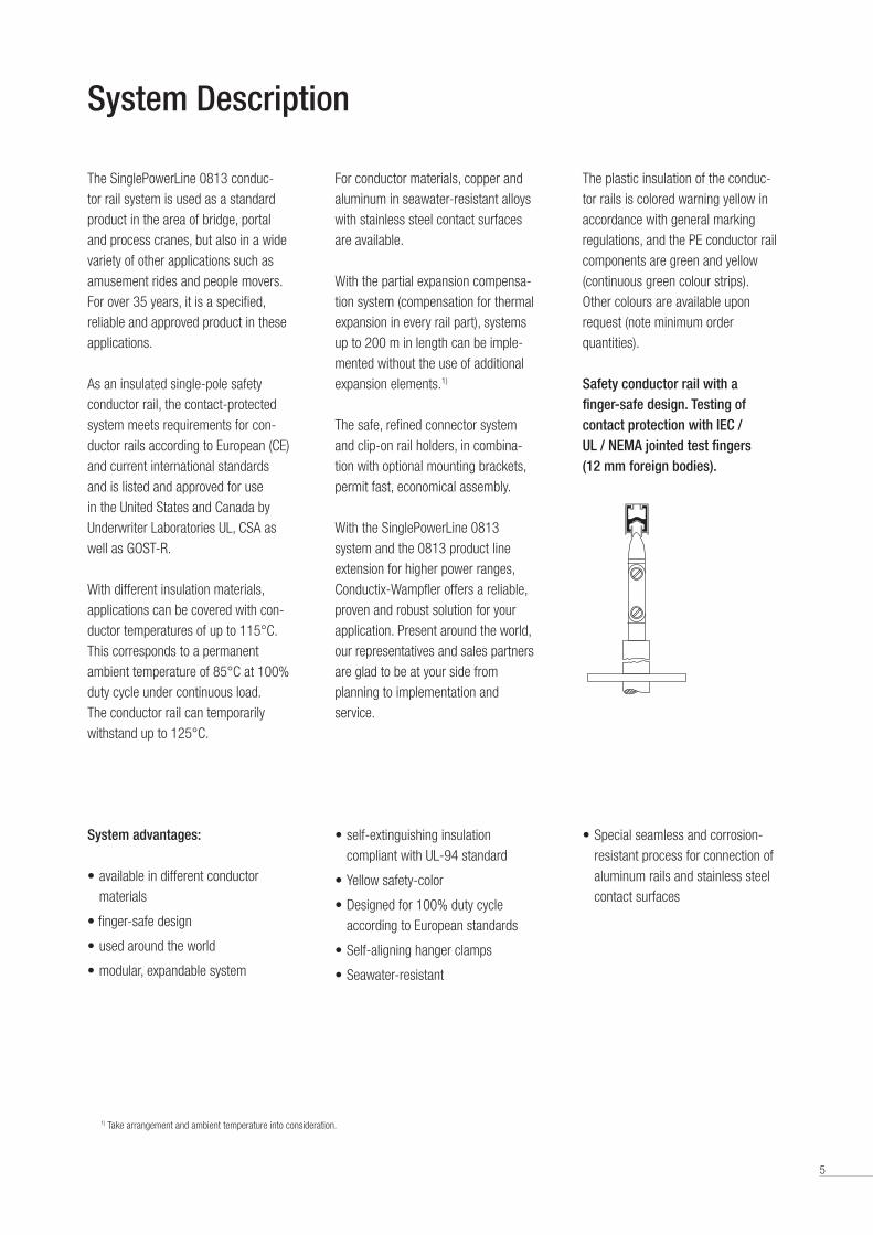
Safety conductor rail with a finger-safe design. Testing of contact protection with IEC / UL / NEMA jointed test fingers (12 mm foreign bodies).
• Special seamless and corrosion-resistant process for connection of aluminum rails and stainless steel contact surfaces
1) Take arrangement and ambient temperature into consideration .
6
Technical Data
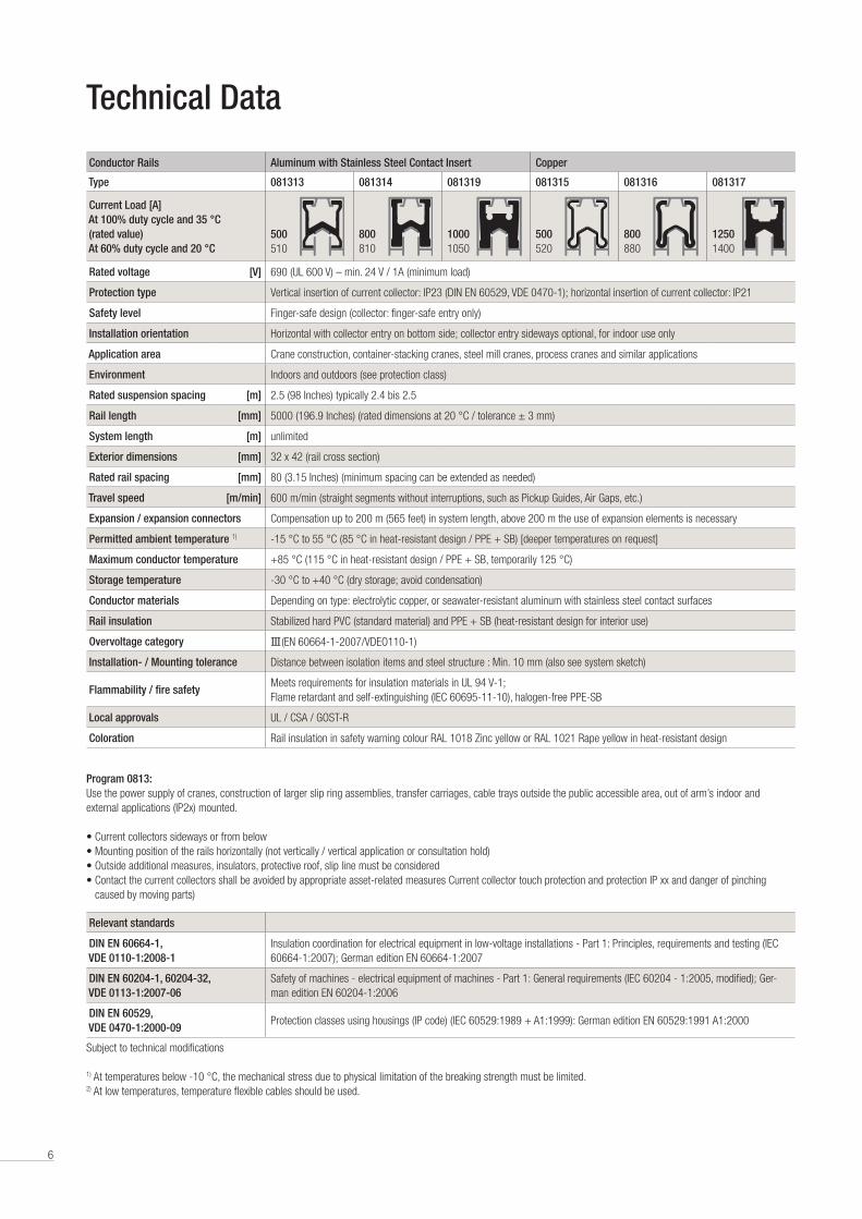
Conductor Rails Aluminum with Stainless Steel Contact Insert Copper
Type 081313 081314 081319 081315 081316 081317
Current Load [A] At 100% duty cycle and 35 °C (rated value) At 60% duty cycle and 20 °C
500510
800810
10001050
500520
800880
12501400
Rated voltage [V] 690 (UL 600 V) – min . 24 V / 1A (minimum load)
Protection type Vertical insertion of current collector: IP23 (DIN EN 60529, VDE 0470-1); horizontal insertion of current collector: IP21
Safety level Finger-safe design (collector: finger-safe entry only)
Installation orientation Horizontal with collector entry on bottom side; collector entry sideways optional, for indoor use only
Application area Crane construction, container-stacking cranes, steel mill cranes, process cranes and similar applications
Environment Indoors and outdoors (see protection class)
Rated suspension spacing [m] 2 .5 (98 Inches) typically 2 .4 bis 2 .5
Rail length [mm] 5000 (196 .9 Inches) (rated dimensions at 20 °C / tolerance ± 3 mm)
System length [m] unlimited
Exterior dimensions [mm] 32 x 42 (rail cross section)
Rated rail spacing [mm] 80 (3 .15 Inches) (minimum spacing can be extended as needed)
Travel speed [m/min] 600 m/min (straight segments without interruptions, such as Pickup Guides, Air Gaps, etc .)
Expansion / expansion connectors Compensation up to 200 m (565 feet) in system length, above 200 m the use of expansion elements is necessary
Permitted ambient temperature 1) -15 °C to 55 °C (85 °C in heat-resistant design / PPE + SB) [deeper temperatures on request]
Maximum conductor temperature +85 °C (115 °C in heat-resistant design / PPE + SB, temporarily 125 °C)
Storage temperature -30 °C to +40 °C (dry storage; avoid condensation)
Conductor materials Depending on type: electrolytic copper, or seawater-resistant aluminum with stainless steel contact surfaces
Rail insulation Stabilized hard PVC (standard material) and PPE + SB (heat-resistant design for interior use)
Overvoltage category III (EN 60664-1-2007/VDEO110-1)
Installation- / Mounting tolerance Distance between isolation items and steel structure : Min . 10 mm (also see system sketch)
Flammability / fire safetyMeets requirements for insulation materials in UL 94 V-1; Flame retardant and self-extinguishing (IEC 60695-11-10), halogen-free PPE-SB
Local approvals UL / CSA / GOST-R
Coloration Rail insulation in safety warning colour RAL 1018 Zinc yellow or RAL 1021 Rape yellow in heat-resistant design
Program 0813:Use the power supply of cranes, construction of larger slip ring assemblies, transfer carriages, cable trays outside the public accessible area, out of arm’s indoor and external applications (IP2x) mounted .
• Current collectors sideways or from below• Mounting position of the rails horizontally (not vertically / vertical application or consultation hold)• Outside additional measures, insulators, protective roof, slip line must be considered • Contact the current collectors shall be avoided by appropriate asset-related measures Current collector touch protection and protection IP xx and danger of pinching caused by moving parts)
Relevant standards
DIN EN 60664-1, VDE 0110-1:2008-1
Insulation coordination for electrical equipment in low-voltage installations - Part 1: Principles, requirements and testing (IEC 60664-1:2007); German edition EN 60664-1:2007
DIN EN 60204-1, 60204-32, VDE 0113-1:2007-06
Safety of machines - electrical equipment of machines - Part 1: General requirements (IEC 60204 - 1:2005, modified); Ger-man edition EN 60204-1:2006
DIN EN 60529, VDE 0470-1:2000-09
Protection classes using housings (IP code) (IEC 60529:1989 + A1:1999): German edition EN 60529:1991 A1:2000
Subject to technical modifications
1) At temperatures below -10 °C, the mechanical stress due to physical limitation of the breaking strength must be limited .2) At low temperatures, temperature flexible cables should be used .

7
General Instructions
Application AreaThis product is intended for the supply of mobile consumers in the rated current range up to 1250 A and voltages up to 690 V / 1000 V . Target applications are hoist/crane systems, container stacking cranes, steel mill- or STS-cranes and similar ap-plications with one or more mobile units .
The insulation materials are resistant to many ingredients used in the industrial environment, depending on concentration and exposure time . All metal parts are available in copper or seawater-resistant aluminum depending on construction type, and should be evaluated in accordance with the general suitability of these basic materials .
Before using in critical environmental con-ditions such as galvanizing plants, pickling plants, compost works and locations with high concentrations of chemicals (e .g . solvents, aromatics, benzols, etc .), please contact us .
LayoutThere are several decisive factors in the selection and layout of conductor rails . One main characteristic is the current load that actually occurs (total current to be expected during operation – not to be confused with the installed power or the resulting maxi-mum current) and the resistance values of the system . Here we look at the longest segment between the power feed and the position of the consumer during start-up . The criterion in question is the resulting voltage drop . Depending on the conductor material and cross section, different losses can result for the same length and current . A conductor rail is properly dimensioned from the point of view of voltage drop when the drop lies within the permitted tolerance range, generally 2-5% and at most 10% including the connection feed cable .
Conductor rails are classified by their rated current . This corresponds to the maximum continuous current for the conductor rail and is based on the standard parameters of 35 °C ambient temperature and 100% duty cycle (according to IEC >_ 10 min ON) . If the duty cycle or ambient temperature is lower, higher currents can be transmit-ted . Further information about the layout
of conductor rails and corrections to rated current specifications is listed starting on page 22 .
Electrical SafetyInsulated SinglePowerLine 0813 conductor rails are designed according to applicable international standards and guidelines, meet today's requirements for the safety of a conductor rail and have contact protection compliant with DIN EN 60529 (protection class IP 23) . They meet the general requirements for classification and evaluation defined in DIN EN 60204 part 32 - Electrical requirements for hoisting machines .
Conductor rails and rail components have a high level of safety . With contact protec-tion, direct contact between body parts and electrically conducting parts is prevented (finger protection with DIN VDE and EN /NEMA test fingers / 12 mm foreign bodies) . The current collectors are also designed finger-safe when engaged in the rails, but in areas where they leave the rails, such as intersections and switch points, they must be additionally protected using power switches, covers or distance . Installations with voltages over 25 V DC and 60 V AC in publically accessible areas must be secured by covers, installation away from accessible areas or other suitable means .
Installations in which the insulation characteristics may be reduced by con-ductive dust or moisture must be installed away from access by people and be marked as high-voltage electrical equipment with warning signs . In areas with high operating voltage (> 690 V) and installations in a highly contaminated envi-ronment with conductive dust or moisture, insulators must be used .
The single-pole system can be built with any number of poles and extended in a modular manner . Components for the protective conductor are marked in green or green/yellow and may not be used as phase components . Using installed parts and position coding, it is impossible to en-gage the PE current collector into a phase pole, or to mix phases . We recommend laying out the PE contact redundantly with two current collectors .
Mechanical SafetyPlease note that the layout of conductor rails and current collectors between fixed and moving system parts must maintain a safety spacing of at least 0 .5 m to avoid crushing risks, or other safety measures must be taken to prevent this risk .
In exposed installation situations, for exam-ple over traffic ways, please ask for details .
Use of Conductor RailsThe conductor rails of Program 0813 meet current standards and guidelines for the intended use of the components . For instal-lation into the final product, the specifica-tions valid for this product must be taken into consideration and you must proceed in accordance with the Machine Directive or with the guidelines valid for the place of installation .
Use outdoorsOutdoors, the conductor rail should be protected from environmental influences as much as possible . Use in high humidity and low temperature areas runs the risk of condensation, the formation of frost and ice build-up on the contact surfaces . In installation in this environment, the rails, in particular aluminum rails, must be equipped with an optional rail heater . Our sales department will be glad to assist you with the layout .
ApprovalsThe conductor rail product line meets the product parameters required for interna-tional use for these products and has been developed in accordance with the existing standards and guidelines in the EU and the important industrial markets . In addition to IEC/EN standard compliance, the product line also has local UL/CSA and GOST-R approvals .
8
System Structure
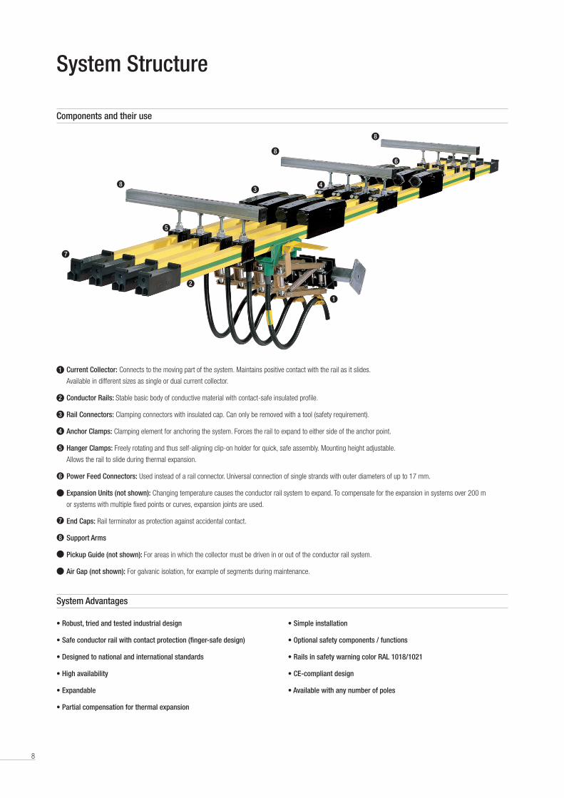
Components and their use
1
4
5
8
8
8
7
2
3
6
Current Collector: Connects to the moving part of the system . Maintains positive contact with the rail as it slides .
Available in different sizes as single or dual current collector .
Conductor Rails: Stable basic body of conductive material with contact-safe insulated profile .
Rail Connectors: Clamping connectors with insulated cap . Can only be removed with a tool (safety requirement) .
Anchor Clamps: Clamping element for anchoring the system . Forces the rail to expand to either side of the anchor point .
Hanger Clamps: Freely rotating and thus self-aligning clip-on holder for quick, safe assembly . Mounting height adjustable .
Allows the rail to slide during thermal expansion .
Power Feed Connectors: Used instead of a rail connector . Universal connection of single strands with outer diameters of up to 17 mm .
Expansion Units (not shown): Changing temperature causes the conductor rail system to expand . To compensate for the expansion in systems over 200 m
or systems with multiple fixed points or curves, expansion joints are used .
End Caps: Rail terminator as protection against accidental contact .
Support Arms
Pickup Guide (not shown): For areas in which the collector must be driven in or out of the conductor rail system .
Air Gap (not shown): For galvanic isolation, for example of segments during maintenance .
1
2
3
4
5
6
7
8
• Robust, tried and tested industrial design
• Safe conductor rail with contact protection (finger-safe design)
• Designed to national and international standards
• High availability
• Expandable
• Partial compensation for thermal expansion
• Simple installation
• Optional safety components / functions
• Rails in safety warning color RAL 1018/1021
• CE-compliant design
• Available with any number of poles
System Advantages
9
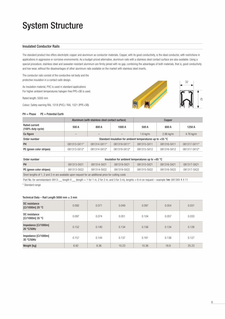
Insulated Conductor Rails
System Structure
The standard product line offers electrolytic copper and aluminum as conductor materials . Copper, with its good conductivity, is the ideal conductor, with restrictions in
applications in aggressive or corrosive environments . As a budget-priced alternative, aluminum rails with a stainless steel contact surface are also available . Using a
special procedure, stainless steel and seawater-resistant aluminum are firmly joined with no gap, combining the advantages of both materials, that is, good conductivity
and low wear, without the disadvantages of other aluminum rails available on the market with stainless steel inserts .
The conductor rails consist of the conductive rail body and the
protective insulation in a contact-safe design .
As insulation material, PVC is used in standard applications
For higher ambient temperatures halogen-free PPE+SB is used .
Rated length: 5000 mm
Colour: Safety warning RAL 1018 (PVC) / RAL 1021 (PPE+SB)
PH = Phase PE = Potential Earth
Aluminum (with stainless steel contact surface) Copper
Rated current (100% duty cycle)
500 A 800 A 1000 A 500 A 800 A 1250 A
Cu figure – – – 1 .6 kg/m 2 .86 kg/m 4 .76 kg/m
Order number Standard insulation for ambient temperatures up to +55 °C
PH 081313-5X11* 081314-5X11* 081319-5X11* 081315-5X11 081316-5X11 081317-5X11*
PE (green color stripes) 081313-5X12* 081314-5X12* 081319-5X12* 081315-5X12 081316-5X12 081317-5X12*
Order number Insulation for ambient temperatures up to +85 °C
PH 081313-5X21 081314-5X21 081319-5X21 081315-5X21 081316-5X21 081317-5X21
PE (green color stripes) 081313-5X22 081314-5X22 081319-5X22 081315-5X22 081316-5X22 081317-5X22
Short lengths of 1, 2 and 3 m are available upon request for an additional price for cutting costs
Part No . for semistandard: 0813-__-length X __ (length = 1 for 1 m, 2 for 2 m, and 3 for 3 m), lenghts > 6 m on request – example 1m: 0813XX-1 X 11
* Standard range
Technical Data – Rail Length 5000 mm ± 3 mm
DC resistance [Ω/1000m] 20 °C
0 .092 0 .071 0 .049 0 .097 0 .054 0 .031
DC resistance [Ω/1000m] 35 °C
0 .097 0 .074 0 .051 0 .104 0 .057 0 .033
Impedance [Ω/1000m] 20 °C/50Hz
0 .152 0 .140 0 .134 0 .156 0 .134 0 .126
Impedance [Ω/1000m] 35 °C/50Hz
0 .157 0 .144 0 .137 0 .161 0 .136 0 .127
Weight [kg] 6 .92 8 .36 10 .23 10 .36 16 .9 25 .23
32
42
10
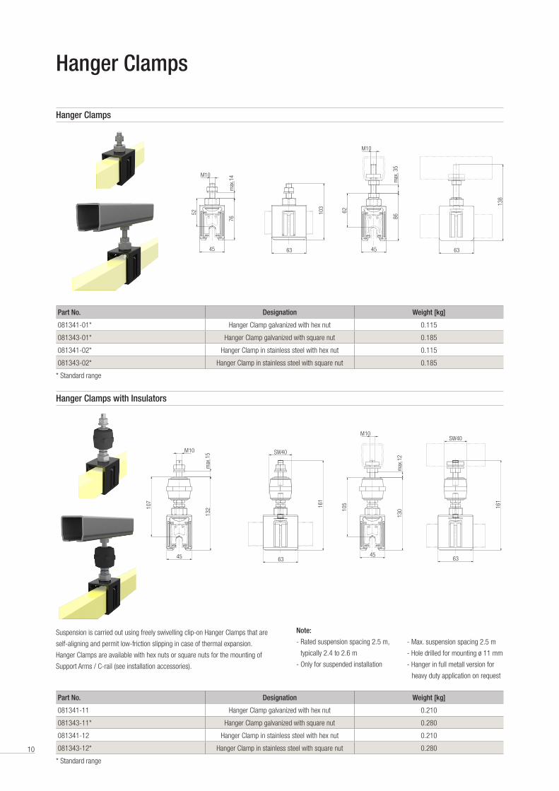
Hanger Clamps
Suspension is carried out using freely swivelling clip-on Hanger Clamps that are
self-aligning and permit low-friction slipping in case of thermal expansion .
Hanger Clamps are available with hex nuts or square nuts for the mounting of
Support Arms / C-rail (see installation accessories) .
Note:
- Rated suspension spacing 2 .5 m,
typically 2 .4 to 2 .6 m
- Only for suspended installation
- Max . suspension spacing 2 .5 m
- Hole drilled for mounting ø 11 mm
- Hanger in full metall version for
heavy duty application on request
Hanger Clamps
Hanger Clamps with Insulators
63
103
52
M10
max
.14
76
45
M10
45
107
132
max
.15
63
SW40
161
M10
45
62
86m
ax. 3
5
63
138
45
105
M10
130
max
.12
63
SW40
161
Part No. Designation Weight [kg]
081341-01* Hanger Clamp galvanized with hex nut 0 .115
081343-01* Hanger Clamp galvanized with square nut 0 .185
081341-02* Hanger Clamp in stainless steel with hex nut 0 .115
081343-02* Hanger Clamp in stainless steel with square nut 0 .185
* Standard range
Part No. Designation Weight [kg]
081341-11 Hanger Clamp galvanized with hex nut 0 .210
081343-11* Hanger Clamp galvanized with square nut 0 .280
081341-12 Hanger Clamp in stainless steel with hex nut 0 .210
081343-12* Hanger Clamp in stainless steel with square nut 0 .280
* Standard range
11
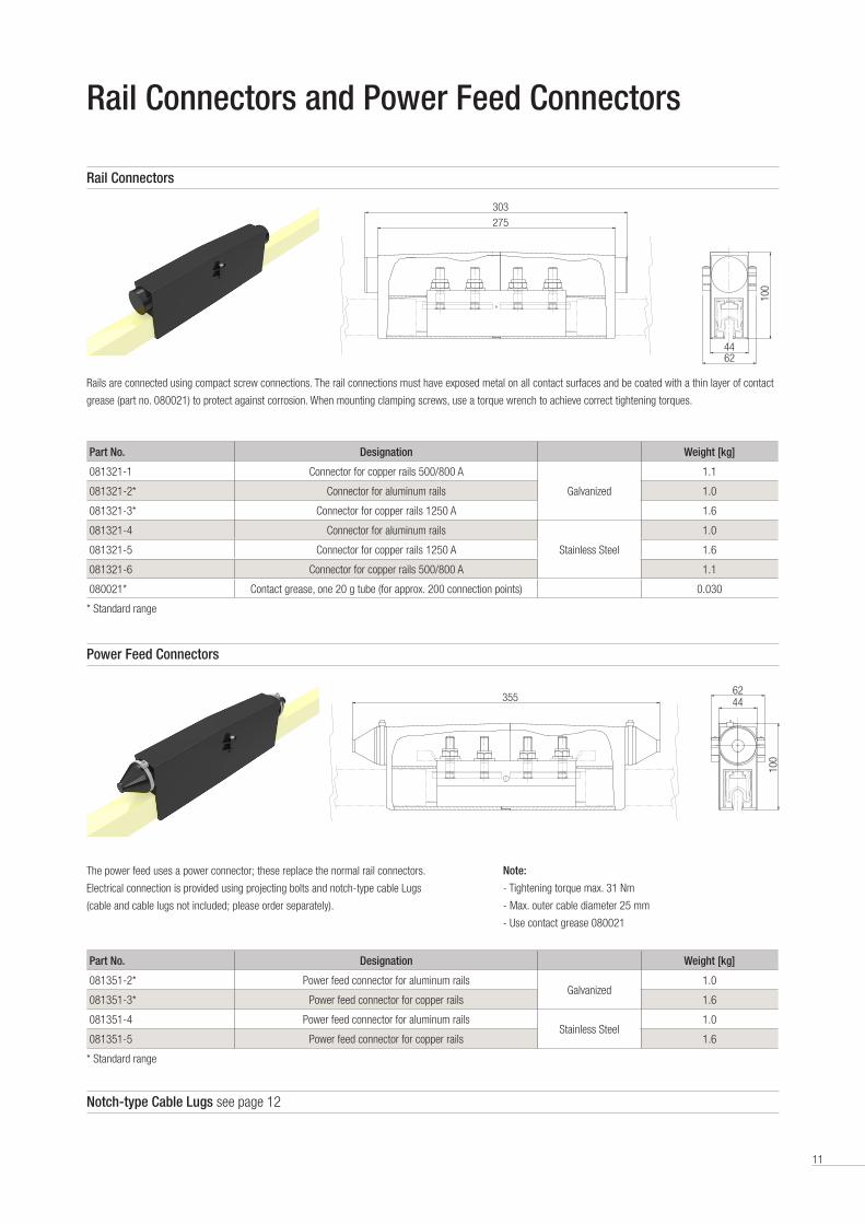
Rail Connectors and Power Feed Connectors
Part No. Designation Weight [kg]
081321-1 Connector for copper rails 500/800 A
Galvanized
1 .1
081321-2* Connector for aluminum rails 1 .0
081321-3* Connector for copper rails 1250 A 1 .6
081321-4 Connector for aluminum rails
Stainless Steel
1 .0
081321-5 Connector for copper rails 1250 A 1 .6
081321-6 Connector for copper rails 500/800 A 1 .1
080021* Contact grease, one 20 g tube (for approx . 200 connection points) 0 .030
* Standard range
Rail Connectors
Rails are connected using compact screw connections . The rail connections must have exposed metal on all contact surfaces and be coated with a thin layer of contact
grease (part no . 080021) to protect against corrosion . When mounting clamping screws, use a torque wrench to achieve correct tightening torques .
303
275
62
100
44
Power Feed Connectors
The power feed uses a power connector; these replace the normal rail connectors .
Electrical connection is provided using projecting bolts and notch-type cable Lugs
(cable and cable lugs not included; please order separately) .
Note:
- Tightening torque max . 31 Nm
- Max . outer cable diameter 25 mm
- Use contact grease 080021
Part No. Designation Weight [kg]
081351-2* Power feed connector for aluminum railsGalvanized
1 .0
081351-3* Power feed connector for copper rails 1 .6
081351-4 Power feed connector for aluminum railsStainless Steel
1 .0
081351-5 Power feed connector for copper rails 1 .6
* Standard range
355 4462
100
Notch-type Cable Lugs see page 12
12
Anchor Clamps
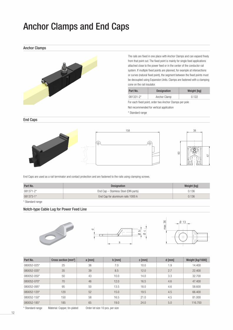
The rails are fixed in one place with Anchor Clamps and can expand freely
from that point out . The fixed point is mainly for single feed applications
attached close to the power feed or in the center of the conductor rail
system . If multiple fixed points are planned, for example at intersections
or curves (natural fixed point), the segment between the fixed points must
be decoupled using Expansion Units . Clamps are fastened with a clamping
cone on the rail insulator .
Part No. Designation Weight [kg]
081331-2* Anchor Clamp 0 .122
For each fixed point, order two Anchor Clamps per pole
Not recommended for vertical application
* Standard range
End Caps
End Caps are used as a rail terminator and contact protection and are fastened to the rails using clamping screws .
Part No. Designation Weight [kg]
081371-2* End Cap – Stainless Steel (DIN parts) 0 .136
081373-1* End Cap for aluminum rails 1000 A 0 .136
* Standard range
Anchor Clamps and End Caps
38
47
60
158
Notch-type Cable Lug for Power Feed Line
Part No. Cross section [mm2] a [mm] b [mm] c [mm] d [mm] Weight [kg/1000]
080052-025* 25 36 7 .0 10 .0 1 .9 14 .400
080052-035* 35 39 8 .5 12 .0 2 .7 22 .400
080052-050* 50 43 10 .0 14 .0 3 .3 32 .700
080052-070* 70 46 12 .0 16 .5 4 .6 47 .400
080052-095* 95 50 13 .5 18 .0 4 .6 58 .600
080052-120* 120 52 15 .0 19 .5 4 .5 66 .400
080052-150* 150 58 16 .5 21 .0 4 .5 81 .000
080052-185* 185 65 19 .0 24 .0 5 .0 116 .700
* Standard range Material: Copper, tin-plated Order lot size 10 pcs . per size
a
Øc
Øbd
Ø 13
max
. 36
a
Øc
Øbd
Ø 13
max
. 36
13
Air Gaps
Air Gaps
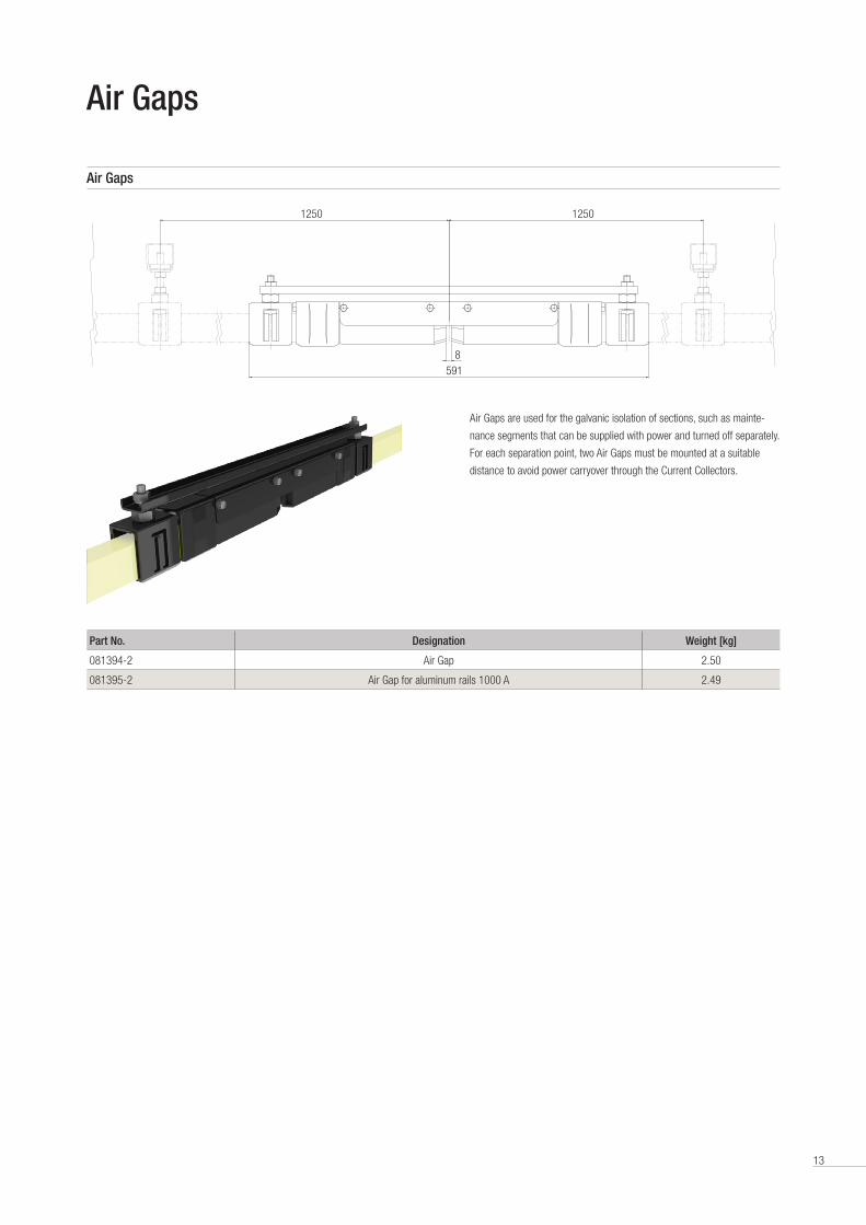
Part No. Designation Weight [kg]
081394-2 Air Gap 2 .50
081395-2 Air Gap for aluminum rails 1000 A 2 .49
1250 1250
8591
Air Gaps are used for the galvanic isolation of sections, such as mainte-
nance segments that can be supplied with power and turned off separately .
For each separation point, two Air Gaps must be mounted at a suitable
distance to avoid power carryover through the Current Collectors .
14
Expansion Units
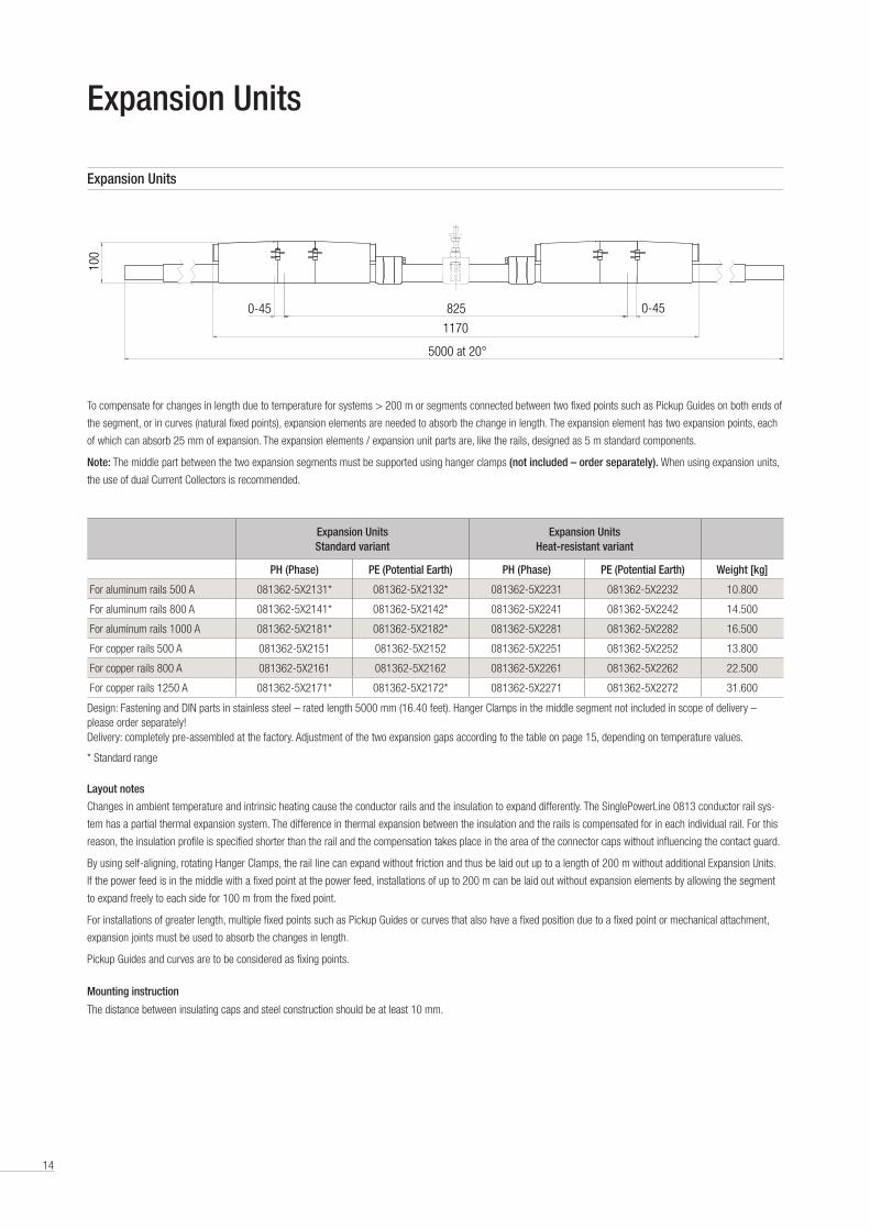
To compensate for changes in length due to temperature for systems > 200 m or segments connected between two fixed points such as Pickup Guides on both ends of
the segment, or in curves (natural fixed points), expansion elements are needed to absorb the change in length . The expansion element has two expansion points, each
of which can absorb 25 mm of expansion . The expansion elements / expansion unit parts are, like the rails, designed as 5 m standard components .
Note: The middle part between the two expansion segments must be supported using hanger clamps (not included – order separately). When using expansion units,
the use of dual Current Collectors is recommended .
Layout notes
Changes in ambient temperature and intrinsic heating cause the conductor rails and the insulation to expand differently . The SinglePowerLine 0813 conductor rail sys-
tem has a partial thermal expansion system . The difference in thermal expansion between the insulation and the rails is compensated for in each individual rail . For this
reason, the insulation profile is specified shorter than the rail and the compensation takes place in the area of the connector caps without influencing the contact guard .
By using self-aligning, rotating Hanger Clamps, the rail line can expand without friction and thus be laid out up to a length of 200 m without additional Expansion Units .
If the power feed is in the middle with a fixed point at the power feed, installations of up to 200 m can be laid out without expansion elements by allowing the segment
to expand freely to each side for 100 m from the fixed point .
For installations of greater length, multiple fixed points such as Pickup Guides or curves that also have a fixed position due to a fixed point or mechanical attachment,
expansion joints must be used to absorb the changes in length .
Pickup Guides and curves are to be considered as fixing points .
Mounting instruction
The distance between insulating caps and steel construction should be at least 10 mm .
Expansion Units Standard variant
Expansion Units Heat-resistant variant
PH (Phase) PE (Potential Earth) PH (Phase) PE (Potential Earth) Weight [kg]
For aluminum rails 500 A 081362-5X2131* 081362-5X2132* 081362-5X2231 081362-5X2232 10 .800
For aluminum rails 800 A 081362-5X2141* 081362-5X2142* 081362-5X2241 081362-5X2242 14 .500
For aluminum rails 1000 A 081362-5X2181* 081362-5X2182* 081362-5X2281 081362-5X2282 16 .500
For copper rails 500 A 081362-5X2151 081362-5X2152 081362-5X2251 081362-5X2252 13 .800
For copper rails 800 A 081362-5X2161 081362-5X2162 081362-5X2261 081362-5X2262 22 .500
For copper rails 1250 A 081362-5X2171* 081362-5X2172* 081362-5X2271 081362-5X2272 31 .600
Design: Fastening and DIN parts in stainless steel – rated length 5000 mm (16 .40 feet) . Hanger Clamps in the middle segment not included in scope of delivery – please order separately! Delivery: completely pre-assembled at the factory . Adjustment of the two expansion gaps according to the table on page 15, depending on temperature values .
* Standard range
Expansion Units
0-45 0-45825
5000 bei 20°
1170
100
5000 at 20°
15
Number of Expansion Units for systems over 200 m in length
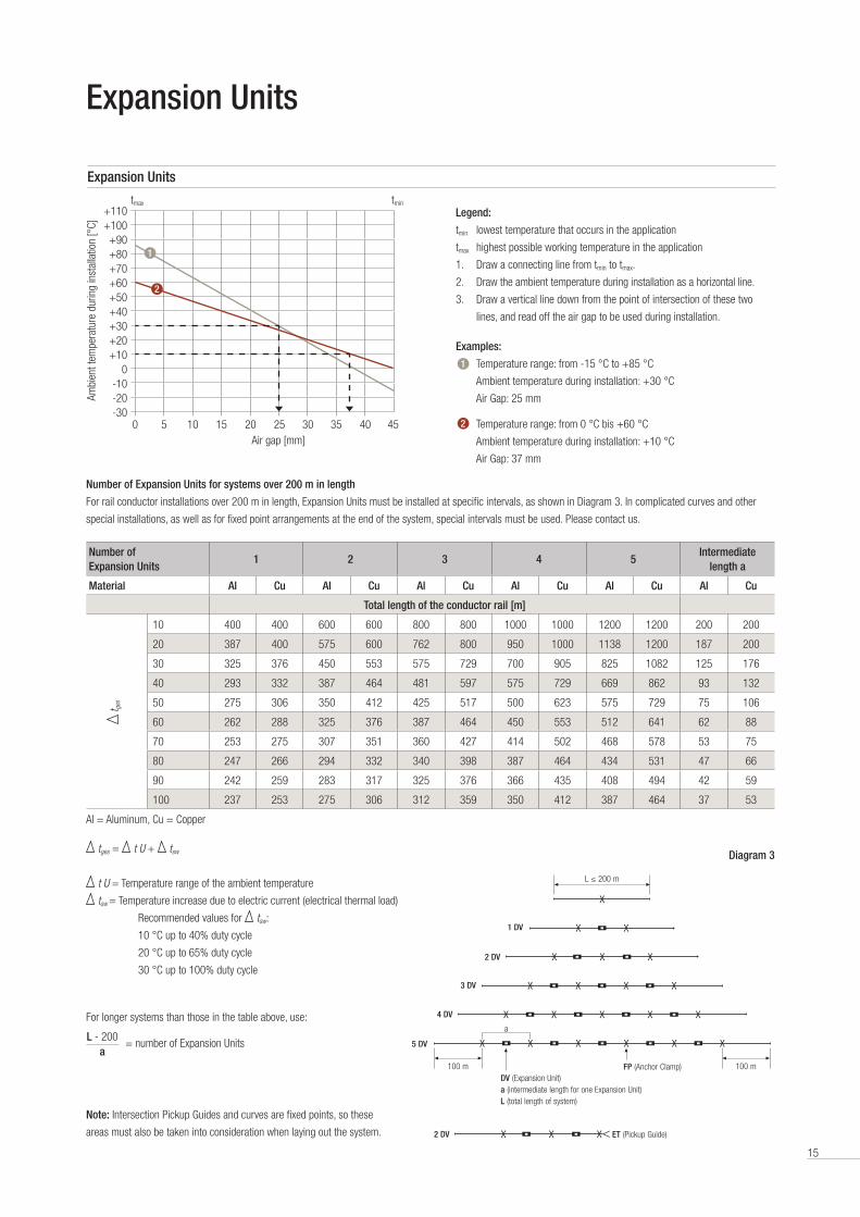
For rail conductor installations over 200 m in length, Expansion Units must be installed at specific intervals, as shown in Diagram 3 . In complicated curves and other
special installations, as well as for fixed point arrangements at the end of the system, special intervals must be used . Please contact us .
Legend:
tmin lowest temperature that occurs in the application
tmax highest possible working temperature in the application
1 . Draw a connecting line from tmin to tmax .
2 . Draw the ambient temperature during installation as a horizontal line .
3 . Draw a vertical line down from the point of intersection of these two
lines, and read off the air gap to be used during installation .
Examples:
Temperature range: from -15 °C to +85 °C
Ambient temperature during installation: +30 °C
Air Gap: 25 mm
Temperature range: from 0 °C bis +60 °C
Ambient temperature during installation: +10 °C
Air Gap: 37 mm
Expansion Units
Number of Expansion Units
1 2 3 4 5Intermediate
length a
Material Al Cu Al Cu Al Cu Al Cu Al Cu Al Cu
Total length of the conductor rail [m]
10 400 400 600 600 800 800 1000 1000 1200 1200 200 200
20 387 400 575 600 762 800 950 1000 1138 1200 187 200
30 325 376 450 553 575 729 700 905 825 1082 125 176
40 293 332 387 464 481 597 575 729 669 862 93 132
50 275 306 350 412 425 517 500 623 575 729 75 106
60 262 288 325 376 387 464 450 553 512 641 62 88
70 253 275 307 351 360 427 414 502 468 578 53 75
80 247 266 294 332 340 398 387 464 434 531 47 66
90 242 259 283 317 325 376 366 435 408 494 42 59
100 237 253 275 306 312 359 350 412 387 464 37 53
Al = Aluminum, Cu = Copper
-300 5 10 15 20 25 30 35 40 45
+10
+30
+50
+70
+90
+20
+40
+60
+80
+100+110
-20-10
0
Air gap [mm]
Ambi
ent t
empe
ratu
re d
urin
g in
stal
latio
n [°
C]
tmintmax
L ≤ 200 m
DV (Expansion Unit)a (intermediate length for one Expansion Unit)L (total length of system)
FP (Anchor Clamp)100 m
a
100 m
1 DV
2 DV
3 DV
4 DV
5 DV
t ges
Expansion Units
Diagram 3
1
1
2
2
tges = t U + tsw
t U = Temperature range of the ambient temperature
tsw = Temperature increase due to electric current (electrical thermal load)
Recommended values for tsw:
10 °C up to 40% duty cycle
20 °C up to 65% duty cycle
30 °C up to 100% duty cycle
For longer systems than those in the table above, use:
= number of Expansion UnitsL - 200
a
Note: Intersection Pickup Guides and curves are fixed points, so these
areas must also be taken into consideration when laying out the system . 2 DV ET (Pickup Guide)

16
Pickup Guides for Intersections
For areas in which the collector must be driven in or out of the conductor rail system, Pickup Guides are used in combination with Current Collectors provided for this
purpose . The speed for Pickup Guide entry must not exceed 80 m/min and that Pickup Guides must be considered wearing parts .
Installation tolerances must be taken into consideration . Simultaneous alignment gaps with maximum tolerances in the X and Y directions are not permitted .
- The Pickup Guide centers the Current Collector with a maximum lateral
and vertical alignment tolerance of ±25 mm .
- Settings of less than ±10 mm are recommended .
- In installations with Pickup Guides, a corresponding number of Current Collectors
must be available, and mounted in intervals that ensure that just the necessary
number of Current Collectors needed for momentary power requirements are in use .
The user must ensure that the Current Collectors between the Pickup Guides
are disconnected from power or are protected against accidental contact.
Installation note
The middle distance between two conductors is 80 mm . This is reduced to 65 mm using the last Hanger Clamp before the Pickup Guide in order to ensure that the
Current Collector enters the Pickup Guide precisely . The Pickup Guide is delivered complete with End Caps . The End Caps are pushed onto the rails with a soft-head
hammer until they hit the end stops . The clamping screws are then tightened firmly .
Please note also the instructions for mounting the PE Current Collector for installations with Pickup Guides .
Hanger Clamp spacing for installations with Pickup Guides
115 58
615490
109,
5
65 65
0-10M10
20
a
275
b
109.
5
Dimensions [mm] Number of poles
1 2 3 4 5
a 200 265 330 395 460
b 105 170 235 300 365
Part No. Type of fastening elements: stainless steel Weight [kg]
081382-12 1-pole Pickup Guide 1 .86
081382-22 2-pole Pickup Guide 2 .63
081382-32 3-pole Pickup Guide 3 .40
081382-42 4-pole Pickup Guide 4 .17
081382-52 5-pole Pickup Guide 4 .94
081383-12
for A
lum
inum
100
0 A 1-pole Pickup Guide 1 .86
081383-22 2-pole Pickup Guide 2 .63
081383-32 3-pole Pickup Guide 3 .40
081383-42 4-pole Pickup Guide 4 .17
081383-52 5-pole Pickup Guide 4 .94
560 1700 1700 2500 2500 2500 2500275
5865
65
8080
17
18
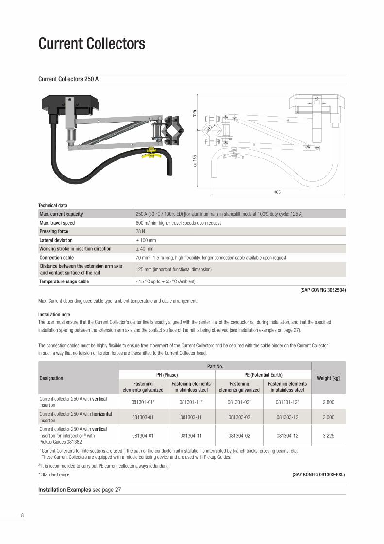
Technical data
Max. current capacity 250 A (30 °C / 100% ED) [for aluminum rails in standstill mode at 100% duty cycle: 125 A]
Max. travel speed 600 m/min; higher travel speeds upon request
Pressing force 28 N
Lateral deviation ± 100 mm
Working stroke in insertion direction ± 40 mm
Connection cable 70 mm2, 1 .5 m long, high-flexibility; longer connection cable available upon request
Distance between the extension arm axis and contact surface of the rail
125 mm (important functional dimension)
Temperature range cable - 15 °C up to + 55 °C (Ambient)
(SAP CONFIG 3052504)
Max . Current depending used cable type, ambient temperature and cable arrangement .
Current Collectors
Installation note
The user must ensure that the Current Collector's center line is exactly aligned with the center line of the conductor rail during installation, and that the specified
installation spacing between the extension arm axis and the contact surface of the rail is being observed (see installation examples on page 27) .
The connection cables must be highly flexible to ensure free movement of the Current Collectors and be secured with the cable binder on the Current Collector
in such a way that no tension or torsion forces are transmitted to the Current Collector head .
Current Collectors 250 A
Installation Examples see page 27
ca.1
8512
5465
40
Designation
Part No.
Weight [kg]PH (Phase) PE (Potential Earth)
Fastening elements galvanized
Fastening elements in stainless steel
Fastening elements galvanized
Fastening elements in stainless steel
Current collector 250 A with vertical insertion
081301-01* 081301-11* 081301-02* 081301-12* 2 .800
Current collector 250 A with horizontal insertion
081303-01 081303-11 081303-02 081303-12 3 .000
Current collector 250 A with vertical insertion for intersection1) with Pickup Guides 081382
081304-01 081304-11 081304-02 081304-12 3 .225
1) Current Collectors for intersections are used if the path of the conductor rail installation is interrupted by branch tracks, crossing beams, etc . These Current Collectors are equipped with a middle centering device and are used with Pickup Guides .
2) It is recommended to carry out PE current collector always redundant .
* Standard range (SAP KONFIG 08130X-PXL)
19
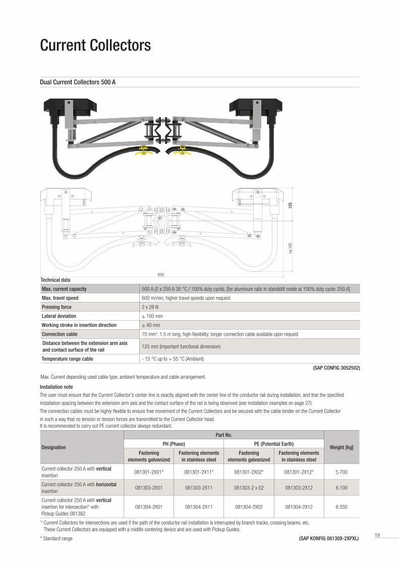
Technical data
Max. current capacity 500 A (2 x 250 A 30 °C / 100% duty cycle), [for aluminum rails in standstill mode at 100% duty cycle: 250 A]
Max. travel speed 600 m/min; higher travel speeds upon request
Pressing force 2 x 28 N
Lateral deviation ± 100 mm
Working stroke in insertion direction ± 40 mm
Connection cable 70 mm2, 1 .5 m long, high-flexibility; longer connection cable available upon request
Distance between the extension arm axis and contact surface of the rail
125 mm (important functional dimension)
Temperature range cable - 15 °C up to + 55 °C (Ambient)
(SAP CONFIG 3052502)
Max . Current depending used cable type, ambient temperature and cable arrangement .
Current Collectors
Installation note
The user must ensure that the Current Collector's center line is exactly aligned with the center line of the conductor rail during installation, and that the specified
installation spacing between the extension arm axis and the contact surface of the rail is being observed (see installation examples on page 27) .
The connection cables must be highly flexible to ensure free movement of the Current Collectors and be secured with the cable binder on the Current Collector
in such a way that no tension or torsion forces are transmitted to the Current Collector head .It is recommended to carry out PE current collector always redundant .
Dual Current Collectors 500 A
Designation
Part No.
Weight [kg]PH (Phase) PE (Potential Earth)
Fastening elements galvanized
Fastening elements in stainless steel
Fastening elements galvanized
Fastening elements in stainless steel
Current collector 250 A with vertical insertion
081301-2X01* 081301-2X11* 081301-2X02* 081301-2X12* 5 .700
Current collector 250 A with horizontal insertion
081303-2X01 081303-2X11 081303-2 x 02 081303-2X12 6 .100
Current collector 250 A with vertical insertion for intersection1) with Pickup Guides 081382
081304-2X01 081304-2X11 081304-2X02 081304-2X12 6 .550
1) Current Collectors for intersections are used if the path of the conductor rail installation is interrupted by branch tracks, crossing beams, etc . These Current Collectors are equipped with a middle centering device and are used with Pickup Guides .
* Standard range (SAP KONFIG 08130X-2XPXL)
ca.1
85
40
125
930
20
Current Collectors – Installation Instructions
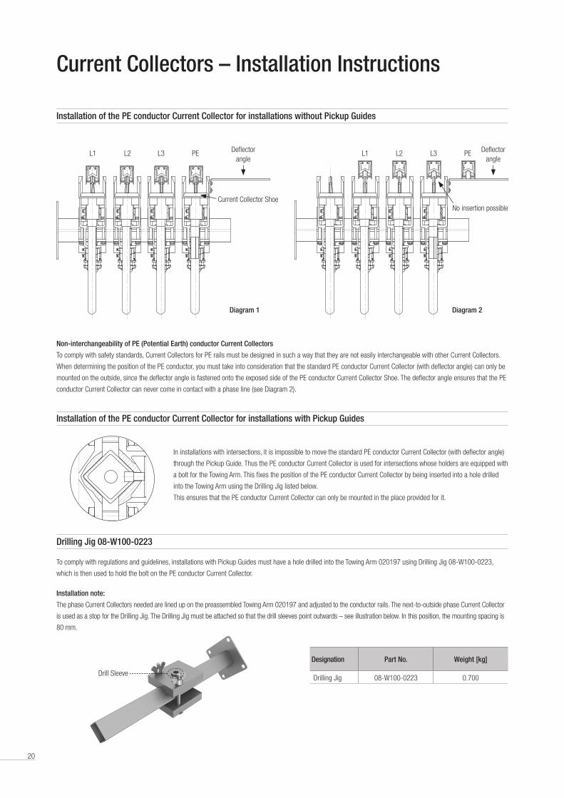
Installation of the PE conductor Current Collector for installations without Pickup Guides
Non-interchangeability of PE (Potential Earth) conductor Current Collectors
To comply with safety standards, Current Collectors for PE rails must be designed in such a way that they are not easily interchangeable with other Current Collectors .
When determining the position of the PE conductor, you must take into consideration that the standard PE conductor Current Collector (with deflector angle) can only be
mounted on the outside, since the deflector angle is fastened onto the exposed side of the PE conductor Current Collector Shoe . The deflector angle ensures that the PE
conductor Current Collector can never come in contact with a phase line (see Diagram 2) .
To comply with regulations and guidelines, installations with Pickup Guides must have a hole drilled into the Towing Arm 020197 using Drilling Jig 08-W100-0223,
which is then used to hold the bolt on the PE conductor Current Collector .
Installation note:
The phase Current Collectors needed are lined up on the preassembled Towing Arm 020197 and adjusted to the conductor rails . The next-to-outside phase Current Collector
is used as a stop for the Drilling Jig . The Drilling Jig must be attached so that the drill sleeves point outwards – see illustration below . In this position, the mounting spacing is
80 mm .
Designation Part No. Weight [kg]
Drilling Jig 08-W100-0223 0 .700
L1 L2 L3 PEPEL3L2L1L1 L1L2 L2L3 L3PE PE Deflector
angleDeflector
angle
Diagram 1 Diagram 2
Current Collector ShoeNo insertion possible
Installation of the PE conductor Current Collector for installations with Pickup Guides
Drilling Jig 08-W100-0223
In installations with intersections, it is impossible to move the standard PE conductor Current Collector (with deflector angle)
through the Pickup Guide . Thus the PE conductor Current Collector is used for intersections whose holders are equipped with
a bolt for the Towing Arm . This fixes the position of the PE conductor Current Collector by being inserted into a hole drilled
into the Towing Arm using the Drilling Jig listed below .
This ensures that the PE conductor Current Collector can only be mounted in the place provided for it .
Drill Sleeve
21

22
Dimensioning and Layout of Conductor Rail System
The dimensioning and layout of a conductor rail system is done as follows:
A: Determine the load current
B: Select the rail type
C: Check the voltage drop for the selected rail type
D: Check of ambient conditions
E: Select accessories and Current Collectors
A. Determining the load current (total rated current /NG)
To determine the total expected load current, individual currents of the highest draw consumers that can operate simultaneously are added up . If the entire installed
power is summed, the rail capacity will be over-specified . To avoid overdimensioning, the individual currents are evaluated for simultaneity . To optimizes the system,
it is always wise to consider individual consumers that cannot be operated simultaneously (e .g . a crane's slewing gear can only be operated when the crane trolley is
stopped), and then only the consumer (the slewing gear or the trolley) with the higher current consumption is used .
If multiple units are installed on a single track, for example three cranes on one crane track, the probability of simultaneous operation in the same load should be
used to calculate the current . In practice, the following simple table has proved useful in calculating the total rated current /NG for multiple consumers:
B. Rail current capacity depends on duty cycle and ambient temperature
The specified rated currents for the conductor rail are based on the definitions in European standards and are relative to an ambient temperature of 35 °C and a
duty cycle (DC) of 100% . If the duty cycle is shorter, such as might be the case for a crane with finite movement, the rail can conduct higher current than the rated
current .
Adjusting the rail rated current for shorter duty cycles
The load current of the conductor rail can be increased for shorter
duty cycles .
Note: When comparing the rated currents of rails from different
manufacturers, always take into consideration the reference
ambient temperature and the duty cycle!
Consumptions with 100% duty cycle such as lighting,
air conditioning or magnetic grippers must be taken
into consideration .
100% DC = t ≥10 min . (according to EN standards)1250 A Copper rails
1000 A Aluminum rails
800 A Copper rails800 A Aluminum rails
500 A Copper rails500 A Aluminum rails
Number of cranes
I N of the most powerful motor of all the
cranes I N*
I N of the second most powerful motor of all the
cranes I N*
I N of the third most powerful motor of all the
cranesI N*
I N of the fourth most powerful motor of all the
cranesI N*
1 × ×
2 × × ×
3 × × ×
4 × × × ×
5 × × × ×
According to work with 2 cranes × × × ×
* = For dual drives, use 2 · I N
[A]
% DC (duty cycle)
00 100908070605040302010
250
500
750
1000
1250
1500
1750
2000
2250
2500
2750
3000
23
Dimensioning and Layout
C. Calculating the voltage drop
After selecting the rail type based on the calculated total current depending on duty cycle and ambient temperature, the voltage drop must be checked . The calcu-
lated voltage drop must be under the value specified by the customer . Typical values here are 2-5%, or 10% in exceptional cases . If the voltage drop is too high, the
voltage might be too low to all the drives to start .
The following formulas are used for the calculation:
Note: IG here is the portion of the load current “drawn” during start-up .
This consists of the basic load, like lighting and air conditioners, and the start-up currents of the drives IA .
For start-up current, the following applies: Three-phase asynchronous drive in direct start IA = IN x 5 to 6 (up to max . 21 kW permitted) IG = total current
Slip ring rotor motor IA = IN x 3 to 5 IA = Total current con- sumption when starting
Frequency converter IA = IN x 1 .4 to 1 .8
The length l is the distance between the power feed and end position of the conductor rail segment on which the consumer is located when starting .
If the average ambient temperature is significantly over 35 °C, the voltage drop must be calculated using the following formulas:
The value f V is based on the working temperature and the conductor rail selected and should be taken from the table “Correction factors for the voltage drop U for different ambient temperatures” on page 24 .
If the ambient temperatures differ from the standard value of 35 °C, the loads must be adjusted . At lower temperatures, the heat release (convection) is better and the rail
can handle higher current loads . At higher temperatures, the release of thermal energy to the surrounding air is slower and the load must therefore be reduced .
The corresponding values f A are taken from the following table:
ISCHL G zul = ISCHL G zul 35 °C · f A ISCHL = rated current of the conductor rail for the specific ambient temperature
Ambient temperature 35 °C 40 °C 45 °C 50 °C 55 °C 60 °C 65 °C 70 °C 75 °C 80 °C 85 °C
Standard insulationAluminum rails
f A 1 .0 0 .92 0 .81 0 .76 0 .68
Copper rails 1 .0 0 .93 0 .87 0 .82 0 .78
Heat-resistant insulation
Aluminum railsf A
1 .0 0 .92 0 .81 0 .76 0 .68 0 .63 0 .59
Copper rails 1 .0 0 .93 0 .87 0 .82 0 .78 0 .74 0 .72
For direct current U 35 °C = 2 · I · IG · R [V] U 35 °C = voltage drop at 35 °C [V]
IG = total current [A]
For alternating current U 35 °C = 2 · I · IG · Z [V]R = resistance of the conductor rail [Ω/m]
Z = impedance of the conductor rail [Ω/m]
For three-phase power U 35 °C = √3 · I · IG · Z [V]I = feed length [m]
L = conductor rail length [m]
To calculate the value f V , the working temperature must first be calculated .
AT = UT + SW = UT + 30 [°C]
U = ——— [V] U 35 °C
f V
U % = ——— · 100 [%] U
UN
1) see feed variants
1)
U % = voltage drop at ambient temperature over 35 °C [%]
f V = reduction factor
U = voltage drop at higher ambient temperature than 35 °C [V]
UN = rated voltage [V]
AT = working temperature [°C]
UT = ambient temperature [°C]
SW = temperature increase due to current heating [°C] (use a constant +30 °C)

24
Dimensioning and Layout
If the voltage drop is too high, then either the number of power feeds must be increased or a larger conductor rail must be selected . Additional power feeds are usually a better technical and commercial alternative than larger conductor rails or costly copper rails .
Working temperature: permanent rail temperature occurring at rated current (ambient temperature + electrical thermal heating)
Max . working temperature: short-term (t < 30 sec) 125 °C (in heat-resistant variant)
Possible power feed locations: The power feed arrangement must be appropriate for the specific case, since the voltage drop is calculated with the feed length "l"
that falls between the power feed and the end of the conductor rail . The following power feed options are normally used:
Ambient temperature 35 °C 40 °C 45 °C 50 °C 55 °C 60 °C 65 °C 70 °C 75 °C 80 °C 85 °C
Working temperature / conductor temperature 65 °C 70 °C 75 °C 80 °C 85 °C 90 °C 95 °C 100 °C 105 °C 110 °C 115 °C
Standard insulation
Aluminum rails 500 A
f V
0 .965 0 .960 0 .954 0 .948 0 .943
Aluminum rails 800 A 0 .976 0 .972 0 .968 0 .964 0 .960
Aluminum rails 1000 A 0 .983 0 .980 0 .977 0 .974 0 .971
Copper rails 500 A 0 .959 0 .952 0 .945 0 .938 0 .932
Copper rails 800 A 0 .983 0 .980 0 .977 0 .974 0 .971
Copper rails 1250 A 0 .993 0 .992 0 .991 0 .990 0 .989
Heat-resistant insulation
Aluminum rails 500 A
f V
0 .943 0 .937 0 .932 0 .926 0 .920 0 .915 0 .909
Aluminum rails 800 A 0 .960 0 .956 0 .952 0 .948 0 .944 0 .940 0 .936
Aluminum rails 1000 A 0 .971 0 .968 0 .965 0 .962 0 .959 0 .956 0 .953
Copper rails 500 A 0 .932 0 .925 0 .919 0 .912 0 .905 0 .899 0 .893
Copper rails 800 A 0 .971 0 .968 0 .965 0 .961 0 .958 0 .955 0 .952
Copper rails 1250 A 0 .989 0 .987 0 .986 0 .985 0 .984 0 .982 0 .981
Correction factors for the voltage drop U at different ambient temperatures
I = L With an end power feed
I = L/2 With a middle power feed
I = L/4 For power feeds at both ends
I = L/6 For two power feeds each L/6
from the ends
I = L/10 For a power feed in the middle
and L/10 from each end
I = L/14 For four power feed points
L = length of the conductor rail [m]
Middle power feed
I = L/2L
L/10 power feed
I = L/10I = L/2
L
I = L/10
L/14 power feed
I = L/14I = L 5/14 I = L 9/14
L
I = L/14
L/6 power feed
I = L/6 I = L/6L
Power feed on both sides
I = L/4
I = L
End power feed
25
System Layoutca.360
≥ 250
1750
1750
2500
2500
2500
2500
2500
≥ 250
5000
5000
5000
125
465
930
ca.180
M10
ca.75M
10
ca.115
ca.135
M10
ca.145
M10
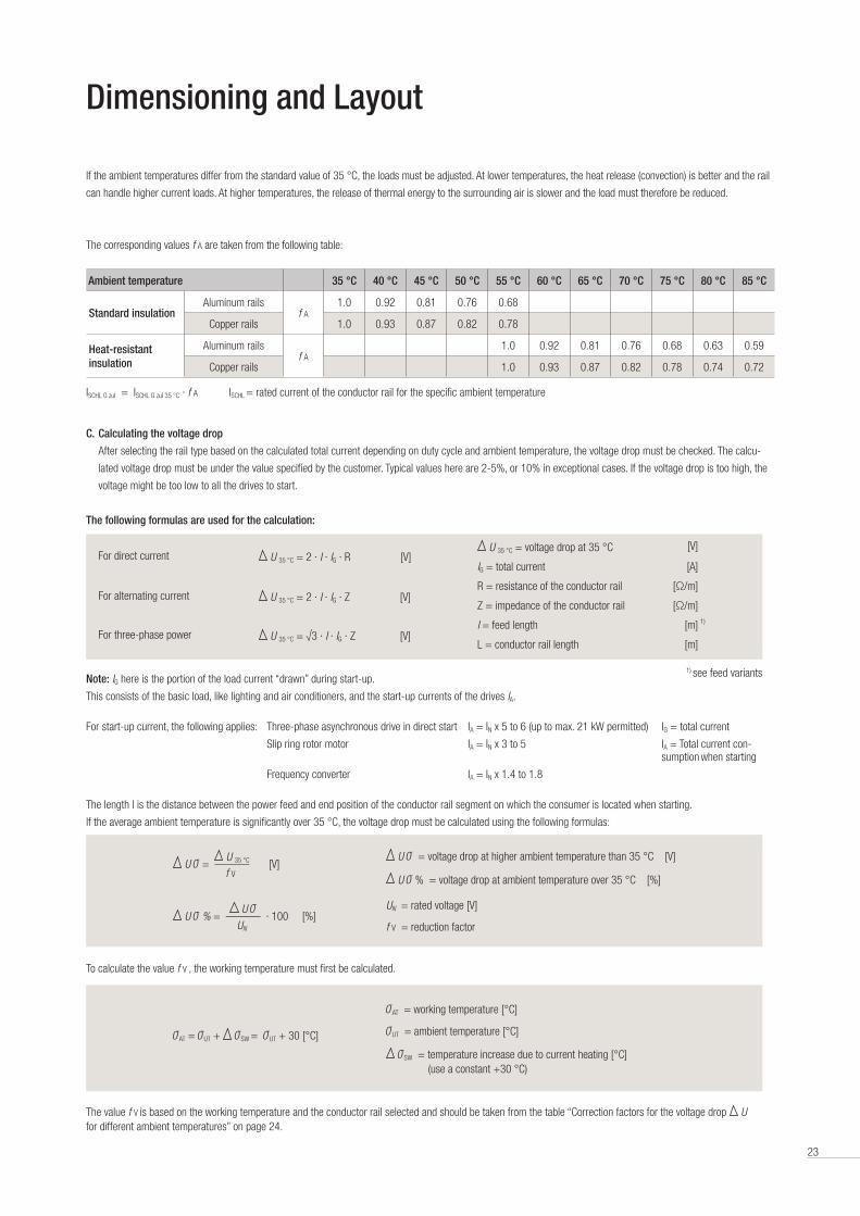
Note: Used outdoors, the conductor rail system must be protected
from direct weather exposure as much as possible, for example
by installing it under a beam and providing covering the Current
Collector (to protect it from snow and ice) . Outdoors, insertion of
the Current Collector from below is generally preferable to lateral
insertion . Also, the use of insulated holders is recommended for
outdoor installations . If there is any risk of formation of frost or ice,
specify heating conductors in the rail to de-ice the rail and prevent
rail damage due to sparking effects on frozen rails (Aluminum rails) .
Distance between insulation elements and steel structure min . 10 mm .
ø ≤
11
mm
26
System Layout
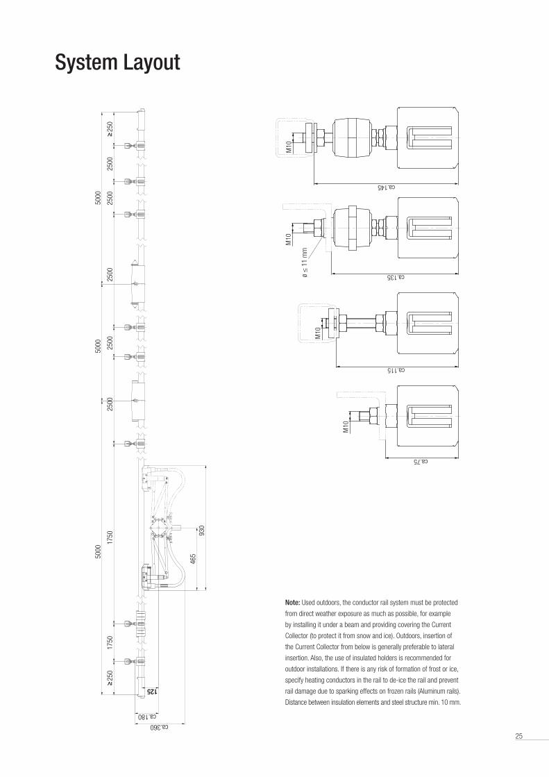
Example material overview / example order
Here is a typical crane conductor rail system that is 57 m in total length, with 4 poles, 800 A, with all accessories, Current Collectors and Support Arms .
The required Bill of Materials is listed below . The order quantity should be increased by an assembly reserve for the parts marked with an (x) .
Installation note
Regarding the first and the last conductor rail a support distance of 1750 and 250 mm from the beginning resp . the end of the rail is to be provided . Apart from that the
support spacing is 2 .5 m . The earth collector should always be installed on the outside . The centre distance between two conductors can be taken from the table below .
Note:
To avoid strand breakage due to external force on the Current Collector, the connection cable should be fine-stranded and highly flexible . The transition to the customer-
provided fixed cabling should be directly behind the Current Collector in a terminal box provided by the customer . Long connection cables to Current Collectors should
be avoided to reduce maintenance problems .
Distance between centers of two conductor rails
Standard current collector arrangement
Offset Current Collector arrangement
Current collector arrangement for installations with
multi-poled Pickup Guides*
Minimum distance a [mm] 80 70 80
* See mounting instructions for Pickup Guides .
Part Description Part No. Quantity Needed
Conductor Rail “Phase” 5 m long 081314-5X11* 33
Conductor Rail “Phase” 2 m long 081314*-2X11* 3
Conductor Rail “PE” 5 m long 081314-5X12* 11
Conductor Rail “PE” 2 m long 081314-2X12* 1
Hanger Clamp (x) 081343-01 96
Anchor Clamp 081331-1 8
Rail Connector (x) 081321-2 40
Power Feed 081351-2 4
Notch-type Cable Lug 95 mm2 (x) 080052-95 8
End Cap (x) 081371 8
Current Collector “Phase” 081301-2X1 3
Current Collector “PE” 081301-2X2 1
Extension Arm 020197-630 1
Support Arm 020186-500 24
Girder Clip 020286 24
Mounting Comb 081046 1
Conductix-Wampfler Contact Grease (x) 080021 1
Copper Graphite Shoe (replacement part) (x) 081003-11 4
Layout Schematic and Component Overview
Example: 5 m railmax . 200 m without Expansion Unit
max . 100 m
250 1750 1750 1250 1250 2500 1250
5000 5000
Rail length Rail length Rail length
5000
1250 1250 1750175012501250 250
max . 100 m
End Center
Hanger Clamp Hanger Clamp with Fixed Points End CapRail Connector Power feed
a a a
L1 L2 L3 PE

27
Layout Examples
For installations without transfer points the current collectors for vertical and horizontal operation can be stag gered .
This way the centre distance between two conductor rails is reduced by 10 mm .
Installation note
Please note that the centre line of the current collector is mounted to the centre line of the conductor rail . The distance between towing arm and conductor rail must be
set according to the dimension indicated in above table and sketches .
Standard Current Collector Layout
Offset Current Collector Arrangement
125
a a a
177,
517
7.5
Vertical and horizontal
insertion of Current Collectors
Distance between centers of two conductor rails
Standard current collector arrangement
Offset Current Collector arrangement
Current collector arrangement for installations with
multi-poled Pickup Guides*
Minimum distance a [mm] 80 70 80
* See mounting instructions for Pickup Guides .
Horizontal installation of conductor rails /
Vertical insertion of Current Collectors
Lateral installation of conductor rails /
Horizontal insertion of Current Collectors
28
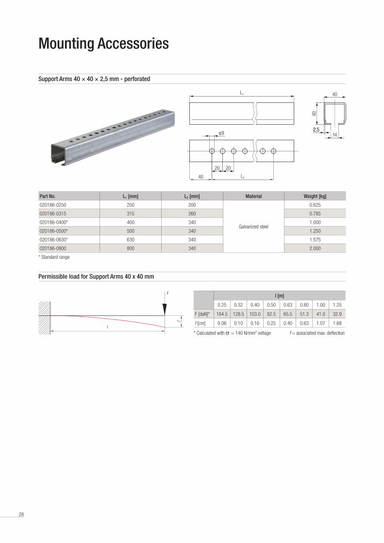
Part No. L1 [mm] L2 [mm] Material Weight [kg]
020186-0250 250 200
Galvanized steel
0 .625
020186-0315 315 260 0 .785
020186-0400* 400 340 1 .000
020186-0500* 500 340 1 .250
020186-0630* 630 340 1 .575
020186-0800 800 340 2 .000
* Standard range
Mounting Accessories
* Calculated with σ = 140 N/mm2 voltage f = associated max . deflection
I [m]
0 .25 0 .32 0 .40 0 .50 0 .63 0 .80 1 .00 1 .25
F [daN]* 164 .5 128 .5 103 .0 82 .5 65 .5 51 .3 41 .0 32 .9
f [cm] 0 .06 0 .10 0 .16 0 .25 0 .40 0 .63 1 .07 1 .68
Permissible load for Support Arms 40 x 40 mm
f
F
I
Support Arms 40 × 40 × 2,5 mm - perforated
L1
40
ø 9
40
2,514
L2
2020
40
2.5

29
Mounting Accessories
Holder for Support Arms 40 × 40 × 2,5 for screw mounting with 2-holed connector plate
125
8041 110
645
41,3 4
ø 11
41.3
Part No. Description Suitable for Support Arm Weight [kg] 020282 Galvanized steel 020186 1 .000
Holder for Support Arms 40 × 40 × 2,5
Part No. Description Suitable for Support Arm Weight [kg] 020286 Unplated steel with galvanized hardware 020186 0 .730
125
41
441,3 12 x 45˚41.3

30
Mounting Accessories
Girder Clips, non-twistable, clamping thickness 6 - 25 mm
Part No. Description Weight [kg] 020181-08 Galvanized steel 0 .190
Clamping thickness s [mm] 6-25 Installation height h [mm] 32-40
30
50
8M8
s
h
Part No. Description Weight [kg] 020180-08X36 Galvanized steel 0 .220
020480-08X36 Stainless steel (V4A) 0 .220
Girder Clips, clamping thickness 18 - 36 mm
Clamping thickness s [mm] 18-20 20-24 24-28 28-32 32-36 Installation height h [mm] 42-44 44-48 48-52 52-56 56-60
70
s 8
h
M8
Girder Clips, clamping thickness 4 - 20 mm
Part No. Description Weight [kg] 020180-08* Galvanized steel 0 .150
020480-08 Stainless steel (V4A) 0 .150
* Standard range
Clamping thickness s [mm] 4 6 8 10 12 16 20 Installation height h [mm] 31 32 33 34 35 37 40
60
s
M8
50
h
31
Mounting Accessories
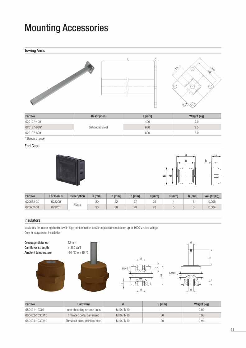
End Caps
Part No. For C-rails Description a [mm] b [mm] c [mm] d [mm] s [mm] h [mm] Weight [kg]
020662-30 023200Plastic
30 32 27 29 4 18 0 .005
020662-31 023201 30 30 28 28 5 16 0 .004
hb
sa
c
d
Part No. Hardware d I1 [mm] Weight [kg]
080401-10X10 Inner threading on both ends M10 / M10 – 0 .09
080402-1030X10 Threaded bolts, galvanized M10 / M10 30 0 .98
080403-1030X10 Threaded bolts, stainless steel M10 / M10 30 0 .98
Insulators
Insulators for indoor applications with high contamination and/or applications outdoors, up to 1000 V rated voltage
Only for suspended installation .
Creepage distance 62 mm
Cantilever strength > 350 daN
Ambient temperature -30 °C to +85 °C
Part No. Description L [mm] Weight [kg]
020197-400
Galvanized steel
400 2 .0
020197-630* 630 2 .5
020197-800 800 3 .0
* Standard range
Towing Arms
8010040
Ø11
6L
d
d
9
9
40
SW40
l 1
d
14
d
SW40

32
Mounting Accessories
Junction Box for Power Feed, with Fittings, Clamps and Accessories
Junction Box for Power Feed, with Fittings, Clamps and Accessories
Part No. Designation Weight [kg]
080102-3 Junction Box with 3 poles 0 .300
080102-4 Junction Box with 4 poles 0 .310
080102-5 Junction Box with 5 poles 0 .320
Part No. Designation Weight [kg]
080103-3 Junction Box with 3 poles 0 .290
080103-4 Junction Box with 4 poles 0 .300
080103-5 Junction Box with 5 poles 0 .310
110
7556,556.5110
7556,556.5
110
7556,556.5
110
7556,556.5
Mounting Comb 081046
For setting the rail holder spacing while mounting the Support Arms
70
80
35
4 x 70 (= 280)
4 x 80 (= 320)350
Part No. Designation Weight [kg]
081046* Mounting Comb 0 .190
* Standard range

33
Tools and Assembly Accessories
Grounding- and Short-circuit Device
Protective device during service and maintenance work on the conductor rail
Note: Several devices have to be used, depending on the number of poles (all live rails + ground rail) . The modular design of the Devices allows for any number of them
to be connected . Four Devices have to be used for a 3-phase system (1 x PE + 3 x PH = 4) .
Part No. Designation Weight [kg]
08-V015-0441* Grounding Device 813 with one pole 2 .2
* Standard range
160
322
Part No. Designation Weight [kg]
080021* Contact Grease 0 .250
* Standard range ** Packing unit: 5 tubes each 50 gram
Contact Grease for Connection Points (Aluminum rails)
Application: Use contact grease to avoid corrosion at contact points . A thin film is applied
with finger or brush to the faces of the conductor rail and the clamping area of the connectors .
One tube will last for about 200 connection points .
34
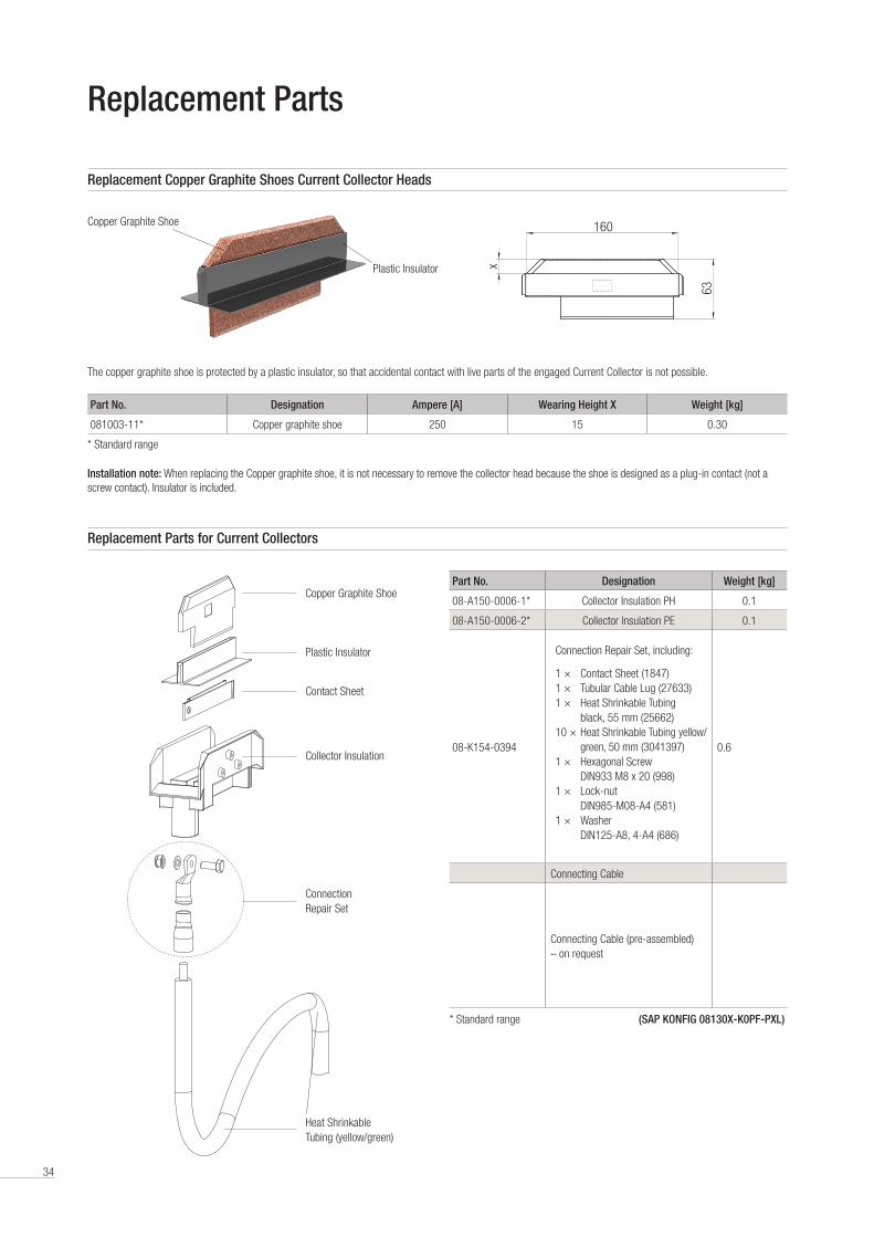
Replacement Parts
Replacement Copper Graphite Shoes Current Collector Heads
The copper graphite shoe is protected by a plastic insulator, so that accidental contact with live parts of the engaged Current Collector is not possible .
Installation note: When replacing the Copper graphite shoe, it is not necessary to remove the collector head because the shoe is designed as a plug-in contact (not a screw contact) . Insulator is included .
Part No. Designation Ampere [A] Wearing Height X Weight [kg]
081003-11* Copper graphite shoe 250 15 0 .30
* Standard range
63
160
x
Replacement Parts for Current Collectors
Copper Graphite Shoe
Plastic Insulator
Contact Sheet
Collector Insulation
Connection Repair Set
Heat Shrinkable Tubing (yellow/green)
Copper Graphite Shoe
Plastic Insulator
Part No. Designation Weight [kg]
08-A150-0006-1* Collector Insulation PH 0 .1
08-A150-0006-2* Collector Insulation PE 0 .1
08-K154-0394 0 .6
Connecting Cable
Connecting Cable (pre-assembled) – on request
* Standard range (SAP KONFIG 08130X-K0PF-PXL)
Connection Repair Set, including:
1 × Contact Sheet (1847) 1 × Tubular Cable Lug (27633) 1 × Heat Shrinkable Tubing black, 55 mm (25662)10 × Heat Shrinkable Tubing yellow/ green, 50 mm (3041397)1 × Hexagonal Screw DIN933 M8 x 20 (998)1 × Lock-nut DIN985-M08-A4 (581)1 × Washer DIN125-A8, 4-A4 (686)

Conductix-Wampfler – the complete program
Your Applications – our Solutions
Conductor rails from Conductix-Wampfler represent only one of the many solutions made possible by the broad spectrum of
Conductix-Wampfler components for the transport of energy, data and fluid media . The solutions we deliver for your applications
are based on your specific requirements . In many cases, a combination of several different Conductix-Wampfler systems can prove
advantageous . You can count on all of Conductix-Wampfler’s Business Units for hands-on engineering support – coupled with the
perfect solution to meet your energy management and control needs .
Jib booms
Complete with tool transporters, reels,
or an entire media supply system –
here, safety and flexibility are key to
the completion of difficult tasks .
Conductor rails
Whether they‘re enclosed conductor
rails or expandable single-pole
systems, the proven conductor rails
by Conductix-Wampfler reliably move
people and material .
Non-insulated conductor rails
Extremely robust, non-insulated
conductor rails with copper heads or
stainless steel surfaces provide the
ideal basis for rough applications, for
example in steel mills or shipyards .
Motorized Cable & Hose Reels
Motorized reels by Conductix-
Wampfler hold their own wherever
energy, data, media and fluids have
to cover the most diverse distances
within a short amount of time – in all
directions, fast and safe .
Spring Cable & Hose Reels
With their robust and efficient design
Spring Cable and Hose Reels from
Conductix-Wampfler are unbeatably
reliable in supplying energy, signals,
data and fluids to a vast range of
tools, cranes and vehicles .
Festoon systems
It‘s hard to imagine Conductix-
Wampfler cable trolleys not being
used in virtually every industrial
application . They‘re reliable and
robust and available in an enormous
variety of dimensions and designs .
Retractors and Balancers
Our wide range of high reliable
retractors and balancers remove the
load from your shoulders and allow
you to reach top productivity .
Inductive Power Transfer IPT®
The no-contact system for transferring
energy and data . For all tasks that
depend on high speeds and absolute
resistance to wear .
Slip ring assemblies
Whenever things are really “moving
in circles”, the proven slip ring
assemblies by Conductix-Wampfler
ensure the flawless transfer of energy
and data . Here, everything revolves
around flexibility and reliability!
Conveyor systems
Whether manual, semiautomatic
or with Power & Free – flexibility
is achieved with full customization
concerning layout and location .
Energy guiding chains
The “Jack of all trades” when it comes
to transferring energy, data, air and
fluid hoses . With their wide range,
these energy guiding chains are the
ideal solution for many industrial
applications .
www.conductix.com
KAT0
813-
0002
g-E
© C
ondu
ctix-
Wam
pfler
| 20
17 |
Subj
ect t
o Te
chni
cal M
odifi
catio
ns W
ithou
t Prio
r Not
ice Conductix-Wampfler
has just one critical mission:
To provide you with energy and
data transmission systems that
will keep your operations up
and running 24/7/365 .
To contact your nearest
sales office, please refer to:
www.conductix.com/contact-search


![Insulated Conductor Rail SinglePowerLine Program 0812 · 2020. 8. 27. · Type 081217 081213 081214 08121C 08121D 081215 081216 Current load [A] At 100% duty cycle and 35 °C (rated](https://img.pdfslide.us/doc/110x75/60db1531e3da33117d3be7b4/insulated-conductor-rail-singlepowerline-program-0812-2020-8-27-type-081217.jpg)