Embed Size (px)
Citation preview

Instrumentation of a compact random-access photostimulator based on acousto-opticdeflectorsYafeng Liu, Yuan Zhao, Xiaohua Lv, Yiding Li, Xiaohui Zhang, Jie Zhang, Liping Wang, and Shaoqun Zeng Citation: Review of Scientific Instruments 83, 025116 (2012); doi: 10.1063/1.3689954 View online: http://dx.doi.org/10.1063/1.3689954 View Table of Contents: http://scitation.aip.org/content/aip/journal/rsi/83/2?ver=pdfcov Published by the AIP Publishing
This article is copyrighted as indicated in the article. Reuse of AIP content is subject to the terms at: http://scitationnew.aip.org/termsconditions. Downloaded to IP:
219.223.216.212 On: Tue, 07 Jan 2014 03:16:26

REVIEW OF SCIENTIFIC INSTRUMENTS 83, 025116 (2012)
Instrumentation of a compact random-access photostimulator basedon acousto-optic deflectors
Yafeng Liu,1,2 Yuan Zhao,1,2 Xiaohua Lv,1,2 Yiding Li,3,4 Xiaohui Zhang,3 Jie Zhang,5
Liping Wang,5 and Shaoqun Zeng1,2,a)
1Britton Chance Center for Biomedical Photonics, Wuhan National Laboratory for Optoelectronics,Wuhan 430074, China2Key Laboratory of Biomedical Photonics of Ministry of Education, Huazhong University of Science andTechnology, Wuhan 430074, China3Institute of Neuroscience, State Key Laboratory of Neuroscience, Shanghai Institutes for Biological Sciences,Chinese Academy of Sciences, Shanghai 200031, China4Graduate School of CAS, Chinese Academy of Sciences, China5Shenzhen Key Lab of Neuropsychiatric Modulation, Shenzhen Institutes of Advanced Technology, ChineseAcademy of Sciences, Shenzhen 518055, China
(Received 17 August 2011; accepted 2 February 2012; published online 29 February 2012)
Recently developed optogenetics provides a fast, non-invasive, and efficient method for cell activa-tion. However, it is difficult for the optical stimulators used for optogenetics to realize selective multi-site fast activation. In this paper, we developed a random-access photostimulator based on a pair ofperpendicularly oriented acousto-optic deflectors. Precise laser targeting in the x-y plane was verified,and the lateral spatial resolution of laser intensity after the objective was measured as ∼1.38 μm. Pho-tostimulaton of ChETA-expressing astrocytes induced reliable inward currents only if the laser beamwas directed onto the targeted cell. In the ChR2-expresing neuron, multiple locations along two den-drites were stimulated, and spatiotemporal integration was observed in the soma with fast multi-siteactivation. These results demonstrated that this random-access photostimulator would be a powerfultool for selective multi-site fast activation. The compact and modular design of this photostimulatormakes it easily integrated with different commercial microscopes, and thus widely popularized inmany laboratories. © 2012 American Institute of Physics. [http://dx.doi.org/10.1063/1.3689954]
I. INTRODUCTION
Selective activation of multiple cells or neurites is verysignificant for investigating integration and computation inneurons. In the last few years, the combination of molecu-lar genetic engineering and optical stimulation has boostedthe appearance of a new technology–optogenetics, which pro-vides a fast, non-invasive, and accurate activation.1–3
Cells expressed light-sensitive channelrhodopsins can beactivated when they are illuminated by a beam of light. How-ever, light sources used in common fluorescence microscopesare wide-field light sources, which would activate all cellsor the whole neural circuits in the field of view (FOV).4
A laser scanning microscope equipped with galvanometer-driven scanning mirrors can realize the activation of multi-ple selective cells.5, 6 Nevertheless, the scanning speed and thetargeting positions are limited because of the inherent inertiaof the scanning mirrors. Recently, the spatial light modula-tor (SLM) was introduced to achieve selective activation in anon-inertial way.7, 8 However, the low refresh rate (∼60 Hz)and diffraction efficiency of SLM limit the application of thistechnology.9, 10 In contrast, acousto-optic deflector (AOD) hasthe advantage of fast random addressing and has been used todeliver laser non-inertia to multiple pre-selected sites for pho-tolysis of caged compounds in cultures.11–14 The good spatialselection will also make AOD suitable for selectively stimu-
a)Author to whom correspondence should be addressed. Electronic mail:[email protected].
lating light-sensitive channels such as ChR2 and a newly en-gineered channelrhodopsin-ChETA.15
In this paper, the instrumentation of a random-accessphotostimulation system for selective activation based on apair of perpendicularly oriented AODs is reported. First, weillustrate the optical and mechanical design of a random-access photostimulator using AODs and its integration witha commercial microscope. The photostimulating process wascontrolled by a custom-written software developed by LAB-VIEW. Subsequently, the performances of the phostimulatorincluding targeting accuracy, FOV uniformity, and lateral res-olution were evaluated. Finally, selective and fast activationof multiple locations were demonstrated using the ChETA-expressing cultured astrocytes and ChR2-expressing corticalneuron.
II. SYSTEM DESIGN
The optical stimulation system named QuickView-Stimis illustrated in Figure 1(a). The laser source is a diode-pumped solid-state blue laser (MLL-III-473, λ = 473 nm,Changchun New Industries Optoelectronics Tech, China).The laser was coupled into a single mode fiber (SMF, NA= 0.11, OZ, Canada) which was equipped with two lensesright at the two ends. To enhance the coupling efficiency,an aspheric lens (focal length, 4.5 mm) was used before theSMF (coupling efficiency >50%). An achromatic lens (fo-cal length, 30 mm) was fixed right at the output end for laser
0034-6748/2012/83(2)/025116/5/$30.00 © 2012 American Institute of Physics83, 025116-1
This article is copyrighted as indicated in the article. Reuse of AIP content is subject to the terms at: http://scitationnew.aip.org/termsconditions. Downloaded to IP:
219.223.216.212 On: Tue, 07 Jan 2014 03:16:26

025116-2 Liu et al. Rev. Sci. Instrum. 83, 025116 (2012)
FIG. 1. (Color online) Photostimulator based on acousto-optic deflectors. (a) Optical schematic diagram. The two rectangles with broken lines indicate thescanning unit and the microscope. (b) Photo of the photostimulator combined with a commercial FN1 microscope.
collimation, and a laser beam 4.6 mm in diameter was ob-tained. A halfwave plate was used to adjust the polarizationdirection of the collimating laser beam. After a pair of per-pendicularly oriented AODs (DTSXY-400-473, AA, France)and a scan lens, the laser was directed into the commer-cial microscope (FN1, Nikon, Japan) by a dual port (Y-QT,Nikon, Japan), which consisted of one dichroic mirror and oneemission filter. The dichroic mirror (DM505) was utilized toreflect the 473 nm laser to the microscope and to transmitfluorescence for CCD (CoolSNAP HQ2, Photometrics, USA)imaging together with a bandpass filter. The scan lens and thetube lens in the microscope comprised a relay system to imagethe AODs onto the back focal plane of the objective. The scanlens with a focal length of 180 mm was used in the system tobalance the scanning range with the spatial resolution. Thenthe scanning beam was focused onto the samples by objective.
The optical elements of the system, except the laser, wereall assembled on one raised platform (the scanning unit inFigure 1(b), indicated by the yellow arrow). In order to in-tegrate the scanning unit into the microscope, eight tappedholes were made in the two profiles of the main body of themicroscope. Two triangular frames were designed and fixedonto the main body by eight M6 screws. After those prepa-rations, the photostimulation system was firmly fixed ontothe microscope and integrated into a uniform unit. In orderto control the scanning of the AODs, an AOD driver wasbuilt, which consisted of a direct digital synthesizer (DDSPA-B415b-0, AA, France) and a power amplifier (AMPA-B-30,AA, France), which supplied sine electrical signals to the
acousto-optic deflector crystal. This driving box design alsoaccorded with the modular concept and so it was easily in-stalled onto the instrument stand.
One application routine termed “random photostim”(RPS) was developed for controlling the photostimulationprocess using LABVIEW (National Instruments, USA). Itworked in association with IMAGE PRO-PLUS (IPP, MediaCybernetics, USA) software (Figure 2(a)), which was used toacquire images from CCD. Before photostimulation, regionsof interest (ROIs) were pre-selected on the image taken byIPP. Then the position information of these ROIs was savedas an “.aoi” file and imported into RPS (Figure 2(b)). In theRPS, the ROIs position was converted into frequency controlwords of AODs, which determined the laser delivery and tar-geting. The stimulation parameters such as stimulation mode,scanning mode, working mode, stimulation power, and stim-ulation time and interval can be configured in RPS. A mul-tifunction data acquisition (DAQ) card (PCI-6259, NI, USA)was used to accomplish control of the AODs’ drivers or otherperipheral devices.
III. RESULTS
A. General performance test
After completing the design and debugging, the func-tions of the stimulation system were carefully tested. In or-der to measure targeting accuracy, fluorescence images oflaser spot in different positions were synchronously recorded
FIG. 2. (Color online) The software for controlling random-access photostimulation. (a) Block flow diagram. The rectangle with a broken line indicates assistantoperations in IPP software. (b) RPS program interface displayed in front panel in LABVIEW.
This article is copyrighted as indicated in the article. Reuse of AIP content is subject to the terms at: http://scitationnew.aip.org/termsconditions. Downloaded to IP:
219.223.216.212 On: Tue, 07 Jan 2014 03:16:26

025116-3 Liu et al. Rev. Sci. Instrum. 83, 025116 (2012)
FIG. 3. (Color online) System performance. (a) Relationship between actual location and the expected location. (b) Relationship between laser power andcontrolling voltage into AOD. (c) Laser power distribution in the FOV after adjustment of controlling voltage to AOD. (d) Spatial resolution (1.38 μm, fullwidth of half maximum of fluorescence spots). (All data were obtained with a 40× water objective and a solution containing 3.75 μM FITC. Laser power afterthe objective is 0.6 mW).
while laser beam was moved along a line to illuminate flu-orescence solution containing 3.75 μM fluorescein isothio-cyanate (FITC) by supplying the signals of intended positionsinto AODs. Then the actual positions of laser spot were mea-sured from these fluorescence images by IPP software. Therelation of actual location and intended location was plottedin Figure 3(a), which showed a highly precise targeting thatwas an essential parameter for optical stimulation. Next thelaser power after the objective was measured by supplying in-cremental voltage signal into AODs. The correlation betweenthe laser power after the objective and the controlling volt-age of the AOD was shown in Figure 3(b). The amplitudeof the driving signal affected the diffraction efficiency of thelaser traveling through the AOD, and thus determined outputpower after the objective. Continuously adjustable power wasindispensable for the activation of different samples, which iseasily achieved in our system.
Because light diffraction efficiency through AODs wasdependent on the frequency control word, the laser power af-ter AODs was different for varied controlling frequency inspite of the same voltage into AODs. Since this frequency de-termined the laser targeting location, the laser power varied atdifferent locations with the same controlling voltage. In orderto obtain the uniform illumination throughout the whole FOV,
the laser power was adjusted to the lowest value in the FOV byregulating the controlling voltage to AOD in each frequencyposition. In one example shown in Figure 3(c), the laserpower after adjustment in the FOV ranged from 5.90 mW to6.04 mW with a 2.5% variation. The laser power uniformityin the whole FOV is important for quantitative analysis of cellresponses. On the other hand, the sharpness of laser spot afterthe objective will determine the effect of selective activationof cells. Then the lateral profile of fluorescence spots afterthe objective was obtained from recorded fluorescence im-age by IPP software while laser beam illuminated FITC aque-ous solution. The lateral resolution (full width at half max-imum, with laser power of 0.6 mW) was calculated as 1.38± 0.10 μm in Figure 3(d), which was roughly identical at dif-ferent locations in either the x- or the y-direction. The lateralresolution is mainly dependent on the numeric aperture of theobjective. So x-y resolution is identical for varied laser poweror controlling voltage into AODs.
B. Selective excitation of ChETA-expressingastrocytes
As we know, astrocytes actively participate in neu-ronal transmission in the central nervous system. Selective
This article is copyrighted as indicated in the article. Reuse of AIP content is subject to the terms at: http://scitationnew.aip.org/termsconditions. Downloaded to IP:
219.223.216.212 On: Tue, 07 Jan 2014 03:16:26
025116-4 Liu et al. Rev. Sci. Instrum. 83, 025116 (2012)
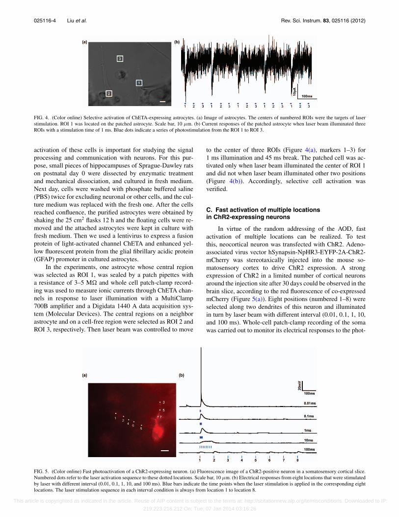
FIG. 4. (Color online) Selective activation of ChETA-expressing astrocytes. (a) Image of astrocytes. The centers of numbered ROIs were the targets of laserstimulation. ROI 1 was located on the patched astrocyte. Scale bar, 10 μm. (b) Current responses of the patched astrocyte when laser beam illuminated threeROIs with a stimulation time of 1 ms. Blue dots indicate a series of photostimulation from the ROI 1 to ROI 3.
activation of these cells is important for studying the signalprocessing and communication with neurons. For this pur-pose, small pieces of hippocampuses of Sprague-Dawley ratson postnatal day 0 were dissected by enzymatic treatmentand mechanical dissociation, and cultured in fresh medium.Next day, cells were washed with phosphate buffered saline(PBS) twice for excluding neuronal or other cells, and the cul-ture medium was replaced with the fresh one. After the cellsreached confluence, the purified astrocytes were obtained byshaking the 25 cm2 flasks 12 h and the floating cells were re-moved and the attached astrocytes were kept in culture withfresh medium. Then we used a lentivirus to express a fusionprotein of light-activated channel ChETA and enhanced yel-low fluorescent protein from the glial fibrillary acidic protein(GFAP) promoter in cultured astrocytes.
In the experiments, one astrocyte whose central regionwas selected as ROI 1, was sealed by a patch pipettes witha resistance of 3–5 M� and whole cell patch-clamp record-ing was used to measure ionic currents through ChETA chan-nels in response to laser illumination with a MultiClamp700B amplifier and a Digidata 1440 A data acquisition sys-tem (Molecular Devices). The central regions on a neighborastrocyte and on a cell-free region were selected as ROI 2 andROI 3, respectively. Then laser beam was controlled to move
to the center of three ROIs (Figure 4(a), markers 1–3) for1 ms illumination and 45 ms break. The patched cell was ac-tivated only when laser beam illuminated the center of ROI 1and did not when laser beam illuminated other two positions(Figure 4(b)). Accordingly, selective cell activation wasverified.
C. Fast activation of multiple locationsin ChR2-expressing neurons
In virtue of the random addressing of the AOD, fastactivation of multiple locations can be realized. To testthis, neocortical neuron was transfected with ChR2. Adeno-associated virus vector hSynapsin-NpHR3-EYFP-2A-ChR2-mCherry was stereotaxically injected into the mouse so-matosensory cortex to drive ChR2 expression. A strongexpression of ChR2 in a limited number of cortical neuronsaround the injection site after 30 days could be observed in thebrain slice, according to the red fluorescence of co-expressedmCherry (Figure 5(a)). Eight positions (numbered 1–8) wereselected along two dendrites of this neuron and illuminatedin turn by laser beam with different interval (0.01, 0.1, 1, 10,and 100 ms). Whole-cell patch-clamp recording of the somawas carried out to monitor its electrical responses to the phot-
FIG. 5. (Color online) Fast photoactivation of a ChR2-expressing neuron. (a) Fluorescence image of a ChR2-positive neuron in a somatosensory cortical slice.Numbered dots refer to the laser activation sequence to these dotted locations. Scale bar, 10 μm. (b) Electrical responses from eight locations that were stimulatedby laser with different interval (0.01, 0.1, 1, 10, and 100 ms). Blue bars indicate the time points when the laser stimulation is applied in the corresponding eightlocations. The laser stimulation sequence in each interval condition is always from location 1 to location 8.
This article is copyrighted as indicated in the article. Reuse of AIP content is subject to the terms at: http://scitationnew.aip.org/termsconditions. Downloaded to IP:
219.223.216.212 On: Tue, 07 Jan 2014 03:16:26

025116-5 Liu et al. Rev. Sci. Instrum. 83, 025116 (2012)
stimulation. As shown in Figure 5(b), with 100 ms interval,individual responses to photostimulation on each positionwere clearly observed. As the interval was reduced, responseswere temporally summed up, forming marked subthresholddepolarization with increased amplitude. When interval was0.01 ms, the depolarization reached firing threshold, and anaction potential was evoked.
These results showed that arbitrary locations were effi-ciently activated in an ultrafast way, resulting in spatiotem-poral integration of multiple inputs at the soma. The fastrandom addressing of the AOD-based photosimulator couldbe applied for studying synaptic integration and neuronalcomputation.
IV. DISCUSSION
We have established a random access photostimulatorthat allows fast selective activation of cells. We used this sys-tem to complete selective activation of astrocytes and neu-rons, which profited from the choice of AODs. Comparedwith SLM, AODs have better beam quality, higher diffractionefficiency (>80% for two-dimensional AODs), and faster ad-dressing (<10 μs).
In the system, stimulation time, stimulation intensity,stimulation mode, scanning method, and other parameters canbe set up handily and skillfully. So various stimulation pat-terns can be easily achieved for the activation of differenttypes of cells in multiple sites. The small spot size of 1.38 μmis easy to achieve the selective activation of cells. The lat-eral resolution in activating cells was measured as 17 μmwhen laser power after the 40× objective was 30 μW, whichdemonstrated our system was of good selection in lateral di-rection. In addition, we also proved that lateral resolution wasdependent on laser power and lower laser power could ob-tain higher resolution.16 However, the axial resolution was150 μm, which demonstrated this photostimulator had weakeraxial resolution when 473 nm laser was used in this system.Recently, femtosecond pulse laser has been used in a few sys-tems for improving the activation resolution.6, 8, 17 Therefore,combined with femtosecond pulse laser, our system will alsoimprove the spatial resolution. The performance of our systemcan be extended by the integration of a second laser and AODsfor selective activation and inactivation of multiple neurons.18
Our system worked very stably and effectively because ofits modular design and compactness. In addition, the graph-
ical development environment based on the LABVIEW lan-guage made this application program easy to use. In its currentversion, the size of the scanning box was only 300 mm × 220mm × 180 mm, and its weight was only about 3 kg. The smallvolume and weight allowed it to be easily integrated with dif-ferent kinds of commercial microscopes produced by diversemicroscope producers such as Nikon Corp., Olympus Corp.,and so on. These characteristics and advantages are very re-markable and highly beneficial for its popularization in manylaboratories.
ACKNOWLEDGMENTS
This work was supported by NSFC Grant Nos. 30927001and 30925013.
1K. Deisseroth, Nat. Methods 8, 26 (2011).2S. Peron and K. Svoboda, Nat. Methods 8, 30 (2011).3J. E. Toettcher, C. A. Voigt, O. D. Weiner, and W. A. Lim, Nat. Methods 8,35 (2011).
4E. S. Boyden, F. Zhang, E. Bamberg, G. Nagel, and K. Deisseroth, Nat.Neurosci. 8, 1263 (2005).
5H. Wang, J. Peca, M. Matsuzaki, K. Matsuzaki, J. Noguchi, L. Qiu,D. Wang, F. Zhang, E. Boyden, K. Deisseroth, H. Kasai, W. C. Hall,G. Feng, and G. J. Augustine, Proc. Natl. Acad. Sci. U.S.A. 104, 8143(2007).
6D. W. Tank and J. P. Rickgauer, Proc. Natl. Acad. Sci. U. S.A. 106, 15025(2009).
7V. Nikolenko, D. S. Peterka, and R. Yuste, J. Neural Eng. 7, 045001(2010).
8E. Papagiakoumou, F. Anselmi, A. Begue, V. de Sars, J. Gluckstad,E. Y. Isacoff, and V. Emiliani, Nat. Methods 7, 848 (2010).
9V. Nikolenko, B. O. Watson, R. Araya, A. Woodruff, D. S. Peterka, andR. Yuste, Front Neural Circuits 2, 5 (2008).
10L. Golan, I. Reutsky, N. Farah, and S. Shoham, J. Neural Eng. 6, 066004(2009).
11S. Shoham, D. H. O’Connor, D. V. Sarkisov, and S. S. Wang, Nat. Methods2, 837 (2005).
12P. Saggau, B. E. Losavio, and V. Iyer, J. Biomed. Opt. 14, 064033 (2009).13S. Shoham and K. Deisseroth, J. Neural Eng. 7, 040201 (2010).14B. E. Losavio, V. Iyer, S. Patel, and P. Saggau, J. Neural Eng. 7, 045002
(2010).15K. Deisseroth, L. A. Gunaydin, O. Yizhar, A. Berndt, V. S. Sohal, and
P. Hegemann, Nat. Neurosci. 13, 387-U27 (2010).16K. Wang, Y. Liu, Y. Li, Y. Guo, P. Song, X. Zhang, S. Zeng, and Z. Wang,
PLoS ONE 6, e28468 (2011).17A. Vaziri, B. K. Andrasfalvy, B. V. Zemelman, and J. Y. Tang, Proc. Natl.
Acad. Sci. U.S.A. 107, 11981 (2010).18F. Zhang, L.-P. Wang, M. Brauner, J. F. Liewald, K. Kay, N. Watzke,
P. G. Wood, E. Bamberg, G. Nagel, A. Gottschalk, and K. Deisseroth,Nature (London) 446, 633 (2007).
This article is copyrighted as indicated in the article. Reuse of AIP content is subject to the terms at: http://scitationnew.aip.org/termsconditions. Downloaded to IP:
219.223.216.212 On: Tue, 07 Jan 2014 03:16:26


![siemens.com/processautomation Process Instrumentation ...elmec.ae/uploads/SIEMENS brochure- Instruments.pdf · SITRANS TH100 [1] Pt100 transmitter. Low-cost and compact, configurable](https://img.pdfslide.us/doc/110x75/5f6db1aa3f65e9206d0a5bdb/process-instrumentation-elmecaeuploadssiemens-brochure-instrumentspdf.jpg)