Embed Size (px)
Citation preview
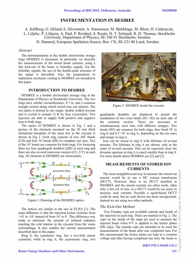
Figure 1: Drawing of the DESIREE optics.
Figure 2: DESIREE inside the cryostat.
INSTRUMENTATION IN DESIREE
University, Department of Physics, SE-106 91 Stockholm, Sweden, H. Danared, European Spallation Source, Box 176, SE-221 00 Lund, Sweden
Abstract The instrumentation in the double electrostatic storage
rings DESIREE is discussed, In particular, we describe the measurements of the stored beam currents, using a fast kick-out of the beam or Schottky signals. For the Schottky signals, the use of the double-peak structure of the signal is described. Also the preparations to implement stochastic cooling in DESIREE are included in this paper.
INTRODUCTION TO DESIREE DESIREE is a double electrostatic storage ring at the
Department of Physics at Stockholm University. The two rings have similar circumferences, 8.7 m, and a common straight section along which stored ions can interact. The ion optics is housed in one single, double walled cryostat and is cooled to around 13 K by four cryocoolers. Two injectors are able to supply both positive and negative ions to both rings.
The optics of DESIREE is shown in Fig. 1 and a picture of the elements mounted on the 20 mm thick aluminium baseplate of the inner box in the cryostat is shown in Fig. 2. Each ring consists of two 160° bends (CD) and four 10° bends (DE) to complete one turn. Two of the 10° bends are common for both rings. For focussing there are four quadrupole doublets (QD) in each ring and there are also several transverse steerers (CC, CV) in each ring. All elements in DESIREE are electrostatic.
The lattices are similar to the one in ELISA [1]. The main difference is that the injection kicker switches from +10° to -10° instead of from 10° to 0°. This difference was made to minimize the amount of infrared radiation reaching the cold interior in the cryostat from the warm surroundings. It also enables the current measurement described later in this paper.
Ring S, the symmetric ring, has a two-fold mirror symmetry while in ring A, the asymmetric ring, two
quadrupole doublets are displaced to permit the installation of two extra bends (D1, D2) on each side of the common section. These are necessary to simultaneously store ions with different energies. Two bends (D3) are common for both rings, they bend 10° in ring S and 0.5°-10° in ring A, depending on the ion mass and energy in ring A.
Ions can be stored in ring S with lifetimes of several minutes. The lifetimes in ring A are shorter, only in the order of several seconds. This can be expected, since the dynamic aperture in ring A is much smaller than in ring S. For more details about DESIREE see [2] and [3]
MEASUREMENTS OF STORED ION CURRENTS
The most straightforward way to measure the stored ion current would be to use a DC current transformer (DCCT). However, there is no DCCT installed in DESIREE and the stored currents are often weak, often only a few nA or less, so a DCCT would be too noisy to measure such currents. Possibly a squid-based DCCT could be used, but no such device has been incorporated. Instead we are using two other methods.
The Kick-Out Method Two Faraday cups are available outside and inside of
the injection in each ring. These are marked in Fig. 2. The cups on the inside of the rings are used to measure the injected beam when 0 V is applied to the kicker plates (DE (inj)). The outside cups are intended to be used for measurements of the beam after one completed turn. For this measurement the kicker plates are kept at a constant voltage and after having completed one turn, the beam is
A. Källberg, G. Eklund, S. Silverstein, A. Simonsson, M. Björkhage, M. Blom, H. Cederqvist, L. Liljeby, P. Löfgren, A. Paál, P. Reinhed, S. Rosén, H. T. Schmidt, R. D. Thomas, Stockholm
Proceedings of IBIC2015, Melbourne, Australia MOPB040
Beam Charge Monitors and Other Instruments
ISBN 978-3-95450-176-2
131 Cop
yrig
ht©
2015
CC
-BY-
3.0
and
byth
ere
spec
tive
auth
ors
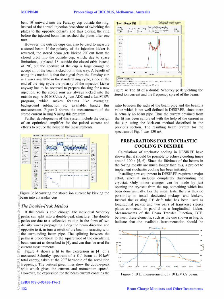
Figure 5: BTF measurement of a 10 keV C2- beam.
Figure 3: Measuring the stored ion current by kicking thebeam into a Faraday cup
Figure 4: The fit of a double Schottky peak yielding the stored ion current and the frequency spread of the beam.
bent 10° outward into the Faraday cup outside the ring, instead of the normal injection procedure of switching the plates to the opposite polarity and thus closing the ring before the injected beam has reached the plates after one turn.
However, the outside cups can also be used to measure a stored beam. If the polarity of the injection kicker is reversed, the stored beam gets kicked 20° out from the closed orbit into the outside cup, which, due to space limitations, is placed 18° outside the closed orbit instead of 20°, but the aperture of the cup is large enough to accept all of the beam kicked out in this way. A benefit of using this method is that the signal from the Faraday cup is always available in the standard ring cycle, since at the end of the ring cycle the polarity of the injection kicker anyway has to be reversed to prepare the ring for a new injection, so the stored ions are always kicked into the outside cup. A 20 MS/ch/s Agilent ADC and a LabVIEW program, which makes features like averaging, background subtraction etc. available, handle this measurement. Figure 3 shows the measurement of the stored current in ring S using this program.
Further developments of this system include the design of an optimized amplifier for the pulsed current and efforts to reduce the noise in the measurements.
The Double-Peak Method If the beam is cold enough, the individual Schottky
peaks can split into a double-peak structure. The double peaks are due to a collective motion in the form of two density waves propagating along the beam direction and opposite to it, in turn a result of the beam interacting with the surrounding beam pipe. The splitting between the peaks is proportional to the square root of the circulating beam current as described in [4], and can thus be used for current measurements.
Figure 4 shows a fit to the expression in [4] of a measured Schottky spectrum of a C2
– beam at 10 keV total energy, taken at the 23rd harmonic of the revolution frequency. The vertical green lines show the double-peak split which gives the current and momentum spread. However, the expression for the beam current contains the
ratio between the radii of the beam pipe and the beam, a value which is not well defined in DESIREE, since there is actually no beam pipe. Thus the current obtained from the fit has been calibrated with the help of the current in the cup using the kick-out method described in the previous section. The resulting beam current for the spectrum of Fig. 4 was 130 nA.
PREPARATIONS FOR STOCHASTIC COOLING IN DESIREE
Calculations of stochastic cooling in DESIREE have shown that it should be possible to achieve cooling times around 100 s [5, 6]. Since the lifetimes of the beams in the S-ring mostly are much longer than this, a project to implement stochastic cooling has been initiated.
Installing new equipment in DESIREE requires a major effort, since it includes completely dismounting the cryostat. Only minor changes can be made by just opening the cryostat from the top, something which has been done annually. For the initial tests, there is thus no possibility to install dedicated pickups and kickers. Instead the existing RF drift tube has been used as longitudinal pickup and two pairs of transverse steerer plates connected in parallel as a longitudinal kicker. Measurements of the Beam Transfer Function, BTF, between these elements, such as the one shown in Fig. 5, indicate that the available instrumentation should be
MOPB040 Proceedings of IBIC2015, Melbourne, Australia
ISBN 978-3-95450-176-2
132Cop
yrig
ht©
2015
CC
-BY-
3.0
and
byth
ere
spec
tive
auth
ors
Beam Charge Monitors and Other Instruments
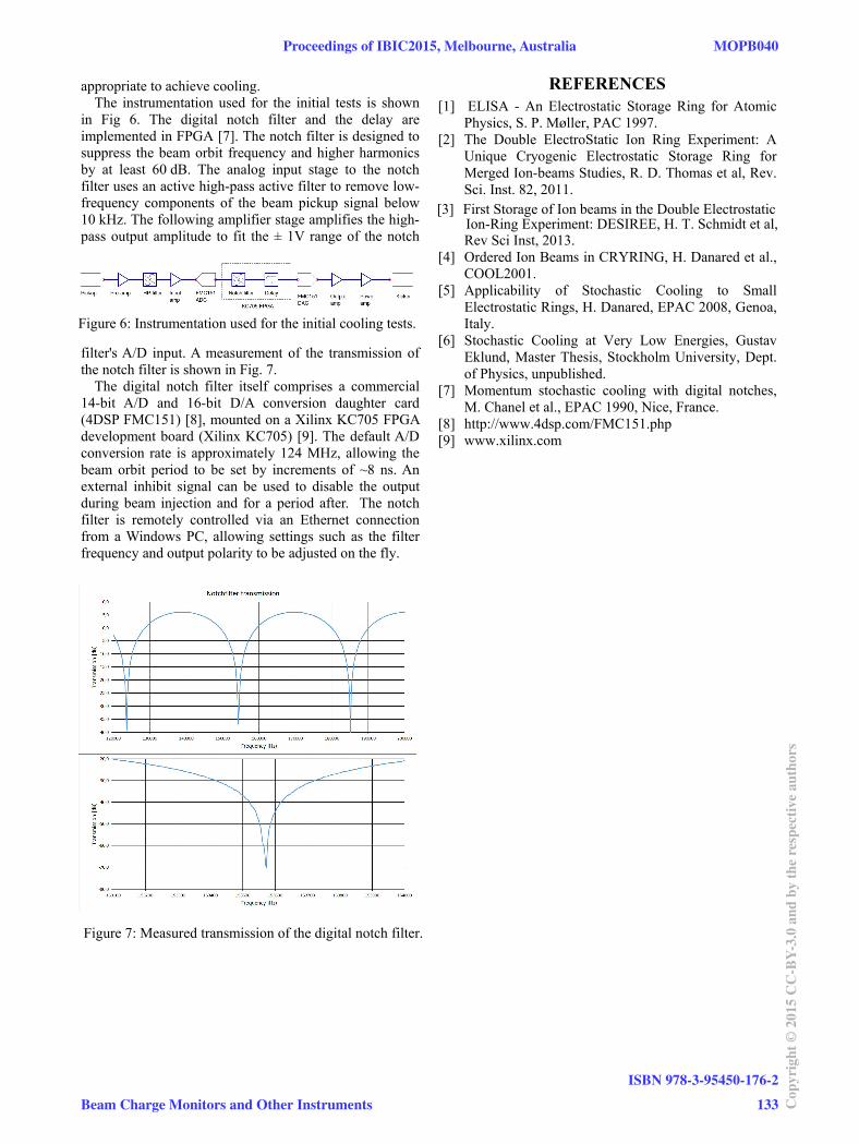
Figure 6: Instrumentation used for the initial cooling tests.
Figure 7: Measured transmission of the digital notch filter.
appropriate to achieve cooling. The instrumentation used for the initial tests is shown
in Fig 6. The digital notch filter and the delay are implemented in FPGA [7]. The notch filter is designed to suppress the beam orbit frequency and higher harmonics by at least 60 dB. The analog input stage to the notch filter uses an active high-pass active filter to remove low-frequency components of the beam pickup signal below 10 kHz. The following amplifier stage amplifies the high-pass output amplitude to fit the ± 1V range of the notch
filter's A/D input. A measurement of the transmission of the notch filter is shown in Fig. 7.
The digital notch filter itself comprises a commercial 14-bit A/D and 16-bit D/A conversion daughter card (4DSP FMC151) [8], mounted on a Xilinx KC705 FPGA development board (Xilinx KC705) [9]. The default A/D conversion rate is approximately 124 MHz, allowing the beam orbit period to be set by increments of ~8 ns. An external inhibit signal can be used to disable the output during beam injection and for a period after. The notch filter is remotely controlled via an Ethernet connection from a Windows PC, allowing settings such as the filter frequency and output polarity to be adjusted on the fly.
REFERENCES [1] ELISA - An Electrostatic Storage Ring for Atomic
Physics, S. P. Møller, PAC 1997. [2] The Double ElectroStatic Ion Ring Experiment: A
Unique Cryogenic Electrostatic Storage Ring for Merged Ion-beams Studies, R. D. Thomas et al, Rev. Sci. Inst. 82, 2011.
Ion-Ring Experiment: DESIREE, H. T. Schmidt et al,
[3] First Storage of Ion beams in the Double Electrostatic
Rev Sci Inst, 2013. [4] Ordered Ion Beams in CRYRING, H. Danared et al.,
COOL2001. [5] Applicability of Stochastic Cooling to Small
Electrostatic Rings, H. Danared, EPAC 2008, Genoa, Italy.
[6] Stochastic Cooling at Very Low Energies, Gustav Eklund, Master Thesis, Stockholm University, Dept. of Physics, unpublished.
[7] Momentum stochastic cooling with digital notches, M. Chanel et al., EPAC 1990, Nice, France.
[8] http://www.4dsp.com/FMC151.php [9] www.xilinx.com
Proceedings of IBIC2015, Melbourne, Australia MOPB040
Beam Charge Monitors and Other Instruments
ISBN 978-3-95450-176-2
133 Cop
yrig
ht©
2015
CC
-BY-
3.0
and
byth
ere
spec
tive
auth
ors