Embed Size (px)
Citation preview

INSTRUMENTATION FOR SPECTROSCOPYAND EXPERIMENTAL STUDIES OF SOMEATOMS, MOLECULES AND CLUSTERS
SAMULI URPELAINEN
Department of PhysicsUniversity of OuluFinland
REPORT SERIES IN PHYSICAL SCIENCES Report No. 58OULU 2009 • UNIVERSITY OF OULU

ISBN 978-951-42-9266-9
ISSN 1239-4327
OULU UNIVERSITY PRESS
Oulu 2009

To my parents


i
Urpelainen, Samuli Tapio: Instrumentation for spectroscopy and
experimental studies of some atoms, molecules and clusters
Department of PhysicsP.O. Box 3000FIN-90014 University of OuluFINLAND
Abstract
Experimental synchrotron radiation induced electron- and ion spectroscopiestogether with electron-ion and ion-ion coincidence techniques as well as elec-tron energy loss spectroscopy have been used to study the electronic prop-erties of several vapor phase samples. In this thesis studies of the electronicstructure and fragmentation of Sb4 clusters, photo- and Auger electron spec-troscopy of atomic Si and Pb as well as ultra high resolution VUV absorptionof vapor phase KF molecules have been performed. The instrumentation andtechniques used in the studies, especially the electron energy loss apparatusand the newly built ultra high resolution FINEST beamline branch, are pre-sented.
Key words: Synchrotron radiation, electron spectroscopy, electron energy lossspectroscopy, ion spectroscopy, electron-ion coincidence, ion-ion coincidence

ii

Acknowledgments
The present work was carried out in the Department of Physics of the Univer-sity of Oulu. I would like to thank the Head of the Department Prof. JukkaJokisaari, for placing the facilities at my disposal. I thank my supervisorsProf. Helena Aksela and Prof. Seppo Aksela for introducing me to thefascinating world of atomic physics and electron spectroscopy and for theirsupport and, especially, patience during the last phases of my thesis work. Iam extremely grateful to my supervisor Doc. Marko Huttula who has guidedme to the fields of experimental electron and ion spectroscopies and especiallyfor allowing me to speak my mind, which has created a good and open work-ing relationship as well as friendship. I thank Prof. Edwin Kukk for his helpwith the PEPICO experiments. I would like to express my gratitude to allthe past and present memebers of the Electron spectroscopy research groupfor such a nice and open working atmosphere, especially to Dr. Kari Jankalaand Johannes Niskanen for their sense of humor and for the many interestingand refreshing discussions about physics and life in general.
Most of the experimental work presented in this thesis has been carriedout in MAX-laboratory, Lund, Sweden, where I am fortunate to have hadthe opportunity to spend one and a half years in addition to the many beam-times. I would like to thank the director of MAX-lab, Prof. Nils Martenssonand Prof. Ralf Nyholm. Especially I would like to thank Dr. Thiagara-jan Balasubramanian for his guidance and friendship throughout my stayin MAX-lab. The whole staff of MAX-lab is acknowledged for the friendlyatmosphere in which it was such a pleasure to work.
Financially this work was supported by Vilho, Yrjo, and Kalle VaisalaFoundation, Magnus Ehrnrooth Foundation, Tauno Tonning Foundation, theNational Graduate School in Materials Physics as well as the Marie CurieEarly Stage Training Site MAXLAS (Grant No. MEST-CT-2005-020356)within the 6th European Community Framework Programme.
None of this work would have been completed without the loving supportof my parents Mauri and Raija whom I would like to thank especially forencouraging me to think for myself. I am also grateful to my two littlesisters Annukka and Marjukka for their love and support as well as to myfriends Kalle, Sami, Heikki, Satu-Maarit, Maiju and many others for makingmy life fun and meaningful also outside of work. I also thank Pauli and Pirjo
iii

iv
Pernaa for their support and sincere interest in my work.Most importantly, I would like to thank the love of my life, Nora, for her
love, patience, support and understanding during all the ups and downs ofthis work.
Oulu, July 2009 Samuli Urpelainen

v
LIST OF ORIGINAL PAPERS
The present thesis contains an introductory part and the following paperswhich will be referred in the text by their Roman numerals.
I. S. Urpelainen, M. Huttula, P. Kovala, A. Makinen, A. Calo, S. Akselaand H. Aksela, High resolution electron energy loss spectrometer forthe study of vapor phase samples, J. Electron. Spectrosc. 156–158,145–149 (2007).
II. K. Jankala, S. Urpelainen, M. Huttula, S. Fritzsche, S. Heinasmki, S.Aksela and H. Aksela, Inner-shell 2p photoionization and Auger decayof atomic silicon, Phys. Rev. A 77, 062504 (2008).
III. S. Urpelainen, A. Calo, L. Partanen, M. Huttula, S. Granroth, E. Kukk,H. Aksela and S. Aksela, Sb4 clusters: 4d core ionization, subsequentAuger decay, and fragmentation pathways of the Auger final states,Phys. Rev. A 79, 023201 (2009).
IV. S. Urpelainen, A. Calo, L. Partanen, M. Huttula, J. Niskanen, E. Kukk,H. Aksela and S. Aksela, Valence photoionization and the followingfragmentation pathways in Sb4 clusters, Phys. Rev. A, in press.
V. M. Patanen, S. Urpelainen, M. Huttula, R. Sankari, V. Kisand, E.Nommiste, E. Kukk, H. Aksela and S. Aksela, High-resolution study ofK 3p photoabsorption and resonant Auger decay in KF, Phys. Rev. A80, 013414 (2009).
VI. S. Urpelainen, S. Heinasmaki, M.–H. Mikkela, M. Huttula, S. Os-mekhin, H. Aksela, and S. Aksela, 5d photoionization and Auger decayin atomic Pb, Phys. Rev. A 80, 012502 (2009).

vi
All of the papers presented in this thesis are a result of teamwork. The au-thor of the thesis has participated in all of the experiments being the mainresponsible person running the experiments for Paper I, Paper V, and Pa-per VI. The author was responsible for treatment, preparing and qualitativeanalysis of the data in Paper I, Paper III, and Paper IV, and participated inthe data treatment process in Paper II. The author was the main responsiblefor writing the papers I, III, and IV and responsible for the experimental partof Paper VI. Furthermore the author performed the simulations presented inPaper I and was main responsible in designing, simulating and commencingthe FINEST beamline branch presented in Paper V, in which he was alsoresponsible for writing the section concerning the experiments.
In addition, the author has participated in performing the experimentsand to some extent in the data processing and writing process of the followingpapers that are not included in this thesis:
1. K. Jankala, J. Schulz, M. Huttula, A. Calo, S. Urpelainen, S. Heinasmaki,S. Fritzsche, S. Svensson, S. Aksela and H. Aksela, Effects of initial-state laser excitation on inner-shell photoionization and Auger decayof Rb, Phys. Rev. A 74, 062704 (2006).
2. K. Jankala, S. Fritzsche, M. Huttula, J. Schulz, S. Urpelainen, S.Heinasmaki, S. Aksela and H. Aksela, Many-electron effects in 2p pho-toionization and Auger decay of atomic aluminium, J. Phys. B: At.Mol. Opt. Phys. 40, 3435 – 3451 (2007).
3. S. Ricz, T. Ricsoka, A. Kover, D. Varga, M. Huttula, S. Urpelainen, H.Aksela and S. Aksela, Experimental observation of left-right asymmetryin outer s-shell photoionization, New J. Phys. 9, 274 (2007).
4. M. Patanen, J. Niskanen, M. Huttula, K. Jankala, S. Urpelainen, H.Aksela and S. Aksela, Strong molecular field effects in Auger decay ofpotassium 2p core hole state in molecular KCl, KBr and KI, J. Phys.B: At., Mol. Opt. Phys. 41, 215103 (2008).
5. S. Osmekhin, M. Huttula, S. Urpelainen, S. Aksela and H. Aksela,Cascade Auger transitions following Cs 4d-15/26p excitation and Cs4d ionization, J. Phys. B: At., Mol. Opt. Phys. 41, 035006 (2008).
6. S. Fritzsche, K. Jankala, M. Huttula, S. Urpelainen and H. Aksela,Photoelectron satellite structure in the 3d and 4d inner-shell ionizationof rubidium and cesium: Role of atomic relaxation, Phys. Rev. A 78,032514 (2008).

Contents
Abstract i
Acknowledgments ii
List of original papers v
Contents vii
1 Introduction 3
2 Electronic structure of atoms and molecules 7
2.1 Electronic states in atoms . . . . . . . . . . . . . . . . . . . . 7
2.2 Electronic states in molecules and clusters . . . . . . . . . . . 8
2.3 Electron correlation . . . . . . . . . . . . . . . . . . . . . . . . 10
3 Transitions 13
3.1 Photoionization . . . . . . . . . . . . . . . . . . . . . . . . . . 13
3.2 Excitations . . . . . . . . . . . . . . . . . . . . . . . . . . . . 14
3.3 Auger decay . . . . . . . . . . . . . . . . . . . . . . . . . . . . 16
3.4 Lifetime of excited states . . . . . . . . . . . . . . . . . . . . . 17
3.5 Fragmentation of molecules and clusters . . . . . . . . . . . . 18
4 Vapor production 21
5 Synchrotron radiation 23
5.1 Electron storage rings . . . . . . . . . . . . . . . . . . . . . . . 23
5.2 Bending magnet radiation . . . . . . . . . . . . . . . . . . . . 24
5.3 Undulator radiation . . . . . . . . . . . . . . . . . . . . . . . . 25
6 Experiments 29
6.1 Electron energy analyzer . . . . . . . . . . . . . . . . . . . . . 29
6.2 Experimental linewidths . . . . . . . . . . . . . . . . . . . . . 31
6.3 Calibrations . . . . . . . . . . . . . . . . . . . . . . . . . . . . 31
vii

viii CONTENTS
7 Electron energy loss spectroscopy 33
7.1 Basic principle . . . . . . . . . . . . . . . . . . . . . . . . . . . 337.2 Electron energy loss apparatus . . . . . . . . . . . . . . . . . . 347.3 Linewidths in electron energy loss spectroscopy . . . . . . . . 35
8 Ion spectroscopy 37
8.1 Ion time of flight spectroscopy . . . . . . . . . . . . . . . . . . 378.2 Total ion yield . . . . . . . . . . . . . . . . . . . . . . . . . . . 38
9 Coincidence techniques 39
9.1 Electron-ion coincicdence . . . . . . . . . . . . . . . . . . . . . 399.2 Ion-ion coincidence . . . . . . . . . . . . . . . . . . . . . . . . 399.3 Electron-ion-ion coincidence apparatus . . . . . . . . . . . . . 409.4 Data handling . . . . . . . . . . . . . . . . . . . . . . . . . . . 40
10 Beamlines 43
10.1 I411 . . . . . . . . . . . . . . . . . . . . . . . . . . . . . . . . 4310.2 FINEST branch line . . . . . . . . . . . . . . . . . . . . . . . 44
11 Summary of included papers 59
11.1 Electron energy loss apparatus for vapor phase studies . . . . 5911.2 Inner-shell photoioniziation of atomic Si and Pb . . . . . . . . 5911.3 High resolution photoabsorption and resonant Auger decay of
KF molecule . . . . . . . . . . . . . . . . . . . . . . . . . . . . 6111.4 Valence and inner-shell photoionization and subsequent disso-
ciation of Sb4 clusters . . . . . . . . . . . . . . . . . . . . . . . 62
12 Conclusions and future prospects 65
Bibliography 68
Original papers 74

If, in some cataclysm, all scientific knowledge were to be de-stroyed, and only one sentence passed on to the next generation ofcreatures, what statement would contain the most information inthe fewest words? I believe it is the atomic hypothesis (or atomicfact, or whatever you wish to call it) that all things are made
of atoms – little particles that move around in perpetual
motion, attracting each other when they are a little dis-
tance apart, but repelling upon being squeezed into one
another. In that one sentence you will see an enormous amountof information about the world, if just a little imagination andthinking are applied.
– Richard P. Feynman, The Feynman Lectures on Physics (1964)
1

2

Chapter 1
Introduction
All matter consists of atoms. Atoms themselves are made of a tiny nucleuscontaining positively charged protons, and neutrons that lack an electriccharge. Orbiting the nucleus are one or more electrons, negatively chargedelementary particles. The properties of larger entities such as molecules,clusters and solid compounds are mainly governed by the electronic structureof the atoms they are made of. Therefore it is important to understand thebehaviour of the electrons in atoms in order to further understand the naturesurrounding us.
The concept of atoms was introduced to the western world around 450BCE by the Greek philosopher Democritus, who believed that all mattercould be cut down to small indivisible pieces, atoms (Greek atomos, uncut-table). Democritus also argued that the interactions between these atomsgive rise to the properties of matter that we can percieve, such as colour ortaste. Although purely philosphical ponderings with no exact science to backthem up at the time, Democritus’ views still reflect quite well the reality asperceived today.
Since Democritus our understanding of the world and the structure ofmatter has grown almost exponentially with time. The era of the atoms aselementary indivisible particles ended in the year 1897 when J.J. Thomsondiscovered the electron and its nature as a subatomic particle [1]. In 1909Ernest Rutherford directed the famous Geiger-Marsden experiment in whichthe atomic nucleus was discovered [2] and then in 1911 formulated the firstatomic model in which negatively charged electrons orbit around a smallpositively charged nucleus [3].
In the early 20th century the idea of quantized energy introduced by MaxPlanck in 1900 [4], the discovery of photons, quanta of light, via the pho-toelectric effect by Albert Einstein in 1905 [5], the revised atomic model byNiels Bohr in 1913 [6] and the wave-particle duality of matter proposed byLouis de Broglie in 1924 [7] paved the way for the quantum mechanical modelof the atoms. In the following years between 1925 and 1928 the model was de-
3

veloped further with such discoveries as wave mechanics, the Pauli exclusionprinciple, Dirac equation and Heisenberg uncertainty relation [8, 9, 10, 11].Also the computational aspects were brought forward with the developmentof matrix mechanics [12, 13]. These improvements were necessary since theold model worked only for one electron atoms and the complicated electroncorrelation effects giving rise to most of the properties could not be takeninto account. At present the quantum mechanical model with electrons de-scribed as wave functions instead of finite particles is a commonly acceptedtheory.
To study the electronic structure of atoms experimentally a variety ofmethods have been developed. In order to obtain information about thesystem it has to be disturbed by bringing some energy into it. As the sys-tem rearranges itself, one or more electrons carrying information about thetarget can be emitted. The ejected electrons can be then studied with themeans of electron spectroscopy by comparing the measured spectra to the-oretical calculations. Although the basic principles of electron spectroscopyare embodied in the theory of the photoelectric effect, it became a widelypopular and practical tool only after the work of Kai Siegbahn et al. in the1960s [14, 15]. Furthermore the atom left in a positively charged ionic statecan be also detected. Ion spectroscopy is a helpful tool in determining ion-ization efficiencies and especially in studying the dissociation dynamics ofmolecules and clusters.
The perturbation of the electrons can be achieved for instance via photonor particle bombardment. The most common photon excitation sources areX-ray tubes, VUV gas discharge lamps and synchrotron radiation. WhereasX-ray tubes and UV lamps have been available for a longer time, synchrotronradiation is a relatively novel tool having evolved from its discovery in a Gen-eral Electric accelerator in 1947 [16] into dedicated 2nd generation storagerings with bending magnet beam ports and further on to 3rd and 4th genera-tion synchrotron facilities with insertion devices and free electron lasers. Theextremly high intensity, brilliance and level of polarization together with widetunability of the photon energy of synchrotron radiation have broadened theapplication of electron spectroscopy to more dilute targets and allowed thepossibility of studying carefully selected narrow transitions as opposed to sin-gle photon energy experiments with UV lamps and low intensity monochro-matzed light from X-ray tubes [17].
Electron excitation, in addition to photon excitation, is among the mostcommon methods of probing a given target. With electron bombardmentthe sample can be ionized as well as excited and for instance Auger electronspectra or electron energy loss spectra of chosen samples can be recorded.Whereas in Auger electron spectroscopy an electron emitted from the tar-get during the decay of a core-hole state is analyzed, in electron energy lossspectroscopy the inelastically scattered original electron and its loss of en-
4

ergy are measured [18]. This serves the same purpose as photon absorptionspectroscopy, but can also give further information since the excited statesthat can be reached are not subject to the same limitations as in the case ofphotoabsorption, i.e. the dipole selection rule.
These methods coupled with the modern theoretical models are the basisof the study of atomic, molecular and cluster physics at the present. Theneed to be able to observe ever narrower and weaker features in the electronspectra gives rise to a constant demand for developing and improving theradiation sources and detection devices. In the present thesis the FinnishEstonian FINEST gas phase branch line of the I3 beamline in MAX-lab,Lund, Sweden and work performed on this beamline and the beamline I411are presented. Also an electron energy loss spectrometer built in Oulu andstudies performed with this setup are presented.
5

6
Chapter 2
Electronic structure of atoms
and molecules
Atoms are particles made of a tiny positively charged nucleus consisting ofprotons and neutrons and a cloud of negatively charged electrons orbitingit. All observable physical information about a particle is contained in itswavefunction. Molecules are formed by a group of bound atoms. If themolecule consists of atoms of the same element, it is called a cluster.
2.1 Electronic states in atoms
The energy and wavefunction of an electronic state are calculated by solvingthe Schrodinger equation
HΨn = EnΨn, (2.1)
where H is the Hamiltonian operator of the system, which contains allthe interactions in the system, En is the eigenenergy of the electronic staten and Ψn is the state’s wavefunction.
The solution to Eq. 2.1 gives, in addition to the energy En, the so calledquantum numbers, which determine the electron wave function or orbital.The good quantum numbers correspond to conserved quantities and are theso called principal quantum number n, the azimuthal (angular momentum)quantum number l, the magnetic (projection of angular momentum) quan-tum numberml, and the spin (intrinsic angular momentum) projection quan-tum number of the electron ms = ±1/2. The principal quantum number is apositive integer n = 1, 2, 3 . . . and the quantum number l with 0 ≤ l ≤ n− 1is denoted generally as s, p, d . . . corresponding to values l = 0, 1, 2 . . ., re-spectively. The magnetic quantum number ml can have values −l ≤ ml ≤ l.
The orbital and spin angular momenta are usually coupled to form thetotal angular momentum j = l±1/2 of the orbital, which is also a conserved
7

quantity and thus a good quantum number. Using the quantum numbers n,l and j, and the notation nlkj , where k is the number of electrons occupyingthe orbital, the ground state of a neon atom, for example, can be presentedas 1s21/22s
21/22p
21/22p
43/2.
The occupation number of the orbitals is restricted by the Pauli exclu-sion principle, which states that no two identical fermions – or in this case,electrons – may occupy the same quantum state simultaneously. This meansthat if the quantum numbers n, l and ml are the same, the spin projectionms must be different.
In order to obtain the total angular momentum of a multielectron system,the angular and spin angular momenta are coupled together according to anappropriate coupling scheme. For light atoms (Z < 30), where relativisticeffects are weak, the so called Russel-Saunders or LS coupling is used. In thisscheme the Coulomb interaction between the electrons is dominating com-pared to the spin-orbit interaction and first the spins and angular momentaare coupled separately together to form the total spin angular momentumS =
∑
i si and angular momentun L =∑
li, which add together to form thetotal angular momentum J = L+ S [17].
In heavier, relativistic, atoms the spin-orbit interaction can be larger thanthe spin-spin or orbit-orbit interactions and another kind of coupling schemeis introduced. In the so called jj-coupling the spin and angular momenta ofeach electron are first coupled together to form the total angular momentumji = li + si, and then the total angular momenta of the electrons are addedto form the total angular momentum of the system J =
∑
i ji [17].
For atoms with Z ≈ 30 some intermediate coupling scheme is usuallyemployed as the behaviour is not completely predicted by either of the pre-viously mentioned schemes [17].
2.2 Electronic states in molecules and clus-
ters
In contrast to atoms, molecules (or clusters) can no longer be described ina fully spherically symmetric manner. This means that the orbital angularmomentum is no longer a conserved quantity and the quantum number l is nolonger a good quantum number. Instead the spherical symmetry is replacedby various rotational and reflection symmetry point groups depending on themolecule’s geometry. This symmetry introduces new labels for the electronicstates, that describe the molecular orbitals and depend on the point groupto which the molecule’s geometry belongs to [19, 20].
8

Molecular orbitals
To specify the electronic configuration of a molecule a new set of electron or-bitals is needed. In molecules these molecular orbitals (MO) are commonlyconstructed from linear combinations of atomic orbitals (LCAO), which iscalled the LCAO-MO method [19]. After the MOs have been formed, theelectrons are placed in them according to their energy and the Pauli exclu-sion principle, as in the case of atoms, giving the electron configuration of amolecule. The electronic states are labeled according to the symmetry prop-erties, which the MO possesses. For example in an Sb4 cluster – studied inpapers III and IV – in a tetrahedral geometry the symmetry point group isTd and the valence electron configuration can be written as 4a215t
625a
216t
622e
4,where the labels a1, t2 and e denote orbitals, which correspond to certainsymmetry properties within the point group [20]. The numbers in front ofthe labels serve the same purpose as the principal quantum number n in theatomic case denoting the ordering of the occupied orbitals. The superscriptsdenote the occupation number of the orbital.
The MOs can be divided qualitatively into three types of orbitals accord-ing to where the electron charge density resides with respect to the atomsbound in the molecule: bonding, non-bonding and antibonding. A bondingorbital is an MO, where the electron density is located between – or sharedby – the atoms. A non-bonding orbital is an MO, which does not affect thebonding of the molecule either way. An anti-bonding MO, on the other hand,has the electron density outside the internuclear axis and tends to decreasethe net bonding effect [19].
Vibronic states
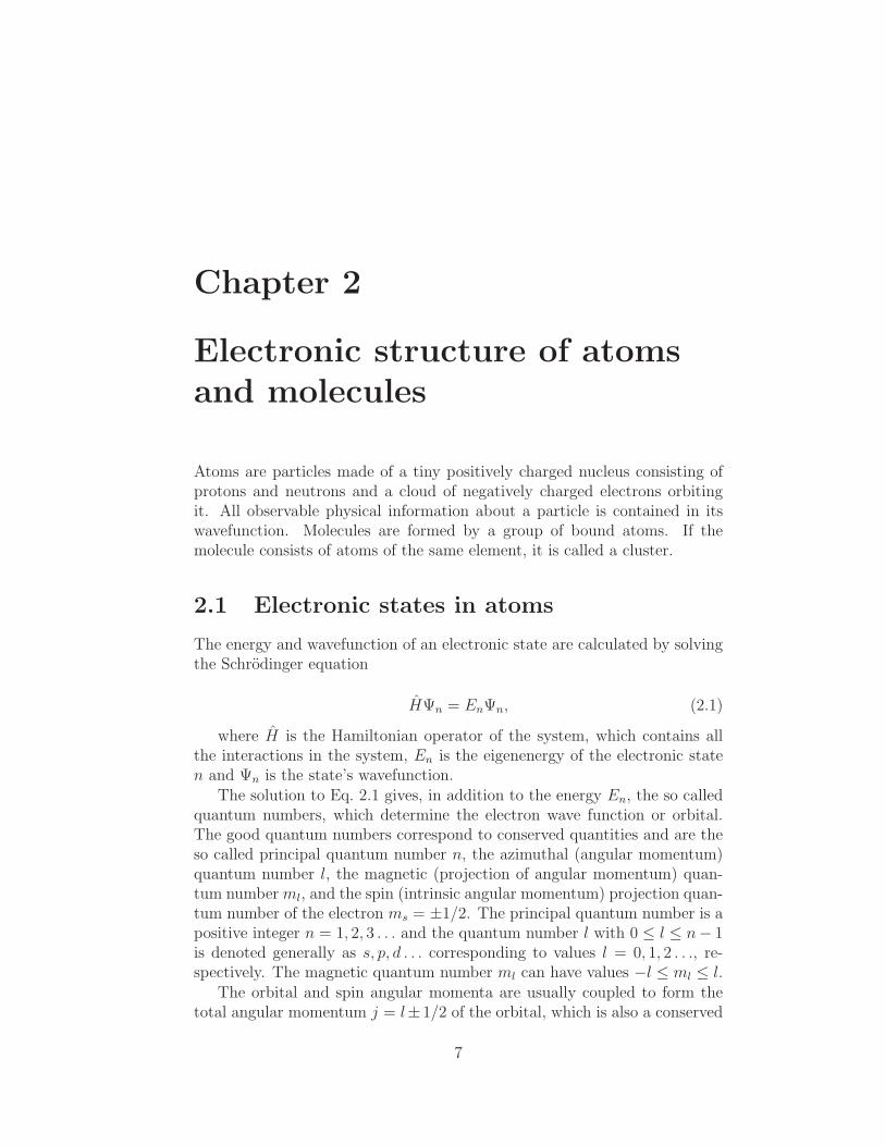
The nuclei of a molecule are never completely stationary and if enough energyis applied to a molecule in its ground state, the geometry – or internucleardistance – of the molecule can be distorted from the equilibrium position anda higher vibrational state can be occupied. This causes the nuclei to vibratewith respect to each other and the energy of the electrons is accordinglyaffected. The vibrational states are quantized and thus the occupied vibra-tional states are reflected as a discrete structure in a spectrum. A definedelectronic and vibrational state is referred to as a vibronic state. In similarfashion a transition in which both electronic and vibrational quantum num-bers are changed is called a vibronic transition. In Fig. 2.1 an illustration ofa set of potential energy curves for a diatomic KF molecule from Paper Vwith several vibronic sub states of the excited electronic state is presented.
9
Figure 2.1: Calculated potential energy curves for diatomic KF moleculewith vibronic states for the excited state (vertical lines) depicted in the insetfrom Paper V.
Jahn-Teller effect
The Jahn-Teller effect or Jahn-Teller theorem states that a non-linear moleculein a degenerate state cannot be stable. This can be interpreted so that ifa molecule is in a degenerate state, it will undergo geometrical distortion,which removes this degeneracy [21]. This distortion induces new vibrationalmodes in the molecule as well as level splitting in the electron spectrum andis observed for example in the valence photoionization of the Sb4 clusters inpapers III and IV.
2.3 Electron correlation
In a multielectron system the electrons do not only feel the potential ofthe nuclear particles, but also the presence of other electrons in the system.In order to be able to accurately predict the electronic structure of a giventarget and interpret the electron spectrum these so called electron correlationeffects need to be taken into account. This means that electronic states lyingclose in energy to each other and having the same properties can mix toform a new electronic state, which is no longer a pure state, but a linearcombination of the interacting states. This is the so called configurationinteraction (CI) effect and is one way of taking the electron correlation intoaccount in calculations. The effect of the correlation is seen in the electronspectra as a redistribution of intensity from one definite main spectral lineto several more widely distributed lines, called CI satellite lines [17].
10

In addition to CI the electron correlation is known to cause also so calledshake transitions, where ionization, excitation or electronic decay is accom-panied by an excitation or de-excitation of another electron, called shake-upand shake-down transitions, respectively. These shake transitions presentthemselves also as satellite transitions around the main lines, called shake-up (or -down) satellites [17].
11

12

Chapter 3
Transitions in atoms and
molecules
When an atom, a molecule or a cluster is subjected to an external pertur-bation, the electron cloud may rearrange itself and electrons can be lifted tohigher energy levels or emitted from the system. In this thesis mostly theionization and relaxation of a target after interacting with photons as wellas photo- and electron excitation processes are studied.
3.1 Photoionization
Photoionization is based on the photoelectric effect, where an electron isextracted from the target by a photon, whose energy is higher than thebinding energy of the electron. After the ionization the target is left in anionized – and possibly in an excited – state and the reaction formula becomes
A+ hν → A(∗)+ + e−. (3.1)
The excess energy of the photon, if no electronic excitations take placesimultaneously, is given to the electron as a kinetic energy
Ek = hν − Eb, (3.2)
where Ek is the kinetic energy of the emitted electron, hν the photonenergy and Eb the binding energy of the electron.
Angular distribution of photoelectrons
The angular distribution of photoelectrons can be described using the angularanisotropy parameter β. Within the dipole approximation (see Section 3.2)the differential cross section of electrons emitted at an angle θ with respectto the electric field vector of the incoming radiation can be presented as
13

dσ(hν)
dΩ=σ(hν)
4π[1 + βP2 (cos θ)] , (3.3)
where σ(E) is the total cross section of photoionization at photon energyE, and P2 is the second order Legendre polynomial.
The experiments in this thesis were performed at the so called magicdetection angle θ ≈ 54.7 in which P2 (cos θ) becomes 0 and any angulareffects can be neglected and the line intensities in the electron spectra reflectthe total photoionization cross sections of the transitions. Thus the relativeintensities of the lines can be compared without paying any attention to thefact that they might possess differing values of β.
3.2 Excitations
Photoexcitation
When the energy of the incoming photon is equal to the energy differencebetween an occupied orbital and a higher unoccupied bound orbital, thephoton is absorbed and the electron may be lifted (excited) to the higherorbital. The reaction formula becomes
A+ hν → A∗. (3.4)
The possible transitions are, in addition to the energy difference betweenthe states, determined by the selection rules, which can be obtained fromquantum mechanical examination of the transition probability of the excita-tion process from the initial state |ψi〉 to the final state |ψf〉
Wi→f ∝∣
∣
∣〈ψf | V |ψi〉∣
∣
∣
2. (3.5)
These rules can be physically interpreted as the conservation of angu-lar momenta. In the case of photoexcitation (and -ionization) the photon-electron interaction operator
V = eiωcn·rǫ · p, (3.6)
where ω is the angular frequency of the radiation, c is the speed of light,n is a unit vector pointing in the direction of propagation of the photon, ǫis a unit vector pointing in the direction of the photon polarization and p isthe momentum of the electron, becomes
V = ǫ · p, (3.7)
when the wavelength of the radiation is much larger than the size of theatom and the Eq. 3.6 can be approximated by the first term of its power
14

series representation. This is the so called dipole approximation and theselection rules for the transitions become
∆J = 0,±1,∆MJ = 0,±1 (3.8)
excluding transitions, where Ji = Jf = 0. Also for the parity (Π =
(−1)∑
li) the rule Πi 6= Πf must hold [17].
Electron excitation
Upon electron impact the incident electron is not absorbed, but carries awaypart of the energy and momentum following the impact. The possible pro-cesses are elastic scattering and inelastic scattering, and the latter is dis-cussed further. The inelastic scattering can be divided further into two kindsof processes: ionization and excitation.
In the first case the incident electron kicks out a bound electron from thetarget and the excess energy is shared by both the scattered and the emittedelectron. Thus no discrete peaks arise from the electron ionization as theenergy can be arbitrarily shared by the two. This process can be describedby the reaction formula
A+ e−0 → A∗+ + e∗−0 + e−. (3.9)
In the second case the incident electron gives a part of its energy andmomentum to the target electron and the target is left in an excited state.The reaction formula for this process becomes
A+ e−0 → A∗ + e∗−0 . (3.10)
The interaction operator in this case can be expressed as
V =Z∑
i=1
eiK·ri , (3.11)
where K is the momentum transfer of the incident electron to the tar-get [22].
Thermal excitation
In vapor phase samples, the temperatures are often sufficient to induce en-ergetic enough collisions for promoting the atom or molecule to a close lyinghigher electronic or vibrational state. The excitation takes place due to in-ternal collisions of the vapor and the population density of the ground andexcited states can be approximated by using the well known Boltzmann dis-tribution [23]
15

ρi =gie
−∆Ei/kT
∑
j
(
gje−∆Ej/kT) , (3.12)
where ∆Ei (∆Ej) is the energy difference of state i (j) from the groundstate and gi (gj) is the degeneracy of the state. This formalism has beenused to determine the thermal population of states when studying the vaporphase Si, Pb and KF in papers II,VI, and V.
Vibronic excitation
A vibronic state lying higher than the ground state can be excited throughmany processes. These possibilities are for example thermal excitation andphotoexcitation, where the thermal energy of a molecule is enough to promoteit to a higher vibronic state or where infrared photons are used to excite themolecule to a higher vibrational state, respectively.
A higher lying vibronic state can also be reached through photoexcitationto a higher electronic state or ionization, where the equilibrium positionsof the nuclei in the molecule in the excited electronic state are differentfrom the ground state positions as the electronic transitions take place ona much smalle time scale than the nuclear motion. Thus, according to theFranck-Condon principle, a transition from one vibrational energy level toanother during an electronic transition is more likely if the overlap of the twovibrational wave functions is larger [19].
3.3 Auger decay
When a target is left in an excited state, it will rearrange its electronicstructure in order to minimize the total energy of the system. The excessenergy must be propagated away from the system either via radiative decayor Auger decay. In radiative decay the excess energy is carried away bya photon and in Auger decay via electron emission. The Auger effect isdiscussed here in more detail as the probability of Auger decay of core holestates is much higher than the probability of radiative decay [24].
When removing a core electron from a system (or lifting it to a higherlying orbital), the system is left in a highly excited state, which minimizesits energy through a process, where an electron from a higher lying orbitalfills the core hole and another higher lying electron is ejected away from thesystem, carrying away the excess energy [17]. This so called normal Augerdecay process of an ionized sample can be expressed as
A∗+ → A++ + e−A, (3.13)
where e−A is the emitted Auger electron, whose kinetic energy becomes
16

EA = E∗+ − E++, (3.14)
where EA is the kinetic energy of the Auger electron, E∗+ is the totalenergy of the initial excited and ionized state and E++ is the total energyof the final doubly charged state. In the case of a resonant excitation thereaction formula becomes
A∗ → A+ + e−A, (3.15)
and the kinetic energy of the Auger electron
EA = E∗ − E+. (3.16)
In case of deep core holes it is possible that the target is left in an excitedstate even after the Auger decay and can further decay via the same mech-anism. This and possible further decays are called cascade Auger processesand are not discussed further in this work.
The Auger decay is mediated via the Coulomb interaction between theelectrons participating in the transition and the operator can be expressedas
V =1
rij, (3.17)
and thus the transition probability becomes
Wi→f ∝∣
∣
∣
∣
∣
⟨
ψf
∣
∣
∣
∣
∣
1
rij
∣
∣
∣
∣
∣
ψi
⟩∣
∣
∣
∣
∣
2
. (3.18)
From this the selection rules ∆L = ∆ML = ∆S = ∆MS = ∆J = ∆M =0 and Πi = Πf can be obtained in pure LS-coupling.
3.4 Lifetime of excited states
The transition rate and number of all possible electronic decay pathwaysdetermine the so called lifetime of the excited state. This lifetime causes,according to the Heisenberg uncertainty principle, an inherent energy broad-ening of spectral lines called the natural linewidth and can be presentedfollowing the uncertainty principle as
∆E = h/t, (3.19)
where t is the finite lifetime of the excited state and ∆E is the naturallifetime broadening of the transition. The probability of finding the systemin the excited state follows a Lorentzian distribution around the excitationenergy with ∆E as the full width at half maximum (FWHM) [17].
17

3.5 Fragmentation of molecules and clusters
In molecules and clusters the electronic decay pathways are not the only wayof energy release of the excited state. If the energy brought into the systemis sufficient, the target molecule or cluster may dissociate into smaller pieces.For the molecule to fragment into smaller species it is generally not necessaryto ionize the molecule, but in this thesis only ionic fragmentation has beenstudied and so discussion about fragmentation of neutral species has beenomitted. Studying the ionic fragments produced following photoionization orAuger decay provides information about the bonding properties of the MOsinvolved in the transitions.
Within this work two kinds of dissociation processes of singly and doublycharged Sb4 ions have been studied in papers III and IV. One is the socalled two-body dissociation, where the molecule or cluster breaks directlyeither into two charged pieces or into one charged and one neutral species.The other is a three-body dissociation, where the ion dissociates into threepieces.
In the case of a singly charged ion the two-body dissociation (TD) istrivial and the ion is fragmented into one singly charged species and anotherneutral species. When the initial ion is in a doubly charged state a TD leadsdirectly into two singly charged particles.
Three-body dissociation of a doubly charged ion is slightly more complexthan TD as in addition to two charged particles also a neutral particle isemitted. The dissociation can be further divided into three kinds of pro-cesses: deferred charge separation (DCS), secondary dissociation (SD), andconcerted dissociation (CD). In DCS the neutral particle is first emitted fol-lowed by a charge separation into two fragments. In SD the charge is firstseparated into two singly charged ions one of which emits a neutral particle.In CD all three fragments are created simultaneously.
Momentum correlation in dissociation of ionic molecules
In order to be able to distinguish between the different possible fragmentationpathways and to know at which stage the charge separation takes place, theion products need to be measured in coincidence and the momentum correla-tion between the ions needs to be determined. The experimental techniquesfor measuring the ions and their momentum correlation using ion time offlight spectroscopy will be presented in Chapters 8 and 9. Here the physicalanalysis for determining the pathway from the information obtained fromthis sort of experiments is briefly discussed.
When studying ion-ion coincidence events using the time of flight spec-troscopy, the momentum correlation between two fragments is observable inthe flight time spreads of the fragments in question as the laws of momentum
18

Figure 3.1: Sb+2 +Sb+
2 coincidence event following the NVV Auger decay ofSb4 clusters. The separate lines are due to different isotope combinations ofthe cluster. The slope of these events according to Eq. 3.21 is trivially −1.
conservation must be fulfilled: The momentum received in the dissociationreflects in shorter or longer flight time of the first ion, depending on its direc-tion, whereas the second fragment receives an equal amount of momentum,but in the opposite direction.
An example showing an Sb+2 +Sb+
2 ion-ion coincidence event following theNVV Auger decay of Sb4 studied in Paper III is presented in Fig. 3.1. Bystudying the slope of the coincidence event,
slope =∆T2∆T1
, (3.20)
where ∆T2 and ∆T1 are the flight time spreads (the difference betweenthe longest and the shortest observed flight times) of the heavier – or slower– and the lighter – or faster – fragments, respectively, information aboutthe momentum correlation can be obtained. It can be shown, using themomentum conservation law and simple equation of motion for the chargedparticles in the time of flight spectrometer, that for TD the slope becomessimply
∆T2∆T1
= −q1q2, (3.21)
19

where q1 and q2 are the charges of the faster and slower fragment, respec-tively.
When studying the three-body dissociations the situation is slightly morecomplicated. In the case of CD, where all fragments are emitted simultane-ously, no momentum correlation between the two ions exists as the thirdneutral particle is not detected. However, if the fragmentation follows theSD pathway, the fragmentation process can be presented as a reaction
M q1+q2 → M q11 +M q2
2
M q22 → M q2
2a +M02b, (3.22)
where M1 is always assumed to be the lighter fragment and M2 the heav-ier. If the energy release of the secondary process is small, some correlationbetween the first and second charged particle M1 and M2a is preserved. Andin the case that M2a is heavier than M1, the slope in a plot, where the y-axiscorresponds to the slower fragment flight time, becomes
slope =∆T2a∆T1
= −M2a
M2
q1q2. (3.23)
If M2a is lighter than the first ionic fragment M1, the slope then becomes
slope =∆T1∆T2a
= − M2
M2a
q2q1. (3.24)
In DCS the dissociation, where the charge separation takes place, is es-sentially a two-body process and thus the slope becomes
∆T1b∆T1a
= −q1aq1b, (3.25)
where ∆T1b is the flight time spread of the heavier ionic fragment, ∆T1athe flight time spread of the lighter ionic fragment, and q1a and q1b the chargesof the lighter and heavier ionic fragment, respectively.
Knowing these relations and determining the slope from the recorded ion-ion coincidence patterns, one can, in principle, determine experimentally theexact fragmentation pathway of the ionic molecule.
20

Chapter 4
Vapor production
The studied samples in this thesis are mainly vapors except for the test mea-surements on noble gases in Paper I. To produce these atomic, molecularor cluster vapors special oven setups are necessary [25]. For producing therelatively low temperature vapors Pb and KF (papers VI and V) a resistivelyheated Thermocoax oven built in Oulu [26] has been used. In this oven a re-sistively heated wire, wound in non-inductive manner, surrounds the crucibleand heats the crucible via thermal conduction and radiation. The setup issurrounded by special heat shields to minimize power losses to surroundings.The same oven has been used for producing the Sb4 vapor in the electronenergy loss experiments. In these experiments a stainless steel crucible wasused. In the coincidence experiments of Sb4 a resistively heated commercialMBE Komponenten model NTEZ-40 oven with an open pyrolytical boronnitride crucible was used.
For measuring atomic Si vapor a high temperature was necessary anda special inductively heated oven was used [27]. In short, the inductionoven consists of a heating coil surrounding the heated volume. As an RFAC current is applied to the coil, the changing induced magnetic field causeseddy currents in the conducting crucible and sample. These currents and thehysteresis losses of the magnetic field heat the crucible and the sample. Sincethe magnetic field disturbs the emitted electrons, the heating is operated ina pulsed mode and the spectra are recorded when the heating pulse is off.As the production of Si atoms requires extremely high temperatures a singleholed tungsten crucible was used. The same induction oven equipped with asingle holed molybdenum crucible was used for the production of Sb4 vaporin Paper IV, when recording the valence photoelectron spectrum at highertemperatures.
21

22
Chapter 5
Synchrotron radiation
Synchrotron radiation is electromagnetic radiation emitted from relativis-tic, accelerating charged particles in a synchrotron. The advantages of syn-chrotron radiation with respect to other light sources are its high brilliance,monochromaticity and wide tunability. The radiation can be emitted frombending magnets used to direct the beam on the round trajectory of the stor-age ring or from special insertion devices (undulators and wigglers) made forlight production. In this work light emitted from undulators is discussed andthe discussion about wigglers is omitted.
5.1 Electron storage rings
Electron storage rings are electron accelerators dedicated to the productionof synchrotron radiation. In storage synchrotrons the electrons are not onlyaccelerated to the desired energy, but the electron beam is stored in thering by compensating for the kinetic energy lost by the electrons during theradiation emission by using radio frequency (RF) acceleration voltage.
In short, the electrons are first accelerated to a high initial energy using,typically, a linear accelerator called the injector. The accelerated electronbeam is passed into the synchrotron, where it is kept on a closed circular(or semicircular) orbit by means of bending magnets. Between the bendingmagnets are a number of straight sections that can house insertion devices,electron beam focusing magnets or RF cavities. The focusing magnets areused to keep the cross section of the beam within desired limits, the insertiondevices are used to produce synchrotron radiation and the RF cavities toaccelerate the electron beam to the final energy and to regain the energy lostas synchrotron radiation. A schematic drawing of a synchrotron storage ringis presented in Fig. 5.1.
The electrons in a storage synchrotron travel in short bunches and therings can be run in single or multi bunch mode. In single bunch modeonly one bunch of electrons is traversing the synchrotron and radiation is
23

Figure 5.1: A schematic representation of a synchrotron electron storage ringfrom Ref. [29].
emitted in short well separated pulses. In multi bunch mode several bunchestraverse the ring simultaneously and the radiation emitted can be in mostexperimental cases thought to be continuous. The advantages of single bunchoperation are clear for example in the case of time-resolved or coincidencestudies, where the exact arrival time of the incoming photon beam needs tobe well known. In this study the synchrotrons used were operated in themulti bunch mode.
The radiation from the bending magnets and insertion devices is directedto the experiment via so called beamlines, which house all the necessary pre-and post focusing optics and monochromators. The beamlines used in theexperiments performed in this thesis are presented in Chapter 10.
5.2 Bending magnet radiation
Bending magnet radiation in an electron storage ring is emitted from elec-trons traversing on a circular path in a bending magnet. The centripetalacceleration of the electron causes it to radiate and the relativistic motioncauses the emitted radiation wavelengths to be shifted towards smaller wave-lengths due to the Doppler effect, when observed in the laboratory frame.
The spectrum of the radiation emitted from a bending magnet is contin-uous and can be characterized by the so called critical frequency [28]
ωc =3cγ3
2ρ, (5.1)
where γ = E/m0c2 is the Lorentz factor, c is the speed of light and ρ
24

is the radius of curvature of the electron path in the magnetic structure.Half of the radiated power is emitted at frequencies below ωc and half above.A typical bending magnet radiation spectrum is similar to the continuousspectrum of an X-ray tube.
The radiation is emitted into a very narrow opening angle 1/γ, whichresults in extremely high brilliance of synchrotron radiation. Another impor-tant property of synchrotron radiation is its polarization. When observed inthe plane of the electron trajectory, the radiation emitted from a bendingmagnet is linearly polarized. Observing above or below the plane will resultin elliptically polarized light with different helicities [28].
5.3 Undulator radiation
Undulator radiation is emitted from electrons travelling through a periodicalmagnetic structure called an undulator. The varying magnetic field in theundulator causes the electron to travel on a sinusoidal trajectory and thusradiation is emitted. In this work two kinds of undulators were used: aplanar undulator and an elliptically polarizing undulator. These two typesand their properties are discussed here briefly in more detail.
Planar undulators
The magnetic field of a planar undulator is typically
By = B0 cos kuz, (5.2)
where the period of the undulator is λu and ku = 2π/λu and the wave-length of the emitted undulator radiation becomes
λ =λu2γ2
(
1 +K2
2+ γ2θ2
)
, (5.3)
where θ is the observation angle and K the so called undulator parameter
K ≡ eB0λu2πmc
. (5.4)
Due to the small oscillatory motion of electrons, the undulator radiationis collimated to a very small opening angle θcen = 1/(γ
√N), where N is
the number of magnetic periods, and the spectrum consists of several highlyintense peaks, called harmonics. These harmonics are due to axial accel-eration of the electrons, which causes higher order effects in the radiationwavelengths [30]. Due to the coherent superposition of the radiation fromseparate magnetic structures the brilliance and flux are increased by a fac-tor of N2 and a discrete spectrum is observed. The width of a harmonic is
25

Figure 5.2: A schematic drawing of an APPLE II type EPU from [31].
determined by the natural width of the harmonic as well as the acceptanceangle of the radiation. The acceptance angle is typically made smaller byusing pinholes or baffles in front of the beam, but this is done at the costof intensity. The photon energy of the undulator radiation can be changedby tuning the magnetic field, i.e. by changing the distance (gap) betweenthe magnetic poles. The radiation of a planar undulator in the plane of thesynchrotron is linearly polarized [30].
Elliptically polarizing undulators
Elliptically polarizing undulators (EPU) are undulators that can producealso elliptically polarized light in addition to linear polarized light. There aremany different EPU designs with different characteristics and in this thesis,radiation from an APPLE II (Advanced Planar Polarized Light Emitter II)type EPU has been used.
An APPLE II type EPU can produce radiation with both horizontaland vertical linear polarization (parallel and perpendicular to the plane ofthe synchrotron, respectively) as well as both left- and right-handed circular(and elliptical) polarization. A schematic drawing of an APPLE II EPU ispresented in Fig. 5.2.
The change in the polarization state of the radiation is achieved by movingthe two diagonal magnet arrays backwards or forwards and keeping the othertwo in fixed position. This causes a change in the overall strength of thevertical and horizontal magnetic fields thus changing the trajectory of theelectron traversing the undulator. The total vertical and horizontal fieldstrengths can be obtained from the superposition of the fields generated byboth diagonal array pairs and become
Bx = −2Bx0sin
(
φ
2
)
cos
(
2πs
λu+φ
2
)
26

By = 2By0 cos
(
φ
2
)
sin
(
2πs
λu+φ
2
)
, (5.5)
where Bx0and By0 are the peak horizontal and vertical magnetic fields of
the magnetic arrays, φ is the so called phase difference of the diagonal arraypairs, s is the distance travelled by the electron inside the undulator, and λuis the period length of the undulator. The phase difference can be expressedas
φ =2πD
λu, (5.6)
where D is the shift between the two diagonal array pairs. From Eq. 5.5it can be seen that when φ = 0 only the vertical field component is non-zeroand horizontal linear polarized light is emitted. For φ = π (or D = λu/2)only the horizontal component is preserved and vertical linear polarized lightis emitted. Choosing φ between π and zero will produce elliptically polarizedlight and in order to produce circular polarized light, the electron needsto traverse in a circular helical path meaning that the two perpendicularmagnetic fields should be equal, resulting in a phase difference
φ = 2arctanBy0
Bx0
. (5.7)
Taking a phase shift beyond π or below 0 will result in the same elec-tron trajectories, but with opposite direction of rotation. This will result inpolarization with right or left handedness depending on the sign of φ.
27

28

Chapter 6
Experimental electron
spectroscopy
In experimental electron spectroscopy the sample is bombarded with particlessuch as electrons or photons and the electrons emitted from the target as aconsequence are detected and analyzed. In the work presented in this thesiselectron and photon bombardment have been used to perturb the systemunder study. Both photoelectrons and Auger electrons have been detectedand analyzed to provide information about the electronic structure of thetarget.
6.1 Electron energy analyzer
When electrons are in the presence of an electric field E and (or) a magneticfield B, they feel the Lorentz force
F = −e (E+ v ×B) , (6.1)
which deflects the trajectory of the electron depending on the magnitudeof the corresponding fields. This property can be used to separate electronswith different kinetic energies by applying an electric or a magnetic field.A common method for performing the energy separation is to use an elec-trostatic field electron energy analyzer, where the deflection of the electrontrajectory depends on the field strength, the geometry of the analyzer andthe kinetic energy of the electron. The electron energy analyzer used in thiswork was a modified electrostatic hemispherical Scienta SES–100 electronenergy analyzer mounted on a vacuum chamber built in Oulu [32, 33]. Thisexperimental setup is presented in Fig. 6.1. The setup used in this workdiffers from the one in Fig. 6.1 in that it uses a position sensitive resistiveanode detector (Qantar Model 3394A) with a Qantar Model 2401B PositionAnalyzer ADC unit instead of the fluorescent screen and CCD camera.
29

Figure 6.1: The Scienta SES–100 electron energy analyzer with a CCD cam-era and fluorescent screen setup.
The analyzer is operated in a constant pass energy (Ep) mode, where theelectrons are retarded / accelerated to a constant kinetic energy, which allowsthem to pass through the hemisphere. Electrons with different initial kineticenergies end up having slightly different final energies and are dispersed atthe detector plane of the analyzer and can thus be separated in energy withina certain bandwidth (∆E) around Ep. An electrostatic lens system is usedbefore the dispersive element to keep the source volume fixed and to allow aconstant magnification of the object when changing the retardation / accel-eration. The use of a constant pass energy offers a constant energy resolutionover the measured kinetic energy region as the resolution of a hemisphericalelectron analyzer is (neglecting angular effects)
∆E =w
2REp, (6.2)
where w is the width of the entrance slit and R is the radius of the orbit ofan electron having a kinetic energy equal to the pass energy of the deflector.In this work the resolutions are presented as full width at half maximum(FWHM).
30

6.2 Experimental linewidths
The observed linewidths for different transitions in electron spectra are de-pendent mainly on four or three factors in the case of photoelectrons andAuger electrons, respectively. For photoelectrons the dominating factors arethe bandwidth of the photons (∆Ehν), the resolution of the electron ana-lyzer (∆Ea) and the inherent natural linewidth of the transition in question(∆En) together with the Doppler broadening (∆ED). The total linewidth ofphotoelectrons then becomes a convolution of the constituents
∆Epetot = ∆Ehν ∗∆Ea ∗∆En ∗∆ED. (6.3)
For Auger electrons, within the two step model, the photon bandwidthdoes not play any role in the linewidth and the total broadening becomes
∆EAtot = ∆Ea ∗∆En ∗∆ED. (6.4)
The Doppler broadening is dependent on the kinetic energy of the elec-tron, temperature and mass of the sample and can be expressed as [34]
∆ED = 0.7215×√
Ek × T
M, (6.5)
where the broadening ∆ED is given in meV, Ek in eV, temperature T inkelvin, and the mass M in atomic mass units.
It is important to notice that whereas the two experimental contribu-tions and the Doppler broadening result in Gaussian lineshapes, the inherentnatural broadening gives a Lorentzian contribution. Thus the convolution(final lineshape) becomes a Voigt profile. The above mentioned applies fortransitions in atoms, and in molecules the lineshape is further complicatedby molecular field effects.
6.3 Calibrations
In order to obtain reliable information about the electron spectra severalcalibrations need to be performed. In case of electron spectroscopy, themost important calibrations are binding energy calibration, kinetic energycalibration and transmission correction.
Energy calibration
The energy calibrations in this work are generally performed using well knownbinding and kinetic energy values of photoelectrons and Auger electrons ofnoble gases, respectively [35]. The noble gases can be introduced into the
31

experimental chamber easily together with the vapor sample and measuredsimultaneously to calibrate the energy scale.
Transmission correction
The measurement of a complete Auger- or photoelectron spectrum usuallymeans covering a wide range of kinetic energies. In general the transmissionof an electron analyzer is not constant over the whole kinetic energy regionand this varying transmission causes changes in the relative intensities ofthe observed peaks. For obtaining the correct relative intensities a specialtransmission correction procedure is used. In this procedure the transmis-sion is determined by measuring the ratio of intensities of a photoelectronline and the corresponding Auger lines: As the total intensity of all Augerlines should be equal to the intensity of the photolines, when the radiativedecay channel is negligible, and the kinetic energies of the Auger lines re-main constant resulting in constant transmission, the varying transmissionis reflected only in the intensity of the photoelectron lines. Thus by mea-suring the photoelectron spectrum at varying photon energies together withthe Auger electron spectrum, the transmission function can be obtained bycomparing the intensity ratios. The procedure is described in more detail inRef. [36].
32

Chapter 7
Electron energy loss
spectroscopy
7.1 Basic principle
In electron energy loss spectroscopy (EELS) the sample is bombarded withmonoenergetic electrons. The electrons scatter both elastically and inelasti-cally from the target, and the inelastically scattered electrons lose energy dueto the electronic excitations taking place in the target atom caused by thecollision. In EELS the inelastically scattered electrons are detected and theloss of their energy is measured. The technique has been used in studyingseveral types of samples from atoms to molecules and clusters [37, 38, 40, 41].
The transitions in the target take place due to the momentum transferfrom the incident electron to the target, which can be expressed as
K = k0 − k1, (7.1)
where k0 is the momentum of the electron before the collision and k1 isthe momentum after the collision. Here the momentum of the target can beneglected due to its much larger mass. Furthermore one can write
K2 = |k0|2 + |k1|2 − 2 |k0| |k1| cos θ, (7.2)
where θ is the scattering angle of the incident electron [41] with respectto the original direction of the electrons. Now the interaction operator canbe expressed in a similar form to the one in photon interaction and becomeseiK·r, where K is the momentum transfer from Eq. 7.1. Thus the transi-tion probability between states |ψi〉 and |ψf〉 is proportional to the matrixelement [22]
Wi→f ∝∣
∣
∣
∣
∣
∣
〈ψf |Z∑
j=1
eiK·rj |ψi〉∣
∣
∣
∣
∣
∣
2
, (7.3)
33
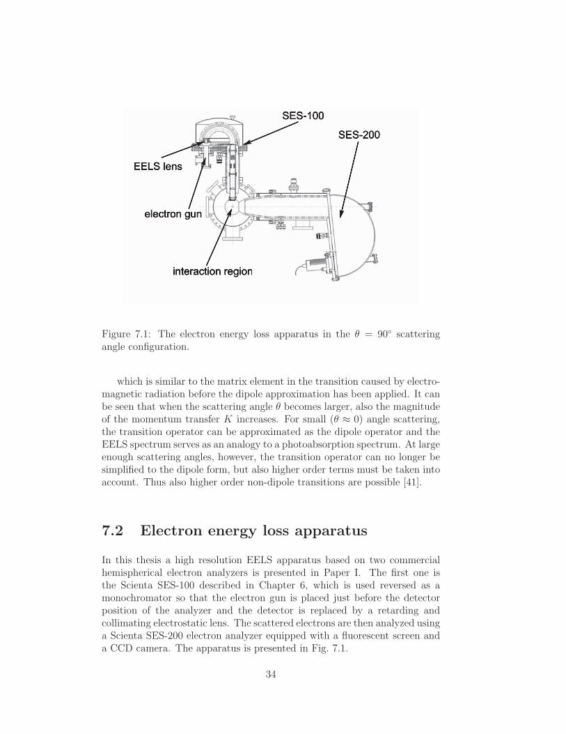
Figure 7.1: The electron energy loss apparatus in the θ = 90 scatteringangle configuration.
which is similar to the matrix element in the transition caused by electro-magnetic radiation before the dipole approximation has been applied. It canbe seen that when the scattering angle θ becomes larger, also the magnitudeof the momentum transfer K increases. For small (θ ≈ 0) angle scattering,the transition operator can be approximated as the dipole operator and theEELS spectrum serves as an analogy to a photoabsorption spectrum. At largeenough scattering angles, however, the transition operator can no longer besimplified to the dipole form, but also higher order terms must be taken intoaccount. Thus also higher order non-dipole transitions are possible [41].
7.2 Electron energy loss apparatus
In this thesis a high resolution EELS apparatus based on two commercialhemispherical electron analyzers is presented in Paper I. The first one isthe Scienta SES-100 described in Chapter 6, which is used reversed as amonochromator so that the electron gun is placed just before the detectorposition of the analyzer and the detector is replaced by a retarding andcollimating electrostatic lens. The scattered electrons are then analyzed usinga Scienta SES-200 electron analyzer equipped with a fluorescent screen anda CCD camera. The apparatus is presented in Fig. 7.1.
34
7.3 Linewidths in electron energy loss spec-
troscopy
In EELS the widths of the spectral lines are determined by the two exper-imental Gaussian profiles of both the electron monochromator (∆Em), theelectron analyzer (∆Ea) and the Doppler broadening (∆ED) together withthe inherent Lorentzian profile of the transition under study (∆En) [42] andbecomes
∆Etot = ∆Em ∗∆Ea ∗∆ED ∗∆En. (7.4)
Thus to obtain high resolution EELS spectra, both the monochromatorand the analyzer need to achieve high resolution.
35

36

Chapter 8
Ion spectroscopy
In ion spectroscopy the ions produced in the ionization process are collectedand their mass and charge are recorded. In this work the ion time of flight(TOF) method is used for ion detection. In short, a TOF spectrometer usesa pulsed electric field to extract the ions from interaction region and startthe flight time measurement. Ions with different charge to mass ratio willarrive at the detector at separate times producing a mass spectrum of thesample.
8.1 Ion time of flight spectroscopy
In the work performed in this thesis a Wiley-McLaren type ion TOF spec-trometer was used [43]. The ions are created in the excitation region of theanalyzer. After the ion creation a positive extraction pulse is applied. Thepulse serves several purposes: it starts the time measurement of the ions andremoves the ions from the ionization region. After this the ions enter theacceleration region, where a constant accelerating electric field is present atall times. From the acceleration region the ions pass to a field free region orthe drift region after which they reach the detector and the detection timewith respect to the starting pulse is recorded. The flight time of the ions ina TOF spectrometer is
T = A
√
M
Q+ T0, (8.1)
where M and Q are the mass and charge of the ion, respectively, and Aand T0 are constants depending on the geometry of the analyzer and the elec-tric fields applied. This simple relation with only two unknown coefficientsallows accurate calibration and conversion of the acquired flight time spec-trum to a mass/charge scale by using two well known calibration lines in thespectrum. Typically residual gases such as H2O, N2 or O2, that are nearlyalways present in a vacuum system to some extent, are used for calibration.
37

8.2 Total ion yield
In a total ion yield (TIY) measurement all the ions produced in the ionizationprocess are collected and no mass analysis is carried out. This can be donesimply by applying a constant extraction voltage for the ions and countingthe number of ions per unit time.
Total ion yield in absorption measurements
In this thesis the TIY method has been used in the absorption measurementsas a part of the characterization of the FINEST beamline branch (see Chap-ter 10) and in the ultra-high resolution absorption study of the KF moleculeperformed in Paper V. The TIY absorption spectrum can be recorded byscanning the exciting photon energy in small steps and recording the ionyield at each stage. In the presence of an autoionizing resonance the ion pro-duction is enhanced and is observed as a strong peak in the TIY spectrum.The TIY method does not, however, always reflect the actual cross-sectionof the resonance as the radiative decay is not taken into account and is thusnot a complete analog to real absorption measurements.
Linewidths in total ion yield spectra
The TIY method is an excellent option for absorption measurements sinceit has basically no instrumental broadening caused by the ion detection.This leaves only the contributions from photon energy bandwidth, naturallifetime broadening of the excited state and the Doppler broadening of thegaseous sample. Thus the TIY method is excellent in for example photonenergy resolution studies, when the lifetime broadening of the excited statesis negligible. This has been employed in the resolution studies of the FINESTbeamline branch.
38

Chapter 9
Coincidence techniques
9.1 Electron-ion coincicdence
In electron-ion coincidence the detection of an electron starts the timing mea-surement of ions. The technique is based on the fact that the fast electronsare detected before the ions created in the same process have left the in-teraction region. This allows the detection of ions in coincidence with theelectrons meaning that they share a certain correlation: the process in whichthey were created.
Using the electron-ion coincidence technique it is possible to study thefragmentation pathways of a molecule following a chosen electronic transi-tion. It can also be used reversed as a mass selecting tool as certain linesin the electron spectrum can be associated with ions with different masses.This in turn helps in the analysis of the electron spectra. In addition whenthe bonding properties of given MOs are well known and the electron spec-trum is measured in coincidence with the fragmentation products one canmake a qualitative assignment of otherwise overlapping spectral features ifdifferent ions are produced in different regions of the spectrum [44, 45]. Thecoincidence technique has proven useful in studies of various types of targets(see e.g. [46, 47, 48, 49, 50, 51]).
In this thesis both photoelectron-photoion coincidence (PEPICO) andAuger-electron-ion-coincidence techniques have been used to study the frag-mentation of Sb4 clusters following valence and core ionization in papers IIIand IV.
9.2 Ion-ion coincidence
As the measurement time window for ion detection is typically a few tensof microseconds long, it is likely that more than one ion is detected withinone measurement. These ions are correlated if they originate from same
39

dissociation process (see Section 3.5). In this thesis the studied ion-ion-coincidences are electron triggered so called photoelectron-photoion-photoioncoincidences (PEPIPICO) and Auger-electron-ion-ion coincidences.
9.3 Electron-ion-ion coincidence apparatus
The electron-ion-ion coincidence apparatus used in the studies presented inthis thesis is based on the combination of the modified Scienta SES-100hemispherical electron energy analyzer and a Wiley-McLaren type of ionTOF spectrometer. The apparatus is operated in the pulsed extraction fieldmode, where the ion extraction pulses are either triggered by electrons de-tected by the SES-100 or randomly by a pulse generator. The apparatus ispresented in detail in Ref. [52].
9.4 Data handling
Detecting ions in coincidence with electrons is not a trivial experiment as therecorded data receives a large contribution from random coincidences, wherethe recorded ionic fragments do not come from the molecule from which theelectron was emitted. This can be explained by the difference in detectionefficiencies of the electron analyzer and the ion detector: the acceptance angleof the electron detector is typically in the order of 0.001 · 4π, whereas theion detector has typically an acceptance angle of approximately 4π. As theions are much slower to leave the interaction region than the electrons, thechances are that also ions not related to the observed electron are detected.These are called random ions, whereas the ions with real correlation to theelectron are called true ions [53].
As the recorded signal always has a contribution of random ions it isnecessary to subtract the random signal in order to obtain the pure true ionsignal. This however can be done only statistically and all data handling andresults are based on average values. To subtract the random ions, randomstart triggers are presented during the experiment and the corresponding ionsare measured. As the electron triggered coincidence events consist of bothtrue and random ions, whereas the random triggered events consist only ofrandom ions, the average amount of true coincidences can be obtained froma set of data with careful data analysis as
N true = N co − N rnd, (9.1)
where N true is the average number of true coincidences, N co is the averagenumber of electron triggered coincidences and N rnd is the average numberof random coincidences [52]. The statistical analysis and data handling in
40

this thesis were performed by a set of macros written for Igor Pro by Prof.Edwin Kukk.
To obtain the experimental information from the prepared data, partialion yield (PIY) curves as a function of electron energy are usually plottedand analyzed. For creating a PIY curve an ion with a certain flight time isselected and its yield as a function of the electron energy is determined fromthe experimental data. This data is generally visualised as a two dimensionalmap with the ion flight time on one axis and the electron energy on theother to allow easier analysis of possible fragmentation pathways. The datatreatment for ion-ion coincidence data was performed in a similar fashion.
The slope analysis of the ion-ion coincidence data was performed by acoordinate system transformation. First the two flight time axes were ro-tated and then the coincidence pattern was projected onto the x axis. Theprojection was fitted using a Gaussian function and the slope was calculatedfrom the rotation angle that gave the narrowest projection, assuming that inthis case the coincidence pattern was vertically oriented and the flight timespread due to correlated two-ion Coulomb explosion was eliminated. Theerror limits in the slopes were determined from the error limits of the fit.
41

42

Chapter 10
Beamlines
The experiments in the papers II, III, and IV were performed on the beamlineI411 at the 1.5 GeV MAX II electron storage ring and the experiments in thepapers V and VI were performed on the Finnish-Estonian FINEST branchline on the I3 beamline at the 700 MeV MAX III electron storage ring [54]. Abrief description of the I411 beamline and a more detailed discussion aboutthe I3 beamline and the FINEST branch line are presented in this chapter.
10.1 I411
Beamline I411 is a soft X-ray undulator beamline covering the photon energyrange from 50 eV to approximately 1500 eV and is designed for experimentson solid, liquid and gaseous samples. The source of radiation on the I411 is a2.65 m long undulator with a period length of 58.85 mm, 88 poles andKmax =3.6 [55]. The radiation from the undulator is first focused in the horizontaldirection by a cylindrical mirror and then monochromatized with a modifiedSX700 plane-grating monochromator, which uses a plane elliptical mirrorafter the grating for focusing the beam in the vertical direction. Both thehorizontal and vertical foci are located at the exit slit of the monochromatorand the light is refocused after the exit slit to the permanent end stationusing a single toroidal mirror [56, 57].
This setup provides a resolving power of 13000 at the photon energy of65 eV and 5700 at the photon energy of 400 eV [57]. The photon flux isin the order of 1011 − 1013 photons/s/100 mA in energies up to 800 eV inthe first and third harmonics of the undulator and first diffraction order ofthe monochromator. The spot size at the main end station is horizontally0.5 mm (full width at half maximum, FWHM) and vertically exit slit widthdependent.
The beamline is equipped with a differential pumping setup being capableof offering five orders of magnitude pressure isolation without the use of any
43

windows, a crucial feature for allowing high pressure vapor phase experimentswithout affecting the ultra-high vacuum in the rest of the beamline.
The beamline houses a permanent SES R4000 electron energy analyzerend station intended for electron spectroscopical studies of solids, liquidsand gases as well as vapor phase samples such as atomic metal vapors andclusters. In addition a one meter long part (the so called ’1–meter section’)of the beamline directly after the differential pumping stage and before themain end station is removable. This allows the users to mount their ownexperimental setups to the beamline. In the works presented in this thesisthe 1–meter section is used in all experiments performed on I411. The spotsize at the 1–meter section is slightly larger than at the R4000 with thehorizontal size being approximately the same, but the vertical size aroundtwo times larger [57].
10.2 FINEST branch line
The FINEST branch line is a beamline branch operating in the vacuumultraviolet (VUV) spectral range of the electromagnetic spectrum designedespecially for experiments on vapor phase samples. The FINEST branchwas designed and built by Finnish-Estonian consortium consisting of theUniversities of Oulu and Turku in Finland and University of Tartu in Estonia.This work consisted of performing necessary analysis, simulation and designof the refocusing optics as well as for the differential pumping stage.
I3
Undulator
The source of radiation of the I3 beamline is an EPU of APPLE II typemanufactured by the Advanced Design Consulting, Inc. The EPU has aperiod of 69.1 mm and total length of 1.962 m. The peak magnetic fieldsare By0 = 0.9088 T and Bx0
= 0.688558 T. The minimum gap is 16 mmcorresponding to Kmax
x = 4.44262 and Kmaxy = 5.86364.
Monochromator
The radiation from the EPU is monochromatized using a 6.65 m off-planeEagle type normal incidence monochromator (NIM) with vertical dispersion.The zero order focal distance of the grating is 6.65 m and the horizontalangle between the incident and reflected beam is approximately 1.5. For anoff-plane Eagle type NIM the grating equation becomes
44

Table 10.1: The parameters for the currently mounted gratings.
Grating Coating Ruling [l/mm] Energy range [eV]G1 Al/MgF2 2400 4–11G2 SiC 4300 8–25G3 Pt 4300 25–50
mλn =2 sin θ
√
1 + z2
R2 cos2 θ
, (10.1)
where m is the diffraction order, n is the number of grooves (1/mm),θ is the diffraction angle, R the radius of the spherical grating and 2z thedistance between the entrance and exit slit [58, 59]. Now the focus of thegrating is located on the Rowland circle and the focal distance (from gratingcenter in the direction of the zero order normal of the grating) becomes
l = R cos θ. (10.2)
In order to keep the focus of the diffracted photon beam on the exit slit themonochromator needs to be moved towards the slits by 1 − l = 1 − R cos θin addition to rotating the grating. This causes a small deviation in thehorizontal position of the beam at the target due to the long exit arm, butis compensated using a mirror described in the following chapter.
The monochromator of the I3 beamline is manufactured by Bestec GmbH[60] and can be fitted with five different gratings that can be changed invacuum. Presently three gratings are installed. The parameters for thesegratings are given in Table 10.1. The energy regions given in Table 10.1 arethe ones where the grating efficiency is optimal.
Optics
A schematic drawing of the optical configuration of the beamline I3 up tothe FINEST branch line is presented in Fig. 10.2.
After being emitted from the undulator, the radiation hits the first opticalelement M1, a water-cooled spherical mirror (SM) that focuses the divergingphoton beam to the monochromator grating G and creates a virtual imageof the source further upstream from the original source. The second opticalelement after M1 is a plane mirror (PM) M2 for directing the beam upwards.After M2 the radiation is diverted back parallel to the plane of the syn-chrotron and focused vertically to the entrance slit of the monochromatorby a plane elliptical mirror (PEM) M3. The fact that the vertical virtualsource of M3 is now located further upstream from the original source gives
45

Figure 10.1: A schematic view of the FINEST beamline optics. The relativedistances are presented in a logarithmic scale.
an advantage in the demagnification factor of M3 as the entrance arm iselongated.
From the monochromator entrance slit the light is further passed on to thespherical grating G, which again focuses the beam vertically to the exit slitof the monochromator. After the monochromator the beam hits a verticallyoriented plane mirror M4, which is used to compensate for the horizontaldisplacement of the beam caused by the movement of the grating necessaryto keep the focus at the exit slit when changing the photon energy. Thisrotation of M4 also opens up the possibility of having several branches onthe beamline and is used for flipping the beam between the branches. Inorder to divert the beam to the FINEST branch line, the angle of incidenceof M4 is increased by approximately 1.2. This flips the beam to M5, whereasin the solid-state branch operation the beam passes past M5 (see Fig. 10.2).
After emerging from the M4 in the FINEST branch operation, the beampasses to a single toroidal refocusing mirror (TM) M5 used to focus the beamto the target position. A single TM was chosen as the refocusing optics dueto space limitations.
In this configuration the vertical source of M5 is located at the exit slit ofthe monochromator, and the horizontal source is located further upstream atG whereas the horizontal and vertical foci are located at the same position1.9 m downstream from M5. This causes the vertical beam to be magnifiedby a factor of 1.5 as the vertical exit arm is longer than the entrance arm(see Table 10.2). The horizontal beam however is demagnified by a factor ofapproximately 0.25. The exit arm length is limited to a minimum of 1.9 mdue to the fact that it is necessary to have an efficient differential pumpingstage to allow high pressure vapor phase experiments.
The optical parameters of the various optical elements are given in Ta-ble 10.2.
46

Table 10.2: Optical parameters of the I3 beamline optics. Angles α and βare measured as incidence angles. Distances are presented with respect tothe zero order position of the grating. All elements are manufactured fromSi.M1 (SM) R = 20.8 m
Entrance arm: 5.6 mExit arm horizontal: 9.75 mExit arm vertical: -6.86 mα = β = 70
M2 (PM) α = β = 85
M3 (PEM) a = 4.98207 mb = 0.214449 mEntrance arm vertical (virtual): 9.31 mExit arm: 0.65 mα = β = 85
G (SG) R = 6.65 m 4200 l/mm, Ptα = β = 0.77 4200 l/mm, SiCEntrance arm vertical: 6.65 m 2400 l/mm, Al/MgF2
Exit arm vertical: 6.65 m
M4 (PM) α = β = 87.5
M5 (TM) R = 8.917 m Au coatingr = 0.5203 mEntrance arm vertical: 1.267 mEntrance arm horizontal: 7.917 mExit arm: 1.9 mα = β = 70
47
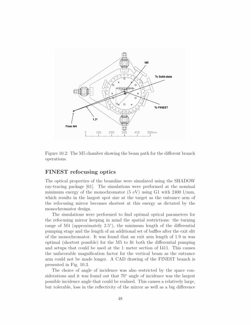
Figure 10.2: The M5 chamber showing the beam path for the different branchoperations.
FINEST refocusing optics
The optical properties of the beamline were simulated using the SHADOWray-tracing package [61]. The simulations were performed at the nominalminimum energy of the monochromator (5 eV) using G1 with 2400 l/mm,which results in the largest spot size at the target as the entrance arm ofthe refocusing mirror becomes shortest at this energy as dictated by themonochromator design.
The simulations were performed to find optimal optical parameters forthe refocusing mirror keeping in mind the spatial restrictions: the turningrange of M4 (approximately 2.5), the minimum length of the differentialpumping stage and the length of an additional set of baffles after the exit slitof the monochromator. It was found that an exit arm length of 1.9 m wasoptimal (shortest possible) for the M5 to fit both the differential pumpingand setups that could be used at the 1–meter section of I411. This causesthe unfavorable magnification factor for the vertical beam as the entrancearm could not be made longer. A CAD drawing of the FINEST branch ispresented in Fig. 10.3.
The choice of angle of incidence was also restricted by the space con-siderations and it was found out that 70 angle of incidence was the largestpossible incidence angle that could be realised. This causes a relatively large,but tolerable, loss in the reflectivity of the mirror as well as a big difference
48

Figure 10.3: A CAD drawing of the FINEST branchline.
between the reflectivites of the S- and P-polarized components of the incidentbeam. Gold (Au) coating was chosen in order to optimize the reflectivity athigh photon energies. The reflectivity of M5 was studied using the IMD pro-gram package [62]. The calculated reflectivity of M5 as a function of photonenergy is presented in Fig. 10.4.
The ray-tracing simulations using the optical parameters defined in Ta-ble 10.2 result in a spot size (4σ) of 660 µm (horizontal) and 620 µm (vertical)with a monochromator exit slit opening of 300 µm. An image of the spotfrom SHADOW simulations is presented in Fig. 10.5. The difference betweenthe analytical magnification of the exit slit by a factor of 1.5 to 450 µm andthe simulated value of 620 µm can be explained by the imaging errors thatoccur in real non-ideal optics, especially in the case of a toroidal mirror.
Differential pumping
A highly efficient differential pumping stage is necessary to allow high gasor vapor pressures within the target volume. For this a XIA DP–03 [63]differential ion pump with the so called ”line of sight pumping” capability waschosen. In total the differential pumping consists of three stages: the inputstage is a 200 l/s turbo molecular pump, second state the XIA DP–03, and thethird (output) stage a 100 l/s ion pump. In addition to the efficient pressureisolation, the ”line of sight pumping” allows efficient elimination of atoms andmolecules travelling towards the beamline parallel to the photon beam. Thisis important for minimizing the possibility of mirror contamination whenstudying various vapors.
The input and output aperture sizes of the DP–03 were limited by thesynchrotron beam size at the respective locations. The sizes were optimized
49

Figure 10.4: Calculated reflectivity of the Au coated toroidal refocusing mir-ror M5 as a function of photon energy at an incidence angle of 70.
Figure 10.5: The spot at target from the ray-tracing simulations.
50
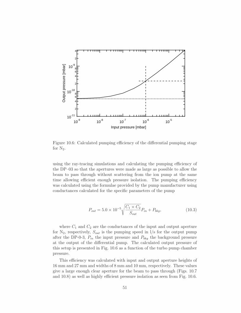
10-11
2
4
6
810
-10
2
4
6
810
-9
2
4
Ou
tpu
t p
ressu
re [
mb
ar]
10-9
10-8
10-7
10-6
10-5
Input pressure [mbar]
Figure 10.6: Calculated pumping efficiency of the differential pumping stagefor N2.
using the ray-tracing simulations and calculating the pumping efficiency ofthe DP–03 so that the apertures were made as large as possible to allow thebeam to pass through without scattering from the ion pump at the sametime allowing efficient enough pressure isolation. The pumping efficiencywas calculated using the formulae provided by the pump manufacturer usingconductances calculated for the specific parameters of the pump
Pout = 5.0× 10⁻⁵
√
C1 × C2
Sout
Pin + Pbkg, (10.3)
where C1 and C2 are the conductances of the input and output aperturefor N2, respectively, Sout is the pumping speed in l/s for the output pumpafter the DP-0-3, Pin the input pressure and Pbkg the background pressureat the output of the differential pump. The calculated output pressure ofthis setup is presented in Fig. 10.6 as a function of the turbo pump chamberpressure.
This efficiency was calculated with input and output aperture heights of16 mm and 27 mm and widths of 8 mm and 10 mm, respectively. These valuesgive a large enough clear aperture for the beam to pass through (Figs. 10.7and 10.8) as well as highly efficient pressure isolation as seen from Fig. 10.6.
51

-15 -10 -5 0 5 10 15
Horizontal [mm]
-15
-10
-5
0
5
10
15V
ert
ica
l [m
m]
Figure 10.7: Beam size at the output aperture of the DP–03. The box showsthe aperture size.
-10
-5
0
5
10
Ve
rtic
al [m
m]
-10 -5 0 5 10Horizontal [mm]
Figure 10.8: Beam size at the input aperture of the DP–03. The box showsthe aperture size.
52

Performance
During the commencing of the I3 beamline, the performance of the beamlinewas studied at the FINEST branch line. These characterization measure-ments included the measurement of the resolving power, photon energy cal-ibration, determination of the degree of linear polarization of the radiation,and photon flux measurements.
Resolving power
One of the acceptance requirements for the monochromator was that it shouldprovide a resolving power of at least 100000 throughout the photon energyregion as limited by the slit width of 5 µm and accuracy of the grating pitchangle of 0.5 µrad. In order to test whether this requirement is fulfilled and tosee the limits of the energy resolution of the beamline, the TIY technique formeasuring the absorption spectra of neon and argon between the 2p1/2 and2p3/2 ionization thresholds and 3p1/2 and 3p3/2 ionization thresholds, respec-tively, was applied. The autoionizing excitations taking place in the valenceshell of the Ne and Ar atoms have a relatively long lifetime corresponding toextremly small or negligible lifetime broadening of the spectral lines. Thusthe resolving power can be obtained from the width of the measured linescorresponding to transitions, where the lifetime of the state is well known.
The measured TIY spectrum of Ar is presented in Fig. 10.9, which showsan overview of the absorption spectrum up to the 3p1/2 ionization thresholdand the inset of the figure shows the 13s′ autoionizing line in detail measuredusing the grating G2 with slit opening of 5 µm with a gaussian width of115 µeV corresponding to a resolving power of roughly R = E/∆E = 138000at the photon energy 15.8358 eV. In Fig. 10.10 the Ne autoionizing line ispresented showing a gaussian width of 178 µeV at the photon energy of21.6125 eV corresponding to a resolving power of R = 121000. This spectrumwas recorded using the grating G3 and slit opening of 5 µm. Based onthese experiments, the monochromator performance exceeds the minimumrequirements and is highly competitive with other similar beamlines in use(see for example Refs. [64, 65]). The resolution as a function of the entranceand exit slit opening was also studied at these two resonances and the resultsare presented in Fig. 10.11.
Photon flux
In addittion to the energy resolution of the beamline, also the photon fluxthroughout the photon energy region covered by the NIM was recorded. Themeasurements were performed using an IRD Inc. AXUV100 photodiode, thequantum efficiency of which is known [66]. The known quantum efficiencyallows the calculation of number of photons incident on the photodiode per
53

Figure 10.9: An overview of the total ion yield spectrum of Ar between the3p1/2 and 3p3/2 ionization thresholds measured at FINEST. The inset showsthe 13s′ autoionizing line in detail measured with slit opening of 5 µm.
Figure 10.10: The autoionizing line of Ne in detail.
54

Figure 10.11: The resolution of the beamline as a function of slit opening attwo photon energies. The lines are drawn to guide the eye.
second from the current flowing in the circuit. The obtained flux curves forthe different gratings are presented in Figs. 10.12 and 10.13. Currently thering is filled up to approximately 250 mA, which corresponds to peak photonflux in the 1012 photons/sec region. The interesting oscillatory behaviorof the flux curve at high photon energies using G2 could be explained bythe coating thickness: thin coating causes interference effects between thereflections from the substrate and the coating material. This sort of behaviorwas observed in reflectivity simulations performed on 50 nm SiC coating onSi substrate with the IMD package and correspond very well to the observedflux curve.
Degree of linear polarization
The degree of linear polarization of the light on the FINEST branch wasdetermined following the discussion in Ref. [67] by measuring the angulardistribution of Xe 5p and Ne 2p photoelectrons at the photon energy of27.5 eV, having well known angular anisotropy parameters β = 1.9 andβ = 0, respectively (see e.g. Refs. [68, 69] and references therein). The valueP = (99± 2)% was obtained for the degree of linear polarization for verticallinear polarization.
55

Figure 10.12: Flux curves for gratings G2 and G3. The values have beencalibrated with the quantum efficiency and normalized to 100 mA ring cur-rent. The triangles present the data for grating G3 with horziontal linearpolarization and the squares for G3 with vertical linear polarization. Thecircles present the data for the grating G2 with vertical linear polarization.The difference in reflectivity of M5 for the different polarizations is clearlyvisible.
56

Figure 10.13: Flux curve for grating G1. The values have been calibratedwith the quantum efficiency and normalized to 100 mA ring current. Thedata is collected with vertical linear polarization.
57

58
Chapter 11
Summary of included papers
11.1 Electron energy loss apparatus for vapor
phase studies
In Paper I an electron energy loss apparatus for vapor phase studies is pre-sented. The design is based on using two commercial hemispherical electronanalyzers with a Scienta SES-100 acting as a monochromator and ScientaSES-200 as an electron analyzer. A special lens setup for focusing, collimat-ing and retarding the electron beam from the electron gun to the monochro-mator was simulated and constructed. The simulation results are presentedin Paper I. In addition, high resolution EELS spectra of noble gases Xeand Kr were measured at the 0 and 90 scattering angles corresponding todipole and non-dipole transitions, respectively. The apparatus was provento work well and gave good results for the noble gases. In addition, usingthis apparatus, the valence EELS spectrum of Sb4 vapor was recorded andis presented in Section 11.4.
11.2 Inner-shell photoioniziation of atomic Si
and Pb
The study of inner-shell photoionization and subsequent Auger decay of open-shell atoms has remained an important and interesting, but a relatively un-touched subject in atomic physics research for years. Whitfield et al. [70]have attributed this to the difficulty of producing atomic open-shell samplesas compared to experimentally easy rare gases. Most of the open-shell ele-ments are solid in standard conditions and thus special heating techniquesfor atomic vapor production are necessary as discussed in Chapter 4. Inaddition especially vapors tend to contaminate the experimental chamberand the elements of the electron analyzer causing charging effects and short
59

circuits. However, despite the difficulties, it is important to study experi-mentally the electronic structure of open-shell atom vapors as the only wayof testing, which theoretical methods are applicable in describing the elec-tron dynamics of these atoms, which differ notably from their closed-shellcounterparts [71].
The elements Si and Pb are both commonly used in the production ofsemiconductor devices as well as in other industrial processes. Althoughpresenting the same type of valence electronic configuration (Si: [Ne]3s23p2,Pb:[Xe]4f 145d106s26p2), Si in its solid form is a semiconductor, where as Pbis conducting. As the size of the devices is rapidly decreasing towards thequantum mechanical limit and the manufacturing of nanosized devices ison the horizon, information about the electronic properties of small metaland semiconductor clusters is extremely important. However, to understandthe properties of the clusters, first the properties of the atoms need to beunderstood in detail as well [72]. In this thesis the inner-shell photoionizationand the subsequent Auger decay of atomic Si and Pb have been studiedexperimentally using synchrotron radiation in Paper II and Paper VI. Thestudies on Si were performed at the beamline I411 and the high resolutionstudies on Pb at the new FINEST beamline branch. Ab initio calculationshave been performed to predict the experimentally observed spectra.
In Paper II the photoionization of the 2p shell and the following Augerdecay in atomic Si were studied. The production of atomic Si vapor requiredtemperatures in the range of 1500C and the inductively heated oven setupwas used. The relatively high temperature causes thermal excitations in theatoms and three LS-coupled states ([Ne]3s23p2 3P0,1,2) were occupied makingthe photoelectron spectrum more complicated. As a very light atom, Si canbe examined within the nearly pure LS-coupling scheme and the spin-orbiteffects for the valence electrons are small as well. It was found out that single-configuration calculations were able to predict the energies and intensitiesof the main photoelectron peaks in the observed spectrum well, meaningthat in this case the photoioniziation process is not sensitive to the ionicstate mixing and reflects only the transition probability to the ionic groundstate configuration. However, in the Auger decay of the 2p ionized state(2p−13s23p2 → 2p6nln′l′) the transition amplitudes from the excited singlyionized configurations are significant and a considerable number of spectrallines arising from configuration mixing of the singly ionized state is detected.No configuration interaction satellites were observed, but a structure assignedto shake-up satellites 2p63s23p2 → 2p−13s23p4p was detected.
In Paper VI the photoionization of the 5d shell and the subsequent Augerdecay in atomic Pb was studied. In this study a resistively heated ovenwas used to produce the atomic vapor as only relatively low (approximately500C) temperature was necessary. It turned out that this low temperatureis not enough to thermally excite the electronic states of the atom and only
60

the lowest level of the neutral atom was occupied, as opposed to Si. Due tothe large mass of the Pb atoms, the LS-coupling is no longer valid and thejj-coupling scheme was used. In addition in the heavy Pb atoms relativisticeffects are notable and the strong spin-orbit interaction makes Pb in principlea closed shell atom as the energy gap between the 6p1/2 and 6p3/2 states isrelatively large. Although the single-configuration picture is able to predictthe positions of the energy levels relatively well, it is not able to predict allof the features observed in the experimental spectrum. Taking the mixingof electronic states into account allowed the assignment of these extra peaksto configuration interaction satellites. In the case of Pb the Auger transitionwithin the single-configuration picture becomes extremely simple as only onedoubly ionized level is reachable from the main components of the singlyionized states. Thus the Auger spectrum becomes just the mirror image of thephotoelectron spectrum. In moving to multi-configuration calculations thispicture does not change as the only reachable doubly ionized level remainsthe same.
In conclusion the strong relativistic effects in Pb allow the mixing ofthe 5d−1
3/26s26p21/2 states with the 5d10(6s6pnl)3 type of configurations. This
mixing distributes the spectral features of the photoelectron spectrum to awider energy region and produces new satellite structures in the spectrum.Such behavior is not observed in the lighter non-relativistic Si, where theeffects of configuration interaction are clearly visible only in the Auger decayand the photoionization could be described within the single-configurationpicture.
11.3 High resolution photoabsorption and res-
onant Auger decay of KF molecule
In order to be able to understand the properties of large clusters it is notenough to have all the information about the behavior of atomic electronsalone, but information about the electronic structure of simple, small moleculesis necessary to further expand the models toward larger and larger complexes.In Paper V the high resolution photoabsorption and resonant Auger decay ofKF molecule have been studied at the novel FINEST beamline branch pre-sented in Chapter 10. The ultra high resolution of the new beamline allowedthe recording of K 3p photoabsorption spectrum using partial electron yield(PEY) and TIY techniques resolving the vibrational fine structure, which isrelated to the electronic excitations. As the vapor KF was produced usinga resistively heated oven at temperatures around 630C, two ground statevibrational levels were populated and excitations from both states needed tobe considered.
It was found out that in order to predict the whole structure of the ab-
61

sorption spectrum, the spin-orbit interaction needed to be taken into account.The spin-orbit interaction allows the mixing of electronic states so that tran-sitions to otherwise forbidden states, become available. As the observedresonant Auger spectra reflect the nodal structures of the various vibrationalwavefunctions of the corresponding electronic state, it could be concludedthat the nuclear relaxation and electronic decay have time scales roughly inthe same order of magnitude. The study serves also as an important demon-stration that the FINEST beamline branch is extremely well suited for ultrahigh resolution studies of vapor phase samples offering both high resolutionand high photon flux.
11.4 Valence and inner-shell photoionization
and subsequent dissociation of Sb4 clus-
ters
As a commonly used element in semiconductor industry and evaporatingreadily as small tetramer clusters at relatively low temperatures, Sb offers anatural next step in the study of electronic properties of small metal clusters.In Paper III and Paper IV the electronic structure and dissociation of Sb4
clusters following 4d inner-shell ionization and subsequent Auger decay, andthe valence photoionization have been studied. In this work the PEPICOand PEPIPICO techniques were employed at the beamline I411.
Although the outer shell electronic configuration of an open-shell Sb atomis 4d105s25p3, the atoms in an Sb4 cluster can be thought to be closed shellstructures, where the 5p shell is filled by the shared electrons from the otherthree neighbouring atoms. Using this approximation the atoms in the clustercan be thought to be isoelectronic with the noble gas xenon, which serves asa reference for the electronic transitions in Sb4. Indeed, the 4d photoelec-tron spectrum shows only two distinct bands corresponding to the uncoupledatomic 4d−1
3/2,5/2-like states with spin-orbit splitting of 1.26 eV and a smallshake-up satellite structure converging to the direct double ionization thresh-old.
The molecular calculations show that the valence MOs 4a1 and 5t2 areconstructed mainly of atomic 5s orbitals, whereas the 5a1, 6t2, and 2e MOsare mainly linear combinations of atomic Sb 5p orbitals. It was found that acombination of molecular calculations and semi-empirical atomic calculationson the negative ion Sb− enabled the assignment of the two observed transitiongroups of the NV V (N -valence-valence) Auger spectrum of Sb4 to 4d−1 →5p−2 and 4d−1 → 5s−15p−1 type transitions. The latter group shows no clearpeak structure, which was attributed to strong electron correlation effects ofthe 5s hole observed also in Xe.
62
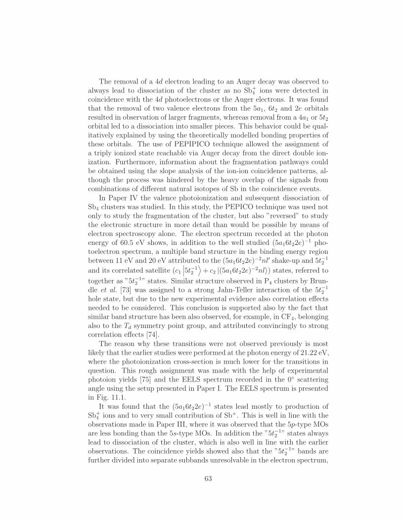
The removal of a 4d electron leading to an Auger decay was observed toalways lead to dissociation of the cluster as no Sb+
4 ions were detected incoincidence with the 4d photoelectrons or the Auger electrons. It was foundthat the removal of two valence electrons from the 5a1, 6t2 and 2e orbitalsresulted in observation of larger fragments, whereas removal from a 4a1 or 5t2orbital led to a dissociation into smaller pieces. This behavior could be qual-itatively explained by using the theoretically modelled bonding properties ofthese orbitals. The use of PEPIPICO technique allowed the assignment ofa triply ionized state reachable via Auger decay from the direct double ion-ization. Furthermore, information about the fragmentation pathways couldbe obtained using the slope analysis of the ion-ion coincidence patterns, al-though the process was hindered by the heavy overlap of the signals fromcombinations of different natural isotopes of Sb in the coincidence events.
In Paper IV the valence photoionization and subsequent dissociation ofSb4 clusters was studied. In this study, the PEPICO technique was used notonly to study the fragmentation of the cluster, but also ”reversed” to studythe electronic structure in more detail than would be possible by means ofelectron spectroscopy alone. The electron spectrum recorded at the photonenergy of 60.5 eV shows, in addition to the well studied (5a16t22e)
−1 pho-toelectron spectrum, a multiple band structure in the binding energy regionbetween 11 eV and 20 eV attributed to the (5a16t22e)
−2nl′ shake-up and 5t−12
and its correlated satellite (c1∣
∣
∣5t−12
⟩
+ c2 |(5a16t22e)−2nl〉) states, referred to
together as ”5t−12 ” states. Similar structure observed in P4 clusters by Brun-
dle et al. [73] was assigned to a strong Jahn-Teller interaction of the 5t−12
hole state, but due to the new experimental evidence also correlation effectsneeded to be considered. This conclusion is supported also by the fact thatsimilar band structure has been also observed, for example, in CF4, belongingalso to the Td symmetry point group, and attributed convincingly to strongcorrelation effects [74].
The reason why these transitions were not observed previously is mostlikely that the earlier studies were performed at the photon energy of 21.22 eV,where the photoionization cross-section is much lower for the transitions inquestion. This rough assignment was made with the help of experimentalphotoion yields [75] and the EELS spectrum recorded in the 0 scatteringangle using the setup presented in Paper I. The EELS spectrum is presentedin Fig. 11.1.
It was found that the (5a16t22e)−1 states lead mostly to production of
Sb+4 ions and to very small contribution of Sb+. This is well in line with the
observations made in Paper III, where it was observed that the 5p-type MOsare less bonding than the 5s-type MOs. In addition the ”5t−1
2 ” states alwayslead to dissociation of the cluster, which is also well in line with the earlierobservations. The coincidence yields showed also that the ”5t−1
2 ” bands arefurther divided into separate subbands unresolvable in the electron spectrum,
63
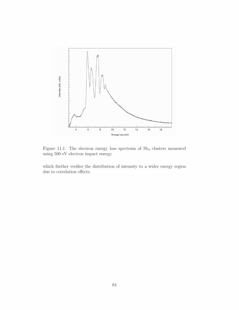
Figure 11.1: The electron energy loss spectrum of Sb4 clusters measuredusing 500 eV electron impact energy.
which further verifies the distribution of intensity to a wider energy regiondue to correlation effects.
64

Chapter 12
Conclusions and future
prospects
The experiments on the shallow core electronic states of Pb and Si give valu-able information about the electronic dynamics and especially the electron-electron correlation effects in heavy and light atoms. Besides its importancein fundamental atomic physics, this knowledge is also important especiallywhen moving towards larger clusters and analyzing the formation of molec-ular orbitals and band structures when closing in on solid structures. Theinformation obtained in Paper VI indicates for example that the 5d5/2 and5d3/2 atomic orbitals participate in the formation of molecular orbitals at dif-ferent stages due to their large energy separation. Also the differing electron-electron interactions in these atomic orbitals are most likely visible also inthe larger systems. For Si, the participation of the 2p electrons in formingmolecular orbitals is unlikely due to its core shell nature.
Expanding the studies to light diatomic molecules, such as KF, yieldsinformation about the vibronic structure of small molecules as well as therelativistic effects in molecular species. It was found that even though KF isa relatively light molecule, the spin-orbit interactions need to be taken intoaccount in order to simulate the absorption spectrum reliably.
In the 4d photoionization and subsequent Auger decay of more compli-cated, tetrahedral Sb4 cluster, it was found that the 4d orbital, deeper inenergy than the corresponding 5d shell in atomic Pb, is very localized incharacter and corresponds already to a core orbital and does not affect thebonding. However, the decay of these core ionized states leaves the clusterin a more unstable state, where two holes are located on the valence orbitals,strongly affecting the bonding. The bonding properties of the valence or-bitals were verified using PEPICO and PEPIPICO techniques following the4d core ionization and valence photoionization. Such experiments should beperformed for other clusters – such as Pb – as well as larger Sb clusters inthe future to further analyze the band formation in these structures.
65
It was found in the studies that correlation effects need to be taken intoaccount in the theoretical calculations in both atoms and molecules if theexperimental spectrum is to be predicted correctly. In Pb the configurationinteraction shows already in the photoionization, whereas in the lighter Si el-ement the states populated through mixing are reflected mostly in the Augerdecay. In KF the mixing of electronic states, after taking the spin-orbit inter-action into account, yields in excited states otherwise unreachable, but stillobserved in the experimental spectrum. The inner valence hole state 5t−1
2 ofSb4 clusters also seem to be strongly correlated as indicated by the compli-cated band structures observed in the photoelectron spectra and PEPICOstudies. This behavior, however, should be further investigated and couldbe verified by studying the experimental electron spectrum, PEPICO andpartial ion yields at the 4d → nl resonances, that can decay to the same(5a16t22e)
−2nl final states via resonant Auger process. These resonances arelocated slightly below the 4d ionization threshold at 38 eV and thus thenew FINEST beamline branch is an ideal platform for studies in this photonenergy region as it also offers exteremely high photon energy resolution forresonant excitation experiments.
In conclusion the experimental work performed in this thesis has yieldedvaluable information about the electronic, vibronic and molecular structureand dynamics of several targets. These experimental results have been usedas a comparison for theoretical calculations and have helped in determiningwhich interactions are the most dominant ones allowing accurate theoreticalmodelling of the spectra.
In addition the work has resulted in two experimental platforms offeringpossibilities for future high resolution electron, ion and EELS spectroscpicstudies as well as for coincidence experiments. The FINEST beamline branch,especially, offers also a platform for other kinds of experiments such as dichro-ism studies employing the circular polarization attainable at the beamline.Also studies combining laser and synchrotron radiation at this beamline areplanned for the future. This technique has been proven useful by a multitudeof studies in the past (see e.g. [76, 77, 78, 79, 80, 81] and references therein).
Using a fluorescence spectrograph at the FINEST beamline allows alsoexperiments on non-ionizing excitations in atoms, molecules and clusters.This would be extremely interesting especially in the case of small clusters,where dissociation can take place well before the ionization threshold. Thephoton energy range of the FINEST beamline offers a possibility to studythe photochemistry of atmospherically and environmentally important com-pounds such as N2O, CH4, CO2, CF4, SO2 etc. at the wavelengths of theSun’s radiation.
Furthermore, as the EELS technique can serve as an equivalent to pho-toabsorption measurements, it can be combined with the absorption studiesperformed at the FINEST beamline to complete transitions which are ei-
66

ther dipole forbidden or do not decay via autoionization and also below theenergies reachable by the FINEST beamline branch. Combining the EELStechnique with laser excitation allows super-elastic scattering studies, whichcan be considered as time-reversed electron-photon coincidence experimentsallowing much faster data collection (see e.g. Ref. [82] and references therein).
67

68

Bibliography
[1] J. J. Thomson, Philos. Mag. 44, 293 (1897)
[2] H. Geiger and E. Marsden, Proc. R. Soc. A 82, 495–500 (1909)
[3] E. Rutherford, Pihols. Mag. 21, 669 – 688 (1911)
[4] M. Planck, Ann. Phys. 4 553 (1901)
[5] A. Einstein, Ann. Phys. 17, 132 (1905)
[6] N. Bohr, Philos. Mag. 26, 1–25 (1913)
[7] L. de Broglie, Ann. Phys. (Paris) 3, 22 (1925)
[8] E. Schrodinger, Phys. Rev. 28, 1049 (1926)
[9] W. Pauli, Z. Physik 31, 765 (1925)
[10] P. A. M. Dirac, Proc. R. Soc. Lond. 117, 610 (1928)
[11] W. Heisenberg, Z. Physik 43, 172 (1927)
[12] M. Born, and P. Jordan, Z. Physik 34, 858–888 (1925)
[13] M. Born, W. Heisenberg, and P. Jordan, Z. Physik 35, 557 – 615 (1925)
[14] K. Siegbahn, C. Nordling, A. Fahlman, R. Nordberg, K. Hamrin, J. Hed-man, G. Johansson, T. Bergmark, S.-E. Karlsson, I. Lindgren, and B.Lindberg, ESCA – atomic, Molecular and Solid State Structure Studiedby Means of Electron Spectroscopy (Almqvist and Wiksells, 1967)
[15] K. Siegbahn, C. Nordling, G. Johansson, J. Hedman, P. F. Heden, K.Hamrin, U. I Gelius, T. Bergmark, L. O. Werme, R. Manne, and Y.Baes, ESCA Applied to Free Molecules (North-Holland, 1969)
[16] F. R. Elder, A. M. Gurewitsch, R. V. Langmuir, and H. C. Pollock,Phys. Rev. 71, 829 – 830 (1947)
69

[17] V. Schmidt, Electron Spectrometry of Atoms Using Synchrotron Radi-ation (Cambridge University Press, Cambridge) (1997)
[18] J. Hillier, and R. F. Baker, J. Appl. Phys 15, 663 (1944)
[19] D. A. McQuarrie, and J. D. Simon, Physical Chemistry: A molecularapproach, University Science Books (Sausalito, California) (1997)
[20] D. C. Harris, and M. D. Bertolucci, Symmetry and spectroscopy: an in-troduction to vibrational and electronic spectroscopy (Oxford UniversityPress, New York) (1978)
[21] H. Jahn, and E. Teller, Proc. R. Soc. Lond. A 161, 220–235 (1937)
[22] M. Inokuti, Rev. Modern Phys. 43, 297–347 (1971)
[23] R. D. Cowan, The Theory of Atomic Structure and Spectra, (Berkeley,CA: University of California Press, 1981)
[24] M. H. Chen, B. Crasemann, H. Mark, Phys. Rev. A 24, 177–182 (1981)
[25] K. J. Ross, and B. Sonntag, Rev. Sci. Instrum. 66, 4409–4433 (1995)
[26] M. Huttula, S. Heinasmaki, H. Aksela, E. Kukk, and S. Aksela, J. Elec-tron Spectrosc. Relat. Phenom. 156–158, 270 (2007)
[27] M. Huttula, K. Jankala, A. Makinen, H. Aksela, and S. Aksela, New. J.Phys. 10, 013009 (2008)
[28] A. Hoffmann, The Physics of Synchrotron Radiation (Cambridge Uni-versity Press, 2004)
[29] U. W. Arndt, X-ray sources, International Tables for CrystallographyF, ch. 6.2, 125–132 (2006)
[30] D. Attwood, Soft X-Rays and Extreme Ultraviolet Radiation (Cam-bridge, UK, 2000)
[31] James A. Clarke, The Science and Technology of Undulators and Wig-glers, Oxford Series on Synchrotron Radiation (Oxford University Press,2004)
[32] M. Huttula, M. Harkoma, E. Nommiste, and S. Aksela, Nucl. Instrum.Methods Phys. Res. A 467, 1514–8 (2001)
[33] M. Huttula, S. Heinasmaki, H. Aksela, E. Kukk, and S.Aksela, J. Elec-tron Spectrosc. Relat. Phenom. 156-8, 270-3 (2007)
70

[34] P. Baltzer, L. Karlsson, M. Lundqvist, and B. Wannberg, Rev. Sci.Instrum. 64, 2179 (1993)
[35] T. X. Carroll, J. D. Bozek, E. Kukk, V. Myrseth, L. J. Sæthre, T. D.Thomas, K. Wiesner, J. Electron Spectrosc. Relat. Phenom. 125, 127–132 (2002)
[36] J. Jauhiainen, A. Ausmees, A. Kivimaki, S. J. Osborne, A. Naves deBrito, S. Aksela, S. Svensson, and H. Aksela, J. Electron Spectrosc.Relat. Phenom. 69, 181–187 (1994)
[37] D. Cubric, D. J. L. Mercer, J. M. Channing, G. C. King, and F. H Read,J. Phys. B: At. Mol. Opt. Phys. 32, L45–L50 (1999)
[38] S. L. Wu, Z. P. Zhong, R. F. Feng, S. L. Xing, B. X. Yang, and K. Z.Xu, Phys. Rev. A 51, 4494 (1995)
[39] V. Feyer, P. Bolognesi, M. Coreno, K. C. Prince, and L. Avaldi, Rad.Phys. Chem. 76, 450–454 (2006)
[40] A. Burose, C. Becker, and A. Ding, Z. Phys. D 20, 35–38 (1991)
[41] A. P. Hitchcock, J. Electron Spectrosc. Relat. Phenom. 112, 9–29 (2000)
[42] F. H. Read, J. Phys. B: At. Mol. Phys. 8, 1034–1040 (1975)
[43] W. C. Wiley, and I. H. McLaren, Rev. Sci. Instrum. 26, 1150–1157(1955)
[44] J. H. D. Eland, Int. J. Mass Spectrom. Ion Phys. 8, 143–151 (1972)
[45] C. J. Danby, and J. H. D. Eland, Int. J. Mass Spectrom. Ion Phys. 8,153–161 (1972)
[46] E. Ruhl, Int. J. Mass Spectrom. 229, 117 (2003)
[47] A. C. F. Santos, C. A. Lucas, and G. G. B. de Souza, Chem. Phys. 282,315 (2002)
[48] A. F. Lago, A. C. F. Santos, and G. G. B. de Souza, J. Chem. Phys.120, 9574 (2004)
[49] M. Simon, M. Lavollee, M. Meyer, and P. Morin, J. Eletron Spectrosc.Relat. Phenom. 79, 401 (1996)
[50] V. Feyer, O. Plekan, R. Richter, M. Coreno, and K. C. Prince, Chem.Phys. 358, 33–38 (2009)
71

[51] E. Kukk, G. Prumper, R. Sankari, M. Hoshino, C. Makochekanwa, M.Kitajima, H. Tanaka, H. Yoshida, Y. Tamenori, E. Rachlew, and K.Ueda, J. Phys. B: At. Mol. Opt. Phys 40, 3677 (2007)
[52] E. Kukk, R. Sankari, M. Huttula, A. Sankari, H. Aksela, and S. Aksela,J. Electron Spectrosc. Relat. Phenom. 155, 141–147 (2007)
[53] G. Prumper, and K. Ueda, Nucl. Instrum. Methods Phys. Res. A 574,350–362 (2007)
[54] M. Sjostrom, E. Wallen, M. Eriksson, and L.-J. Lindgren, Nucl. Instr.and Meth. Phys. Res. A 601, 229–244 (2009)
[55] G. LeBlanc, S. Werin, T. Meinander, H. Ahola, M. Ryynanen, and J.Tahvanainen, Proceedings of EPAC 1999
[56] M. Bassler, J.-O. Forsell, O. Bjorneholm, R. Feifel, M. Jurvansuu, S.Aksela, S. Sundin, S.L. Sorensen, R. Nyholm, A. Ausmees, S. Svensson,J. Electron Spectrosc. Relat. Phenom. 101–103, 953–957 (1999)
[57] M. Bassler, A. Ausmees, M. Jurvansuu, R. Feifel, J.-O. Forsell, P. deTarso Fonseca, A. Kivimaki, S. Sundin, S.L. Sorensen, R. Nyholm, O.Bjorneholm, S. Aksela, and S. Svensson, Nucl. Instr. and Meth. Phys.Res. A 469, 382–393 (2001)
[58] T. Namioka, J. Opt. Soc. Am. 49, 446–460 (1959)
[59] T. Namioka, J. Opt. Soc. Am. 49, 460–465 (1959)
[60] http://www.bestec.de
[61] B. Lai, and F. Cerrina, Nucl. Instrum. Methods in Phys. Res. A 246,337–341 (1986)
[62] D.L. Windt, Comput. Phys. 12, 360–370 (1998)
[63] http://www.xia.com/Differential Pump.html
[64] P. A. Heimann et al., Rev. Sci. Instrum. 68, 1945–51 (1997)
[65] L. Nahon, F. Polack, B. Lagarde, R. Thissen, C. Alcaraz, O. Dutuit, andK. Ito, Nucl. Instrum. Methods in Phys. Res. A 467–8, 453–7 (2001)
[66] http://www.ird-inc.com/axuvope.html
[67] D. Cubric, D. R. Cooper, M. C. A. Lopes, P. Bolognesi, and G. C. King,Meas. Sci. Technol. 10, 554–558 (1999)
72

[68] M. O. Krause, T. A. Carlson, and P. R. Woodruff, Phys. Rev. A 24,1374–9 (1981)
[69] S. H. Southworth, A. C. Parr, J. E. Hardis, J. Dehmer, and D. M. P.Holland, Nucl. Instrum. Methods Phys. Res. A 246, 782–6 (1986)
[70] S. B. Whitfield, R. Wehlitz, M. Martins, Rad. Phys. Chem. 70, 3–42(2004)
[71] B. Sonntag, and P. Zimmermann, Rep. Prog. Phys. 55, 911–987 (1992)
[72] M. Martins, K. Godehusen, T. Richter, P. Wernet, and P. Zimmermann,J. Phys. B: At. Mol. Opt. Phys. 39, R79–R125 (2006)
[73] C. R. Brundle, N. A. Kuebler, M. B. Robin, and H. Basch, Inorg. Chem.11, 20–25 (1972)
[74] D. M. P. Holland et al., Chem. Phys. 308, 43–57 (2004)
[75] R. K. Yoo, B. Ruscic, and J. Berkowitz, J. Electron Spectrosc. Relat.Phenom. 66, 39-54 (1993)
[76] J. Schulz, M. Tchaplyguine, T. Rander, O. Bjorneholm, S. Svensson, R.Sankari, S. Heinasmaki, H. Aksela, S. Aksela, and E. Kukk, Phys. Rev.A 72, 010702(R) (2005)
[77] K. Jankala, J. Schulz, M. Huttula, A. Calo, S. Urpelainen, S.Heinasmaki, S. Fritzsche, S. Svensson, S. Aksela and H. Aksela, Phys.Rev. A 74, 062704 (2006)
[78] A. Moise, M. Alagia, L. Banchi, M. Ferianis, K. C. Prince, and R.Richter, Nucl. Instrum. Methods Phys. Res. A 588, 502–508 (2008)
[79] G. Prumper, S. Kroger, R. Muller, M. Martins, J. Viefhaus, P. Zimmer-mann, and U. Becker, Phys. Rev. A 68, 032710 (2003)
[80] J. Schulz, P. Wernet, M. Martins, B. Sonntag, R. Muller, K. Godehusen,and P. Zimmermann, Phys. Rev. A 67, 012502 (2003)
[81] F. J. Wuilleumier, and M. Meyer, J. Phys. B: At. Mol. Opt. Phys. 39,R425 (2006).
[82] M. Hussey, A. Murray, W. MacGillivray, and G. C. King, Phys. Rev.Lett. 99 133202 (2007)
73