Embed Size (px)
Citation preview

Instrumentation Concepts
Ground-based Optical Telescopes
Keith Taylor(IAG/USP)
Aug-Nov, 2008
Aug-Sep, 2008 IAG-USP (Keith Taylor)
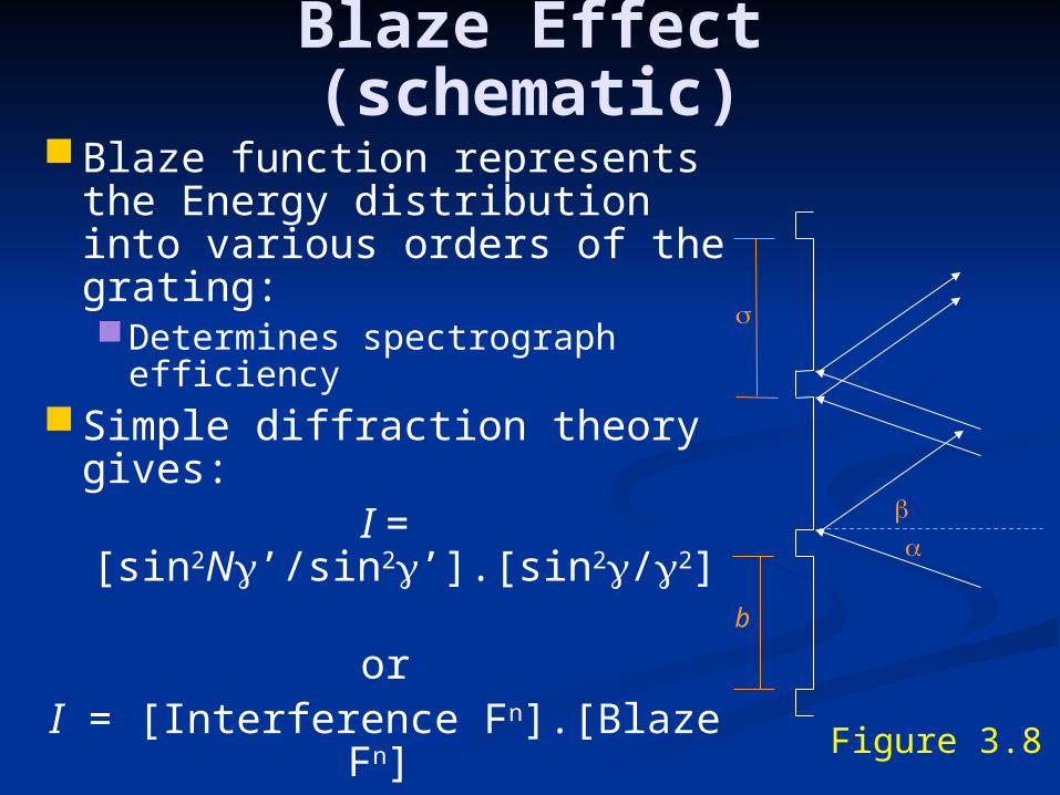
Blaze Effect (schematic)Blaze function represents the
Energy distribution into various orders of the grating:Determines spectrograph
efficiencySimple diffraction theory
gives:I = [sin2N’/sin2’].[sin2/2]
orI = [Interference Fn].[Blaze Fn]
or: I = IF. BFwhere:
’ = phase difference between facets
= phase difference across facets
N = # of recombining beams
b
Figure 3.8

Shape of Blaze Function
b
Figure 3.8
Note:’ = (/).(sin+sin)
ie: the Grating Equation for ’ = m
and = (b/).(sin+sin)
The Blaze Function (BF) is maximum when:
= (or m=0)equivalent to specular reflection
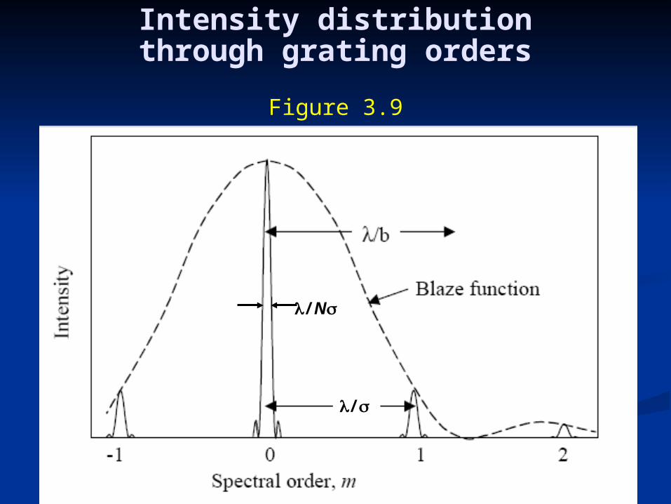
Intensity distributionthrough grating orders
/N
/
Figure 3.9
Free spectral range and Finesse
(for a grating)In reference to previous Figure and
equations:Separation between orders (m=0 &
1) = /Finesse = N = # of recombining
beams
NB: From RD = m.NGeneral case for interferometry (FPs,
FTSs etc)FTS: m = ~105 or more ; N = 2FP: m ~ 103 ; N ~ 30Grating: m ~1 ; N ~105
or moreFor grating: m = 1, 2, 3 …
For m=1: RD = /d = N
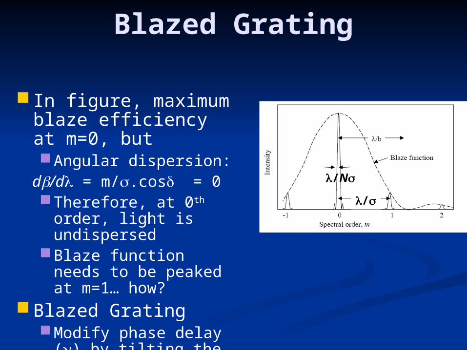
Blazed Grating
In figure, maximum blaze efficiency at m=0, butAngular dispersion:d/d = m/.cos = 0Therefore, at 0th order,
light is undispersedBlaze function needs
to be peaked at m=1… how?
Blazed GratingModify phase delay ()
by tilting the facets ()
/N
/
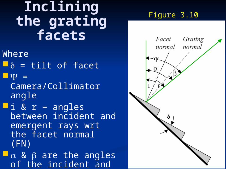
Inclining the grating
facetsWhere = tilt of facet = Camera/Collimator
angle i & r = angles between
incident and emergent rays wrt the facet normal (FN)
& are the angles of the incident and emergent rays wrt the Grating Normal (GN)
Figure 3.10

Blaze peak condition = (.cos/).[sin(-) +
sin(-)] Note: = 0 when 2 = +Hence, from the Grating
Equation
m0 = 2.sin().cos(i)
where: 0 is the blaze wavelength
Note, also: = (cos/).(sin - sin)
and from previous Fig:i = & r =
So Blaze peak condition (=0) occurs
when i = rie: simple specular
reflection

Blaze Wavelength (B)
Also from Grating Equationm B = 2.sin.cos(/2)
Ideally, at the ~40% points:where = /2
= 2mB/(2m1) = 2mB/(2m+1)ie: for m=1 = 2B & = (2/3)B
Also: = B/m … for large m
Figure 3.11

Real grating performance
Physical models of grating behaviour must include:Maxwell’s equations
for a proper analysisPolarization effectsSum of all blaze
energy = 1(Whole lives have
been spent modeling gratings!)
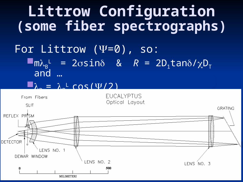
Littrow Configuration(some fiber spectrographs)
For Littrow (=0), so:mB
L = 2sin & R = 2D1tan/DT and …
B = B
L cos(/2)
Aug-Nov, 2008 IAG/USP (Keith Taylor)
Eucalyptus Spectrograph at OPD

Problems with non-Littrow Spectrographs
Beam dilation:Non-zero camera-collimator angle () gives
variable beam dilation (anamorphism) so camera design needs to be compromised
See Fig. 3.5&7Pupil imagery:
Grating represents last surface of diffraction so operates like its own pupil irrespective of where the optical pupil (image of the
telescope formed by the Collimator) is located
So what are the solutions?

Aug-Nov, 2008 IAG/USP (Keith Taylor)
Don’t use a grating!

Aug-Nov, 2008 IAG/USP (Keith Taylor)
Prisms• Multi-object spectrographs often require only low spectral resolution.• Prisms have the advantage that they do not produce multiple orders that can contaminate neighbouring spectra.
• Consider a prism with a refractive index n() with vertex angle and beam diameter D1.The refracted rays are then focussed by a camera. So …
Since: t.n = 2L.cos & = 2
Dispersion can be derived from:d/d = (dn/d).(d/dn)
But: dn/d = (dn/d)/2
= Lsin/t = D1/t
So: d/d = (D1/t).(d/dn)

Aug-Nov, 2008 IAG/USP (Keith Taylor)
Prism Spectral
Resolution
Assume d is the projected width of the spectral resolution element.
Conservation of A (Etendue) give us:DT = d.D2
where: = projected slit-width on the sky
So from before:d = d.(D1/t).(d/dn) = (DT/t).(d/dn)
And then:R = /d = (t/DT).(dn/d)
Aug-Nov, 2008 IAG/USP (Keith Taylor)
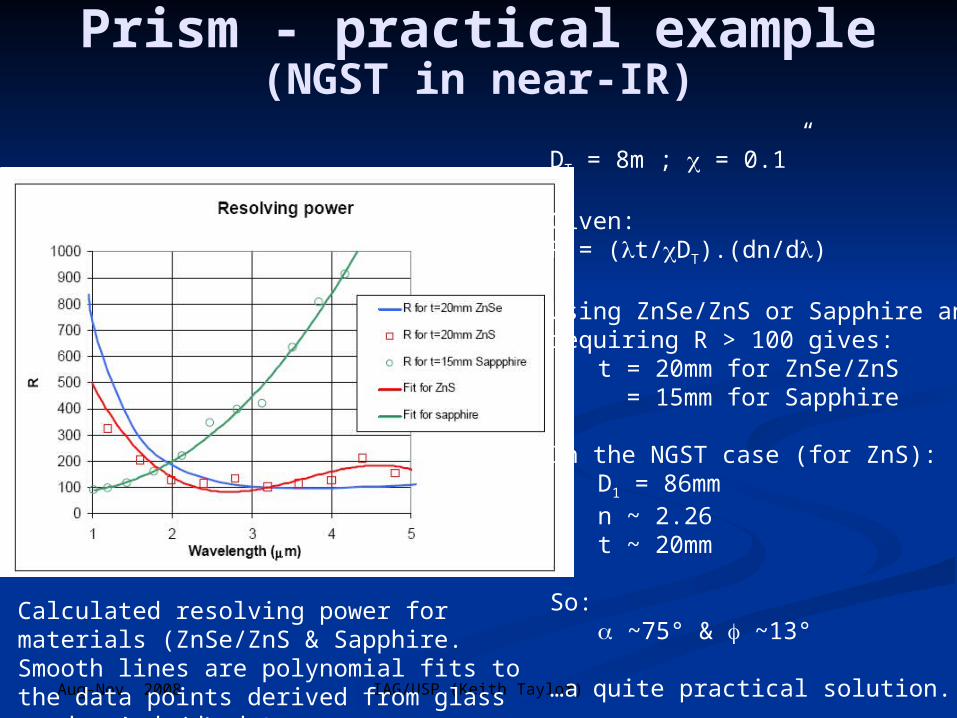
Prism - practical example(NGST in near-IR)
DT = 8m ; = 0.1”
Given:R = (t/DT).(dn/d)
Using ZnSe/ZnS or Sapphire andrequiring R > 100 gives:
t = 20mm for ZnSe/ZnS = 15mm for Sapphire
In the NGST case (for ZnS):D1 = 86mmn ~ 2.26t ~ 20mm
So: ~75° & ~13°
…a quite practical solution.
Calculated resolving power for materials (ZnSe/ZnS & Sapphire. Smooth lines are polynomial fits to the data points derived from glass vendors’ dn/d data.

• Grism = combination of transmission grating and prism (see Fig).
• Grating equation applies but with modification that the refractive index of the medium, n, is included:
• NB: Assume the indices of the prism glass and the resin are the same
n = nG = nR
Grisms = Prism + Grating
The grating equn is thus modified:m/ = n.sinα + n`.sin
Note that the ruling density, , is defined in the
plane of the grating, not the plane normal to the
optical axis of the spectrograph.
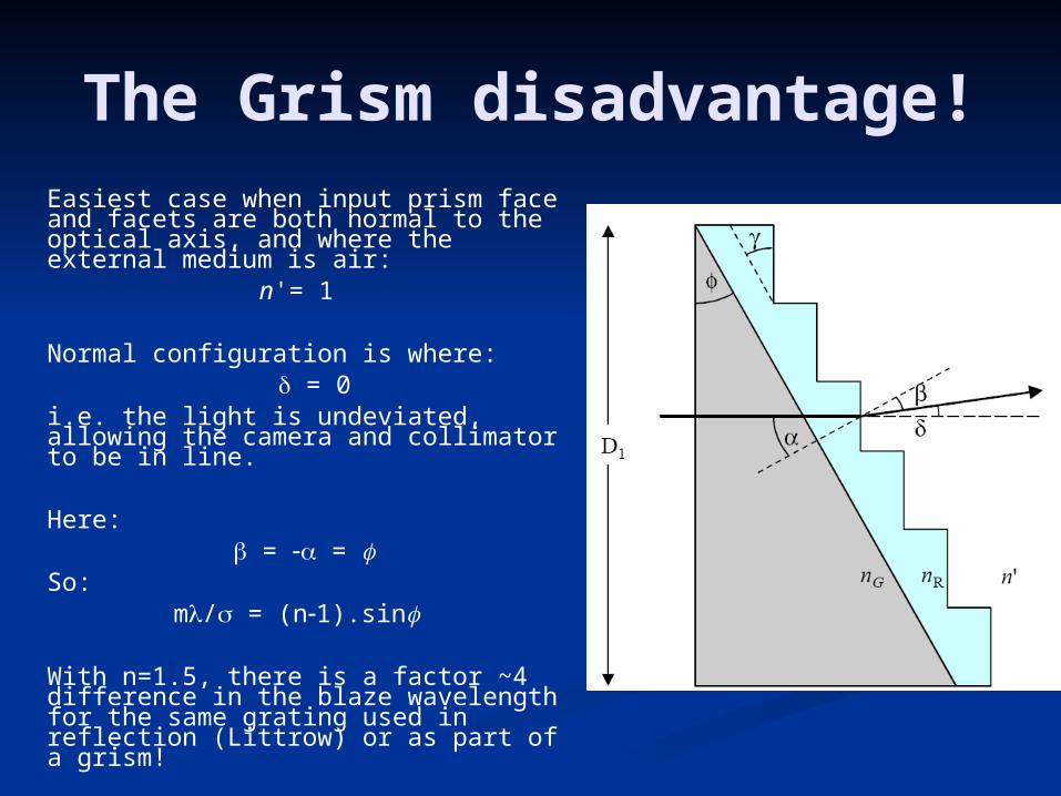
The Grism disadvantage!Easiest case when input prism face and facets are both normal to the optical axis, and where the external medium is air:
n'= 1
Normal configuration is where: = 0
i.e. the light is undeviated, allowing the camera and collimator to be in line.
Here: = =
So:m/ = (n1).sin
With n=1.5, there is a factor ~4 difference in the blaze wavelength for the same grating used in reflection (Littrow) or as part of a grism!
Grism Advantages The advantage of the grism is that the blaze
wavelength image of the target will appear at the same location as a direct image obtained with the grism removed.
There is no anamorphism which means that the camera does not have to accommodate a variety of beam widths
Grisms can be inserted into simple imagers, provided they have an accessible collimated beam.
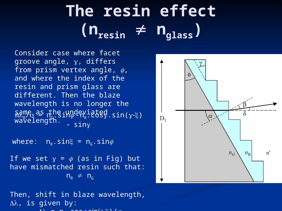
The resin effect(nresin nglass)
Consider case where facet groove angle, , differs from prism vertex angle, , and where the index of the resin and prism glass are different. Then the blaze wavelength is no longer the same as the undeviated wavelength.
mB/ = nG.sin nR.cos.sin() sin
where: nR.sin = nG.sin
If we set = (as in Fig) but have mismatched resin such that:
nR nG
Then, shift in blaze wavelength, , is given by: = nR.cos.sin(-)/

Volume Phase Holographic(VPH) Gratings
Basic principles The gratings discussed so far generate
interference by surface microstructure(ie: surface relief gratings)
VPHGs modulate the refractive index within a volume of the material thus causing phase differences between rays passing through adjacent parts of the material:
Volume Phase Holographic (VPH) gratings
Not to be confused with holographic gratings which are surface relief gratings gratings where the surface shape is generated by a holographic photo-etching process.
VPHGs are Bragg Gratings
VPHGs are Bragg Gratings
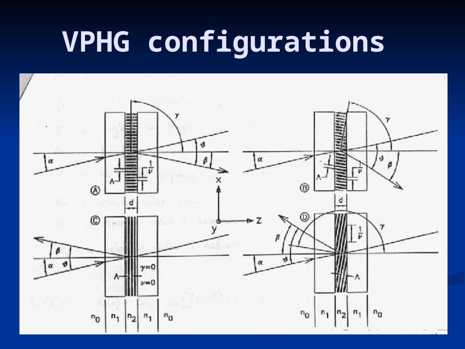
VPHG configurations
VPHG configurations
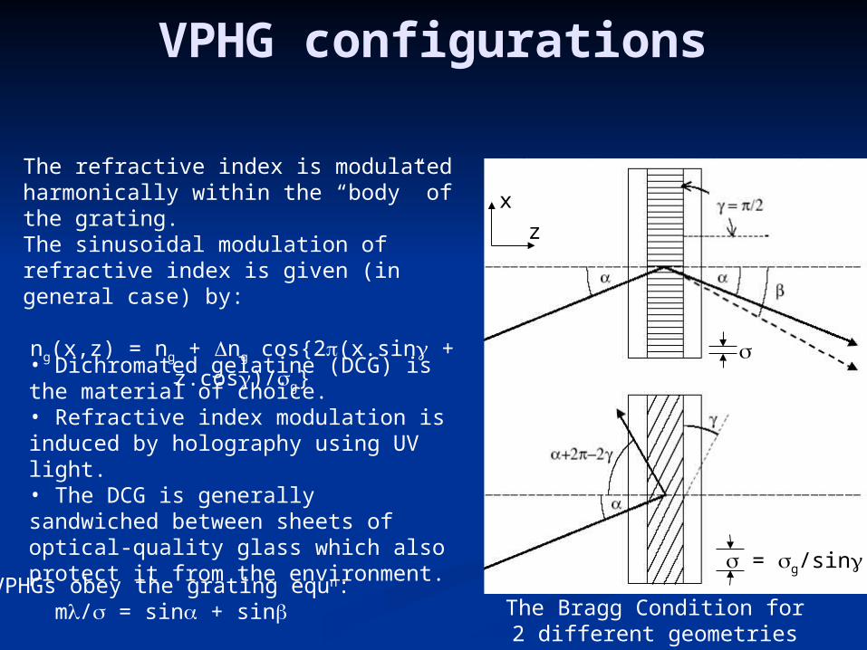
The Bragg Condition for2 different geometries
The refractive index is modulated harmonically within the “body” of the grating.The sinusoidal modulation of refractive index is given (in general case) by:
ng(x,z) = ng + ng cos{2(x.sin + z.cos)/g}
z
x
• Dichromated gelatine (DCG) is the material of choice.• Refractive index modulation is induced by holography using UV light.• The DCG is generally sandwiched between sheets of optical-quality glass which also protect it from the environment.
VPHGs obey the grating equn:m/ = sin + sin
= g/sin

Bragg Diffraction andthe Kogelnik approximation
The diffracted energy pattern is governed by Bragg diffraction giving a maximum when:
mB/ = 2ng.sing
where g is inside the DCG – not in air
As with all gratings, the performance is difficult to model, but Kogelnik’s analysis(see Barden et al.) is applicable in the case where:
2/g2 > 10
where is the thickness of the phase-modulating layer (i.e. the DCG).
In this case, the Bragg condition is satisfied when:ng ~ /2
The lower ng the thicker () the grating has to be (all else being equal!)cf: ng ~ 0.1 for DCG ; ng ~ 0.001 for Doped-glass
VPHG Blaze and Super-blaze
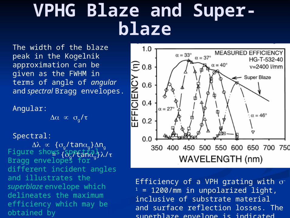
The width of the blaze peak in the Kogelnik approximation can be given as the FWHM in terms of angle of angular and spectral Bragg envelopes.
Angular: g/
Spectral: {g/tang}ng
= {g/tang}/
Efficiency of a VPH grating with -1 = 1200/mm in unpolarized light, inclusive of substrate material and surface reflection losses. The superblaze envelope is indicated. From Barden et al. (2000).
Figure shows spectral Bragg envelopes for different incident angles and illustrates the superblaze envelope which delineates the maximum efficiency which may be obtained bychoosing the optimum combination ofwavelength and incidence angle.

Pros and Cons of VPHGs
Changes in the optical path to the camera as the Braggcondition is changed by tilting the VPH grating.
Advantages:• Efficiency can be very high, ~90% at the superblaze peak (cf: reflection gratings <80% - usually ~60%)• Transmission VPHGs allow compact cameras (near pupil and no anamorphism)• unlike the case for reflection gratings, the blaze (=Bragg) wavelength may be altered (as in figure)• Very high ruling frequencies: -1 ~ 6000 l/mm• Large formats (< 250mm or more)
Disadvantages:• The blaze peak can be relatively narrow making it of limited use in applications where a wide simultaneous wavelength range is required.• Changing the blaze condition involves changing not only the tilt of the grating but also the angle between the collimator and camera. This imposes significant mechanical complexity into the spectrograph.

VPGH spectrographs
Layout showing articulated camera
arrangement
AA Spectrograph(next generation 2dF)

VPH Grisms = “Vrisms”
• Use of a Vrism avoids the “bent” geometry required for a VPH grating.• Possible to make a vrism using a prism cemented to only one side of the VPH grating, if slanted fringes are used (e.g. LDSS++; Glazebrook 1998).• Figure shows the use of two equal prisms (index n1). The prism bends the light to the correct Bragg angle before it strikes the grating and reverses the bend after it, so that the input and output beams are in-line.
In this configuration, = , and the refracted angle in the prism is given by: = - arcsin{sin()/n1}
It is straightforward to show that the resolving power in the Bragg condition is given by:
R = (mW/DT)
= (m/DT).D1(1+tan.tan)
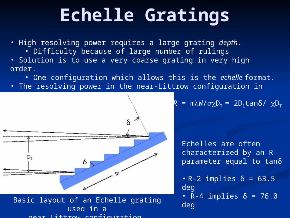
Echelle Gratings• High resolving power requires a large grating depth.
• Difficulty because of large number of rulings• Solution is to use a very coarse grating in very high order.
• One configuration which allows this is the echelle format.• The resolving power in the near-Littrow configuration in which it is usually operated is:
Basic layout of an Echelle grating used in anear-Littrow configuration.
δ
δ
R = mW/DT = 2D1tanδ/ DT
Echelles are often characterized by an R-parameter equal to tanδ
• R-2 implies δ = 63.5 deg• R-4 implies δ = 76.0 deg

World’s largestEchelle Grating

Cross Dispersed EchellesR = mW/DT: so for large R we must maximize (mW/)
• Deep gratings … W is large• R-4 is better than R-2
• (m/) must also be maximized … problems for m~1
2 strategies for maximizing (m/):
a) Decrease while keeping m low:Maximizes free spectral range ( ~ /m)
Problem – producing fine rulings over large surfaces is v. difficult
b) Increase by increasing m:Small free spectral range,
m12 = 2sinδ = m22 = m33 … overlapping orders
So must cross-disperse giving:
The x-dispersed Echelle configuration
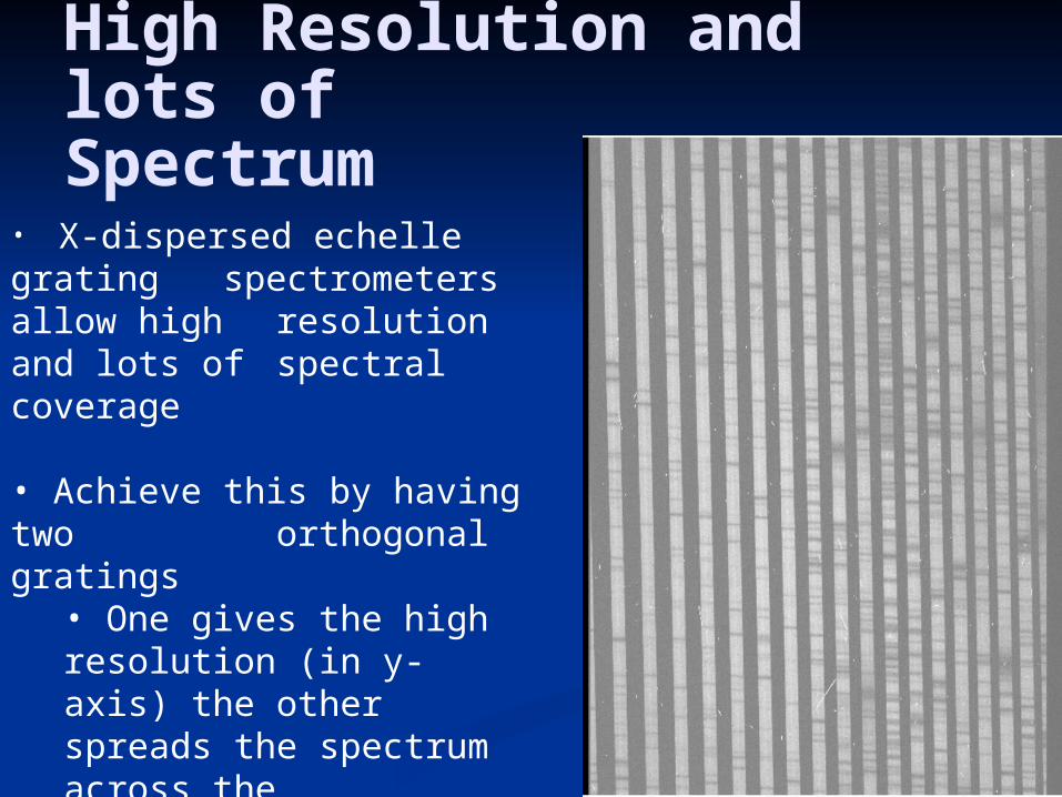
High Resolution and lots ofSpectrum
• X-dispersed echelle grating spectrometers allow high resolution and lots of spectral coverage
• Achieve this by having two orthogonal gratings
• One gives the high resolution (in y-axis) the other spreads the spectrum across the detector(in x-axis)• Slit is consequently much shorter

X-dispersion• Orders are separated by dispersing them at low dispersion (often using a prism).
• X-dispersion is orthogonal to the primary dispersion axis.• With a suitable choice of design parameters, one order will roughly fill the detector in the primary dispersion direction.• With suitable choices of design parameters it is possible to cover a wide wavelength range, say from 300-555nm, as shown in the figure, in a single exposure without gaps between orders.
Illustrative cross-dispersed spectrum showing a simplified layout on the detector.
m = 10-16
• The vertical axis gives wavelength (nm) at the lowest end of each complete order.
• For simplicity the orders are shown evenly spaced in cross-dispersion.
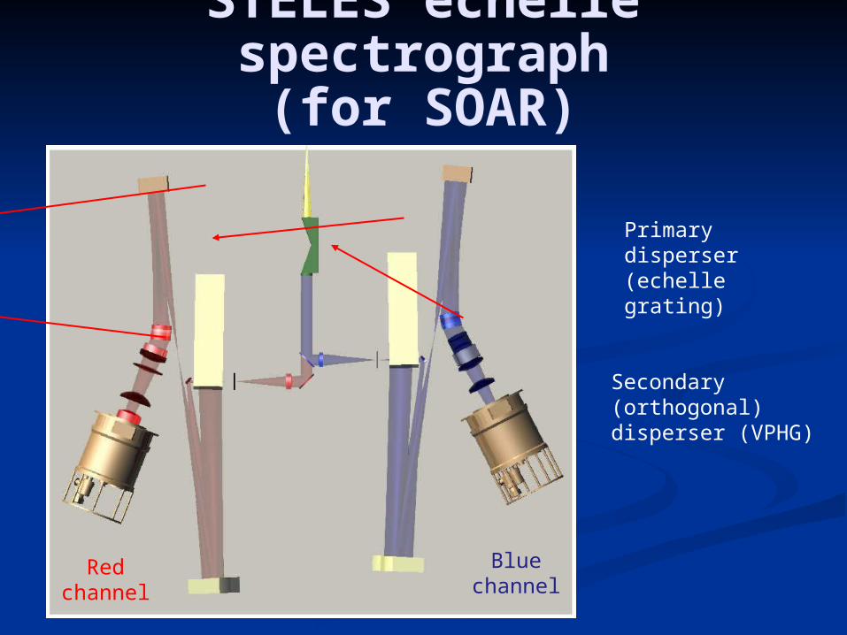
STELES echelle spectrograph(for SOAR)
Primary disperser (echelle grating)
Secondary (orthogonal) disperser (VPHG)
Redchannel
Bluechannel