Embed Size (px)
Citation preview

AP 5301/8301Instrumental Methods of Analysis
and Laboratory
Lecture 2
Microscopy (I) Optical
Prof YU Kin Man
E-mail: [email protected]
Tel: 3442-7813
Office: P6422
1
http://www6.cityu.edu.hk/appkchu/AP5301/Notes.htm

Lecture 2: Outline Introduction:
─ Materials characterization techniques
─ Microscopy
Optical microscopy basics
─ Basic concepts
─ Terminologies
─ Resolution
─ Aberrations
Optical microscope
─ Major parts and functions
─ Common modes of analysis Bright and dark field imaging
Polarized microscopy
Phase-contrast microscopy
Differential interference contrast microscopy
Fluorescence microscopy
Scanning confocal optical microscopy
Some examples of applications
2

Introduction: Materials CharacterizationWikipedia:
Characterization, when used in materials science, refers to the broad and
general process by which a material's structure and properties are probed and
measured. It is a fundamental process in the field of materials science, without
which no scientific understanding of engineering materials could be ascertained.
The structure of a material is
determined by its chemical
composition and how it was
synthesized (processed)
A material’s properties will
determine what it can be used
for (applications) and the
performance of the final device.
At the CORE of this tetrahedron
is material characterization
Performance is the ultimate end use function
of the material and is resulted from properly
tuning properties of materials by optimizing
the structure down to the atomic level
through material processing (synthesis).
3
Introduction: this course
Introduces a broad range of advanced materials characterization
techniques─ Basic theory
─ Equipment and operation
─ Applications
These techniques study a wide range of material properties (thin film
and bulk)─ Chemical composition
─ Crystal structure
─ Surface and interfaces
─ Defects: point and extended defects
─ Morphology
─ Electrical, thermal and optical properties
At the end of the course, you should be able to─ Determine the appropriate method(s) to use
─ Understand experimental papers and determine if the data presented by
others are valid
4

Materials characterization techniques
We can broadly classify materials characterization techniques as
imaging and spectroscopic techniques
─ Imaging (microscopy): Optical microscopy, scanning electron
microscopy (SEM), Transmission Electron Microscope (TEM),
Scanning Tunneling Microscope (STM), Scanning probe microscopy
(SPM)
─ Spectroscopy/spectrometry: involves interaction of radiation
(radiative energy) with matter resulting in a plot of the response of
interest as a function of wavelength or frequency (energy)─spectrum:
Energy/Wavelength-Dispersive X-ray spectroscopy (EDX/WDX), X-
Ray Diffraction (XRD), Secondary Ion Mass Spectrometry (SIMS),
Electron Energy Loss Spectroscopy (EELS), Auger electron
spectroscopy (AES), X-ray photoelectron spectroscopy (XPS),
Ultraviolet-visible-near infrared spectroscopy (UV-vis-NIR),
spectroscopic ellipsometry, Photo/Cathodo-luminescence (PL/CL)
─ Electrical/thermal probes: Four point probe, Hall effect, Capacitance-
Voltage (CV), Thermal Power (Seeback)
5

Course Outline
Week Date Topic
1 8-30 Introduction (Chu)
2 9-06 Microscopy (I): Optical microscopy
3 9-13 Microscopy (II): SEM and Scanning probe
4 9-20 TEM & Electron probe microanalysis
5 9-27 X ray diffraction
6 10-04 Electrical measurements: four point probe, Hall, C-V, thermal
probe, minority carrier lifetime
7 10-11 Optical spectroscopies: spectrophotometry,
photoluminescence, spectroscopic ellipsometry, modulation
spectroscopy
8 10-18 Secondary Ion Mass Spectrometry (SIMS)
9 10-25 Auger Electron Spectroscopy (AES) (Chu)
10 11-01 X-ray Photoelectron Spectroscopy (XPS) (Chu)
11 11-08 Ion Beam techniques: RBS, PIXE, channeling
12 11-15 review
13 11-22 open
FINAL EXAM
6

Microscopy7
To provide a magnified image
To observe features that are beyond the resolution of the human
eyes (~100mm)
─ directly by light (optical) microscope using visible light
─ other microscopy imaging techniques use some other interaction probe
and response signal (usually electrons) to provide the contrast that
produces an image.
Able to “sense” depth
─ in the light microscope, topological contrast is provided largely by
shadowing in reflection,
─ in Scanning Electron Microscopy (SEM) secondary electrons are
generated from different depths, giving rise to topological contrast,
─ in Transmission Electron Microscopy (TEM), no depth information is
obtained.
For materials characterization, light Microscope is likely to be the
first imaging instrument to use
─ the cheapest “modern” instrument and take up the least physical space

Biomotor using ATP
DNA
~2 nm wide
The scale of things
The Microworld
0.1 nm
1 nan
om
eter (nm
)
0.01 mm
10 nm
0.1 mm
100 nm
1 micro
meter (m
m)
0.01 mm
10 mm
0.1 mm
100 mm
1 millim
eter (mm
)
0.01 m
1 cm
10 mm
0.1 m
100 mm
1 meter (m
)10
0m
10-1
m
10-2
m
10-3
m
10-4
m
10-5
m
10-6
m
10-7
m
10-8
m
10-9
m
10-10
m
Visiblespectrum
The Nanoworld
Cat~ 0.3 mMonarch butterfly
~ 0.1 mDust mite300 mm
Bee~ 15 mm
Human hair~ 50 mm wide
Magnetic domains garnet film
11 mm wide stripes
Red blood cellswith white cell
~ 2-5 mm
10
nm
Cell membrane
ATP synthaseSchematic, central core
Atoms of siliconspacing ~tenths of nm
Quantum corral of 48 iron atoms on copper surfacepositioned one at a time with an STM tip
Corral diameter 14 nm
Self-assembled “mushroom”
MEMS (MicroElectroMechanical Systems) Devices10 -100 mm wide
Red blood cellsPollen grain
Head of a pin1-2 mm
Microelectronics
Objects fashioned frommetals, ceramics, glasses, polymers ...
8

Optical vs. electron microscopy9
Microstructure of steel D2
(Metal Ravne Steel Selector)
Glass ceramic transmission microscope image
made with polarized light and full wave plate
Exfoliated molybdenum
disulfide on a perforated gridOptical Microscope
Electron Microscope
Atomic resolution TEM image of
nanocrystalline palladium. H. Rösner and C.
Kübel et al., Acta Mat., 2011, 59, 7380-7387.
Cross-section TEM image of MOCVD
grown InGaAs/GaAs quantum dot
superlattice solar cell (NREL)SEM micrographs of SMNb0.05%
Mat. Res. vol.6 no.2 São Carlos
Apr./June 2003.
Scanning electron microscopy (SEM) image
of as-grown p-type gallium nitride (p-GaN)
nanowire arrays on a silicon (111) substrate

Optical (light) microscopy
Introduction
Basic principles
─ Lens formula, Image formation and Magnification
─ Resolution and lens defects
Basic components and their functions
Common modes of analysis: bright field and dark field
Specialized Microscopy Techniques
─ Polarized light microscopy
─ Phase contrast microscopy
─ Differential interference contrast (DIC) microscopy
─ Fluorescence microscopy
─ Scanning confocal optical microscopy (SCOM)
Typical examples of applications
http://micro.magnet.fsu.edu/primer
http://www.doitpoms.ac.uk/tlplib/optical-microscopy/index.php
10

Introduction
An optical microscope:
uses visible light as the illumination source,
has lateral resolution down to 0.1mm (typically a few mm),
can be used for almost all solids and liquid crystals,
is typically nondestructive; sample preparation may involve
material removal,
is mainly used for direct visual observation; preliminary
observation for final characterization with applications in
geology, medicine, materials research and engineering,
industries, etc.
Typical microstructural features observed in materials science
are grains, precipitates, inclusions, pores, whiskers, defects,
twin boundaries, etc.
http://www.youtube.com/watch?v=bGBgABLEV4g&feature=endscreen&NR=1 using a microscope
11

Light microscope: parts12
Base – Base supports the microscope
which is horseshoe shaped
Illuminator - This is the light source located
below the specimen.
Iris diaphragm - Regulates the amount of
light into the condenser.
Condenser - Focuses the ray of light
through the specimen.
Stage - The fixed stage is a horizontal
platform that holds the specimen.
Nosepiece - The portion of the body that
holds the objectives over the stage.
Objective - The lens that is directly above the stage.
Coarse focusing knob - Used to make relatively wide focusing adjustments to
the microscope.
Fine focusing knob - Used to make relatively small adjustments to the
microscope.
Body - The microscope body.
Ocular eyepiece - Lens on the top of the body tube. It has a magnification of 10×
normal vision.

Light microscopes: then and now
http://www.youtube.com/watch?annotation_id=annotation_100990&feature=iv&src_vid=L6d3zD2LtSI&v=ntPjuUMdXbghttp://www.youtube.com/watch?v=X-w98KA8UqU&feature=related
http://www.youtube.com/watch?v=sCYX_XQgnSA&feature=related <2min
http://www.youtube.com/watch?v=1k659rtLrhk <2min
13

Basic concepts14
Magnification: the ratio of the size of an object seen under the microscope
to the actual size observed with unaided eye.
─ The total magnification of a microscope is calculated by multiplying the
magnifying power of the objective lens by that of eye piece
Resolving power: the ability to differentiate two close points as separate
─ The resolving power of human eye is 0.25 mm
─ The light microscope can separate dots that are 0.25µm apart.
─ The electron microscope can separate dots that are 0.5nm apart
Limit of resolution (resolving power) : is the minimum distance
between two points to identify them separately.
Abbe diffraction limit:
resolving power, RP=𝑤𝑎𝑣𝑒𝑙𝑒𝑛𝑔𝑡ℎ 𝑜𝑓 𝑙𝑖𝑔ℎ𝑡
2 × 𝑛𝑢𝑚𝑒𝑟𝑖𝑐𝑎𝑙 𝑎𝑝𝑒𝑟𝑡𝑢𝑟𝑒 𝑜𝑓 𝑡ℎ𝑒 𝑜𝑏𝑗𝑒𝑐𝑡𝑖𝑣𝑒 𝑙𝑒𝑛𝑠
Numerical aperture(NA): 𝑁𝐴 = 𝑛 sin 𝜃, where
n is the index of refraction of the medium, 𝜃 is the
maximal half-angle of the cone of light that can
enter or exit the lens
Focal length

Numerical Aperture (NA)
http://www.youtube.com/watch?v=RSKB0J1sRnU
oil immersion objective use in microscope at~0:33
𝑁𝐴 = 𝑛(sin )
Immersion oil
n=1.515
Air
n=1.0
Imaging Medium
15

Basic concept: Absorption16
When light passes through an object the intensity is reduced
depending upon the color absorbed. Thus the selective absorption of
white light produces colored light.
The Beer–Lambert law relates the attenuation of light to the
properties of the material through which the light is traveling.
𝐼𝑡(𝜆) = 𝐼𝑜(𝜆)𝑒− 𝛼(𝜆)𝑥
where 𝐼𝑡(𝜆)𝑎𝑛𝑑 𝐼𝑜(𝜆) are the transmitted and incident light intensity and
wavelength 𝜆, respectively, 𝛼(𝜆) is the absorption coefficient of the material
and 𝑥 is the thickness of the material.
The absorbance of an object quantifies
how much of the incident light is
absorbed by it. It is a measure of
attenuation. Absorbance of a
material, denoted A, is given by
𝐴 = 𝑙𝑜𝑔10𝐼𝑜𝐼𝑡
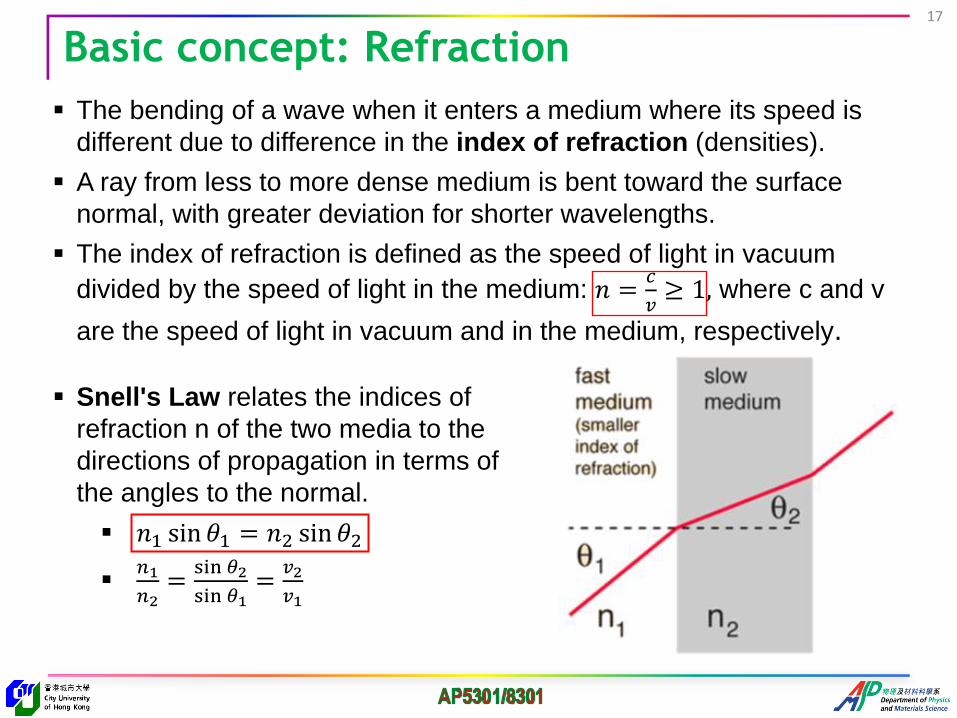
Basic concept: Refraction17
The bending of a wave when it enters a medium where its speed is
different due to difference in the index of refraction (densities).
A ray from less to more dense medium is bent toward the surface
normal, with greater deviation for shorter wavelengths.
The index of refraction is defined as the speed of light in vacuum
divided by the speed of light in the medium: 𝑛 =𝑐
𝑣≥ 1, where c and v
are the speed of light in vacuum and in the medium, respectively.
Snell's Law relates the indices of
refraction n of the two media to the
directions of propagation in terms of
the angles to the normal.
𝑛1 sin 𝜃1 = 𝑛2 sin 𝜃2
𝑛1
𝑛2=
sin 𝜃2
sin 𝜃1=
𝑣2
𝑣1

Basic concept: Refraction
http://micro.magnet.fsu.edu/primer/java/refraction/refractionangles/index.html
http://www.youtube.com/watch?v=jQDRNb-E-cY ~1.00–2:20
18
Material n
Vacuum 1.0000
Air 1.000277
Ice 1.31
Water 1.333
Ethyl alcohol 1.362
Lucite 1.47
Glass 1.52
Polystyrene 1.59
Diamond 2.417

Basic concept: Diffraction19
Diffraction manifests itself in the apparent bending of waves
around small obstacles and the spreading out of waves past
small openings.
Diffraction provides a powerful tool for studying the geometry of
objects that are too small to be viewed directly.
Will be covered in more detail when we talk about x-ray diffraction

Basic concept: Dispersion20
Chromatic dispersion is the change of index of refraction with
wavelength.
─ Generally the index decreases as wavelength increases (𝒏 ↓ 𝝀 ↑)
─ Blue light (~400 nm) travels slower in the material than red light (~700nm).
Dispersion is the phenomenon which gives you the separation of colors
in a prism. It also gives the generally undesirable chromatic
aberration in lenses.
http://hyperphysics.phy-astr.gsu.edu/hbase/hph.html

Light microscope: a little history21
In 1590 F.H Janssen & Z. Janssen
constructed the first simple compound light
microscope.
In 1665 Robert Hooke developed a first
laboratory compound microscope.
Later, Kepler and Galileo developed a modern
class room microscope.
In 1672 Leeuwenhoek developed a simple
microscope with a magnification of 275x. He is
mistakenly called "the inventor of the microscope“
In 1880 Abbe and Zeiss developed oil immersion
systems and were able to make the a Numeric
Aperture (N.A.) to the maximum of 1.4 allowing
light microscopes to resolve two points distanced
only 0.2 microns apart.
Remember that: RP=𝜆
2×𝑁𝐴

A typical light microscope22

Basics: focusing by a curved surface
In entering an optically more dense medium (𝑛𝟐 > 𝑛𝟏), rays are bent
toward the normal to the interface at the point of incidence.
Curved (converging) glass surface
F - focal point f – focal length
normal
F
f
𝑛𝟐𝑛𝟏
Focal plane
Air
23

Basics: principal focal length24
For a thin double convex lens, refraction acts to focus all parallel
rays to a point referred to as the principal focal point.
The distance from the lens to that point is the principal focal length
f of the lens
For a double concave lens where the rays are diverged, the
principal focal length is the distance at which the back-projected rays
would come together and it is given a negative sign.
The lens strength in diopters is defined as the inverse of the focal
length in meters.
𝑃(𝑑𝑖𝑜𝑝𝑡𝑒𝑟) =1
𝑓(𝑚)
http://hyperphysics.phy-astr.gsu.edu/hbase/geoopt/foclen.html

Basics: converging (Bi-Convex) lens25
Most lenses are spherical lenses: their two surfaces are parts of the surfaces
of spheres.
A lens is biconvex (or double convex, or just convex) if both surfaces are
convex.
The line joining the centers of the spheres making up the lens surfaces is
called the axis of the lens.
If the lens is biconvex, a collimated beam of light passing through the lens
converges to a spot (a focus) behind the lens─a positive or converging lens.
𝒇 is the focal length of the lens,
𝒏 is the refractive index of the lens
material,
𝑹𝟏 is the radius of curvature (with sign)
of the lens surface closest to the light
source,
𝑹𝟐 is the radius of curvature of the lens
surface farthest from the light source,
𝒅 is the thickness of the lens (the
distance along the lens axis between
the two surface vertices)
+ve-ve

Basics: Lensmaker’s equation26
1
𝑓= (𝑛 − 1)
1
𝑅1−
1
𝑅2+
𝑛 − 1 𝑑
𝑛𝑅1𝑅2
The reciprocal of the focal length,
1/𝑓, is the optical power of the
lens. If the focal length is in meters,
this gives the optical power in
diopters (inverse meters)
For a thin lens where 𝑑 ≪ 𝑅1and 𝑅2:1
𝑓≈ (𝑛 − 1)
1
𝑅1−
1
𝑅2
For a thin bi-convex lens with equal curvatures:1
𝑓≈
2(𝑛−1)
𝑅
http://www.youtube.com/watch?v=R-uMcngNsSk converging (convex) lens<6:10
http://www.youtube.com/watch?v=KYrsmzM9I_8 diverging (concave) lens
http://www.youtube.com/watch?v=Am5wJUEiNAI how it’s made: optical lenses

Image formation27
For a lens of negligible thickness, in air, the distances are
related by the thin lens formula
1
𝑆1+
1
𝑆2=
1
𝑓or
1
𝑖+
1
𝑜=
1
𝑓
http://www.youtube.com/watch?v=-k1NNIOzjFo&feature=related to~3:42
Principal ray
F
F
𝑜 𝑖

Magnification: angular28
The standard close focus distance is
taken as 25 cm
A simple magnifier achieves angular
magnification by permitting the
placement of the object closer to the eye
than the eye could normally focus.
The angular magnification is given
by: 𝑀𝛼=𝛼′
𝛼
http://hyperphysics.phy-astr.gsu.edu/hbase/geoopt/simmag.html
For small angles: 𝛼′
𝛼≈
ℎ′
25ℎ
25
=ℎ′
ℎ=
25
𝑜; using the lens formula:
25
𝑜=
25
𝑓+
25
25
𝛼′
𝛼≈
25
𝑓+ 1; angular magnification 𝑀𝛼=
25
𝑓+ 1
(when the image is at the close focus point of 25 cm)
𝑆1
−𝑆2i
Our eyes are most relaxed while focus at infinity, i.e. 𝑖 = ∞
𝑀𝛼=25
𝑓
A large magnification requires a lens with a small focal length

Magnification: Linear29
The linear magnification or transverse magnification is the ratio of the
image size to the object size. If the image and object are in the same
medium it is just the image distance divided by the object distance.
ℎ𝑜
ℎ𝑖
𝑜 𝑖
𝑀 =ℎ𝑖ℎ𝑜
=−𝑖
𝑜(𝑜𝑟
−𝑆2𝑆1
)
A negative sign is used on the linear magnification equation as a reminder that all
real images are inverted.

𝑠1 𝑠1′
𝑓𝑜
𝑓𝑒
Compound microscope30
A compound microscope uses a very short focal length objective lens to
form a greatly enlarged image. This image is then viewed with a short focal
length eyepiece (Ocular) used as a simple magnifier.
Magnification by the objective 𝑚0 = 𝑠1′/𝑠1
Since 𝑠1′ 𝐿 and 𝑠1 𝑓𝑜, therefore magnification of objective 𝑚𝑜 = −
𝐿
𝑓𝑜
Magnification of the eyepiece 𝑚𝑒 =25
𝑓𝑒(assuming the final image forms at )
Overall magnification 𝑀 = 𝑚𝑜𝑚𝑒 = −𝐿
𝑓𝑜
25
𝑓𝑒
http://www.youtube.com/watch?v=kcyF4kLKQTQ at~1:57
http://www.youtube.com/watch?v=RKA8_mif6-E

Microscope resolution31
The resolution of an optical microscope is
defined as the shortest distance between two
points on a specimen that can still be
distinguished by the observer as separate
entities.
The diffraction pattern resulting from a uniformly-
illuminated circular aperture has a bright region
in the center, known as the Airy disk, which
together with the series of concentric bright rings
around is called the Airy pattern.
The lens' circular aperture is analogous to a two-
dimensional version of the single-slit
experiment. Light passing through the lens
interferes with itself creating a ring-shape Airy
pattern
The limit of resolution of a microscope objective
refers to its ability to distinguish between two
closely spaced Airy disks in the diffraction
pattern.
𝐬𝐢𝐧 = /𝒅
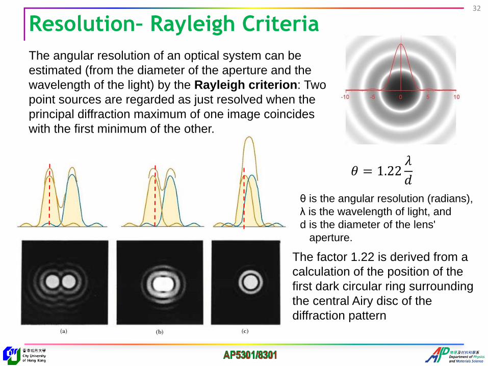
Resolution– Rayleigh Criteria32
The angular resolution of an optical system can be
estimated (from the diameter of the aperture and the
wavelength of the light) by the Rayleigh criterion: Two
point sources are regarded as just resolved when the
principal diffraction maximum of one image coincides
with the first minimum of the other.
𝜃 = 1.22𝜆
𝑑
θ is the angular resolution (radians),
λ is the wavelength of light, and
d is the diameter of the lens'
aperture.
The factor 1.22 is derived from a
calculation of the position of the
first dark circular ring surrounding
the central Airy disc of the
diffraction pattern

Resolution –Linear separation
To express the resolution in terms of a linear
separation r, we have to consider the
Abbe’s theory
Path difference between the two beams
passing the two slits is
𝑑 sin 𝑖 + 𝑑 sin 𝛼 = 𝜆
Assuming that the two beams are just
collected by the objective, then i = and
𝑑𝑚𝑖𝑛 = /2sin
If the space between the specimen and the
objective is filled with a medium of refractive
index n, then wavelength in medium 𝜆𝑛 =𝜆
𝑛
𝑑𝑚𝑖𝑛 =
2𝑛 sin=
𝜆
2(𝑁𝐴)
𝑁𝐴 = 𝑛 sin 𝛼 𝑖𝑠 called numerical aperture
For circular aperture: 𝑑𝑚𝑖𝑛 =1.22𝜆
2(𝑁𝐴)=
0.61𝜆
(𝑁𝐴)
33
𝑑𝑚𝑖𝑛 ~0.3 𝜇𝑚 for a mid-
spectrum of 0.55mm

Axial resolution – Depth of Field34
Another important aspect to resolution is the axial (or longitudinal)
resolving power of an objective, which is measured parallel to the optical
axis and is most often referred to as depth of field.
Depth of field (F in mm) is the range of
distance at the specimen parallel to the
illuminating beam in which the object
appears to be in focus
Depth of focus (f in mm) is the range of
distance at the image plane in which an
object appears to be in focus
Depth of focus varies with numerical
aperture (NA) and magnification (M) of
the objective
─ high NA systems have deeper focus
depths but lower depth of field
M NA f F
M NA f F
http://www.youtube.com/watch?v=FvC2WLUqEug at~3:40
http://micro.magnet.fsu.edu/primer/java/nuaperture/index.html
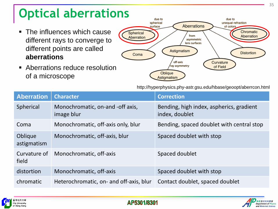
Optical aberrations35
Aberration Character Correction
Spherical Monochromatic, on-and -off axis, image blur
Bending, high index, aspherics, gradient index, doublet
Coma Monochromatic, off-axis only, blur Bending, spaced doublet with central stop
Oblique astigmatism
Monochromatic, off-axis, blur Spaced doublet with stop
Curvature of field
Monochromatic, off-axis Spaced doublet
distortion Monochromatic, off-axis Spaced doublet with stop
chromatic Heterochromatic, on- and off-axis, blur Contact doublet, spaced doublet
The influences which cause
different rays to converge to
different points are called
aberrations
Aberrations reduce resolution
of a microscope
http://hyperphysics.phy-astr.gsu.edu/hbase/geoopt/aberrcon.html

Spherical aberration For lenses made with spherical surfaces, rays which are parallel to the optic
axis but at different distances from the optic axis fail to converge to the same point
The image appears hazy or blur and slightly out of focus.
For a single lens, it can be minimized by bending the lens into its best form.
For multiple lenses, spherical aberrations can be canceled by overcorrecting some elements.
36

The focal length depends on refraction and the index of refraction 𝑛 for blue light (short wavelengths) is larger than that of red light (long wavelengths)
Axial - Blue light is refracted to the greatest extent followed by green and red light, a phenomenon commonly referred to as dispersion
Lateral - chromatic difference of magnification: the blue image of a detail was slightly larger than the green image or the red image in white light, thus causing color ringing of specimen details at the outer regions of the field of view.
Chromatic Aberration37
Achromatic doublet─a strong positive lens made from a low dispersion
glass like crown glass coupled with a weaker negative high dispersion glass
like flint glass calculated to match the focal lengths
An achromatic doublet does not completely eliminate chromatic aberration,
but can eliminate it for two colors

Astigmatism occurs when rays travelling along two perpendicular planes have different image distances for a sharp focus
─ The off-axis image of a specimen point appears as a disc or blurred lines instead of a point.
Comatic aberration occurs due to imperfection in the lens or other components resulting in off-axis point sources such as stars appearing distorted, appearing to have a tail (coma) like a comet.
Curvature of Field - When visible light is focused through a curved lens, the image plane produced by the lens will be curved The image appears sharp and crisp
either in the center or on the edges of the viewfield but not both
Aberrations due to lens imperfection38

Light microscope: basic components and functions
1. Eyepiece (ocular lens)
2. Revolving nose piece (to hold
multiple objective lenses)
3. Objective lenses
4. Focus knobs coarse
5. Focus knobs Fine
6. Stage (to hold the specimen)
7. Light source (lamp)
8. Condenser lens and diaphragm
9. Mechanical stage (move the
specimen on two horizontal axes
for positioning the specimen)
39

Functions of the Major Parts
Lamp and Condenser: project a parallel beam of light onto the sample for illumination
Sample stage with X-Y movement:
sample is placed on the stage and
different part of the sample can be
viewed due to the X-Y movement
capability
Focusing knobs: since the distance
between objective and eyepiece is
fixed, focusing is achieved by moving
the sample relative to the objective lens
40

Major Parts: objective lensObjective: does the main part of magnification and resolves the
fine details on the samples (𝑚𝑜~10 – 100)
Objectives are the most important components of a light microscope:
they are responsible for image formation, magnification, the quality
of images and the resolution of the microscope
𝑑𝑚𝑖𝑛 = 0.61𝜆/𝑁𝐴
41

Eyepieces (Oculars) work in combination with microscope
objectives to further magnify the intermediate image
Major parts: eyepiece Lens
𝑴 = (𝑳/𝒇𝒐)(𝟐𝟓/𝒇𝒆)
Eyepiece: is a cylinder containing two or more lenses; its function is to
bring the image into focus for the eye with typical magnification up to 20x
42

Common light microscopes
Transmitted OM -transparent specimens
─ thin section of rocks,
minerals and single
crystals
Reflected OM - opaque
specimens
─ most metals, ceramics,
semiconductors
Depending on the nature
of samples, either a
transmitted or reflected
optical microscope can be
used
43

Common modes of analysisInstead of using the full illumination of the light source (bright field), it is
sometimes useful to illuminate the sample with peripheral light by blocking the
axial rays─dark field microscopy. This produces the classic appearance of a
dark, almost black, background with bright objects on it
Advantages:
─ A simple procedure which can be used
on live transparent specimens
─ The images appear spectacular and
are visually impressive.
─ Even allows for the visualization of
objects that are below (!) the
resolution of the microscope.
Disadvantages:
─ very sensitive to dirt and dust located
in the light path
─ not suitable for all specimens
─ The intensity of the illumination
system must be high
44

Polarized Light Microscopy45
Polarized light microscopy involves
illumination of the sample with polarized
light.
Designed for specimens that are visible
primarily due to their optically anisotropic
character.
Image contrast arises from the interaction
of plane-polarized light with a
birefringent (or doubly-refracting)
specimen to produce two individual wave
components that are each polarized in
mutually perpendicular planes.
The light components are recombined
with constructive and destructive
interference when they pass through the
analyzer.
Reveals detailed information concerning
the structure and composition of
materials

Phase contrast microscopy46
Phase contrast microscopy uses a special condenser and objective lenses to convert phase differences (not visible) into amplitude differences (visible)
The image contrast is improved in two steps:
─ The background light is phase-shifted by −90° by passing it through a phase-shift ring, leading to an increased intensity between foreground and background
─ To further increase contrast, the background is dimmed by a gray filter ring

Differential interference contrast microscopy Differential interference contrast (DIC) microscopy enhances contrast by creating
artificial shadows (pseudo three-dimensional) using polarized light as if the
object is illuminated from the side
Differential interference contrast converts gradients in specimen optical path
length into amplitude differences that can be visualized as improved contrast
in the resulting image.
47
Blue-green Algae
Phase contrast DIC
The specimen optical path difference is determined by the product of the
refractive index difference (between the specimen and its surrounding medium)
and the geometrical distance (thickness) traversed by a light beam between two
points on the optical path.

Fluorescence microscopy48
A fluorescence microscope uses fluorescence to generate an image
The specimen is illuminated with light of a specific wavelength (or wavelengths) which is absorbed by the fluorophores, causing them to emit light of longer wavelengths (i.e., of a different color than the absorbed light).
The illumination light is separated from the much weaker emitted fluorescence through the use of a spectral emission filter.
Only allows observation of the specific structures which have been labeled for fluorescence
Fluorescent micrograph of an amphibian cell during anaphase
when the chromatids comprising each chromosome disjoin
and move towards their respective poles

Scanning Confocal Optical Microscopy Confocal microscopy is an optical
imaging technique used to increase
optical resolution and contrast of a
micrograph by adding a spatial pinhole
placed at the confocal plane of the
lens to eliminate out-of-focus light.
Scanning confocal optical
microscopy (SCOM) is a technique for
obtaining high-resolution optical
images with depth selectivity. (a laser
beam is used)
The key feature is its ability to acquire
in-focus images from selected
depths, a process known as optical
sectioning.
Images are acquired point-by-point
and reconstructed with a computer,
allowing three-dimensional
reconstructions of topologically complex
objects.
49

Some examples of
applications in materials
science
50

Grain size examination
A grain boundary intersecting a polished surface is not in equilibrium (a).
At elevated temperatures (b), surface diffusion forms a grain-boundary
groove in order to balance the surface tension forces.
a
b
Thermal Etching1200C/30min
20mm
1200C/2h
51
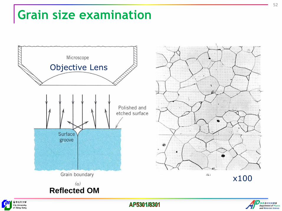
Grain size examination
Objective Lens
x100
Reflected OM
52

Grain growth - reflected OM
Polycrystalline CaF2
illustrating normal grain
growth. Better grain size
distribution.
Large grains in polycrystalline
spinel (MgAl2O4) growing by
secondary recrystallization
from a fine-grained matrix
30mm5mm
53

Liquid phase sintering – reflective OM
Microstructure of MgO-2% kaolin body resulting
from reactive-liquid phase sintering.
Amorphousphase
40mm
54

Image of magnetic domains
Magnetic domains and walls on a (110)-oriented garnet crystal
(Transmitted LM with oblique illumination). The domains
structure is illustrated in (b).
55

Phase identification by reflective polarized OM
YBa2Cu307-x superconductor material: (a) tetragonal phase and (b) orthorhombic phase with multiple twinning (arrowed) (100 x).
56

Internet resources57
http://www.youtube.com/watch?v=4RijnutOU4o
http://micro.magnet.fsu.edu/primer/java/aberrations/astigmatism/index.html
http://www.youtube.com/watch?v=yQ4rDNOX7So at~3:27-4:15
Astigmatism
http://www.youtube.com/watch?v=EXmaY2txEBo&list=PL02D1D436A44B521A&index=4
http://micro.magnet.fsu.edu/primer/java/aberrations/coma/index.html
Comatic aberration
http://www.youtube.com/watch?v=E85FZ7WLvao
http://micro.magnet.fsu.edu/primer/java/aberrations/spherical/index.html
http://www.youtube.com/watch?v=MKNFW0YwDYw -Canon lens production
Spherical aberration
Chromatic aberration
http://www.youtube.com/watch?v=yH7rbRu7Av8&list=PL02D1D436A44B521A chromatic aberration
http://www.youtube.com/watch?v=H8PQ9RMUoA8 at~3:30-4:30
http://micro.magnet.fsu.edu/primer/java/aberrations/curvatureoffield/index.html
Curvature of field

Basic components and their functions
http://www.youtube.com/watch?v=RKA8_mif6-E
Microscope Review (simple, clear)
http://www.youtube.com/watch?v=b2PCJ5s-iyk
Microscope working in animation (How to use a microscope)
http://www.youtube.com/watch?annotation_id=annotation_100990&feature=iv&src_vid=L6d3zD2
LtSI&v=ntPjuUMdXbg (I) http://www.youtube.com/watch?v=VQtMHj3vaLg (II)
Parts and Function of a Microscope (details)
http://www.youtube.com/watch?v=X-w98KA8UqU&feature=related
How to use a microscope (specimen preparation at~1:55-2:30)
http://www.youtube.com/watch?v=bGBgABLEV4g
How to care for and operate a microscope
58

Do review problems (1-9) on OM
http://www.doitpoms.ac.uk/tlplib/optical-microscopy/questions.php
59