Embed Size (px)
Citation preview
fl
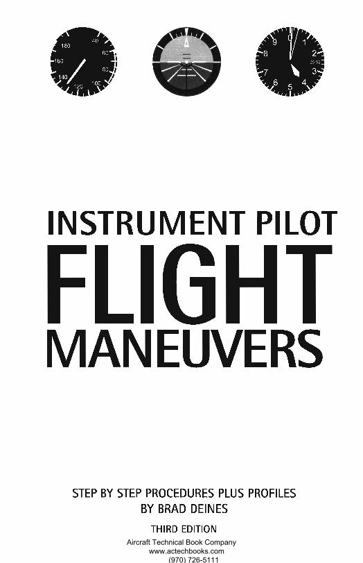
INSTRUMENT PILOT
FLIGHTMANEUVERS
STEP BY STEP PROCEDURES PLUS PROFILESBY BRAD DEINES
THIRD EDITIONAircraft Technical Book Company
www.actechbooks.com (970) 726-5111
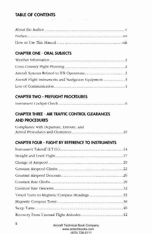
TABLE OF CONTENTS
About the Author
Preface vii
How to Use This Manual viii
CHAPTER ONE - ORAL SUBJECTS
Weather Information 2
Cross-Country Flight Planning 2
Aircraft Systems Related to IFR Operations 3
Aircraft Flight Instruments and Navigation Equipment 3
Loss of Communication 4
CHAPTER TWO - PREFLIGHT PROCEDURES
Instrument Cockpit Check 6
CHAPTER THREE - AIR TRAFFIC CONTROL CLEARANCES
AND PROCEDURES
Compliance with Departure, Enroute, andArrival Procedures and Clearances 10
CHAPTER FOUR - FLIGHT BY REFERENCE TO INSTRUMENTS
Instrument Takeoff (I.T.O.) 14
Straight and Level Flight 17
Change of Airspeed 20
Constant Airspeed Climbs 22
Constant Airspeed Descents 26
Constant Rate Climbs 29
Constant Rate Descents 32
Timed Turns to Magnetic Compass Headings 35
Magnetic Compass Turns 38
Steep Turns 40
Recovery From Unusual Flight Attitudes 42
3
A IF
Aircraft Technical Book Company www.actechbooks.com
(970) 726-5111
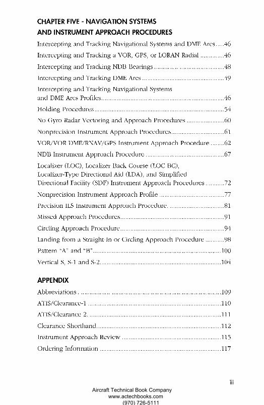
CHAPTER FIVE - NAVIGATION SYSTEMSAND INSTRUMENT APPROACH PROCEDURES
Intercepting and Tracking Navigational Systems and DME Arcs 46
Intercepting and Tracking a VOR, GPS, or LORAN Radial 46
Intercepting and Tracking NDB Bearings 48
Intercepting and Tracking DME Arcs 49
Intercepting and Tracking Navigational Systemsand DME Arcs Profiles 46
Holding Procedures 54
No-Gyro Radar Vectoring and Approach Procedures 60
Nonprecision Instrument Approach Procedures 61
VOR/VOR DME/RNAV/GPS Instrument Approach Procedure 62
NDB Instrument Approach Procedure 67
Localizer (LOC), Localizer Back Course (LOC BC),Localizer-Type Directional Aid (LDA), and SimplifiedDirectional Facility (SDF) Instrument Approach Procedures 72
Nonprecision Instrument Approach Profile 77
Precision ILS Instrument Approach Procedure. 81
Missed Approach Procedures 91
Circling Approach Procedure 94
Landing from a Straight-In or Circling Approach Procedure 98
Pattern "A" and "B" 100
Vertical S, S-1 and S-2 104
APPENDIX
Abbreviations 109
ATIS/Clearance-1 110
ATIS/Clearance-2. 111
Clearance Shorthand 112
Instrument Approach Review 115
Ordering Information 117
iii
EAircraft Technical Book Company
www.actechbooks.com (970) 726-5111
Ja.
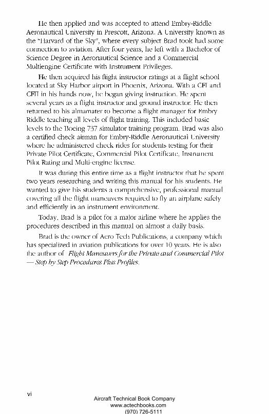
He then applied and was accepted to attend Embry-RiddleAeronautical University in Prescott, Arizona. A University known asthe "Harvard of the Sky", where every subject Brad took had someconnection to aviation. After four years, he left with a Bachelor ofScience Degree in Aeronautical Science and a CommercialMultiengine Certificate with Instrument Privileges.
He then acquired his flight instructor ratings at a flight schoollocated at Sky Harbor airport in Phoenix, Arizona. With a CFI andCFII in his hands now, he began giving instruction. He spentseveral years as a flight instructor and ground instructor. He thenreturned to his almamater to become a flight manager for Embry-Riddle teaching all levels of flight training. This included basiclevels to the Boeing 737 simulator training program. Brad was alsoa certified check airman for Embry-Riddle Aeronautical Universitywhere he administered check rides for students testing for theirPrivate Pilot Certificate, Commercial Pilot Certificate, InstrumentPilot Rating and Multi-engine license.
It was during this entire time as a flight instructor that he spenttwo years researching and writing this manual for his students. Hewanted to give his students a comprehensive, professional manualcovering all the flight maneuvers required to fly an airplane safelyand efficiently in an instrument environment.
Today, Brad is a pilot for a major airline where he applies theprocedures described in this manual on almost a daily basis.
Brad is the owner of Aero Tech Publications, a company whichhas specialized in aviation publications for over 10 years. He is alsothe author of Flight Maneuvers for the Private and Commercial Pilot— Step by Step Procedures Plus Profiles.
CC
vi Aircraft Technical Book Company www.actechbooks.com
(970) 726-5111
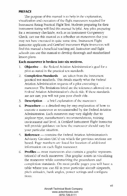
PREFACE
The purpose of this manual is to help in the explanation,visualization and execution of the flight maneuvers required forInstrument Rating Practical Flight Test. Students preparing for theirInstrument Rating will find this manual helpful. Any pilot preparingfor a recurrency checkride, such as an Instrument CompetencyCheck, can use this manual as a refresher on maneuvers that youmay not have executed in quite some time. Instrument FlightInstructor applicants and Certified Instrument Flight Instructors willfind this manual a beneficial teaching aid. Instructors and flightschools can use this manual to develop thorough and standardizedlesson plans.Each maneuver is broken into six sections.
Objective — the Federal Aviation Administration's goal for apilot as stated in the practical test standards.Completion Standards — are taken from the instrumentpractical test standards. This details exactly what the FederalAviation Administration requests of a pilot executing amaneuver. The limitations listed are the tolerances allowed on aFederal Aviation Administration's check ride. If these standardsare not met, you will not pass your check ride.
Description — a brief explanation of the maneuver.
Procedure — a detailed step by step explanation of how toexecute a maneuver as recommended by the Federal AviationAdministration. Each maneuver may vary slightly due toairplane type, manufacturer's recommendations, trainingenvironment and level. A Certified Instrument Flight Instructorwill provide guidance on how the maneuver should vary foryour particular situation.Reference — contains the Federal Aviation Administration'sAdvisory Circulars (AC's) on which the previous sections arebased. Page numbers are listed for location of additionalinformation on each flight maneuver.Profiles — most maneuvers also contain a graphic represen-tation(s) of each maneuver. This graphic assists in visualizingthe maneuver while summarizing the procedures andcompletion standards. On most profile pages you will have atable where you can fill in your particular aircraft airspeeds,pitch attitudes, bank angles, power settings and configura-tions.
viiAircraft Technical Book Company
www.actechbooks.com (970) 726-5111
All airspeeds, pitch attitudes, bank angles, power settings andconfigurations are referenced from the 1984 Cessna 172P Pilot'sOperating Handbook based on sea level, maximum gross weight,and standard atmospheric conditions. All these settings may vary dueto altitude, temperature, humidity, winds, airplane weight andconfigurations. Consult your airplane Pilot's Operating Handbookand/or your flight instructor for the proper airspeeds, pitch attitudes,bank angles, power settings and configurations.
HOW TO USE THIS MANUAL
Before every flight lesson, know exactly what flight maneuverswill be practiced. Reference your flight syllabus for the maneuvers tostudy. Divide the list into two sections: New Maneuvers for themaneuvers your instructor is going to introduce or teach for the firsttime; and Review Maneuvers, for maneuvers you are familiar withbut will be practicing on your next flight lesson.
New Maneuvers — Start by reading the maneuver's sixsections. If there are questions on a particular step in the maneuver,reference the appropriate Federal Aviation Administration AdvisoryCircular or other references listed for each maneuver. If an answercannot be found, write it down and ask your instructor during thepre-flight briefing. Go over the procedure section several times untilyou every step memorized. Practice the maneuver by "chair flying"the step by step procedure. (Chair Flying - visually flying themaneuver in your comfortable chair at home). By doing all thispreparation, you will impress your flight instructor with yourknowledge and understanding of the maneuver before you evenstep into an airplane. Not to mention the money you will save in lessdual flying time.
Review Maneuvers — The profile section in most cases willcontinue to refresh your memory on the steps required to completethe maneuver. If it has been several weeks since practicing thismaneuver, it may be best to follow the steps listed for a newmaneuver. Continue to "chair fly" the maneuver on your off days tomaintain your proficiency.
x.
viii Aircraft Technical Book Company www.actechbooks.com
(970) 726-5111
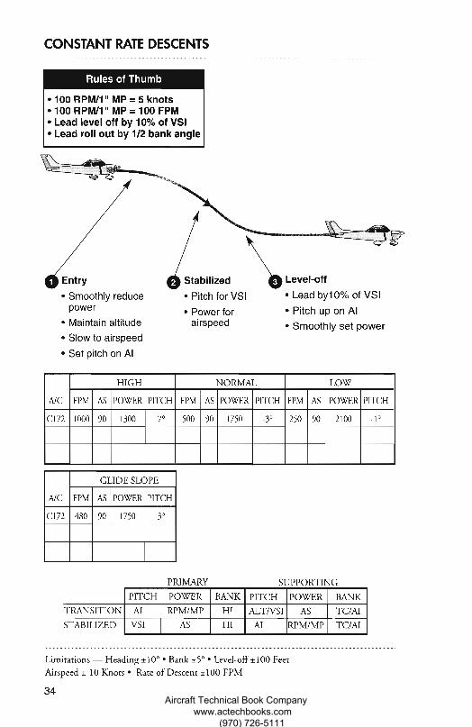
Entry Stabilized
Smoothly reduce • Pitch for VSIpower • Power forMaintain altitude airspeed
Slow to airspeed
Set pitch on Al
Level-off
Lead byl 0% of VSI
Pitch up on Al
Smoothly set power
Rules of Thumb
100 RPM/1" MP = 5 knots100 RPM/1" MP = 100 FPMLead level off by 10% of VSILead roll out by 1/2 bank angle
CONSTANT RATE DESCENTS
A/C
HIGH NORMAL LOW
FPM AS POWER PITCH FPM AS POWER PITCH FPM AS POWER PITCH
C172 1000 90 1300 -7° 500 90 1750 -3° 250 90 2100 -1°
GLIDE SLOPE
A/C FPM AS POWER PITCH
C172 480 90 1750 -3°
PRIMARY
SUPPORTING
41.
4IP
PITCH POWER BANK PITCH POWER BANK
AI RPM/MP HI ALT/VSI AS TC/AI
VSI AS HI AI RPM/MP TC/AI
TRANSITION
STABILIZED
Limitations — Heading ±10° • Bank ±5° • Level-off ±100 FeetAirspeed ± 10 Knots • Rate of Descent ±100 FPM
34 Aircraft Technical Book Company www.actechbooks.com
(970) 726-5111
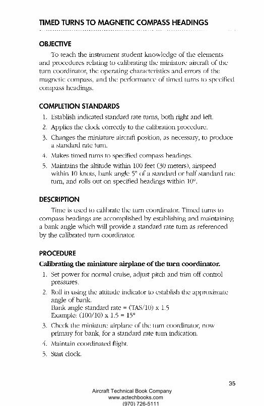
TIMED TURNS TO MAGNETIC COMPASS HEADINGS
OBJECTIVE0 To teach the instrument student knowledge of the elements
and procedures relating to calibrating the miniature aircraft of theturn coordinator, the operating characteristics and errors of themagnetic compass, and the performance of timed turns to specifiedcompass headings.
0COMPLETION STANDARDS
Establish indicated standard rate turns, both right and left.
Applies the clock correctly to the calibration procedure.
Changes the miniature aircraft position, as necessary, to producea standard rate turn.Makes timed turns to specified compass headings.
5. Maintains the altitude within 100 feet (30 meters), airspeedwithin 10 knots, bank angle 5° of a standard or half-standard rateturn, and rolls out on specified headings within 10°.
nDESCRIPTION
Time is used to calibrate the turn coordinator. Timed turns tocompass headings are accomplished by establishing and maintaininga bank angle which will provide a standard rate turn as referencedby the calibrated turn coordinator.0PROCEDURECalibrating the miniature airplane of the turn coordinator.
Set power for normal cruise, adjust pitch and trim off controlpressures.Roll in using the attitude indicator to establish the approximateangle of bank.Bank angle standard rate = (TAS/10) x 1.5Example: (100/10) x 1.5 = 15°
Check the miniature airplane of the turn coordinator, nowprimary for bank, for a standard rate turn indication.
Maintain coordinated flight.
5. Start clock.
Aircraft Technical Book Company www.actechbooks.com
(970) 726-5111
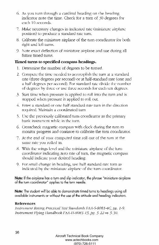
As you turn through a cardinal heading on the headingindicator note the time. Check for a turn of 30 degrees foreach 10 seconds.
Make necessary changes in indicated rate (miniature airplaneposition) to produce a standard rate turn.
Calibrate the miniature airplane of the turn coordinator for bothright and left turns.
Note exact deflection of miniature airplane and use during allfuture timed turns.
Timed turns to specified compass headings.
Determine the number of degrees to be turned.
Compute the time needed to accomplish the turn at a standardrate (three degrees per second) or at half-standard rate (one anda half degrees per second). For standard rate divide the numberof degrees by three or use three seconds for each ten degrees.
Start time when pressure is applied to roll into the turn and isstopped when pressure is applied to roll out.Enter a standard or one-half standard rate turn in the directionrequired. Maintain a coordinated turn
Use the previously calibrated turn coordinator as the primarybank instrument while in the turn.Crosscheck magnetic compass with clock during the turn tomonitor progress and continue to calibrate the turn coordinator.
At the end of your computed time roll out of the turn at thesame rate you rolled in.With the wings level and the miniature airplane of the turncoordinator indicating zero rate of turn, the magnetic compassshould indicate your desired heading.
9. For small change in heading, use half standard-rate turn asindicated by the miniature airplane of the turn coordinator.
Note: If the airplane has a turn and slip indicator, the phrase "miniature airplaneof the turn coordinator" applies to the turn needle.
Note: The student will be able to demonstrate timed turns to headings using allavailable instruments or without the use of the attitude and heading indicators.
ReferencesInstrument Rating Practical Test Standards FAA-S-8081-4C, pg. 1-9.Instrument Flying Handbook FAA-H-8083-15, pg. 5-22 5-30.
J
4
•
36 Aircraft Technical Book Company www.actechbooks.com
(970) 726-5111
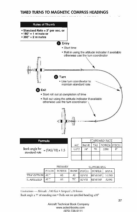
0 Turn
Use turn coordinator tomaintain standard rate
0 Exit
fl
Start roll out at completion of time
Roll out using the attitude indicator if availableotherwise use the turn coordinator
C-C)
0
TIMED TURNS TO MAGNETIC COMPASS HEADINGS
Rules of Thumb
Standard Rate = 3° per sec. or180° = 1 minute or360° = 2 minutes
0 EntryStart time
Roll in using the attitude indicator if availableotherwise use the turn coordinator
Formula
Bank angle for = (TAS/1 0) x 1.5standard rate
PRIMARY
A/C
STANDARD RATE
BANK TAS POWER PITCHC172 14° 90 2200 0°
SUPPORTING
PITCH POWER BANK PITCH POWER BANK
ALT AS AI AI/VSI RPM/MP TC/HI
ALT AS TC AI/VSI RPM/MP AI/HI
TRANSITION
STABILIZED
Limitations — Altitude ± 100 feet • Airspeed ± 10 knotsBank angle ± 5° of standing rate • Rolls out on specified heading ±10°
37Aircraft Technical Book Company
www.actechbooks.com (970) 726-5111
MAGNETIC COMPASS TURNS
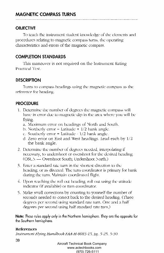
OBJECTIVETo teach the instrument student knowledge of the elements and
procedures relating to magnetic compass turns, the operatingcharacteristics and errors of the magnetic compass.
COMPLETION STANDARDSThis maneuver is not required on the Instrument Rating
Practical Test.
DESCRIPTIONTurns to compass headings using the magnetic compass as the
reference for heading.
PROCEDURE1. Determine the number of degrees the magnetic compass will
have in error due to magnetic dip in the area where you will beflying.
Maximum error on headings of North and South.Northerly error = Latitude + 1/2 bank angle.Southerly error = Latitude - 1/2 bank angle.Zero error on East and West headings. Lead each by 1/2the bank angle.
2. Determine the number of degrees needed, interpolating ifnecessary, to undershoot or overshoot for the desired heading.(OSUN — Overshoot South; Undershoot North.)
Enter a standard rate turn in the shortest direction to theheading, or as directed. The turn coordinator is primary for bankduring the turn. Maintain coordinated flight.
Upon reaching the roll out heading, roll out using the attitudeindicator (if available) or turn coordinator.
5. Make small corrections by counting to yourself the number ofseconds needed to correct back to the desired heading. (Threedegrees per second using standard rate turn. One and a halfdegrees per second using half standard rate turn.)
Note: These rules apply only in the Northern hemisphere. They are the opposite forthe Southern hemisphere.
ReferencesInstrument Flying Handbook FAA-H-8083-15, pg. 5-25, 5-30.
38
Am.
Aircraft Technical Book Company www.actechbooks.com
(970) 726-5111
nPn
PP
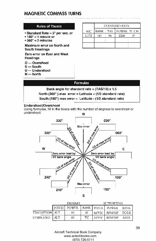
Rules of Thumb
Standard Rate = 3° per sec. or180° = 1 minute or360° = 2 minutes
Maximum error on North andSouth HeadingsZero error on East and WestHeadings
O — OvershootS — SouthU — UndershootN — North
A/C
STANDARD RATE
BANK TAS POWER PITCHC172 14° 90 2200 0°
Formulas
Bank angle for standard rate = (TAS/10) x 1.5North (360°) max error = Latitude + (1/2 standard rate)South (180°) max error = Latitude - (1/2 standard rate)
300° 060°
W E
Max error
330° 030°
Max error
742
Zero error lead by Zero error lead by1 2 bank angle 1 2 bank angle
743
240° 120°
210°
150°
S
PRIMARY
SUPPORTING
39
PITCH POWER BANK PITCH POWER BANK
ALT AS AI AI/VSI RPM/MP TC/HI
ALT AS TC AI/VSI RPM/MP AI/HIn
TRANSITION
STABILIZEDfl
MAGNETIC COMPASS TURNS
Undershoot/OvershootUsing formulas, fill in the boxes with the number of degrees to overshoot orundershoot.
C-Aircraft Technical Book Company
www.actechbooks.com (970) 726-5111
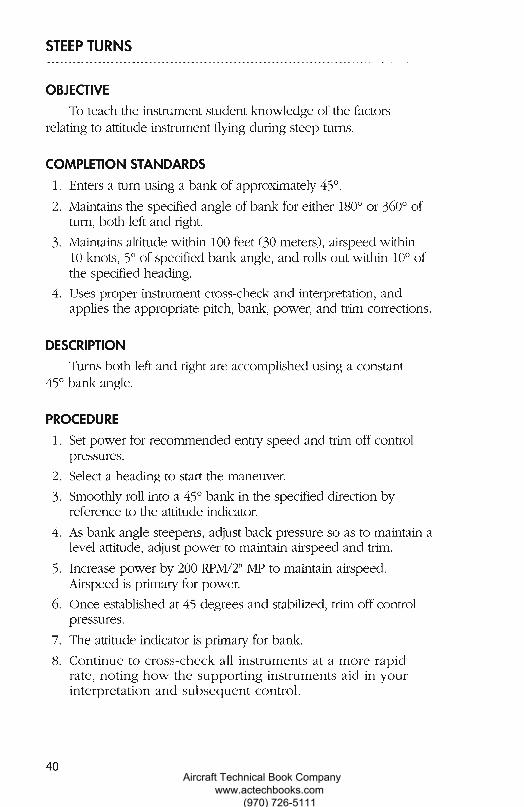
STEEP TURNS
OBJECTIVE
To teach the instrument student knowledge of the factorsrelating to attitude instrument flying during steep turns.
COMPLETION STANDARDS
Enters a turn using a bank of approximately 45°.
Maintains the specified angle of bank for either 180° or 360° ofturn, both left and right.
Maintains altitude within 100 feet (30 meters), airspeed within10 knots, 5° of specified bank angle, and rolls out within 10° ofthe specified heading.Uses proper instrument cross-check and interpretation, andapplies the appropriate pitch, bank, power, and trim corrections.
DESCRIPTION
Turns both left and right are accomplished using a constant45° bank angle. •
.•PROCEDURE
Set power for recommended entry speed and trim off controlpressures. 10
Select a heading to start the maneuver.Smoothly roll into a 45° bank in the specified direction by •reference to the attitude indicator.
•As bank angle steepens, adjust back pressure so as to maintain alevel attitude, adjust power to maintain airspeed and trim.
r.Increase power by 200 RPM/2" MP to maintain airspeed. ••Airspeed is primary for power.
Once established at 45 degrees and stabilized, trim off controlpressures.
The attitude indicator is primary for bank.
Continue to cross-check all instruments at a more rapidrate, noting how the supporting instruments aid in yourinterpretation and subsequent control.
40 Aircraft Technical Book Company www.actechbooks.com
(970) 726-5111
n
n TRANSITION
STABILIZED
PRIMARY SUPPORTING
A/C
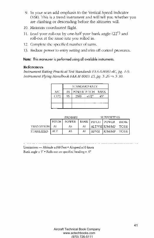
STANDARD RATE
AS POWER PITCH BANKC172 95 2500 +1/2° 45°
PITCH POWER BANK PITCH POWER BANK
AI AS AI ALT/VSI RPM/MP TC/HI
ALT AS AI AI/VSI RPM/MP TC/HI
In your scan add emphasis to the Vertical Speed Indicator(VSI). This is a trend instrument and will tell you whether youare climbing or descending before the altimeter will.Maintain coordinated flight.
Lead your roll-out by one-half your bank angle (22°) androll-out at the same rate you rolled in.Complete the specified number of turns.
13. Reduce power to entry setting and trim off control pressures.
Note: This maneuver is performed using all available instruments.
ReferencesInstrument Rating Practical Test Standards FAA-S-8081-4C, pg. 1-9.Instrument Flying Handbook FAA-H-8083-15, pg. 5-26 5-30.
C0 Limitations — Altitude ± 100 Feet • Airspeed ± 10 knots
Bank angle ± 5° • Rolls out on specified heading ±10°0CCF
n
41Aircraft Technical Book Company
www.actechbooks.com (970) 726-5111
WM.
Am,
RECOVERY FROM UNUSUAL FLIGHT ATTITUDES
OBJECTIVETo teach the instrument student knowledge of the elements
relating to attitude instrument flying during recovery from unusualflight attitudes (both nose-high and nose-low).
COMPLETION STANDARDS1. Uses proper instrument cross-check and interpretation, and applies
the appropriate pitch, bank, and power corrections in the correctsequence to return the aircraft to a stabilized level flight attitude.
DESCRIPTIONWhile simulating emergency instrument conditions, the
instructor/examiner will force the airplane to a critical flightattitude. When instructed, the student will take control of theairplane and recover to straight and level flight.
PROCEDURENote the original heading and altitude.
Two methods of establishing a critical flight attitude may be used.The hooded student is told to look down or up, closehis/her eyes and place the airplane in a standard rate turn.The hooded student is told to remove his/her hands andfeet from the controls, look down or up and close his /hereyes. The instructor/examiner places the airplane into acritical flight attitude.
In either of the above cases, when the airplane is in the criticalflight attitude, the instructor/examiner will clearly tell the studentto open his/her eyes and recover solely by reference to theinstruments.Recognize what type of critical attitude you are experiencing.
Interpret the instruments to produce correct control inputs.Two common situations normally occur.a. Nose high attitude— airspeed low and decreasing.
Add full power.Pitch down to level flight.Level the wings.Return to original heading and altitude.
42 Aircraft Technical Book Company www.actechbooks.com
(970) 726-5111
b. Nose low attitude— airspeed high and increasing.Reduce power as required.Level wings.Pitch up for level flight.Return to original heading and altitude.
The pitch attitude will be approximately level when the airspeedand altimeter needles stop their movement and the verticalspeed indicator reverses its trend.
Recover by prompt, smooth, coordinated control, using propersequence.
Avoid excessive load factors, airspeeds or stalls.
Do not use the attitude indicator until you verify its reliability.The attitude may tumble if its limits are exceeded.
Note: The student will be able to demonstrate recovery from unusual flightattitudes using all available instruments or without the use of the attitude indicator.
Note: Any intervention by the examiner to prevent the aircraft from exceeding anyoperating limitations, or entering an unsafe flight condition, shall be disqualifying.
ReferencesInstrument Rating Practical Test Standards FAA-S-8081-4C, pg. 1-10.Instrument Flying Handbook FAA-H-8083-15, pg. 5-31 5-33.
43Aircraft Technical Book Company
www.actechbooks.com (970) 726-5111