Embed Size (px)
Citation preview
NL6075-00_NL6075-00J020006.DOC
Page 1 of 21
Instrument Design Philosophy
Project No: NL6075-01
Client: Luberef
Project Name: Yanbu Refinery Expansion Project
Jacobs Document No: NL6075-00/J.02/0006
Client Document No: LEP-J0-GS-006
Revision: A
Rev. Issue Date Revision Description Prepared
by Checked
by Discipline
Approved by Project
Approved by
A 15 Aug 2011 For Client Review SCH STK SUG MASL
Project No : NL6075 Instrument Design Philosophy Client : Luberef NL6075-00/J.02/0006, rev. A Project Name : Yanbu Refinery Expansion Project Page 2 of 21
NL6075-00_NL6075-00J020006.DOC
TABLE OF CONTENTS
1. SCOPE ................................................................................................................4
2. DEFINITION OF TERMS .....................................................................................4
2.1. General terms......................................................................................................4
2.2. Abbreviation and Terminology..............................................................................5
3. CODES, REGULATIONS AND STANDARDS .....................................................6
4. KEY DESIGN CONCEPTS ..................................................................................7
4.1. Design Philosophy ...............................................................................................7
4.2. Site ambient conditions........................................................................................8
4.2.1. Temperatures ......................................................................................................8
4.2.1.1. Ambient Air Temperature (dry bulb): ....................................................................8
4.2.1.2. Maximum Design Temperature (dry bulb): ...........................................................8
4.2.1.3. Minimum Design Temperature (dry bulb): ............................................................8
4.3. Humidity and Pressure.........................................................................................8
4.4. Wind ....................................................................................................................9
4.5. Rainfall.................................................................................................................9
4.6. Snow Frost Design...............................................................................................9
4.7. Sandstorm / Sun ..................................................................................................9
4.8. AREA CLASSIFICATION...................................................................................10
5. INSTRUMENT NUMBERING STRUCTURE ......................................................10
6. UNITS OF MEASUREMENT..............................................................................10
7. UTILITIES..........................................................................................................11
8. INSTRUMENT TAPPINGS ................................................................................12
9. INSTRUMENT ROOMS.....................................................................................13
9.1. Instrument rooms...............................................................................................13
9.2. Remote Instrument Enclosures (RIE’s) (4x) .......................................................13
9.3. Operator Shelters (3x)........................................................................................13
10. STANDARD SIGNAL TRANSMISSION .............................................................13
11. INSTRUMENT PROTECTION ...........................................................................14
11.1. General..............................................................................................................14
11.2. INSTRUMENTS LOCATED IN HAZARDOUS AREAS.......................................14
11.3. Material..............................................................................................................15
Project No : NL6075 Instrument Design Philosophy Client : Luberef NL6075-00/J.02/0006, rev. A Project Name : Yanbu Refinery Expansion Project Page 3 of 21
NL6075-00_NL6075-00J020006.DOC
11.4. Instrument under “Pressure Vessel Codes”........................................................15
12. INSTRUMENT CABLES ....................................................................................16
13. Signal segregation .............................................................................................17
13.1. Instrument Air tubing..........................................................................................18
14. Instrument installation ........................................................................................18
15. field instruments.................................................................................................18
16. Instrument selection criteria ...............................................................................19
16.1. Flow Measurements...........................................................................................19
16.1.1. General..............................................................................................................19
16.2. Level Measurements..........................................................................................19
16.2.1. General..............................................................................................................19
16.2.2. Selection Criteria................................................................................................19
16.2.3. Ranges and units...............................................................................................19
16.3. Pressure Measurement......................................................................................20
16.3.1. General..............................................................................................................20
16.3.2. Selection Criteria................................................................................................20
16.3.3. Ranges and Units ..............................................................................................20
16.4. Temperature Measurement General ..................................................................21
16.4.1. Selection Criteria................................................................................................21
16.5. Control Valves ...................................................................................................21
Project No : NL6075 Instrument Design Philosophy Client : Luberef NL6075-00/J.02/0006, rev. A Project Name : Yanbu Refinery Expansion Project Page 4 of 21
NL6075-00_NL6075-00J020006.DOC
1. SCOPE This document provides a basis for design execution of the Instrumentation and Control systems work for the Luberef Refinery Expansion Project at Yanbu, Saudi Arabia. Jacobs will be responsible to provide the FEED deliverables and to compile the ITB package for the following five (8) main clusters:
1) General 2) Lube oil hydro cracking and de-waxing 3) PDA Revamp 4) Hydrogen generation & HRU 5) SRU’s & TGT 6) SWS & Amine 7) Utilities (including flare system, effluent treatment, power generation, etc) 8) Off-sites (including tankage & product loading)
- All data is based on pre-feed documentation and need to be confirmed/updated
2. DEFINITION OF TERMS
2.1. GENERAL TERMS
Company - Where used in this specification shall mean Saudi Aramco Lubricating Oils Company, Luberef.
Contractor - Where used in this specification shall mean Jacobs, handling the feed engineering of the facilities.
Shall - The word 'shall' is to be understood as mandatory. Should - The word 'should' is to be understood as strongly recommended,
however shall only be deviated from with prior written agreement from Purchaser.
May - The word 'may' is to be understood as indicating a possible course of action.
Project No : NL6075 Instrument Design Philosophy Client : Luberef NL6075-00/J.02/0006, rev. A Project Name : Yanbu Refinery Expansion Project Page 5 of 21
NL6075-00_NL6075-00J020006.DOC
2.2. ABBREVIATION AND TERMINOLOGY
CCR Central Control Room DCS Distributed Control System ESD Emergency Shut-down System P&ID Piping and Instrumentation Diagram F&G Fire and Gas Detection RIE Remote Instrument Enclosure I&C Instrumentation and Controls MCC Motor Control Center PLC Programmable Logic Controller
Where one of the terms “normally”, ”generally”, ”usually” or “preferred” is used, it should be understood as a requirement to be followed, unless another valid and acceptable technical solution is achieved and agreed upon.
Project No : NL6075 Instrument Design Philosophy Client : Luberef NL6075-00/J.02/0006, rev. A Project Name : Yanbu Refinery Expansion Project Page 6 of 21
NL6075-00_NL6075-00J020006.DOC
3. CODES, REGULATIONS AND STANDARDS Following standard specifications and codes shall be adhered to during all stages of the contract:
a) Local Law and Regulations b) Saudi Aramco Standards and Specifications
Industry Codes and Standards:
c) American National Standard Institute (ANSI) d) National Electrical Manufacturing Association (NEMA) e) National Fire Protection Association (NFPA) f) National Electric Code (NEC), NFPA 70. g) American Society for Testing and Materials (ASTM) h) International Electro technical Commission (IEC) i) American Petroleum Institute (API) j) Underwriters Laboratories (UL)
In case of conflict amongst standard specifications and codes the following order of priority shall govern:
• Statutory regulations, • Aramco standards (SAES) procedures (SAEP) and material specifications
(SAEMSS) • International codes and standards.
The selection of codes and standards, which are to be used in the plant design, shall be applied so as to satisfy not only the Licensor’s requirements but also with regard to feasibility and economic standpoints. All piping materials for level gauges, relief valves, thermal relief valves, vacuum breakers, tank breather valves shall be in accordance with the relevant piping specification.
Project No : NL6075 Instrument Design Philosophy Client : Luberef NL6075-00/J.02/0006, rev. A Project Name : Yanbu Refinery Expansion Project Page 7 of 21
NL6075-00_NL6075-00J020006.DOC
4. KEY DESIGN CONCEPTS
4.1. DESIGN PHILOSOPHY
The instrument design philosophy shall facilitate operation and maintenance activities as well as installation and construction activities. ( Note: Jacobs will be responsible to provide the FEED deliverables as described under scope) The design shall provide an adequate feature to handle the specified design conditions and all predictable occurrences resulting from process upsets, operational failures, weather or interruption of utilities. The following should be adopted into the design: Control System of the plant shall be a Distributed Control System (DCS) and for Package Units stand alone Programmable Logic Controller (PLC) Safety related trip logic will be carried out in a certified failsafe PLC (ESD) Where possible, standardization of instrumentation should be implemented, as it will result in a smaller variety of items to be purchased, installed and maintained. The standardization shall cover, as a minimum the instrument selection (e.g. sizes, materials, manufacturers etc.), instrument installation and hook-ups (e.g. sizes, connections, tubing and fittings etc.), instrument cables and junction box (e.g. types, sizes etc.) Instruments manufactured to survive the environmental conditions and meet the hazardous area requirements. Use of smart/intelligent instruments, which have remote accessibility and can provide and document useful information for maintenance and operation (e.g. zero point calibration, range calibration, remote diagnostic, etc.)
Project No : NL6075 Instrument Design Philosophy Client : Luberef NL6075-00/J.02/0006, rev. A Project Name : Yanbu Refinery Expansion Project Page 8 of 21
NL6075-00_NL6075-00J020006.DOC
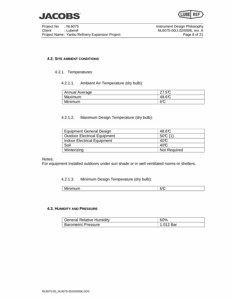
4.2. SITE AMBIENT CONDITIONS
4.2.1. Temperatures
4.2.1.1. Ambient Air Temperature (dry bulb):
Annual Average 27.5°C Maximum 48.6°C Minimum 6°C
4.2.1.2. Maximum Design Temperature (dry bulb):
Equipment General Design 48.6°C Outdoor Electrical Equipment 50°C (1) Indoor Electrical Equipment 40°C Soil 40°C Winterizing Not Required
Notes: For equipment installed outdoors under sun shade or in well ventilated rooms or shelters.
4.2.1.3. Minimum Design Temperature (dry bulb):
Minimum 6°C
4.3. HUMIDITY AND PRESSURE
General Relative Humidity 60% Barometric Pressure 1.012 Bar
Project No : NL6075 Instrument Design Philosophy Client : Luberef NL6075-00/J.02/0006, rev. A Project Name : Yanbu Refinery Expansion Project Page 9 of 21
NL6075-00_NL6075-00J020006.DOC
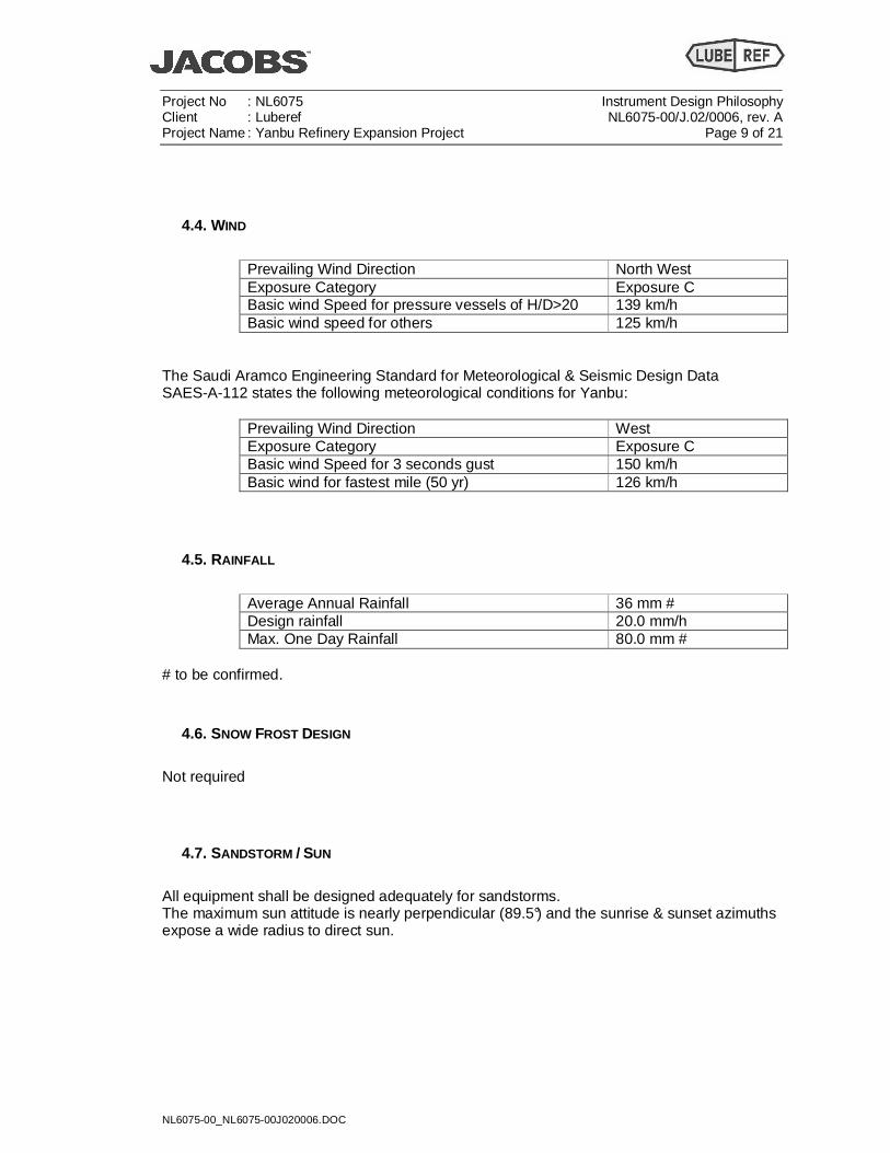
4.4. WIND
Prevailing Wind Direction North West Exposure Category Exposure C Basic wind Speed for pressure vessels of H/D>20 139 km/h Basic wind speed for others 125 km/h
The Saudi Aramco Engineering Standard for Meteorological & Seismic Design Data SAES-A-112 states the following meteorological conditions for Yanbu:
Prevailing Wind Direction West Exposure Category Exposure C Basic wind Speed for 3 seconds gust 150 km/h Basic wind for fastest mile (50 yr) 126 km/h
4.5. RAINFALL
Average Annual Rainfall 36 mm # Design rainfall 20.0 mm/h Max. One Day Rainfall 80.0 mm #
# to be confirmed.
4.6. SNOW FROST DESIGN
Not required
4.7. SANDSTORM / SUN
All equipment shall be designed adequately for sandstorms. The maximum sun attitude is nearly perpendicular (89.5°) and the sunrise & sunset azimuths expose a wide radius to direct sun.
Project No : NL6075 Instrument Design Philosophy Client : Luberef NL6075-00/J.02/0006, rev. A Project Name : Yanbu Refinery Expansion Project Page 10 of 21
NL6075-00_NL6075-00J020006.DOC
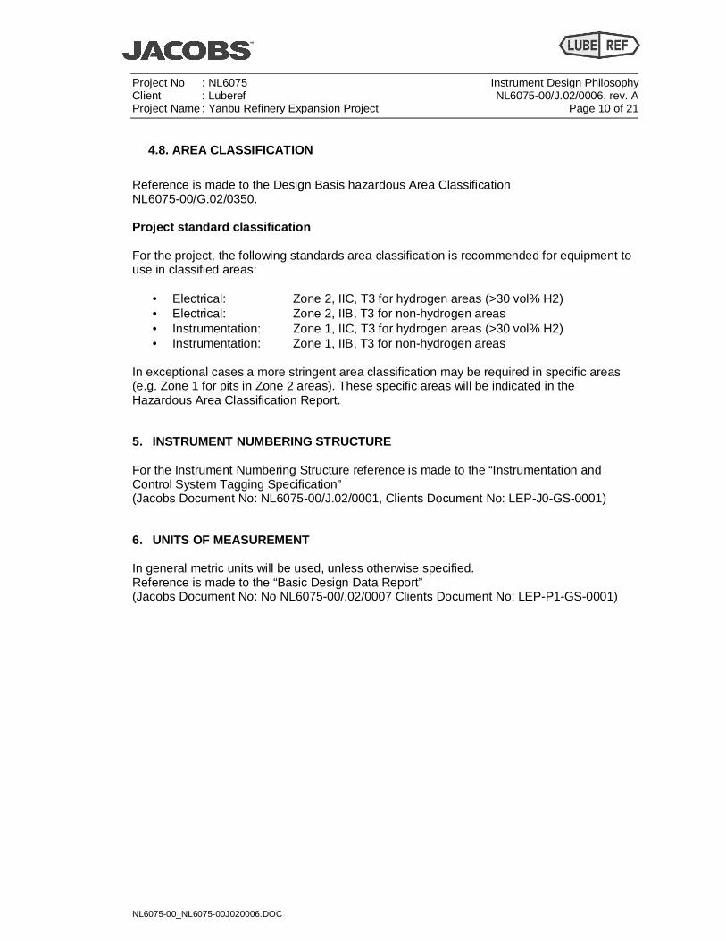
4.8. AREA CLASSIFICATION
Reference is made to the Design Basis hazardous Area Classification NL6075-00/G.02/0350. Project standard classification For the project, the following standards area classification is recommended for equipment to use in classified areas:
• Electrical: Zone 2, IIC, T3 for hydrogen areas (>30 vol% H2) • Electrical: Zone 2, IIB, T3 for non-hydrogen areas • Instrumentation: Zone 1, IIC, T3 for hydrogen areas (>30 vol% H2) • Instrumentation: Zone 1, IIB, T3 for non-hydrogen areas
In exceptional cases a more stringent area classification may be required in specific areas (e.g. Zone 1 for pits in Zone 2 areas). These specific areas will be indicated in the Hazardous Area Classification Report.
5. INSTRUMENT NUMBERING STRUCTURE For the Instrument Numbering Structure reference is made to the “Instrumentation and Control System Tagging Specification” (Jacobs Document No: NL6075-00/J.02/0001, Clients Document No: LEP-J0-GS-0001)
6. UNITS OF MEASUREMENT In general metric units will be used, unless otherwise specified. Reference is made to the “Basic Design Data Report” (Jacobs Document No: No NL6075-00/.02/0007 Clients Document No: LEP-P1-GS-0001)
Project No : NL6075 Instrument Design Philosophy Client : Luberef NL6075-00/J.02/0006, rev. A Project Name : Yanbu Refinery Expansion Project Page 11 of 21
NL6075-00_NL6075-00J020006.DOC
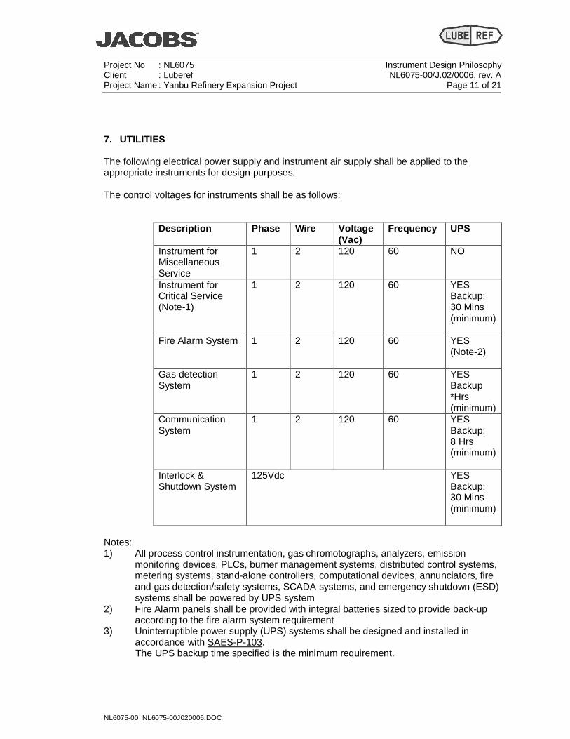
7. UTILITIES The following electrical power supply and instrument air supply shall be applied to the appropriate instruments for design purposes. The control voltages for instruments shall be as follows:
Description Phase Wire Voltage (Vac)
Frequency UPS
Instrument for Miscellaneous Service
1 2 120 60 NO
Instrument for Critical Service (Note-1)
1 2 120 60 YES Backup: 30 Mins (minimum)
Fire Alarm System 1 2 120 60 YES (Note-2)
Gas detection System
1 2 120 60 YES Backup *Hrs (minimum)
Communication System
1 2 120 60 YES Backup: 8 Hrs (minimum)
Interlock & Shutdown System
125Vdc YES Backup: 30 Mins (minimum)
Notes: 1) All process control instrumentation, gas chromotographs, analyzers, emission
monitoring devices, PLCs, burner management systems, distributed control systems, metering systems, stand-alone controllers, computational devices, annunciators, fire and gas detection/safety systems, SCADA systems, and emergency shutdown (ESD) systems shall be powered by UPS system
2) Fire Alarm panels shall be provided with integral batteries sized to provide back-up according to the fire alarm system requirement
3) Uninterruptible power supply (UPS) systems shall be designed and installed in accordance with SAES-P-103.
The UPS backup time specified is the minimum requirement.
Project No : NL6075 Instrument Design Philosophy Client : Luberef NL6075-00/J.02/0006, rev. A Project Name : Yanbu Refinery Expansion Project Page 12 of 21
NL6075-00_NL6075-00J020006.DOC
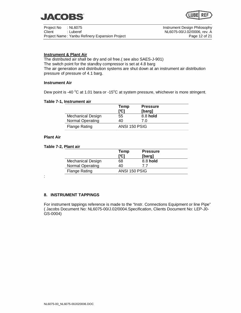
Instrument & Plant Air The distributed air shall be dry and oil free.( see also SAES-J-901) The switch point for the standby compressor is set at 4.8 barg The air generation and distribution systems are shut down at an instrument air distribution pressure of pressure of 4.1 barg. Instrument Air Dew point is -40 oC at 1.01 bara or -15oC at system pressure, whichever is more stringent. Table 7-1, Instrument air
Temp [°C]
Pressure [barg]
Mechanical Design 55 8.8 hold Normal Operating 40 7.0 Flange Rating ANSI 150 PSIG
Plant Air Table 7-2, Plant air
Temp [°C]
Pressure [barg]
Mechanical Design 68 8.8 hold Normal Operating 40 7.7 Flange Rating ANSI 150 PSIG
:
8. INSTRUMENT TAPPINGS For instrument tappings reference is made to the “Instr. Connections Equipment or line Pipe” ( Jacobs Document No: NL6075-00/J.02/0004.Specification, Clients Document No: LEP-J0-GS-0004)
Project No : NL6075 Instrument Design Philosophy Client : Luberef NL6075-00/J.02/0006, rev. A Project Name : Yanbu Refinery Expansion Project Page 13 of 21
NL6075-00_NL6075-00J020006.DOC
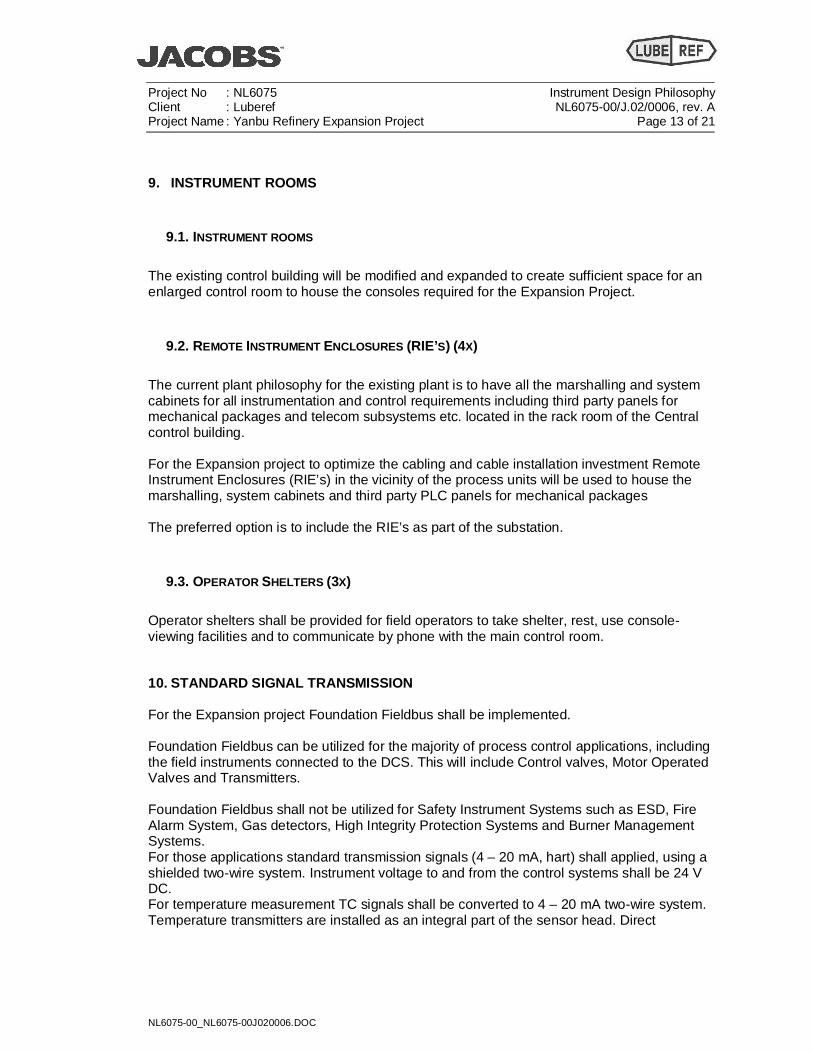
9. INSTRUMENT ROOMS
9.1. INSTRUMENT ROOMS
The existing control building will be modified and expanded to create sufficient space for an enlarged control room to house the consoles required for the Expansion Project.
9.2. REMOTE INSTRUMENT ENCLOSURES (RIE’S) (4X)
The current plant philosophy for the existing plant is to have all the marshalling and system cabinets for all instrumentation and control requirements including third party panels for mechanical packages and telecom subsystems etc. located in the rack room of the Central control building. For the Expansion project to optimize the cabling and cable installation investment Remote Instrument Enclosures (RIE’s) in the vicinity of the process units will be used to house the marshalling, system cabinets and third party PLC panels for mechanical packages The preferred option is to include the RIE’s as part of the substation.
9.3. OPERATOR SHELTERS (3X)
Operator shelters shall be provided for field operators to take shelter, rest, use console-viewing facilities and to communicate by phone with the main control room.
10. STANDARD SIGNAL TRANSMISSION For the Expansion project Foundation Fieldbus shall be implemented. Foundation Fieldbus can be utilized for the majority of process control applications, including the field instruments connected to the DCS. This will include Control valves, Motor Operated Valves and Transmitters. Foundation Fieldbus shall not be utilized for Safety Instrument Systems such as ESD, Fire Alarm System, Gas detectors, High Integrity Protection Systems and Burner Management Systems. For those applications standard transmission signals (4 – 20 mA, hart) shall applied, using a shielded two-wire system. Instrument voltage to and from the control systems shall be 24 V DC. For temperature measurement TC signals shall be converted to 4 – 20 mA two-wire system. Temperature transmitters are installed as an integral part of the sensor head. Direct
Project No : NL6075 Instrument Design Philosophy Client : Luberef NL6075-00/J.02/0006, rev. A Project Name : Yanbu Refinery Expansion Project Page 14 of 21
NL6075-00_NL6075-00J020006.DOC
connection of TC signals to DCS and PLC should not be considered, only in very special cases it will be allowed (i.e. rotating machines etc.) For the PDA upgrade the instrumentation shall be the same as the existing and employ 4 – 20 mA signal transmission
11. INSTRUMENT PROTECTION The scope for Jacobs is to provide the FEED deliverables, to compile the ITB package and to make only a preliminary type selection ( to be verified and confirmed by the selected detailed engineering contractor) and does not include the actual specification of the field instrumentation. Therefore only reference is made to the applicable codes regulations and standards (as referred to under 3).
11.1. GENERAL
All field instruments, outdoor panels and its accessories shall be weatherproof (e.g. watertight, dustproof), corrosion resistant and suitable for installation in a dusty environment. The equipment shall be able to operate in the ambient conditions expected without any significant reduction in the instrument life expectancy. As a minimum the field instruments, outdoor panels and its accessories shall have an ingress protection of IP65 in accordance with EN 60529, unless otherwise specified. Wherever required instrument protective housing shall be used to protect the instrument against the environmental condition. adhered to.
11.2. INSTRUMENTS LOCATED IN HAZARDOUS AREAS
All instrumentation equipment, materials and installation methods shall comply with and fully satisfy the requirements for the area classification identified in the Project Area Classification drawings. The existing philosophy is to have non incendive or explosion proof for zone 2 and zone 1 areas respectively. For new facilities associated with the Expansion Project in general the method of protection used shall follow Saudi Aramco standards refer to SAES-J-902 and SAES-J-903 and Jacobs document .NL6075/G.02/0350
Project No : NL6075 Instrument Design Philosophy Client : Luberef NL6075-00/J.02/0006, rev. A Project Name : Yanbu Refinery Expansion Project Page 15 of 21
NL6075-00_NL6075-00J020006.DOC
11.3. MATERIAL
Generally the use of asbestos in any form is prohibited. The selection of materials should take into account the process fluid operating conditions (temperature, pressure, etc.) For general construction materials the local ambient conditions must be considered. Instrument parts in direct contact with instrument air should normally be 316L stainless steel, or for instruments the manufacturers standard when this is thought to be acceptable. The materials for all wetted parts of field instruments (e.g. measuring elements of pressure transmitter etc.) shall be 316L stainless steel as a minimum, unless otherwise required due to process considerations. Materials for wetted parts of in-line instruments (e.g. valves, turbine meters etc.) shall be either in accordance with the piping specification or, when not available, a higher standard. As a minimum all instruments in contact with the process shall be delivered with EN10204-3.1B material certificate. Any additional requirement will be called out on the technical data sheets.
11.4. INSTRUMENT UNDER “P RESSURE VESSEL CODES”
The following instruments shall be constructed and tested in accordance with the specification for welded or non-welded pressure vessels Auxiliary pressure vessels (e.g. volume tanks, instrument air receiver etc.) Chambers for float or displacement type level instruments, level switches, gauge glasses, magnetic level gauges etc. In-line instruments /components such as variable area meters, turbine meters, filters etc. Control valves, on-off valves, safety valves etc.
Project No : NL6075 Instrument Design Philosophy Client : Luberef NL6075-00/J.02/0006, rev. A Project Name : Yanbu Refinery Expansion Project Page 16 of 21
NL6075-00_NL6075-00J020006.DOC
12. INSTRUMENT CABLES The scope for Jacobs is to provide the FEED deliverables; to compile the ITB package does not include the selection/specification of instrumentation cable. Therefore only reference is made the applicable codes regulations and standards (as referred to under 3). Specialy: -18-SAMSS-625 Fibre Optical cable - 34-SAMSS-913 Instrumentation and thermocouples cable - SAES-J-902 Electrical Systems for Instrumentation - SAES-J-904 Foundation TM fieldbus (FF) systems
Project No : NL6075 Instrument Design Philosophy Client : Luberef NL6075-00/J.02/0006, rev. A Project Name : Yanbu Refinery Expansion Project Page 17 of 21
NL6075-00_NL6075-00J020006.DOC
13. Signal segregation Reference is made to SAES-J-902 Signal wiring (instrumentation cable) shall be categorized with noise susceptibility levels (NSL) of ‘1’ or ‘2’. Commentary Note: Noise susceptibility level ratings and separation tables are derived from IEEE 518 Guide for the Installation of Electrical Equipment to Minimize Electrical Noise Inputs to Controllers from External Sources. The IEEE 518 standard defines three (3) noise susceptibility levels for instrumentation signals, however due to the signal levels commonly used in Saudi Aramco's facilities it was deemed that two (2) noise susceptibility levels were adequate. Level 1 – High to Medium Susceptibility: Analog signals of less than 50 V and discrete instrument signals of less than 30 V.
Signal Types a) Foundation Fieldbus b) 4-20 mA and 4-20 mA with HART c) RTD d) Thermocouple e) mV/Pulse f) Discrete input & output signals, e.g., pressure switches, valve position limit
switches, indicating lights, relays, solenoids, etc. g) All wiring connected to components associated with sensitive analog hardware
(e.g., strain gauge) h) Copper data links (RS-232 or 485)
Level 2 – Low Susceptibility: Switching signals greater than 30 V, analog signals greater than 50 V, and 120-240 AC feeders less than 20 amps.
Signal Types a) Discrete input & output DC signals, e.g., pressure switches, valve position limit
switches, indicating lights, relays, solenoids, etc. b) Discrete input & output AC signals, e.g., pressure switches, valve position limit
switches, indicating lights, relays, solenoids, etc. c) 120-240 AC feeders of less than 20 amps.
Level 3 – Power: AC and DC buses of 0-1000 V with currents of 20-800 amps. Commentary Note: Power: is shown for the spacing requirements between 'instrumentation cable' and 'electrical cable'. (see SAES-J-902)
Project No : NL6075 Instrument Design Philosophy Client : Luberef NL6075-00/J.02/0006, rev. A Project Name : Yanbu Refinery Expansion Project Page 18 of 21
NL6075-00_NL6075-00J020006.DOC
13.1. INSTRUMENT AIR TUBING
Reference is made to SAMS-821 paragraph 7 Instrument air tubing shall be 316L stainless steel. The tubing shall be seamless fully annealed stainless steel suitable for bending. The fittings shall be 316L stainless steel and dual ferrule compression type. All fittings, unions, etc. shall normally be with tapered threads (NPT) unless otherwise required. The following tubing sizes shall be used where applicable fir instrument air: - Normal use - ½” O.D. with 0.065” (≈ 1.5 mm) wall thickness - Special use - ¼” O.D. with 0.035” (≈ 1.0 mm) wall thickness (special instr., bulkhead fittings, etc.) Wherever required, flexible local tubing shall be stainless steel corrugated. Bulkhead type fittings shall be used for all pneumatic connections to local panels/housings. For the instrument air tubing inside closed panels/housings it will be possible to use plastic tubing and fittings – design min 10 barg.
14. Instrument installation The scope for Jacobs is to provide the FEED deliverables, to compile the ITB package and to make only a preliminary type selection (to be verified and confirmed by the selected detailed engineering contractor) and does not include the actual installation details of the field instrumentation. Therefore only reference is made the applicable codes regulations and standards (as referred to under 3).
15. field instruments The scope for Jacobs is to provide the FEED deliverables, to compile the ITB package and to make only a preliminary type selection (to be verified and confirmed by the selected detailed engineering contractor) and does not include the actual specification of the field instrumentation. Therefore only reference is made to selection criteria (as referred to under 18) and the applicable codes regulations and standards (as referred to under 3).
Project No : NL6075 Instrument Design Philosophy Client : Luberef NL6075-00/J.02/0006, rev. A Project Name : Yanbu Refinery Expansion Project Page 19 of 21
NL6075-00_NL6075-00J020006.DOC
16. Instrument selection criteria
16.1. FLOW MEASUREMENTS
Reference is made to SAES-J-100
16.1.1. General For flow measurements preferably a primary element (a concentric circular orifice plate with flange tappings) associated with an electronic differential pressure transmitter (Smart) shall be used. Where a low pressure drop is required a suitable flow element shall be used as per requirement.
16.2. LEVEL MEASUREMENTS
Reference is made to SAES-J-300
16.2.1. General Guided Wave Radar (GWR) is the preferred liquid level and liquid-liquid interface level measurement technology – for both process and ESD applications. Other level measurement technology may be used if GWR is not suited to the application.
16.2.2. Selection Criteria The selection of a level measurement shall correspond to the required accuracy, measuring range, availability and measuring duty. Where possible, level measurement shall be performed by differential pressure measurement, in accordance with the following criteria: The use of Guided Wave Radar (GWR) is the preferred Instruments to be selected to allow easy replacement and maintenance during operation In particular cases for certain specific operating conditions other measurement principles may be used.
16.2.3. Ranges and units For all level measurement the range shall be 0 to 100%. For dP level measurement no fixed nozzle distance is required.
Project No : NL6075 Instrument Design Philosophy Client : Luberef NL6075-00/J.02/0006, rev. A Project Name : Yanbu Refinery Expansion Project Page 20 of 21
NL6075-00_NL6075-00J020006.DOC
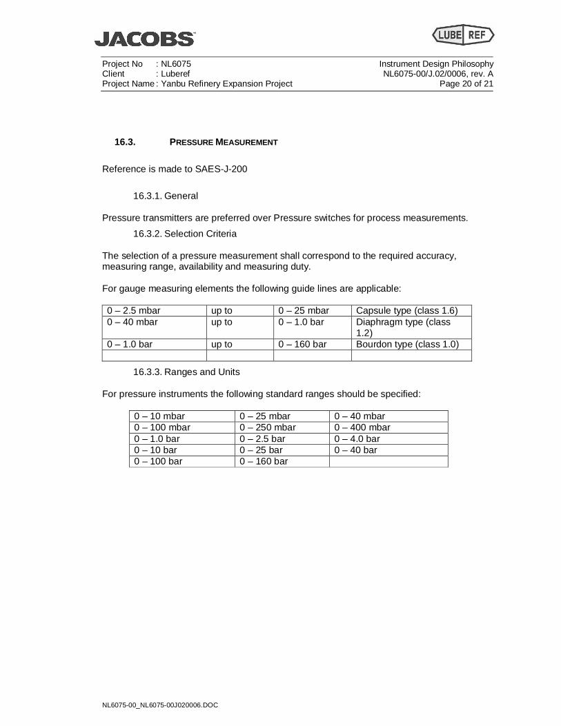
16.3. PRESSURE MEASUREMENT
Reference is made to SAES-J-200
16.3.1. General Pressure transmitters are preferred over Pressure switches for process measurements.
16.3.2. Selection Criteria The selection of a pressure measurement shall correspond to the required accuracy, measuring range, availability and measuring duty. For gauge measuring elements the following guide lines are applicable: 0 – 2.5 mbar up to 0 – 25 mbar Capsule type (class 1.6) 0 – 40 mbar up to 0 – 1.0 bar Diaphragm type (class
1.2) 0 – 1.0 bar up to 0 – 160 bar Bourdon type (class 1.0)
16.3.3. Ranges and Units For pressure instruments the following standard ranges should be specified:
0 – 10 mbar 0 – 25 mbar 0 – 40 mbar 0 – 100 mbar 0 – 250 mbar 0 – 400 mbar 0 – 1.0 bar 0 – 2.5 bar 0 – 4.0 bar 0 – 10 bar 0 – 25 bar 0 – 40 bar 0 – 100 bar 0 – 160 bar
Project No : NL6075 Instrument Design Philosophy Client : Luberef NL6075-00/J.02/0006, rev. A Project Name : Yanbu Refinery Expansion Project Page 21 of 21
NL6075-00_NL6075-00J020006.DOC
16.4. TEMPERATURE MEASUREMENT GENERAL
Reference is made to SAES-J-400
16.4.1. Selection Criteria The selection of a temperature measurement shall correspond with the required accuracy, measuring range, availability and measuring duty. Bimetallic thermometers shall be used for local indication. Unless other wise specified, for remote temperature measurement RTD’s shall be used with head mounted transmitters. Note: RTDs are preferred over thermocouples for most temperature sensing applications within Saudi Aramco. RTDs may be used for measuring temperatures up to approximately 800°C (1500°F). Above this temperature, thermocouples sho uld be used.
16.5. CONTROL VALVES
Reference is made to SAES-J-700 9 During the feed phase and for the 10% estimate control valves shall be sized one size smaller than the line size. For control valves in the following special services a preliminary calculation shall be made: High pressure (exceeding 50 Barg. High differential pressure Two phase flow