Embed Size (px)
Citation preview

Istruzioni per l’uso dellaTaglierina elettrica
Operating InstructionsTile cutting machine
Mode d’emploiMachine à découper les carreaux
BedienungsanleitungFliesenschneidmaschine
Manual de instruccionesMàquina para cortar baldosas
I
GB
F
D
E
CLA
SS
Instrukcje użytkowania piły do budowy
PL
GebruiksaanwijzingTegelsnijmachine
Mode d’emploiMachine à découper les carreaux
Operating InstructionsTile cutting machine
BedienungsanleitungFliesenschneidmaschine
BetjeningsvejledningFlisesavemaskine
Manual de instruccionesMàquina para cortar baldosas
NL
F
GB
D
DK
E
C 2067C 2090


DIC
HIA
RA
ZIO
NE
CE
DI C
ON
FOR
MIT
ÁEC
DEC
LAR
ATIO
NO
F C
ON
FOR
MIT
YD
ECLA
RAT
ION
CE
DE
CO
NFO
RM
ITE
EG-
KO
NFO
RM
ITÄ
TSER
KLÄ
RU
NG
Il so
ttosc
ritto
, ra
ppre
sent
ante
il
segu
ente
co
stru
ttore
The
unde
rsig
ned,
re
pres
entin
g th
e fo
llow
ing
man
ufac
ture
rLe
sou
ssig
né, r
epré
sent
ant l
e co
nstru
cteu
r ci
-apr
ésD
er U
nter
zeic
hner
, der
den
nac
hste
hend
en
Her
stel
ler v
ertri
tt
BAT
TIPA
V S.
R.L
.Z.
i. 2
- Via
Cav
ator
ta, 6
/1 -
4801
0 C
otig
nola
(R
a) I
TALY
dich
iara
qui
di s
egui
to c
he la
tagl
ierin
a pe
r ce
ram
ica,
mon
ocot
tura
, mar
mo
here
with
dec
lare
s th
at th
e cu
tting
mac
hine
fo
r cer
amic
, sin
gle-
firin
g ce
ram
ic, m
arbl
edé
clare
par
la p
rése
nte
que
le c
oupe
-car
reau
x po
ur c
éram
ique
, mon
ocui
sson
, mar
bre
erkl
ärt h
ierm
it, d
aß d
ie S
chne
idem
asch
ine
für
Ker
amik
flies
en,
einf
ach
gebr
annt
en
Flie
sen,
Mar
mor
M
od. 6
5670
M
od. 6
5671
M
od. 6
5900
M
od. 6
5901
23
0V ~
50
Hz
100
0 W
23
0V ~
50
Hz
100
0 W
23
0V ~
50
Hz
100
0 W
23
0V ~
50
Hz
100
0 W
S
3 50
% 3
0s/3
0s
S3
50%
30s
/30s
S
3 50
% 3
0s/3
0s
S3
50%
30s
/30s
28
00 m
in-1
28
00 m
in-1
28
00 m
in-1
28
00 m
in-1
M
OTO
R C
LAS
S F
M
OTO
R C
LAS
S F
M
OTO
R C
LAS
S F
M
OTO
R C
LAS
S F
risul
ta in
con
form
ità a
qua
nto
prev
isto
dal
le
segu
enti
dire
ttive
com
unita
rie:
DIR
ETT
IVA
2006
/42/
CE
, D
IRE
TTIV
A 20
06/9
5/C
E,
DIR
ETT
IVA
2004
/108
/CE
, D
IRE
TTIV
A 20
02/9
6/C
E.
e ch
e so
no s
tate
app
licat
e tu
tte le
nor
me
e/o
spec
ifich
e te
cnic
he in
dica
te.
is in
con
form
ity w
ith th
e pr
ovis
ions
of t
he
follo
win
g E
C d
irect
ives
: 20
06/4
2, 2
006/
95, 2
004/
108,
200
2/96
and
that
the
sta
ndar
ds a
nd/o
r te
chni
cal
spec
ifica
tions
re
fere
nced
ha
ve
been
ap
plie
d.
est
conf
orm
e au
x di
spos
ition
s de
s di
rect
ives
CE
sui
vant
es:
DIR
EC
TIV
E
2006
/42/
CE
, D
IRE
CTI
VE
20
06/9
5/C
E,
DIR
EC
TIV
E
2004
/108
/CE
, D
IRE
CTI
VE
200
2/96
/CE
.et
qu
e le
s no
rmes
et
/ou
spéc
ifica
tions
te
chni
ques
ont
été
app
liqué
es.
in Ü
bere
inst
imm
ung
ist m
it den
Bes
timm
unge
n de
r na
chst
ehen
den
EG-R
ichtlin
ien:
EG
R
ICH
TLIN
IE
2006
/42,
EG
R
ICH
TLIN
IE
2006
/95,
EG
R
ICH
TLIN
IE
2004
/108
, EG
R
ICH
TLIN
IE 2
002/
96.
und
daß
die
Nor
men
und
/ode
r te
chni
sche
n Sp
ezifik
atio
nen,
zur
Anw
endu
ng g
elan
gt s
ind.
EN IS
O 1
2100
-1, E
N IS
O 1
2100
-2, E
N IS
O 1
4121
-1, E
N 6
1029
-1, E
N 6
0335
-1, E
N 6
0335
-2-4
1, E
N 1
2418
, IEC
102
9-2-
7,EN
550
14-1
, EN
550
14-2
, EN
610
006-
1, E
N 6
1000
6-3,
EN
610
006-
4-2,
EN
610
006-
4-4,
EN
610
006-
4-5,
EN
610
006-
4-6
e au
toriz
zo
Zoli
Alb
erto
a
cost
ituire
il
fasc
icol
o te
cnic
oan
d Zo
li A
lber
to is
aut
horiz
ed t
o co
mpi
le
the
tech
nica
l file
et A
lber
to Z
oli e
st a
utor
isé
à co
nstit
uer
le
doss
ier t
echn
ique
und
Albe
rto
Zoli
ist
bere
chtig
t, di
e te
chni
sche
n U
nter
lage
n zu
sam
men
zust
elle
n
Dat
a di
cos
truzi
one
N°
di S
erie
:D
ate
of m
anuf
actu
re
Ser
ies
N.
Dat
e de
fabr
icat
ion
N°
de s
érie
Pro
dukt
ions
datu
m
Ser
ienn
umm
er
Dire
ttore
Gen
eral
eC
laud
io T
ondi
niG
ener
al M
anag
erC
laud
io T
ondi
ni
Le D
irect
eur G
énér
alC
laud
io T
ondi
ni
Der
Gen
eral
dire
ktor
Cla
udio
Ton
dini
DEC
LAR
AC
IÓN
DE
CO
NFO
RM
IDA
D C
ED
EKLA
RA
CJA
ZG
OD
NO
OC
I WE
EF O
VERE
NSST
EMM
ELSE
SERK
LÆRI
NGD
ECLA
RA
ÇÃ
O C
ED
E C
ON
FOR
MID
AD
E
El a
bajo
firm
ante
, en
repr
esen
taci
ón d
eN
iżej
pod
pisa
ny, r
epre
zent
ując
y fir
mę:
Und
erte
gned
e,
der
repr
æse
nter
er
følg
ende
fabr
ikan
tO
aba
ixo
assi
nado
, em
rep
rese
ntaç
ão d
o se
guin
te fa
bric
ante
BAT
TIPA
V S.
R.L
.Z.
i. 2
- Via
Cav
ator
ta, 6
/1 -
4801
0 C
otig
nola
(R
a) I
TALY
decl
ara
que
la c
orta
dora
par
a ce
rám
ica,
m
onoc
occi
ón, m
árm
oni
niej
szym
de
klar
uje,
że
pr
zeci
nark
a ta
rczo
wa
do c
eram
iki
erklæ
rer
herm
ed
at
Skæ
rem
askin
en
for
kera
mik,
enk
eltb
rænd
t, m
arm
orpe
la p
rese
nte
decl
ara
que
a co
rtado
ra
para
cer
âmic
a, m
ono-
coze
dura
, már
mor
e
M
od. 6
5670
M
od. 6
5671
M
od. 6
5900
M
od. 6
5901
23
0V ~
50
Hz
100
0 W
23
0V ~
50
Hz
100
0 W
23
0V ~
50
Hz
100
0 W
23
0V ~
50
Hz
100
0 W
S
3 50
% 3
0s/3
0s
S3
50%
30s
/30s
S
3 50
% 3
0s/3
0s
S3
50%
30s
/30s
28
00 m
in-1
28
00 m
in-1
28
00 m
in-1
28
00 m
in-1
M
OTO
R C
LAS
S F
M
OTO
R C
LAS
S F
M
OTO
R C
LAS
S F
M
OTO
R C
LAS
S F
es c
onfo
rme
con
las
disp
osic
ione
s de
las
sigu
ient
es d
irect
ivas
CE
:D
IRE
CTI
VA
2006
/42/
CE
, D
IRE
CTI
VA
2006
/95/
CE
, D
IRE
CTI
VA
2004
/108
/CE
, D
IRE
CTI
VA 2
002/
96/C
Ey
que
se h
an a
plic
ado
las
norm
as y
/o
espe
cific
acio
nes
técn
icas
refe
renc
iada
s.
speł
nia
wym
agan
ia
nast
ępuj
ącyc
h dy
rekt
yw W
spól
noty
Eur
opej
skie
j:20
06/4
2/C
E,
2006
/95/
CE
, 20
04/1
08/C
E,
2002
/96/
CE
oraz
, że
za
stos
owan
o no
rmy
zhar
mon
izow
ane.
er
i ov
eren
sste
mm
else
m
ed
best
emm
else
rne
i føl
gend
e E
F di
rekt
iver
:E
F di
rekt
iv 2
006/
42,
EF
dire
ktiv
200
6/95
, E
F di
rekt
iv 2
004/
108,
EF
dire
ktiv
200
2/96
.og
at
al
le
stan
dard
er
og/e
ller
tekn
iske
sp
ecifi
katio
ner e
r ble
vet a
nven
dt.
está
em
con
form
idad
e co
m o
est
abel
ecid
o na
s se
guin
tes
dire
ctiva
s co
mun
itária
s:D
IRET
IVA
2006
/42/
CE,
DIR
ETIV
A 20
06/9
5/C
E,
DIR
ETIV
A 20
04/1
08/C
E,
DIR
ETIV
A 20
02/9
6/C
Ee
que
fora
m
aplic
adas
as
no
rmas
e/
ou
espe
cifica
ções
técn
icas
refe
renc
iada
s.
EN IS
O 1
2100
-1, E
N IS
O 1
2100
-2, E
N IS
O 1
4121
-1, E
N 6
1029
-1, E
N 6
0335
-1, E
N 6
0335
-2-4
1, E
N 1
2418
, IEC
102
9-2-
7,EN
550
14-1
, EN
550
14-2
, EN
610
006-
1, E
N 6
1000
6-3,
EN
610
006-
4-2,
EN
610
006-
4-4,
EN
610
006-
4-5,
EN
610
006-
4-6
y A
lber
to
Zoli
tiene
au
toriz
ació
n pa
ra
elab
orar
el e
xped
ient
e té
cnic
oi
Alb
erto
Zo
li je
st
upow
ażni
ona
do
przy
goto
wan
ia d
okum
enta
cji t
echn
iczn
ejog
Alb
erto
Zol
i bem
yndi
ges
til a
t uda
rbej
de
det t
ekni
ske
doss
ier
e Al
berto
Zol
i est
á au
toriz
ado
a co
mpi
lar
o pr
oces
so té
cnic
o
Fech
a de
fabr
icac
iòn
N°
de s
erie
:D
ata
prod
ukcj
i N
umer
ser
yjny
.Fr
emst
illin
gsda
to
Ser
ie N
.:D
ata
de p
rodu
ção
N°
de s
erie
Dire
ctor
Gen
eral
Cla
udio
Ton
dini
Dyr
ekto
r nac
zeln
yC
laud
io T
ondi
niD
irekt
ørC
laud
io T
ondi
niD
ireto
r Ger
alC
laud
io T
ondi
ni

22
ITGB CAUTION!
THE MACHINE IS NOT INTENDED FOR USE IN AN EXPLOSIVE ENVIRONMENT
CAUTION!
ALWAYS USE INDIVIDUAL PROTECTION DEVICES TO REDUCE THE RISKS CAUSED BY WORK. NEVER START THE MACHINE WHEN THE CUTTING TOOL IS MOVING; WAIT FOR IT TO STOP.
Warning! When using electric tools, following safety precautions should always be followed to reduce the risk of fire, electric shock and personal injuries. Read and follow all these instructions before attempting to operate this product and save them with care!
SAVE THESE INSTRUCTIONS WITH CARE.
Keep your work area perfectly clean- Cluttered areas invite injuries.
Consider work area environment- Don’t expose tools to rain. - Don’t use tools in damp or wet locations. Keep
work area well lit. - Don’t use tools in presence of flammable liquids
or gases.
Guard against electric shocks- Prevent body contact with grounded surfaces.
Keep children away!- Do not let third parties contact tool or extension
cord. All visitors should be kept away from work area.
Store your tools in a save place - When not in use, tools should be stored in dry
and save places, out of the reach of children.
Don’t force tool- It will function better and in a safer way at the
rate for which it was intended.
Use the right tool- Don’t use low duty tools or accessories to do
the job of a heavy-duty tools. Don’t use tools for purposes not intended.
“TRANSLATE OF THE ORIGINAL INSTRUCTION”
1. Purpose of this Manual
This manual is an integral part of the machine.It was produced by BATTIPAV S.R.L. to provide those authorised to work with the machine with the information required for its foreseeable lifespan.Before starting to use this machine read the safety chapter carefully.Each machine is subjected to a series of tests and carefully checked before leaving our factory.BATTIPAV S.R.L. is constantly striving to develop their machines and therefore reserves the right to make any change without prior notice. Therefore, no claims may be made on the basis of the data and illustrations contained in this manual.
2. Safety information
• The manufacturer accepts no responsibility where the CLASS cutter is used with any tools other than those specified in the “RECOMMENDED USE” paragraph.
DO NOT USE WOODEN DISCS.
DO NOT USE DRY-CUTTING DISCS.
• CLASS is made to operate exclusively under the conditions indicated under “TYPE OF OPERATION ALLOWED”, in the “TECHNICAL DATA” paragraph.
• During cutting operations, allow the machine to rest as indicated.
• CLASS is not made for use with a continuous load.
CAUTION!
DO NOT USE DIAMOND TIPPED DISCS OF LOW QUALITY OR THAT ARE NOT SUITABLE FOR THE SPECIFIC USE FOR WHICH THE MANUFACTURER SUPPLIED THEM. THE USE OF POOR QUALITY DISCS CAN HARM THE OPERATOR AND DAMAGE THE MACHINE, AS WELL AS SIGNIFICANTLY SLOWING THE WORK.
23
ITGBindicated elsewhere in this instruction manual.
- Have defective switches replaced by an authorised Service Centre.
- Do not use tool if its switch cannot be turned on or off.
Warning- For your personal safety use only accessories
recommended in this instruction manual or in the relevant catalogues The use of any other accessory or attachment other than those recommended in this instruction manual or in the relevant catalogue may present a risk of personal injury.
Have tools repaired by qualified personnel - This electric appliance is in accordance with
the safety rules in force. Only qualified experts may carry out repairing of electric appliances otherwise it may cause considerable danger for the user.
3. Manufacturer and machine The nameplate shown is fitted directly on the machine. It indicates all the references and information necessary for safe operation.
TYPE N°art.
V~ PHz A
min-1 cl.is
Ø max Ø int.
µF IP YEAR
Made by: BATTIPAV SRLVia Cavatorta, 6/1 Z.i. 2 - 48033 - Cotignola (RA) ITALY
A B CD E F G
HO
QR
S
T
PI L M N
U
1
Dress properly- Rubber gloves and non-skid footwear are
recommended when working outdoors. Wear protective hair covering to contain long hair. Use safety glasses.
- Use a mask if working operations are dusty.
Don’t abuse cord- Never carry tool by cord or yank it to disconnect
it from socket. - Keep cord from heat, oil and sharp edges.
Avoid unsteady positions- Be sure to work in a safe and balanced position.
Maintain tools with care- Keep tools sharp and clean for better and safer
performance. - Follow all maintenance advice and instructions
to replace accessories subject to wear. Inspect tool cords periodically and, if damaged, have them repaired by an authorised expert. Check extension cords periodically and replace them if damaged. Keep handles dry, clean and free from oil and grease.
Disconnect tools- When not in use, before servicing, and when
changing accessories subject to wear.
Remove service keys from tool - Form the habit of checking to see that keys
and adjusting wrenches are removed from tool before turning it on.
Avoid unintentional starting- Be sure that the switch is off when plugging in
the tool.
Extension cords for outdoor works- When tool is used outdoors, use only extension
cords intended for this particular use and so marked.
Stay alert- Watch what you are doing. Use common sense.
Do not operate tool when you are inattentive.
Check tool for damaged parts- Before further use of the tool, check it and the
safety devices for damages and be sure that they operate properly. Check for functioning and binding of moving parts, breakage of parts, correct mounting, and any other conditions that may affect the correct operation of the tool.
- Damaged safety devices or other parts should be properly repaired or replaced by an authorised Service Centre unless otherwise

24
ITGBA
A
A
B
C
D
E
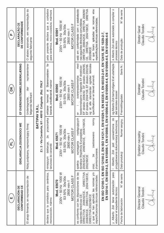
Use of prescribed PPE obligatory ( Protective Gloves )
Warning! Danger of accidental contact
Do not use discs for wood or metal
90254
Do not wash with water under pressure
Recovery tank water level
Warning!Secure the carriage
Presence energyelectric
2
A Machine model M IP Level
B Item N Year of manufacture
C Serial number O Max tool diameter
D Power supply voltage P Internal tool
diameter
E Power supply frequency Q Accessories
F Current absorption R Accessories
G Installed power rating S Manufacturer’s
name
H Tool rotation speed T Manufacturer’s
name and address
I Class of protection U Certification Marks
L Starter capacitor
4. Machine descriptionThe CLASS site cutter is a machine intended specifically for cutting ceramics, marble, granite, bricks, concrete items and similar materials, up to a thickness of 40 mm.The machine uses a wet diamond tipped tool cutting system and is intended for personnel specialized in the construction sector.The operator works in front of the narrow side of the machine, within reach of the operating controls, and positions the material to be cut on the moving worktop. He/she starts the machine and moves the cutting head to bring the tool into contact with the material.
5. SignsSymbols and signs:Danger/prohibition stickers are applied to the machine where necessary. Look at these prior to using the machine.
A
A
Use of prescribed PPE obligatory (Safety eyewear and earmuffs)
Read operating instructions before each use.
ABD
E
C

25
ITGBMachine dimensions:CLASS 670 660 x 1070 x h. 1200 mmCLASS 670S 660 x 1070 x h. 1200 mmCLASS 900 660 x 1300 x h. 1200 mmCLASS 900S 660 x 1300 x h. 1200 mm
7. Installation
TRANSPORT
The CLASS machine is easy to carry by using the specially provided side handles(See picture 3).
3
Before carrying the machine make sure that:• The motor slide is locked in place with the two
cutting adjustment knobs on the slide rail.• The motor carriage is completely lowered and
locked with the locking lever.• The inclination adjustment knobs are properly
tightened.• The tube-holder rod is out of its housing.
TO MOVE THE MACHINE
a) Use a 4 (four)-arm tie rod, making use of the hooks in the transport handles (See picture 4).
b) With the aid of a second person, move the machine by means of the transport handles.
(See picture 3)
6. Technical Data
Voltage: 230V 50/60Hz~Power absorbed: 1000 W
Admissible working conditions: INTERMITTENT S3 SERVICE 30s Under load running 30s ReposeRotation speed: 2800 min-1Condenser: 14 µFThermal circuit breaker: 170°CIP Degree: 54
CLASS 670 CLASS 900 CLASS 670S CLASS 900S
Operating weight 37 Kg 41 Kg
Tank capacity (min/max)
12/15,5Lt 15/19,5Lt
CUTTING TOOLDIAMOND BLADE WET CUTTINGCONTINUOUS CROWN:ceramic, single-fired ceramic, cotto and marble (max. thickness 20 mm.)
THE TOOL / MATERIAL TO BE CUT MATCHES ARE PURELY INDICATIVE.ALWAYS FOLLOW THE INTENDED USE INDICATIONS PROVIDED BY THE CUTTING TOOL MANUFACTURER BEFORE ANY APPLICATION.
CLASS 670 CLASS 900 CLASS 670S CLASS 900S
Max tool diameter: Ø200mmCentre hole: 25,4 mmMax. cutting depth:90° cut: 40 mm
Max. cutting length 670 mm 900 mm
Water recirculation pump: S0 230V 50/60Hz

26
ITGBc) lock the leg with the relative locking pin;d) tighten the wheel support setscrew
(see picture 5);e) repeat the operation for the other wheel.
CAUTION!
IN ORDER TO FACILITATE THE CLASS MACHINE MOVEMENT IN THE YARD, WE RECOMMEND LOWERING IT UNTIL THE LOWERED POSITION.
a) loosen the leg locking pins on the front side, one at a time, holding the machine from the transport handles;
b) lower the machine front side, making the legs slide inside the supports until the leg middle hole matches the hole of the supports (see picture 6);
c) lock the legs by means of the relevant leg locking pins;
d) repeat the operations indicated in points (a), (b), (c) for the rear side.
6
MOVE THE MACHINE AS INDICATED IN PICTURE 7
7
4
To move the machine, use a four-arm tie rod with the capacity to lift 200 kg or at least 20% more than the machine weight, by making use of the hooks in the transport handles (see picture 4).
HANDLING
By using the “transport wheels” accessory (standard for Art. 65671, 65901), the machine can be moved with the aid of a second person.
CAUTION!
IN ORDER NOT TO COMPROMISE THE MACHINE STABILITY, KEEP STRICTLY TO THE FOLLOWING PROCEDURES.HOLD THE MACHINE DURING THE OPERATIONS DESCRIBED BELOW.
When the machine is in working position:a) loosen the leg locking pin on the opposite side of
the control unit;b) lift the leg and put it in the wheel support (see picture 5);
5

27
ITGB CAUTION!
For correct machine positioning, make sure that the leg upper hole matches the leg coupling hole. (See picture 10)Hold the machine during the leg locking phases.
c) Lock the legs one at a time (See picture 10).
10
d) Repeat the operation for the opposite side.e) Loosen the motor head locking knobs.f) Insert the tube-holder rod in its seat. (See picture 11)
11
g) Insert the tile bearing extension(See picture 12).
POSITIONING
Place the machine on a stable surface.
CAUTION!
Make sure that:- The motor head is locked by means of the
relevant locking knobs located on the slide rail (See picture 8).
- The motor head inclination adjustment lever is properly tightened (See picture 8).
8
To place the machine in working position, proceed as follows:
a) Put the leg locking pins in release position. (See picture 9)b) By means of the transport handles, lift one side
of the machine until the working position. (See picture 9)
9

28
ITGB
14
CONNECTING TO POWER SUPPLY
CAUTION!
The machine is to be connected to the power supply by a residual current circuit breaker (RCCB) with the following characteristics:
RCCB In 6 A Id 30 mA
Transformer 230 V 50 Hz 1500 WCont. duty
N.B. To ensure correct functioning, periodically check the efficiency of RCCBs by pressing the push-button on the front of the device.
- Make sure that the section of the power supply cable cores has been measured according to the starting current and its length.
For cables up to 50 m long, a section of 2.5 mm2 is enough.
- Before connecting the machine to the power socket, check that the power supply voltage corresponds to that shown on the plate on the machine.
- The machine must be connected to an effective earth wire. In case of doubt, do not connect the machine.
BLADE ASSEMBLY / DISASSEMBLY
Before performing any operation or adjustment, disconnect the machine from the supply mains.Loosen both nuts located on the blade cover guard and remove it.Remove the blade fixing nut using the 19 mm spanner and a 5 mm Allen key.
12
CHECKING BEFORE USE
CAUTION!
THE CLASS MACHINE HAS BEEN DESIGNED FOR WORKING WITH WATER.
13
Before any cutting operation, make sure that the water level inside the basin is correct. (See picture 13)
ADJUSTMENT OF COOLING WATER
Through an on-off valve placed on the disk protection, the water flow can be adjusted according to the type of material to be cut.(See picture 14) The innovative Spray System cooling system makes it possible and allows the disk to be always wet.

29
ITGB CAUTION!
THE BLADE FIXING NUT HAS A LEFT-HAND THREAD.
15
After dismantling the blade, clean the blade flanges carefully and check them for wear.Grease any surface with fine oil and install the new blade. Check for correct direction of rotation as clearly indicated on the tool.
CONTROL DEVICES
CAUTION!
The CLASS machine is equipped with a control board made up of:
1) START BUTTON (GREEN COLOUR):
Press the button fully to activate machine starting.
2) MANUAL STOP BUTTON (RED COLOUR)
Press the button fully to activate machine stop.
16
3) DEVICE FOR DISCONNECTION FROM THE MAINS (PLUG):
Machine power supply point. During the maintenance phases, take out the
device plug in order to disconnect the machine from the mains.
A- 65670, 65900 VersionB- 65671, 65901 Version
17
4) LASER MARKER (OPTIONAL ON CLASS 670 AND CLASS 900)
It projects the cutting line on the table. It is enabled when the machine is connected to
the mains.
18

30
ITGBThanks to the great versatility of the CLASS machine, it is possible to carry out different types of cutting.Position the piece which needs cutting on the working table and make sure that it is properly leaned against the tile-stopper. If necessary, a bearing square can be of help (See picture 18).
18
CAUTION!
THE MILLIMETRE RULER PLACED ON THE WORKING TABLE HELPS ONLY WITH THE CARRYING OUT OF LINEAR CUTTING.In order to carry out any diagonal cutting, lean the tile against the square and go on with the cutting operation (See picture 19).
19
9. Cutting a surface at 45°
CAUTION!
Before positioning the motor head ensure that:- The machine is turned off.- The cutting tool is not in motion.
8. Cutting on the table
CAUTION!
BEFORE PERFORMING THE CUTTING OPERATIONS, MAKE SURE THAT THE MATERIAL IS PROPERLY LEANED AGAINST THE TILE STOPPER.
CAUTION!
BEFORE STARTING THE CUTTING OPERATIONS, THE OPERATOR MUST MAKE SURE THAT AT LEAST 150 cm ARE LEFT FREE AROUND THE MACHINE (Pos. 2 Picture 15).IN ORDER TO WORK IN SAFETY CONDITIONS, DO NOT LET OTHER PEOPLE REMAIN NEAR THE MACHINE DURING THE CUTTING OPERATIONS.THE OPERATOR STANDS IN THE WORKING POSITION (Pos. 1 Picture 15) DURING THE DIFFERENT MACHINE OPERATION PHASES.
1
2
1.5m
1.5m
1.5m
15

31
ITGBLASER MARKER
CAUTION!
CLASS IIIA 635 nm, < 5 mW LASER INSTRUMENTBy means of the laser marker accessory, the cutting operations can be accelerated.
CAUTION!
THE LASER MARKER STARTS WORKING ONCE THE MACHINE IS CONNECTED TO THE POWER SUPPLY.
22
CUTTING WITH LASER MARKER
- connect the machine to the power supply;- position the piece to be cut making sure that the
line indicated by the laser marker matches the reference on the material to be cut;
- perform the cutting operation as indicated in the paragraph: “cutting on the table”
(See picture 22).
CAUTION!
DO NOT MODIFY THE MARKER POSITION BY TURNING THE BEAM TOWARDS THE OPERATOR’S EYES.DO NOT GAZE AT THE BEAM WITH THE NAKED EYE OR LOOK DIRECTLY WITH OPTICAL INSTRUMENTS.
Referring to the graded scale located on the machine upright, move the motor head to the JOLLY position and tighten the knobs.(See picture 20) With the locking lever, lower the cutting head until placing the blade some millimetres below the table level.
20
CAUTION!
BEFORE ANY CUTTING MAKE SURE THAT THE TILE TO BE CUT IS PROPERLY LEANED AGAINST THE TILE-STOPPER.
With the CLASS machine it is also possible to set out:a- the cutting length with the cutting adjustment
knobs;b- the cutting depth with the locking lever;c- the straight cut measurement with the tile
bearing square as well as the ruler placed on the working table.
In order to carry out special working it is possible to set out any cutting inclination ranging from 0° to 45° as marked on the machine side (See picture 16).
21

32
ITGB10. Residual Risks
During the design phase, BATTIPAV SRL paid particular attention to the aspects that may generate risks for the safety and health of operators.In spite of this, there are still some potential risks, which are described below:
CAUTION!
• Danger of presence of electric current: The machine has an internal electric system. CONNECT THE MACHINE TO A SYSTEM
WITH DIFFERENTIAL PROTECTION AND EFFECTIVE EARTH WIRE.
CAUTION!
• Danger of prolonged exposure to noise: The continuative use of the machine causes an
exposure to noise levels above 85 dB (A). OPERATORS MUST USE PROPER EAR
DEFENDERS.
CAUTION!
• Danger of exposure to fragments of materials. OPERATORS MUST WEAR PROTECTIVE GOGGLES.
CAUTION!
• Danger of accidental contact with the moving tool.
OPERATORS MUST WEAR HEAVY PROTECTIVE GLOVES
ALWAYS STAY IN THE WORKING POSITION (Pos. 1 picture 15) DURING THE MACHINE OPERATION PHASES:- During material loading;- During material cutting;- During the cutting tool deceleration following the
machine stop.
ADJUSTMENT OF THE TRACER
In case the marker is not aligned with the cutting line, its correct alignment can be adjusted.In order to correctly position the marker, proceed as follows:- Loosen the three bulb locking screws so that it
can be moved (See picture 23).
23
- Position a reference properly on the tool cutting line (See picture 22).
- Insert the 5 mm Allen wrench provided in the hexagonal slot located on the bulb.
(See picture 23)
- Using the Allen wrench, turn the bulb until aligning the mark with the tool cutting line.
(See picture 22)
CAUTION!
DURING THE ADJUSTMENT OPERATIONS, MAKE SURE THAT THE LINE PRODUCED BY THE MARKER DOES NOT REACH THE OPERATOR’S EYES.
CAUTION!
THE MANUFACTURER DECLINES ANY LIABILITY FOR THE USE OF THE LASER MARKER IN APPLICATIONS OTHER THAN THE INDICATED APPLICATION.

33
ITGB
25
For a greater efficiency of the patented SPRAY SYSTEM lubrication system, clean it regularly as indicated. (See pictures 26 and 27)
26
27
11. Maintenance
CAUTION!
BEFORE PERFORMING ANY OPERATION OR ADJUSTMENT, DISCONNECT THE MACHINE FROM THE SUPPLY MAINS.
CLEANING
CAUTION!
DO NOT WASH THE MACHINE WITH HIGH PRESSURE WATER JETS
It is extremely easy to clean the CLASS machine by loosening the locking nuts and dismantling the working table.Through the tap located on the bottom of the recovery tank, remove any working residual from the machine (See picture 24).
24
CAUTION!
AFTER THE TANK CLEANING OPERATIONS, PLACE THE WORKING TABLE BACK IN POSITION, OBSERVING THE DISTANCE FROM THE LEG SUPPORT (SEE PICTURE 25).

34
ITGB12. Disposal
In the event of scrapping the entire machine, it must be disposed of in accordance with the methods laid down by current legislation.
Electric MotorAluminium ALSteel ACCopper CUPolyamide PA
Main CasingSteel ACPolyamide PAAluminium AL
Submerged PumpPolyamide PASteel ACAluminium ALCopper CUEpoxy Resin
W.E.E.E. IT08020000002803 The European Directive 2002/96/CE arranges that in the event of scrapping of electrical equipment, they must not be disposed of city solid refusals but collected separately, in order to optimize the level of recovery and recycling of the materials and above all in order to prevent damages to health and environment.To comply with European Directive 2002/96/CE, all electrical equipments must be marked with crossed basket symbol.The packing of the machine will be disposed of in accordance with the methods laid down by current legislation.For further information concerning disposal of electrical equipment, please refer to public administration service.
MOTOR CARRIAGE ADJUSTMENTThe motor carriage is provided with two registers for the motor head vertical play adjustment.For correct adjustment, proceed as follows:- with a 3 mm Allen wrench, screw both front
adjustment dowels (A), until the play is eliminated; (See picture 28)
28
- repeat the operation for both back adjustment dowels (B) (See picture 29).
29
CAUTION!
TIGHTEN THE FOUR REGISTERS EQUALLY IN ORDER TO OBTAIN SUITABLE SMOOTHNESS.

35
ITGB13. Troubleshooting
Faul
The machine does not work.
If lubrication does not arrive atthe disk with the pump running.
Motor gives off unpleasant odour.
Machine is difficult to start.
The machine is cutting out ofsquare.
The laser marker does not work.
Cause
The power supply cable isdamaged or not properlyconnected.
No voltage in the socket.
Control switch is damaged.
The sprayer unit is clogged.
Water may have seeped throughinside the motor
Capacitor is damaged.
Motor bearings are damaged.
The tile supports are not at rightangles with the cutting disc.
The disc is not suitable for thetype of material to be cut.
The laser unit is damaged.
The marker feeder is damaged.
Remedy
Press the plug firmly into thepower socket. Check the powersupply cable.
Have the socket checked.
Consult local dealer forreplacement.
Dismantle the sprayer assembledinside the disk cover and removeany possible residuals.
Unplug the power supply cableand consult local dealer.
Unplug the power supply cableand consult local dealer.
Unplug the power supply cableand consult local dealer.
Using a square, adjust the tilesupports to 90° in relation to thecutting line of the disc.
Replace the disc with a moresuitable one.
Contact your local dealer for areplacement.
Contact your local dealer for areplacement.
HAVE YOUR TOOL REPAIRED BY A QUALIFIED PERSON
This electric tool complies with the relevant safety rules. Repairs should only be carried out byqualified persons using original spare parts, otherwise this may result in considerable danger to theuser.

Art. 65022A
La riproduzione anche parziale e la divulgazione di questo documento, con qualsiasi mezzo, non sono consentite.Eventuali infrazioni saranno perseguite nei modi e nei tempi previsti dalla legge. Edizione 2013. Con riserva di modifiche.


![IOP P UBLISHING P LASMA S CIENCE AND T ECHNOLOGY Plasma ...plasma.szfki.kfki.hu/~zoli/pdfs/PSST_2011_Schulze_Secondary_elect… · various applications of plasma processing [1,2]](https://img.pdfslide.us/doc/110x75/5eae00c4e9a531317649d41d/iop-p-ublishing-p-lasma-s-cience-and-t-echnology-plasma-zolipdfspsst2011schulzesecondaryelect.jpg)


![0022-3727 47 47 475202plasma.szfki.kfki.hu/~zoli/pdfs/JPD_2014_Korolov_Breakdown_in_air.pdf · For gas breakdown in direct-current (DC) !elds, in his pioneering work [8], Paschen](https://img.pdfslide.us/doc/110x75/5e0be2736bee664c93328fff/0022-3727-47-47-zolipdfsjpd2014korolovbreakdowninairpdf-for-gas-breakdown.jpg)