Embed Size (px)
Citation preview

INSTRUCTIVE
MG-7000CURTAIN
WALL
MG-7000CURTAIN WALL
8120 NW 84 ST. MIAMI, FL 33166 PHONE:(305) 470-8284 FAX:(305) 470-8285 EMAIL:[email protected]

INSTALLATION INSTRUCTIONS
Page -DATE
I
PRELIMINARY
OCTOBER 9 -2013
Wear the necessary personal protective equipment for product installation.
Take safety precautions when performing the activity.
Work tools must be used properly.
Check tools conditions before using them.
Keep order and cleanliness.
HSE REGULATIONS
MG-7000CURTAIN
WALL
8120 NW 84 ST. MIAMI, FL 33166 PHONE:(305) 470-8284 FAX:(305) 470-8285 EMAIL:[email protected]

INSTALLATION INSTRUCTIONS
Page -DATE
1
CONTENT
OCTOBER 9 -2013
INSTALLATION INSTRUCTIONSINTRODUCTION.............................................................................................................. 2
PARTS DESCRIPTIONSEXTRUSIONS................................................................................................................. 3-6MISCELLANEOUS .......................................................................................................... 7-10
INSTALLATIONSTEP 1:INSPECTION............................................................................................................... 11VERIFICATION............................................................................................................. 12
STEP 2:VERIFICATION OF THE FRAME ANCHORING METHODS....................................................... 13PERIMETER ANCHOR.................................................................................................... 14-15VERTICAL MULLION....................................................................................................... 16VERTICAL MULLION OUTSIDE CORNER............................................................................. 17STEEL REINFORCING..................................................................................................... 18SHEAR BLOCK ASSEMBLY............................................................................................. 19HORIZONTAL MEMBERS................................................................................................ 20HORIZONTAL MEMBERS OUTSIDE CORNER....................................................................... 21PRESSURE PLATE......................................................................................................... 22-23PRESSURE PLATE LAYOUT............................................................................................. 24FACE COVER............................................................................................................... 25-26
STEP 3:INSTALL TYPICAL VERTICAL SPLICE.................................................................................. 27-28
STEP 4:ANCHOR INSTALLATION................................................................................................. 29-30STEEL ANCHOR INSTALLATION........................................................................................ 31
STEP 5:REINFORCEMENT.......................................................................................................... 32-33
STEP 6:HORIZONTAL MEMBERS INSTALLATION............................................................................ 34HORIZONTAL MEMBERS OUTSIDE CORNER INSTALLATION.................................................. 35
STEP 7:INSTALL 90° ADAPTER................................................................................................... 36
STEP 8:INSTALL 90° INTERIOR COVER........................................................................................ 37
STEP 9:INSTALL SPANDREL GLASS ADAPTOR.............................................................................. 38
STEP 10:INSTALL GLAZING ADAPTOR........................................................................................... 39
STEP 11:INSTALL JOIN PLUGS.................................................................................................... 40
STEP 12:INSTALL BLOCK AND SIDE BLOCK INSTALLATION............................................................... 41-42
STEP 13:INSTALL GLASS............................................................................................................ 43-44
STEP 14:INSTALL EXTERIOR COVERS........................................................................................... 45-47
GLAZING DETAILGLAZING DETAIL............................................................................................................. 48-50
MG-7000CURTAIN
WALL
8120 NW 84 ST. MIAMI, FL 33166 PHONE:(305) 470-8284 FAX:(305) 470-8285 EMAIL:[email protected]
INSTALLATION INSTRUCTIONS
Page -DATE
2
INTRODUCTION
OCTOBER 9 -2013
The is a Curtain Wall system.
This instructive illustrates the correct way toinstall the system.
Check that all parts, glass and materials are inright conditions, verify that the quantities anddescriptions match production planes.
Due to the variations that present in the productwe recommend to solve any concerns.
INTRODUCTION
MG-7000CURTAIN
WALL
8120 NW 84 ST. MIAMI, FL 33166 PHONE:(305) 470-8284 FAX:(305) 470-8285 EMAIL:[email protected]
MG7000
MR. GLASS consulting in order

PART DESCRIPTION
ES-7525-001 HEAD / SILL STD.
ES-7525-002 HEAD / HORIZONTAL (OPEN)
ES-7525-003JAMB / STD. MULLION/
HORIZONTAL
ES-7525-004 VERTICAL MULLION (HEAVY)
ES-7525-005SNAP INTERIOR COVER (HEAD
/ SILL / HORIZONTAL)
ES-7525-006 SHEAR BLOCK
ES-7525-007 ALT. VERTICAL MULLIONBUTT GLAZED
ES-7525-008 MULLION SPLICE
INSTALLATION INSTRUCTIONS
Page -DATE
3
EXTRUSIONS
OCTOBER 9 -2013
MG-7000CURTAIN
WALL
8120 NW 84 ST. MIAMI, FL 33166 PHONE:(305) 470-8284 FAX:(305) 470-8285 EMAIL:[email protected]

ES-6025-007STD. PRESSURE PLATE
1" GLASS
ES-6025-008DEEP PRESSURE PLATE
1 5/16" GLASS
ES-6025-009 STANDARD COVER
ES-6025-010 JAMB ANCHOR
ES-6025-011 MULLION ANCHOR
ES-6025-012 SPANDREL GLASS ADAPTER
ES-6025-013 POCKET FILLER
ES-6025-014 PANEL INFILL ADAPTER
INSTALLATION INSTRUCTIONS
Page -DATE
4
EXTRUSIONS
OCTOBER 9 -2013
MG-7000CURTAIN
WALL
8120 NW 84 ST. MIAMI, FL 33166 PHONE:(305) 470-8284 FAX:(305) 470-8285 EMAIL:[email protected]

ES-6025-015 90° ADAPTER
ES-6025-016 90° CORNER PRESSURE PLATE
ES-6025-017 90° INTERIOR ADAPTER
ES-6025-018 90° INTERIOR COVER
ES-6025-019 PERIMETER PRESSURE PLATE
ES-6025-021 GLAZING ADAPTOR
ES-6025-023 PERIMETER ANCHOR
ES-6025-024SHALLOW PRESSURE PLATE
9/16" GLASS
INSTALLATION INSTRUCTIONS
Page -DATE
5
EXTRUSIONS
OCTOBER 9 -2013
MG-7000CURTAIN
WALL
8120 NW 84 ST. MIAMI, FL 33166 PHONE:(305) 470-8284 FAX:(305) 470-8285 EMAIL:[email protected]

ES-6025-025PRESSURE PLATE PERIMETER
(9/16" GLASS)HEAD / SILL / JAMB
SHEAR BLOCK FOR 90°OUTSIDE CORNER (LH)
SHEAR BLOCK FOR 90°OUTSIDE CORNER (RH)
ALU-A-0281 1/2" x 1 1/2" x 1/8" COVERFOR 90° OUTSIDE CORNER
(9/16" GLASS)
ALU-A-0271 3/4" x 1 3/4" x 1/8" COVERFOR
90° OUTSIDE CORNER(1 5/16" GLASS)
ALU-A-028
ALU-A-028
ES-7525-50 MULLION ANCHOR
ES-7525-51 JAMB ANCHOR
INSTALLATION INSTRUCTIONS
Page -DATE
6
EXTRUSIONS
OCTOBER 9 -2013
MG-7000CURTAIN
WALL
8120 NW 84 ST. MIAMI, FL 33166 PHONE:(305) 470-8284 FAX:(305) 470-8285 EMAIL:[email protected]

PART DESCRIPTION
ES-6025-G01
ES-6025-G02
ES-6025-G03
ES-6025-G04
ES-6025-G05
ES-6025-B02
SPACER AT JAMB
SPACER @ JAMB FOR 1 5/16"GLASS
INTERIOR SPACER FORSILICONE BUTT GLAZE
SETTING BLOCK FOR 1" GL.(1/8" x 7/16")
ES-6025-G06
ES-6025-G07
ES-6025-G08
EXTERIOR GASKET FOR 9/16"GLASS
1/4" x 1/4"POLYURETHANE TAPE(ADHESIVE 1 SIDE)
3/16" X 1/4" DENSEFOAM TAPE
(ADHESIVE 1 SIDE)
ES-6025-B03
ES-6025-B01
SIDE BLOCK
SETTING BLOCK FOR 1/4"SPANDLEL GLASS
(1/2" x 7/16")
INTERIOR / EXTERIORGASKET
ISOLATOR
CODE
M1
M2
M3
M4
M5
M6
M7
M8
M9
M10
M11
INSTALLATION INSTRUCTIONS
Page -DATE
7
MISCELLANEOUS
OCTOBER 9 -2013
MG-7000CURTAIN
WALL
8120 NW 84 ST. MIAMI, FL 33166 PHONE:(305) 470-8284 FAX:(305) 470-8285 EMAIL:[email protected]

ES-6025-B08
ES-6025-B09
ES-6025-C01
ES-6025-C02
ES-6025-C03
ES-6025-B04
ES-6025-B05
ES-6025-B06
ES-6025-B07
SETTING BLOCK FOR 1 5/16"GLASS
(1 3/8" x 3/16")
SETTING BLOCK FOR 9/16"IMPACT GLASS(5/8" x 3/16")
JOINT PLUG FOR 1" GL.
JOINT PLUG EXTENSION(1/2" x 7/16")
JOINT PLUG FOR BUTTGLAZING
END PLUG FOR HEAD /SILL
MULLION END CAPSTANDARD
(2 1/2" x 2 7/16")
MULLION END CAP(2 1/2" x 2 3/4")
MULLION END CAP(2 1/2" x 2 1/8")
ES-6025-B10
ES-6025-B11
JOINT PLUG FOR 1 5/16" GL.
JOINT PLUG FOR 9/16" GL.
M12
M13
M14
M15
M16
M17
M18
M19
M20
M21
M22
INSTALLATION INSTRUCTIONS
Page -DATE
8
MISCELLANEOUS
OCTOBER 9 -2013
MG-7000CURTAIN
WALL
8120 NW 84 ST. MIAMI, FL 33166 PHONE:(305) 470-8284 FAX:(305) 470-8285 EMAIL:[email protected]

ES-6025-C04 90° CORNER MULLION ENDCAP STANDARD
90° CORNER MULLION END CAP
STD. FLOOR ANCHOR -WINDLOAD 4" x 4" x 1/4" ANGLE, 5"
LG.
STD. FLOOR ANCHOR -DEADLOAD 4" x 4" x 1/4" ANGLE, 5"
LG.
ANCHOR METAL SEPARATOR3" x 5" x 1/16"
ES-6025-M01
ES-6025-M02
ES-6025-M03
ES-6025-C05
ES-6025-C06 90° CORNER MULLION ENDCAP 9/16" GLASS
SCREW
SCREW
SCREW
SCREW
#8 x 1/2" PHSMS
#12 x 3/4" PHSMS
#12 x 3/4" FHSMS
1/4" - 20 x 1 1/2" HH CURTAINWALL "F" POINT.
FLOOR ANCHOR OUTSIDECORNER
ES-6025-M16
M23
M24
M25
M26
M27
M28
M29
M30
M31
M32
M33
INSTALLATION INSTRUCTIONS
Page -DATE
9
MISCELLANEOUS
OCTOBER 9 -2013
MG-7000CURTAIN
WALL
8120 NW 84 ST. MIAMI, FL 33166 PHONE:(305) 470-8284 FAX:(305) 470-8285 EMAIL:[email protected]

SCREW #10 x 3/8" HWH CURTAINWALL AB
SCREW
SCREW
1/4" x 1 " HWH CURTAIN WALL ABPT. SELF TAPPING SCREW
HBOLT 1/2" - 20 x 4" HWHMS(SEE ENGINEERINGCALCULATION FOR
COREECT BOLT SIZE)
SCREW
1/2" PLAIN FLAT WASHERFLAT WASHER
1/2" LOCK WASHERLOCK WASHER
1/2" - 20 HEX BOLT NUT HHMS
1/4" - 20 x 1/2" HH CURTAINWALL "F" POINT.
BOLT NUT
SCREW #8 x 1/2" FHSMS
ES-6025-P01 COVER SPLICE SLEEVE
REINFORCEMENT STEEL REINFORCEMENT
BUPON SPACER COVER SPLICE SLEEVE
M34
M35
M36
M37
M38
M39
M40
M41
M42
M43
M44
.INTERIOR GLAZING
GASKETM45
INSTALLATION INSTRUCTIONS
Page -DATE
10
MISCELLANEOUS
OCTOBER 9 -2013
MG-7000CURTAIN
WALL
8120 NW 84 ST. MIAMI, FL 33166 PHONE:(305) 470-8284 FAX:(305) 470-8285 EMAIL:[email protected]

INSTALLATION INSTRUCTIONS
Page -DATE
11OCTOBER 9 -2013
STEP 1
1.1. Measure rough opening in several places todetermine variations.
1.2. Check all the material upon arrival for quantityand damage.
1.3. Remove all materials that interfere with theproper installation of the unit. If you have anyirregularities notify the general contractor.
OPENING
D.L
.O
OPE
NIN
G
D.L.O
D.L
.O
D.L.O D.L.O
MG-7000CURTAIN
WALL
8120 NW 84 ST. MIAMI, FL 33166 PHONE:(305) 470-8284 FAX:(305) 470-8285 EMAIL:[email protected]

INSTALLATION INSTRUCTIONS
Page -DATE
12OCTOBER 9 -2013
1.4. The rough opening should be checked for thecorrect size as determined by dimensions listedin the architectural specifications an the shopdrawings.
1.5. Measure rough opening to determine frame widthand frame height dimensions. Allow 1/2" minimumclearance for shimming and caulking aroundperimeter of frame.
1.6. Verify the dimensions:
VERTICALS FRAME HEIGHTVERTICAL FACE COVER FRAME HEIGHTINTERMEDIATE HORIZONTALS D.L.O.HEAD AND SILL D.L.O.HORIZONTAL PRESSURE PLATE D.L.O. - 1/8"HORIZONTAL FACE COVER D.L.O. - 1/16"SNAP INTERIOR COVER D.L.O. - 1/32"
1/2" MIN.
1/2
" MIN
.
2 1/2"
ROUGH OPPENING
FRAME WIDTH
RO
UG
H O
PPEN
ING
FRAM
E HEI
GHT
MG-7000CURTAIN
WALL
8120 NW 84 ST. MIAMI, FL 33166 PHONE:(305) 470-8284 FAX:(305) 470-8285 EMAIL:[email protected]

INSTALLATION INSTRUCTIONS
Page -DATE
13OCTOBER 9 -2013
1.7. The following details represent common typesof frame installation.
MULTI-SPAN
TWIN SPAN
SINGLE SPAN
Refer to shop drawings for exactlayout of frames; The configurationvaries depending on the type ofvertical end attachment requiredfor a given project. A qualifiedengineer must approve all anchorsand mullions for wind load anddead load.
ANCHORS DETAIL
STEP 2
MG-7000CURTAIN
WALL
8120 NW 84 ST. MIAMI, FL 33166 PHONE:(305) 470-8284 FAX:(305) 470-8285 EMAIL:[email protected]

1.8. When using continuous perimeter anchor, thetop and bottom of jamb and vertical mullionsmust be notched as shown in the detail. Forjamb mullion and vertical mullion with perimeteranchors ONLY.
1.9. Verify the dimensions in the framing:
Horizontal perimeter anchor: L=F.W. + 7/16"
Vertical perimeter anchor: L=F-H. + 1 11/16"
INSTALLATION INSTRUCTIONS
Page -DATE
14OCTOBER 9 -2013
Do not notch verticals when usingmullion end anchorsES-6025-010 andES-6025-011.
7/8
"7
/8"
Detail 1.8
MG-7000CURTAIN
WALL
8120 NW 84 ST. MIAMI, FL 33166 PHONE:(305) 470-8284 FAX:(305) 470-8285 EMAIL:[email protected]

INSTALLATION INSTRUCTIONS
Page -DATE
15OCTOBER 9 -2013
2.1. Install perimeter anchor with appropriateperimeter fasteners. Refer to shop drawings orengineering calculations for type and spacing offasteners.
2.2. Shim hi-impact plastic; as required to installanchors level.
2.3. Run continuous sealant along the perimeterbetween the anchors and the substrate.
2.4. Verify the 0.313" diameter weep holes inperimeter anchor (exterior face only) at sill 3"from center line of vertical on each side.
Detail 2.4Detail 2.2
MG-7000CURTAIN
WALL
8120 NW 84 ST. MIAMI, FL 33166 PHONE:(305) 470-8284 FAX:(305) 470-8285 EMAIL:[email protected]

4.1. Verify the dimensions in the vertical mullion.
INSTALLATION INSTRUCTIONS
Page -DATE
16OCTOBER 9 -2013
Do not notch verticals when usingmullion end anchorsES-6025-010 andES-6025-011.
Detail 1.10
3.5"
1.25"2.5"
D.L.O.
2.5"
2.5"
D.L.O.
1.25"
1.25"
L=FH
0.875"
MG-7000CURTAIN
WALL
8120 NW 84 ST. MIAMI, FL 33166 PHONE:(305) 470-8284 FAX:(305) 470-8285 EMAIL:[email protected]

1.11. Verify the dimensions in the vertical mullionoutside corner.
1.12. If engineering calculations require the verticalmullions to be reinforced with steel, securethe reinforcing to the vertical usingappropriate fasteners.
1.13. Shows in the detail the typical method forreinforcing in the vertical mullion. Refer toapproved shop drawings for placement, sizeand quantity of reinforcing required.
INSTALLATION INSTRUCTIONS
Page -DATE
17OCTOBER 9 -2013
3.0" 0.875"
1.25"2.5"
D.L.O.
2.5"
D.L.O.
1.25"L=FH
1.25"2.5"
Detail 1.11
MG-7000CURTAIN
WALL
8120 NW 84 ST. MIAMI, FL 33166 PHONE:(305) 470-8284 FAX:(305) 470-8285 EMAIL:[email protected]

1.14. Verify the dimensions, Star at 3" from bothends of the mullion and install a fastener onboth sides of the mullion tongue.
1.15. Stagger the fasteners on either side of themullion going up the vertical.
1.16. Verify that the screws are sealant on thehead.
INSTALLATION INSTRUCTIONS
Page -DATE
18OCTOBER 9 -2013
Detail 1.14
3"
MAX 19"
MAX 19"
MAX 19"
3"
When engineering calculations requirethe vertical mullions to be reinforcedwith steel.
Detail 1.14
Exact size of reinforcing, size andlocation of fasteners to be determinedby qualified enginner.
MG-7000CURTAIN
WALL
8120 NW 84 ST. MIAMI, FL 33166 PHONE:(305) 470-8284 FAX:(305) 470-8285 EMAIL:[email protected]

INSTALLATION INSTRUCTIONS
Page -DATE
19OCTOBER 9 -2013
Standard Shear Blocks are used to attach horizontalmembers to the jamb and vertical mullion.
3.1. Attach Shear Block to vertical with two fastenersas the detail. This is for typical Shear Blocksconfiguration.
3.2. Attach angles to outside corner vertical with twofasteners per angle. This is for Outside Cornerconfiguration.
Detail 3.2Detail 3.1
MG-7000CURTAIN
WALL
8120 NW 84 ST. MIAMI, FL 33166 PHONE:(305) 470-8284 FAX:(305) 470-8285 EMAIL:[email protected]

1.17. Verify the cut of the all horizontal membersto de D.L.O. as de shop drawings.
1.18. Verify the holes along the V-Grooves forreceive Shear Blocks as detail.
1.19. Open back head and sill members requiredholes to access anchor bolt.
INSTALLATION INSTRUCTIONS
Page -DATE
20OCTOBER 9 -2013
Detail 1.19
The holes for access anchor bolt, asrequired by approved shop drawings orengineering calculations.
L= D.L.O. WIDTH
0.563" 0.563"
0.625"
0.625"
L= D.L.O. WIDTH
2"
1.45"
2.25"
2"
2.5"
2.5" D.L.O. WIDTH 2.5"
Detail 1.18
MG-7000CURTAIN
WALL
8120 NW 84 ST. MIAMI, FL 33166 PHONE:(305) 470-8284 FAX:(305) 470-8285 EMAIL:[email protected]

1.1. Verify that all the horizontals members arecutting to 45° as the detail.
1.2. For head and sill, verify two holes forattachment of the angles.
1.3. For horizontal open (ES-7525-002) verify twoholes countersink for attachment. See theposition in the detail.
1.4. Open back head and sill members require holesto access anchor bolt, as required byapproved shop drawings or engineeringcalculations.
INSTALLATION INSTRUCTIONS
Page -DATE
21OCTOBER 9 -2013
Detail 1.5
2.5"
2"
L=D.L.O. WIDTH +1.24"
L=D.L.O. WIDTH
45°
1.919"1.919"
4.394"
1.24"2.262"
4.737"Detail 1.3
Detail 1.4
0.62"
0.563"L=D.L.O.
0.62"
0.563"L=D.L.O.
0.62"
MG-7000CURTAIN
WALL
8120 NW 84 ST. MIAMI, FL 33166 PHONE:(305) 470-8284 FAX:(305) 470-8285 EMAIL:[email protected]

1.1. For SSG vertical mullion, the pressure plateare cutting as the detail.
1.2. All pressure plates have factory-punchedholes.
INSTALLATION INSTRUCTIONS
Page -DATE
22OCTOBER 9 -2013
Detail 1.1
1/16"
D.L.O. -1/8"
1/8"
D.L.O. -1 1/8" D.L.O. -2 3/8"
MG-7000CURTAIN
WALL
8120 NW 84 ST. MIAMI, FL 33166 PHONE:(305) 470-8284 FAX:(305) 470-8285 EMAIL:[email protected]

1.1. The length of the pressure plates must be thesame as the vertical mullions unless theverticals are spliced.
1.2. For vertical mullion spliced, cut pressure plateto accommodate fro 1/2" expansion joint asthe detail.
INSTALLATION INSTRUCTIONS
Page -DATE
23OCTOBER 9 -2013
Detail 1.1
For glass with different thickness,use the pressure plate indicated inthe description of parts.
MG-7000CURTAIN
WALL
8120 NW 84 ST. MIAMI, FL 33166 PHONE:(305) 470-8284 FAX:(305) 470-8285 EMAIL:[email protected]

1.1. Drill the additional holes if required to ensurethat end holes are within 1 1/2" of each end.
1.2. Center horizontal pressure plate in D.L.O.leaving 1/16" gaps at each end.
INSTALLATION INSTRUCTIONS
Page -DATE
24OCTOBER 9 -2013
Detail 1.1
Weep holes mus be in the topside of all horizontal pressureplate.
1 1/2"MAX @ 9" MAX @ 9"
D.L.O. /3 D.L.O. /3
3"
MAX.
1 1
/2"
MAX.
@ 9
"M
AX.
@ 9
"M
AX.
@ 9
"M
AX.
@ 9
"
MAX.
1 1
/2"
1 1/2"
MG-7000CURTAIN
WALL
8120 NW 84 ST. MIAMI, FL 33166 PHONE:(305) 470-8284 FAX:(305) 470-8285 EMAIL:[email protected]

1.1. For horizontal members, verify horizontal facecovers to the D.L.O. between verticals min.1/16".
1.2. Verify the weep holes at 1/3 points of coversas detail.
INSTALLATION INSTRUCTIONS
Page -DATE
25OCTOBER 9 -2013
Detail 1.2
For SSG vertical mullion, use thedetail to the pressure plate.
D.L.O.2.5" 2.5"
D.L.O. /3 D.L.O. /3
L= F.W. -1/16"
D.L.O. /3 D.L.O. /3 D.L.O. /3 D.L.O. /3 D.L.O. /3 D.L.O. /3
D.L.O. D.L.O. D.L.O.
D.L.O. + D.L.O. + 2.44" D.L.O. + 1.0"
MG-7000CURTAIN
WALL
8120 NW 84 ST. MIAMI, FL 33166 PHONE:(305) 470-8284 FAX:(305) 470-8285 EMAIL:[email protected]

1.1. The length of the vertical face cover must bethe same as the vertical mullions, unless theverticals are spliced.
1.2. If vertical mullions are spliced, the verticalcovers must be accommodate for the 1/2"expansion joint.
INSTALLATION INSTRUCTIONS
Page -DATE
26OCTOBER 9 -2013
Detail 1.2
1.82" 1.68"
1.2
5"
3.2
5"
MAX.
@ 9
"
2.7
5"
0.5
".75
".5
"2
.75
".5
"1
.25
"
MG-7000CURTAIN
WALL
8120 NW 84 ST. MIAMI, FL 33166 PHONE:(305) 470-8284 FAX:(305) 470-8285 EMAIL:[email protected]

STEP 3
INSTALLATION INSTRUCTIONS
Page -DATE
27OCTOBER 9 -2013
3.1. Insert a join plug extension (ES-6025-B07) inthe mullion.
3.2. Install the mullion splice (ES-7525-006) andattach in the side as the detail.
3.3. Carefully slide the upper mullion down onto thesplice sleeve and place a 1/2" temporary shim betweenthe mullions to properly locate them.
3.4. Clean all the surface as recommended by sealantmanufacturer.
3.5. Apply silicone in the vertical cut.
Mullion splice joints for thissystems are not designed tocompensate for varying floorlevels.Face covers, pressure plate andmullion are staggered at splicelocations.Is recommends that vertical spliceline should be below theintermediate horizontal member.
MG-7000CURTAIN
WALL
8120 NW 84 ST. MIAMI, FL 33166 PHONE:(305) 470-8284 FAX:(305) 470-8285 EMAIL:[email protected]

INSTALLATION INSTRUCTIONS
Page -DATE
28OCTOBER 9 -2013
3.6. Secure the upper mullion to the mid anchors andremove the temporary shims.
3.7. Locate pressure plate fasteners 1 1/2" fromeach end off pressure plate slice as detail.
3.8. Apply silicone to the face and sides of the coversplice sleeve to create a water tight join and attach itthe lower face cover with a tow fasteners.
3.9. Prior to snapping on the upper portion of theface cover, apply sealant to the face of the splice.
The following details depicts a splicejoint of 1/2". The required joint widthmust be determined at the designstage and show on the approvedshop drawings, on a job by job basis.The actual width of this joint dependson the expected amount of thermalmovement plus the expect movementof the building structure.
MIN. 1"
MG-7000CURTAIN
WALL
8120 NW 84 ST. MIAMI, FL 33166 PHONE:(305) 470-8284 FAX:(305) 470-8285 EMAIL:[email protected]

STEP 4
INSTALLATION INSTRUCTIONS
Page -DATE
29OCTOBER 9 -2013
4.1. Install mullion end cap in the top and bottom ofthe vertical mullion. See parts description forinstall adequate.
4.2. Seal all screw heads with sealant.
4.3. Insert mullion anchors into the top end bottom ofthe mullion before erecting them into theopening.
Field drill anchorholes: Refer toapproved shopdrawings foranchor hole sizeand location.
MG-7000CURTAIN
WALL
8120 NW 84 ST. MIAMI, FL 33166 PHONE:(305) 470-8284 FAX:(305) 470-8285 EMAIL:[email protected]

INSTALLATION INSTRUCTIONS
Page -DATE
30OCTOBER 9 -2013
4.4. Install snap interior cover (ES-6025-005) asdetail.
Provide anchor fasteners perapproved shop drawings orengineering calculations.
MG-7000CURTAIN
WALL
8120 NW 84 ST. MIAMI, FL 33166 PHONE:(305) 470-8284 FAX:(305) 470-8285 EMAIL:[email protected]

INSTALLATION INSTRUCTIONS
Page -DATE
31OCTOBER 9 -2013
4.5. Install steel wind load and dead load anchors.
4.6. Anchors are normally template or line set beforemullions are hung.
4.7. Outstanding leg of anchor must be set at 90° tooffset line. The back of the vertical mullion should setabout 1" from the anchoring substrate.
MG-7000CURTAIN
WALL
8120 NW 84 ST. MIAMI, FL 33166 PHONE:(305) 470-8284 FAX:(305) 470-8285 EMAIL:[email protected]

STEP 5
INSTALLATION INSTRUCTIONS
Page -DATE
32OCTOBER 9 -2013
5.1. Slide reinforcement insert into mullion centeringon anchor location.
5.2. Put screw into first hole drilled to temporallyhold reinforcement insert in place for remainderof fabrication.
5.3. Install the vertical mullions in position and attachto the building structure per the "approved" shopdrawings.
Checking stress levels at point loadareas will require different anchors orpossibly steel reinforcing. A qualifiedengineer, should do these calculation.The hex nut bolt must be tightenedsufficiently to completely compressthe spring lock washer.
0.625" 0.619"
MG-7000CURTAIN
WALL
8120 NW 84 ST. MIAMI, FL 33166 PHONE:(305) 470-8284 FAX:(305) 470-8285 EMAIL:[email protected]

INSTALLATION INSTRUCTIONS
Page -DATE
33OCTOBER 9 -2013
5.4. Outstanding leg of clip must be set 90° tooffset line. The back of the vertical mullion shouldset 1" from the anchoring substrate.
5.5. Anchor metal separator (ES-6025-M03), mustbe installed between mullion and anchor.
5.6. For outside corner, use the floor anchorES-6025-M16.
3"
19
.5"
17
.61
" 14
.5"
3.1
08
"
1.0"
BO
T. T
O A
NC
HO
R1
.25
"
2.5
"
L=4
0"
MG-7000CURTAIN
WALL
8120 NW 84 ST. MIAMI, FL 33166 PHONE:(305) 470-8284 FAX:(305) 470-8285 EMAIL:[email protected]
STEP 6
INSTALLATION INSTRUCTIONS
Page -DATE
34OCTOBER 9 -2013
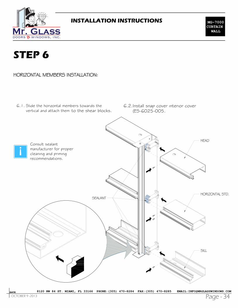
6.1. Slide the horizontal members towards thevertical and attach them to the shear blocks.
6.2.Install snap cover interior cover(ES-6025-005.
Consult sealantmanufacturer for propercleaning and primingrecommendations.
MG-7000CURTAIN
WALL
8120 NW 84 ST. MIAMI, FL 33166 PHONE:(305) 470-8284 FAX:(305) 470-8285 EMAIL:[email protected]
INSTALLATION INSTRUCTIONS
Page -DATE
35OCTOBER 9 -2013
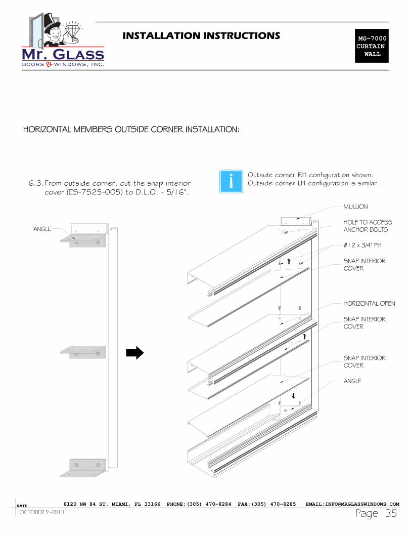
6.3.From outside corner, cut the snap interiorcover (ES-7525-005) to D.L.O. - 5/16".
Outside corner RH configuration shown.Outside corner LH configuration is similar.
MG-7000CURTAIN
WALL
8120 NW 84 ST. MIAMI, FL 33166 PHONE:(305) 470-8284 FAX:(305) 470-8285 EMAIL:[email protected]

L = F.H.1.500 MAX @ 9" 1.500MAX @ 9"MAX @ 9"
ES-6025-015
.312
MAX @ 9"
L = F.H.
ES-6025-017
1.500 MAX @ 18" 1.500MAX @ 18"MAX @18"
1.224
MAX @ 18"
STEP 7
INSTALLATION INSTRUCTIONS
Page -DATE
36OCTOBER 9 -2013
7.1. Install 90° adapter (ES-6025-015) to verticalmullion, with fasteners every 9" O.C. and nomore than 1.500" from each on both sides ofthe adaptor as the detail.
7.2. Install vertical gasket (ES-6025-G02).
MG-7000CURTAIN
WALL
8120 NW 84 ST. MIAMI, FL 33166 PHONE:(305) 470-8284 FAX:(305) 470-8285 EMAIL:[email protected]

ES-6025-018
L = F.H.
STEP 8
INSTALLATION INSTRUCTIONS
Page -DATE
37OCTOBER 9 -2013
8.1. Install the 90° interior cover as the detail.
MG-7000CURTAIN
WALL
8120 NW 84 ST. MIAMI, FL 33166 PHONE:(305) 470-8284 FAX:(305) 470-8285 EMAIL:[email protected]

STEP 9
INSTALLATION INSTRUCTIONS
Page -DATE
38OCTOBER 9 -2013
9.1. Install spandrel glass adaptor for 1/4" glass(when required).
9.2.Center vertical adaptors in openings asshow in detail.
D.L.O.
D.L.O. - 1/32"
D.L
.O.
L= D
.L.O
. +
7/8
"
MG-7000CURTAIN
WALL
8120 NW 84 ST. MIAMI, FL 33166 PHONE:(305) 470-8284 FAX:(305) 470-8285 EMAIL:[email protected]

STEP 10
INSTALLATION INSTRUCTIONS
Page -DATE
39OCTOBER 9 -2013
10.1. Fit the adaptors and match drill attachmentholes on the mullion.
10.2. Pull away and apply silicone sealant overthe previously drilled holes.
10.3. Before installing horizontal adaptors,butter each end with silicone.
MG-7000CURTAIN
WALL
8120 NW 84 ST. MIAMI, FL 33166 PHONE:(305) 470-8284 FAX:(305) 470-8285 EMAIL:[email protected]

STEP 11
INSTALLATION INSTRUCTIONS
Page -DATE
40OCTOBER 9 -2013
11.1. Apply sealant at the three contact areas of enddams.
11.2. Slide end dams into place.
11.3. Insert in the vertical mullion the join plug B07and apply sealant.
For vertical mullionSSG, use the jointplug ES-6025-B08.
MG-7000CURTAIN
WALL
8120 NW 84 ST. MIAMI, FL 33166 PHONE:(305) 470-8284 FAX:(305) 470-8285 EMAIL:[email protected]
STEP 12
INSTALLATION INSTRUCTIONS
Page -DATE
41OCTOBER 9 -2013
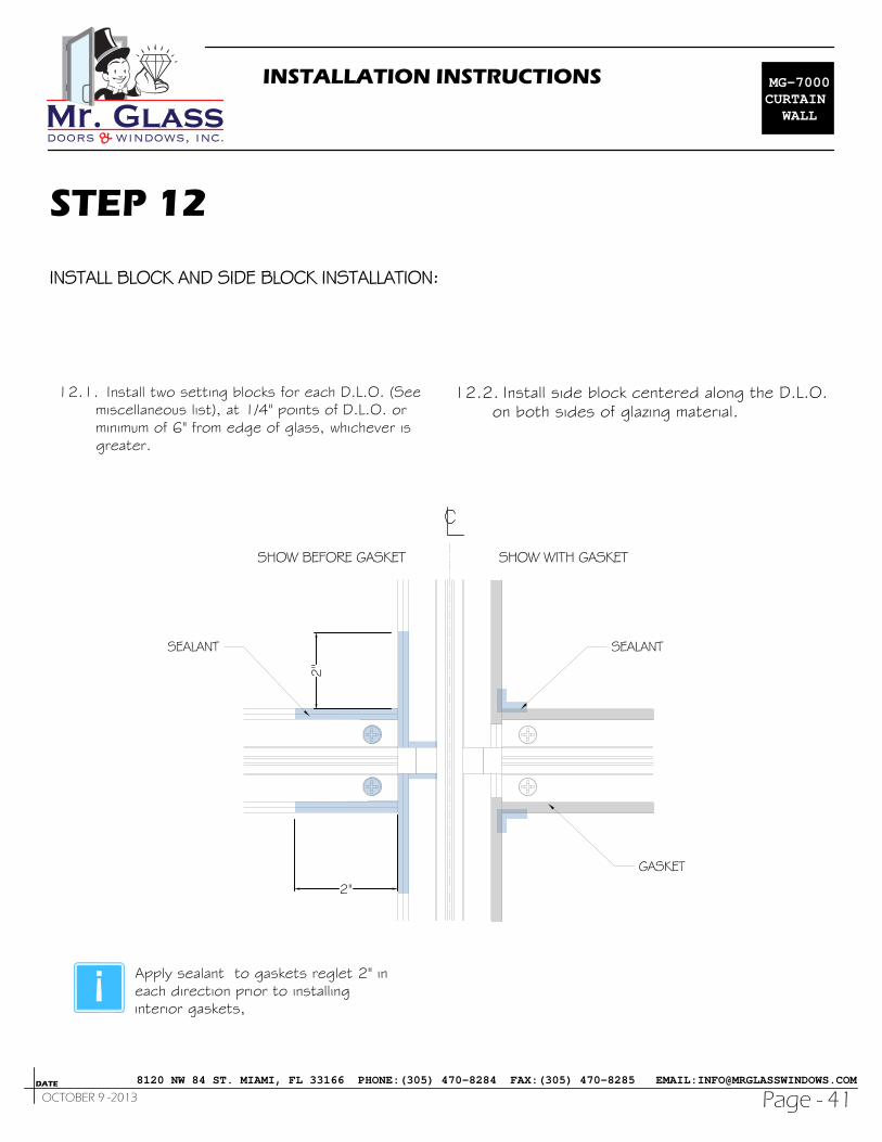
12.1. Install two setting blocks for each D.L.O. (Seemiscellaneous list), at 1/4" points of D.L.O. orminimum of 6" from edge of glass, whichever isgreater.
12.2. Install side block centered along the D.L.O.on both sides of glazing material.
2"
2"
Apply sealant to gaskets reglet 2" ineach direction prior to installinginterior gaskets,
MG-7000CURTAIN
WALL
8120 NW 84 ST. MIAMI, FL 33166 PHONE:(305) 470-8284 FAX:(305) 470-8285 EMAIL:[email protected]

INSTALLATION INSTRUCTIONS
Page -DATE
42OCTOBER 9 -2013
12.3. Apply silicone sealant into gasket reglet atcorner.
12.4. Review the cut of the gaskets.Vertical gasket: D.L.O. + 1 1/2".Horizontal gasket: D.L.O. + 3/16"
12.5. Install vertical gaskets firs, centered alongthe D.L.O.
12.6. Install horizontal glazing gasket next:Insert the gasket into the reglet at each endfirst.Snap the rest of the glazing gasket into thereglet starting at the center and worktowards each end.Pull the last 3" of each gasket away from thereglet.Reinsert the ends of the gaskets pressingthem firmly against the face of the mullions.
MG-7000CURTAIN
WALL
8120 NW 84 ST. MIAMI, FL 33166 PHONE:(305) 470-8284 FAX:(305) 470-8285 EMAIL:[email protected]

STEP 13
INSTALLATION INSTRUCTIONS
Page -DATE
43OCTOBER 9 -2013
13.1. User a retainer 4" long.
13.2. Temporary install a retainer glazing must beapplied at each glass edge 3" from the corner.
13.3. Use temporary glass retainers to hold glass inplace until pressure bars are installed.
13.4. Install vertical pressure plate bars bolts frombottom to top and horizontal pressure bars boltsfrom center outward.
13.5. Install gaskets into vertical and horizontalpressure plate.
13.6. Center horizontal pressure plate in D.L.O.leaving 1/16" gaps at each end.
13.7. Seal gaps at vertical/horizontal intersections,screw heads at top and bottom of verticalpressure plate.
MG-7000CURTAIN
WALL
8120 NW 84 ST. MIAMI, FL 33166 PHONE:(305) 470-8284 FAX:(305) 470-8285 EMAIL:[email protected]

INSTALLATION INSTRUCTIONS
Page -DATE
44OCTOBER 9 -2013
13.5. Install gaskets into vertical and horizontalpressure plate.
13.6. Center horizontal pressure plate in D.L.O.leaving 1/16" gaps at each end.
13.7. Seal gaps at vertical/horizontal intersections,screw heads at top and bottom of verticalpressure plate.
13.8. Install glass end attach a temporary pressureplate.
13.9. Apply sealant to the face of the joint pug justprior to installing pressure plate.
MG-7000CURTAIN
WALL
8120 NW 84 ST. MIAMI, FL 33166 PHONE:(305) 470-8284 FAX:(305) 470-8285 EMAIL:[email protected]

STEP 14
INSTALLATION INSTRUCTIONS
Page -DATE
45OCTOBER 9 -2013
14.1. Remove the temporary pressure plate endapply and tool sealant to completely seal gaps atthe pressure plate end.
14.2. Insert in the side cover of one cover splicesleeve.
MG-7000CURTAIN
WALL
8120 NW 84 ST. MIAMI, FL 33166 PHONE:(305) 470-8284 FAX:(305) 470-8285 EMAIL:[email protected]

INSTALLATION INSTRUCTIONS
Page -DATE
46OCTOBER 9 -2013
14.3. insert a backer rod between glass.
14.4. Apply masking tape to the edges of the glassand aluminum.
14.5. Apply structural silicone sealant into the cavitybetween the mullion and glass starting from thebottom end work towards the top.
MG-7000CURTAIN
WALL
8120 NW 84 ST. MIAMI, FL 33166 PHONE:(305) 470-8284 FAX:(305) 470-8285 EMAIL:[email protected]

INSTALLATION INSTRUCTIONS
Page -DATE
47OCTOBER 9 -2013
14.6. Care must be taken to prevent damage of facecovers during installation.
14.7. Snap on exterior covers end clean scrap pieceof lumber.
14.8. Start at one end and work down the verticaland across the horizontal.
14.9. The weeb holes located in the bottom side.
MG-7000CURTAIN
WALL
8120 NW 84 ST. MIAMI, FL 33166 PHONE:(305) 470-8284 FAX:(305) 470-8285 EMAIL:[email protected]

INT.EXT.
INT.
EXT.
G03
G01G01
1/4" GLASS
M44M44
SiliconeSilicone
Silicone
INT.EXT.
G01G01
G01G01
B03
HEAD / SILL
HORIZ.
VERTICALMULLION
SSG
G02
1" GLASS
HEAD / SILL
HORIZ.
VERTICALMULLION
SSG
INT.EXT.
INT.EXT.
INT.
EXT.
M44
Silicone
SiliconeSilicone
G01 G01
G01
B01
G02
G03
G01
G01
B01
G02
G01
M44
Backer rod
GLAZING DETAIL
INSTALLATION INSTRUCTIONS
Page -DATE
48OCTOBER 9 -2013
MG-7000CURTAIN
WALL
8120 NW 84 ST. MIAMI, FL 33166 PHONE:(305) 470-8284 FAX:(305) 470-8285 EMAIL:[email protected]

9/16" GLASS LMI
HEAD/ SILL
HORIZ.
VERTICALMULLION
SSG
G06
INT.EXT.
B05G02
G07
Silicone
G08
G06
B05G02
Silicone
INT.EXT.
G06 Silicone
G07
G07
INT.
EXT.
M44
M44Silicone
SiliconeSilicone
9/16" GLASS SMI
HEAD/ SILL
HORIZ.
VERTICALMULLION
SSG
G06
INT.EXT.
B05G02
G07
M44
G08
G06
B05G02
M44
INT.EXT.
G06 Silicone
G07
G07
INT.
EXT.
M44
M44Silicone
SiliconeSilicone
INSTALLATION INSTRUCTIONS
Page -DATE
49OCTOBER 9 -2013
MG-7000CURTAIN
WALL
8120 NW 84 ST. MIAMI, FL 33166 PHONE:(305) 470-8284 FAX:(305) 470-8285 EMAIL:[email protected]
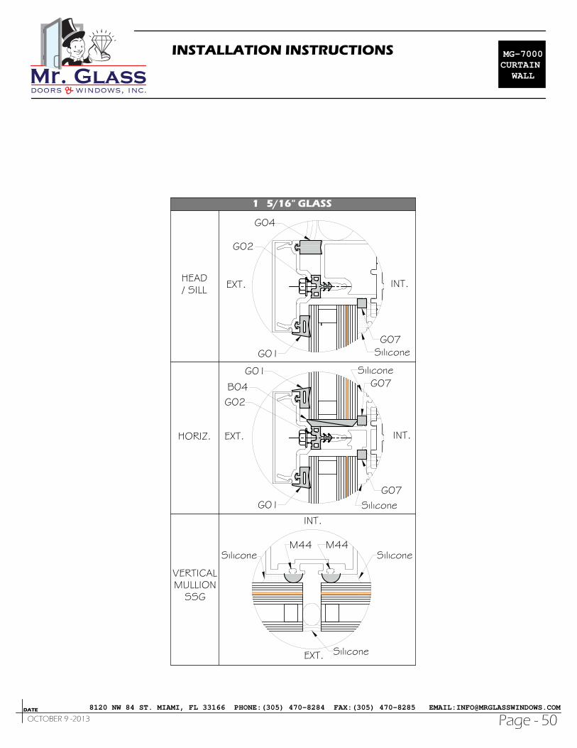
1 5/16" GLASS
HEAD/ SILL
HORIZ.
VERTICALMULLION
SSG
M44M44
INT.
EXT. Silicone
SiliconeSilicone
INT.EXT.
G01
G01
B04G02
SiliconeG07
SiliconeG07
G01 SiliconeG07
G04
G02
INT.EXT.
INSTALLATION INSTRUCTIONS
Page -DATE
50OCTOBER 9 -2013
MG-7000CURTAIN
WALL
8120 NW 84 ST. MIAMI, FL 33166 PHONE:(305) 470-8284 FAX:(305) 470-8285 EMAIL:[email protected]

PAG.DATEREVIEW
No.DESCRIPTION
INSTALLATION INSTRUCTIONS
Page -DATE
51
REVIEW
OCTOBER 9 -2013
MG-7000CURTAIN
WALL
8120 NW 84 ST. MIAMI, FL 33166 PHONE:(305) 470-8284 FAX:(305) 470-8285 EMAIL:[email protected]


![360 Brilliant and Instructive Endgames [Troitzky, 1961]](https://img.pdfslide.us/doc/110x75/5473b59eb4af9f08288b45b8/360-brilliant-and-instructive-endgames-troitzky-1961.jpg)