Embed Size (px)
Citation preview

BE-5-ME-SKIT-Ph5b1-F02-V2.0
LABORATORY PLAN - CAY 2019-20
17MEL57 Copyright ©2017. cAAS. All rights reserved.
Page # 1 / 26
SRI KRISHNA INSTITUTE OF TECHNOLOGY, BANGALORE
COURSE PLAN
Academic Year 2019-20
Program: BE – MECHANICAL ENGINEERING
Semester : 5
Course Code: 17MEL57
Course Title: FLUID MECHANICS & MACHINERY LAB
Credit / L-T-P: 2 / 1-0-2
Total Contact Hours: 36
Course Plan Author: Naveen Kumar Pattar/Dinesh P
Academic Evaluation and Monitoring Cell
No. 29, Chimney hills, Hesaraghatta Road, Chikkabanavara
BANGALORE-560090, KARNATAKA , INDIA
Phone / Fax :+91-08023721315/23721477, Web: www.skit.org.in
INSTRUCTIONS TO TEACHERS Classroom / Lab activity shall be started after taking attendance.
Ref No:

BE-5-ME-SKIT-Ph5b1-F02-V2.0
LABORATORY PLAN - CAY 2019-20
17MEL57 Copyright ©2017. cAAS. All rights reserved.
Page # 2 / 26
Attendance shall only be signed in the classroom by students.
Three hours attendance should be given to each Lab.
Use only Blue or Black Pen to fill the attendance.
Attendance shall be updated on-line & status discussed in DUGC.
No attendance should be added to late comers.
Modification of any attendance, over writings, etc is strictly prohibited.
Updated register is to be brought to every academic review meeting as per the COE.
Table of Contents
17MEL57:Fluid Mechanics and Machinery Lab ......................................... 4

BE-5-ME-SKIT-Ph5b1-F02-V2.0
LABORATORY PLAN - CAY 2019-20
17MEL57 Copyright ©2017. cAAS. All rights reserved.
Page # 3 / 26
A. LABORATORY INFORMATION ........................................................................... 4 1. Laboratory Overview ....................................................................................................................... 4
2. Laboratory Content .......................................................................................................................... 4
Expt# .................................................................................................................................................... 4
3. Laboratory Material ......................................................................................................................... 5
4. Laboratory Prerequisites: ................................................................................................................. 5
5. Content for Placement, Profession, HE and GATE ......................................................................... 6
B. Laboratory Instructions ............................................................................................. 6 1. General Instructions ......................................................................................................................... 6
2. Laboratory Specific Instructions ..................................................................................................... 6
C. OBE PARAMETERS ............................................................................................... 7 1. Laboratory Outcomes ...................................................................................................................... 7
2. Laboratory Applications .................................................................................................................. 8
3. Mapping And Justification............................................................................................................... 8
4. Articulation Matrix ........................................................................................................................ 10
5. Curricular Gap and Experiments ................................................................................................... 10
6. Experiments Beyond Syllabus ....................................................................................................... 10
D. COURSE ASSESSMENT ...................................................................................... 11 1. Laboratory Coverage ...................................................................................................................... 11
2. Continuous Internal Assessment (CIA) .......................................................................................... 11
E. EXPERIMENTS ..................................................................................................... 12 Experiment 01 : Calculate co-efficient of friction through pipes ...................................................... 12
Calculate co-efficient of friction through pipes ................................................................................. 12
Experiment 02 : Determination of minor losses in flow through pipes............................................. 13
Determination of minor losses in flow through pipes ....................................................................... 13
Experiment 03 :Application of momentum equation for determination of coefficient of impact
of jets on flat and curved blades ........................................................................................................ 15
Application of momentum equation for determination of coefficient of impact of jets on flat
and curved blades .............................................................................................................................. 15
Experiment 04 : Calibration of flow measuring devices Orifice meter, Nozzle ,Venturi meter ,
V-notch. ............................................................................................................................................. 16
Experiment 05 : Performance on hydraulic Turbines ........................................................................ 18
Experiment 06 : Performance hydraulic Pumps ................................................................................ 21
Performance hydraulic Pumps ........................................................................................................... 21
Experiment 07 : Performance test on a two stage Reciprocating Air compressor ............................ 23
Experiment 8 : Performance test on an Air Blower ........................................................................... 25
F. Content to Experiment Outcomes ........................................................................... 27 1. TLPA Parameters ........................................................................................................................... 27
2. Concepts and Outcomes: ............................................................................................................... 28
Note : Remove “Table of Content” before including in CP Book
Each Laboratory Plan shall be printed and made into a book with cover page
Blooms Level in all sections match with A.2, only if you plan to teach / learn at higher levels
17MEL57:Fluid Mechanics and Machinery Lab

BE-5-ME-SKIT-Ph5b1-F02-V2.0
LABORATORY PLAN - CAY 2019-20
17MEL57 Copyright ©2017. cAAS. All rights reserved.
Page # 4 / 26
A. LABORATORY INFORMATION
1. Laboratory Overview
Degree: BE Program: ME
Year / Semester : 3 / 5 Academic Year: 2019-20
Course Title: Fluid mechanics and machinery lab Course Code: 17MEL57
Credit / L-T-P: 2 / 1-0-2 SEE Duration: 180 Minutes
Total Contact Hours: 36 Hrs SEE Marks: 60Marks
CIA Marks: 40 Assignment ---
Lab. Plan Author: Naveen Kumar Pattar/Dinesh P Sign Dt :18/8/2019
Checked By: B M Krishne Gouda Sign Dt :
2. Laboratory Content
Expt
#
Title of the Experiments Lab
Hours
Concept Blooms
Level
1 Lab layout, calibration of instruments and standards to be discussed 3 - -
2 Determination of coefficient of friction of flow in a pipe. 3 Friction factors
by various c/s
pipes
L3
Apply
3 Determination of minor losses in flow through pipes 3 Losses through
pipes
L3
Apply
4 Application of momentum equation for determination of coefficient of
impact of jets on flat and curved blades
3 Impact jet L3
Apply
5 Calibration of flow measuring devices Orifice meter, Nozzle, Venturi
meter , V-notch.
3 Fluid flow L3
Apply
6 Performance on hydraulic Turbines
a. Pelton wheel
b. Francis Turbine
c. Kaplan Turbines
3 Performance
characteristics of
turbine
L3
Apply
7 Performance hydraulic Pumps
a. Single stage and Multi stage centrifugal pumps
b. Reciprocating pump
3 Performance
characteristics of
pumps
L3
Apply
8 Performance test on a two stage Reciprocating Air C
compressor
3 Characteristic
parameter for air
compressor
L3
Apply
9 Performance test on an Air Blower 3 Characteristic
parameter for
air blower
L3
Apply
3. Laboratory Material
Books & other material as recommended by university (A, B) and additional resources used by Laboratory teacher (C).
Expt. Details Expt. in
book
Availability
Text books
2-5 K.L.Kumar.“Engineering Fluid Mechanics” Experiments, Eurasia Publishing
House, 1997
In Library
6-9 Jagdish Lal, Hydraulic Machines, Metropolitan Bo
ok Co, Delhi, 1995
B Reference books
6-9 George E. Totten Victor J. De Negri “Handbook of Hydraulic Fluid Technology,
Second Edition, 2011
In Library

BE-5-ME-SKIT-Ph5b1-F02-V2.0
LABORATORY PLAN - CAY 2019-20
17MEL57 Copyright ©2017. cAAS. All rights reserved.
Page # 5 / 26
C Concept Videos or Simulation for Understanding 1 uorepc-nitk.vlabs.ac.in 2 https://www.youtube.com/watch? v=UDF448c6fOw 3 https://www.tutorialspoint.com/videotutorials/index.htm 4 https://skl.sh/practicalengineering3 5 https://www.tutorialspoint.com/videotutorials/index.htm Lecture By: Er. Himansu 6 - https://drive.google.com/open?id=1utMdeMujjiJwBuCD4r0fcflx0XAp4u9E ... 7 https://www.tutorialspoint.com/videotutorials/index.htm ... 8 https://amzn.to/2CWIed8
D Software Tools for Design - -
E Recent Developments for Research - -
F Others (Web, Video, Simulation, Notes etc.) - -
1 https://nptel.ac.in/courses/fluidmechanics.nit/
4. Laboratory Prerequisites:
Refer to GL01. If prerequisites are not taught earlier, GAP in curriculum needs to be addressed. Include in Remarks and
implement in B.5.
Students must have learnt the following Courses / Topics with described Content . . .
Expt. Lab. Code Lab. Name Topic / Description Sem Remarks Blooms
Level
1 17EME15 Elements Of
Mechanical
Engineering
Mechanical Properties of turbines 1 Plan Gap Course L2
2 17MEL57 Fluid mechanics Fluid properties, Fluid flows, variation
in fluid flows, turbulent and laminar
flow.
3 Plan Gap Course L2
5. Content for Placement, Profession, HE and GATE
The content is not included in this course, but required to meet industry & profession requirements and help students for
Placement, GATE, Higher Education, Entrepreneurship, etc. Identifying Area / Content requires experts consultation in
the area.
Topics included are like, a. Advanced Topics, b. Recent Developments, c. Certificate Courses, d. Course Projects, e.
New Software Tools, f. GATE Topics, g. NPTEL Videos, h. Swayam videos etc.
Expt. Topic / Description Area Remarks Blooms
Level
6 Fluid Mechanics and Performance of turbines GATE NPTEL Videos L3
B. Laboratory Instructions
1. General Instructions
SNo Instructions Remarks
1 Observation book and Lab record are compulsory.
2 Students should report to the concerned lab as per the time table.
3 After completion of the program, certification of the concerned staff in-charge in the
observation book is necessary.
4 Student should bring a notebook of 100 pages and should enter the readings
/observations into the notebook while performing the experiment.

BE-5-ME-SKIT-Ph5b1-F02-V2.0
LABORATORY PLAN - CAY 2019-20
17MEL57 Copyright ©2017. cAAS. All rights reserved.
Page # 6 / 26
5 The record of observations along with the detailed experimental procedure of the
experiment in the Immediate last session should be submitted and certified staff
member in-charge.
6 Should attempt all problems / assignments given in the list session wise.
7 It is responsibility to create a separate directory to store all the programs, so that
nobody else can read or copy.
8 When the experiment is completed, should disconnect the setup made by them, and
should return all the components/instruments taken for the purpose.
9 Any damage of the equipment or burn-out components will be viewed seriously either
by putting penalty or by dismissing the total group of students from the lab for the
semester/year
10 Completed lab assignments should be submitted in the form of a Lab Record in which
you have to write the algorithm, program code along with comments and output for
various inputs given
2. Laboratory Specific Instructions
SNo Specific Instructions Remarks
1 Students must attend the lab classes with ID cards and in the prescribed uniform.
2 Students must check if the components, instruments and machinery are
in working condition before setting up the experiment.
3 Power supply to the experimental set up/ equipment/ machine must be
switched on only after the faculty checks and gives approval fording the
experiment. Students must start to the experiment. Students must start
doing the experiments only after getting permissions from the faculty.
4 Students may contact the lab in charge immediately for any unexpected incident sand
emergency
5 The apparatus used for the experiments must be cleaned and returned to the
technicians, safely without any damage
6 Make sure, while leaving the lab after the stipulated time, that all the power
connections are switched off
C. OBE PARAMETERS
1. Laboratory Outcomes
Expt. Lab Code # COs / Experiment Outcome Teach.
Hours
Concept Instr
Method
Assessment
Method
Blooms’
Level
- - At the end of the experiment, the
student should be able to . . .
- - - - -
1 17MEL57.1 Calculate co-efficient of friction through
pipes
3 Friction
factors by
various c/s
pipes
Demonstr
ate
chalk and
Bord
Practical
record and IA
test
L3
Apply
2 17MEL57.2 Calculate different losses in pipes 3 Losses through
pipes
Demonstr
ate
chalk and
Bord
Practical
record and IA
test
L3
Apply
3 17MEL57.3 Calculate impact jet on planes 3 Impact jet Demonstr
ate
chalk and
Bord
Practical
record and IA
test
L3
Apply
4 17MEL57.4 Calculate total discharge through flow
measuring devises
9 Fluid flow Demonstr
ate
chalk and
Bord
Practical
record and IA
test
L3
Apply
5 17MEL57.5 Calculate flow pattern through the
hydraulic turbine
6 Performance
characteristics
of turbine
Demonstr
ate
chalk and
Practical
record and IA
test
L3
Apply

BE-5-ME-SKIT-Ph5b1-F02-V2.0
LABORATORY PLAN - CAY 2019-20
17MEL57 Copyright ©2017. cAAS. All rights reserved.
Page # 7 / 26
Bord
6 17MEL57.6 Illustrate flow pattern through the
hydraulic pumps
6 Performance
characteristics
of pumps
Demonstr
ate
chalk and
Bord
Practical
record and IA
test
L3
Apply
7 17MEL57.7 Calculate the characteristic performance
for air-compressor
3 Characteristic
parameter for
air compressor
Demonstr
ate
chalk and
Bord
Practical
record and IA
test
L3
Apply
8 17MEL57.8 Calculate the characteristic performance
for air-blower
3 Characteristic
parameter for
air blower
Demonstr
ate
chalk and
Bord
Practical
record and IA
test
L3
Apply
- Total 36 - - - -
Note: Identify a max of 2 Concepts per unit. Write 1 CO per concept.
2. Laboratory Applications
Expt. Application Area CO Level 1 Design of flow pipes CO1 L3 2 Power generating sector like turbine houses CO2 L3 3 Bernoulli’s Principle application areas CO3 L3 4 Jet fowl, calculations. Impulse turbine blade design CO4 L3 5 Discharge calculations in dams and channels CO5 L3 6 Power producing machines CO6 L3 7 Efficiency of turbines CO7 L3 8 Vehicle Air Blower testing CO8 L3 9 Hair drier CO9 L3
Note: Write 1 or 2 applications per CO.
3. Mapping And Justification
CO – PO Mapping with mapping Level along with justification for each CO-PO pair.
To attain competency required (as defined in POs) in a specified area and the knowledge & ability required to
accomplish it.
Expt. Mapping Mapping
Level
Justification for each CO-PO pair Lev
el
- CO PO - ‘Area’: ‘Competency’ and ‘Knowledge’ for specified ‘Accomplishment’ -
1 CO1 PO1 L2 ‘Engineering Knowledge:’Acquisition of Engineering Knowledge is required to
understand the different performance of flow in friction through pipes to accomplish
solutions to complex engineering problems in Mechanical Engineering.
L3
1 CO1 PO2 L3 ‘Problem Analysis’: Analyzing problems require knowledge of / understanding flow
in a friction to accomplish solutions to complex engineering problems in
Mechanical engineering.
L3
1 CO1 PO9 L2 ‘Individual work’:Coefficient of friction through flow in a pipe function can be find
effectively as an individual.
L3
2 CO2 PO1 L2 Engineering Knowledge:’Acquisition of Engineering Knowledge is required to
understand the different losses in the flow through pipes to accomplish solutions to
complex engineering problems in Mechanical Engineering.
L3
2 CO2 PO2 L3 ‘Problem Analysis’: Analyzing problems require knowledge of / understanding
different major and minor losses in pipes to accomplish solutions to complex
engineering problems in Mechanical engineering.
L3
2 CO2 PO9 L2 ‘Individual work’:Different losses in flow through pipe in a pipe function can be
find effectively as an individual.
L3
3 CO3 PO1 L3 ‘Engineering Knowledge:’Acquisition of Engineering Knowledge is required to L3

BE-5-ME-SKIT-Ph5b1-F02-V2.0
LABORATORY PLAN - CAY 2019-20
17MEL57 Copyright ©2017. cAAS. All rights reserved.
Page # 8 / 26
understand the coefficient of jet on plate to accomplish solutions to complex
engineering problems in Mechanical Engineering.
3 CO3 PO2 L3 ‘Problem Analysis’: Analyzing problems require knowledge of understanding
coefficient of discharge in a jet on plate to accomplish solutions to complex
engineering problems in Mechanical engineering.
L3
3 CO3 PO9 L2 ‘Individual work’:coefficient of discharge in a jet on plate in a pipe function can be
find effectively as an individual.
L3
4 CO4 PO1 L2 ‘Engineering Knowledge:’Acquisition of Engineering Knowledge is required to
understand the coefficient of discharge through flow measuring devices to
accomplish solutions to complex engineering problems in Mechanical Engineering.
L3
4 CO4 PO2 L3,L6,L4 ‘Problem Analysis’: Analyzing problems require knowledge of understanding
coefficient of discharge in an venturi, orifice meters through to accomplish
solutions to complex engineering problems in Mechanical engineering.
L3
4 CO4 PO9 L2 ‘Individual work’:coefficient of discharge in venturi and orifice in a pipe function
can be find effectively as an individual.
L3
5 CO5 PO1 L2 ‘Engineering Knowledge:’Acquisition of Engineering Knowledge is required to
understand the flow patterns in the different hydraulic turbines to accomplish
solutions to complex engineering problems in Mechanical Engineering.
L3
5 CO5 PO2 L3 ‘Problem Analysis’: Analyzing problems require knowledge of understanding
performance characteristics of different hydraulic turbines to accomplish solutions
to complex engineering problems in Mechanical engineering.
L3
5 CO5 PO9 L2 ‘Team work’:Performance characteristics of hydraulic turbine can be find
effectively as a team.
L3
6 CO6 PO1 L2 ‘Engineering Knowledge:’Acquisition of Engineering Knowledge is required to
understand the flow patterns in the different hydraulic pumps to accomplish
solutions to complex engineering problems in Mechanical Engineering.
L3
6 CO6 PO2 L3 ‘Problem Analysis’: Analyzing problems require knowledge of understanding
performance characteristics of different hydraulic pumps to accomplish solutions to
complex engineering problems in Mechanical engineering.
L3
6 CO6 PO9 L2 ‘Team work’:Performance characteristics of hydraulic pumps can be find
effectively as a team.
L3
7 CO7 PO1 L3 ‘Engineering Knowledge:’Acquisition of Engineering Knowledge is required to
understand the Performance of an air compressor to accomplish solutions to
complex engineering problems in Mechanical Engineering.
L3
7 CO7 PO2 L3 ‘Problem Analysis’: Analyzing problems require knowledge of understanding
performance characteristics of an air compressor to accomplish solutions to
complex engineering problems in Mechanical engineering.
L3
7 CO7 PO9 - ‘Team work’:Performance characteristics of air compressor can be find effectively
as a team.
L3
8 CO8 PO1 L2 ‘Engineering Knowledge:’Acquisition of Engineering Knowledge is required to
understand the Performance of an air blower to accomplish solutions to complex
engineering problems in Mechanical Engineering.
L3
8 CO8 PO2 L3 ‘Problem Analysis’: Analyzing problems require knowledge of understanding
performance characteristics of an air blower to accomplish solutions to complex
engineering problems in Mechanical engineering.
L3
8 CO8 PO9 L3 ‘Team work’:Performance characteristics of air blower can be find effectively as a
team.
L3
4. Articulation Matrix
CO – PO Mapping with mapping level for each CO-PO pair, with course average attainment.
- - Experiment Outcomes Program Outcomes -
Expt. CO.# At the end of the experiment PO PO PO PO PO PO PO PO PO PO PO PO PS PS PS Lev

BE-5-ME-SKIT-Ph5b1-F02-V2.0
LABORATORY PLAN - CAY 2019-20
17MEL57 Copyright ©2017. cAAS. All rights reserved.
Page # 9 / 26
student should be able to . . . 1 2 3 4 5 6 7 8 9 10 11 12 O1 O2 O3 el
1 17MEL57.1 Calculate co-efficient of friction
through pipes
2 3 - - - - - - 2 - - - - - - L3
2 17MEL57.2 Calculate different losses in pipes 2 3 - - - - - - 2 - - - - - - L3
3 17MEL57.3 Calculate impact jet on planes 2 2 - - - - - - 2 - - - - - - L3
4 17MEL57.4 Calculate total discharge through
flow measuring devises
2 3 - - - - - - 2 - - - - - - L3
5 17MEL57.5 Calculate flow pattern through the
hydraulic turbine
2 3 - - - - - - 2 - - - - - - L3
6 17MEL57.6 Illustrate flow pattern through the
hydraulic pumps
2 2 - - - - - - 2 - - - - - - L3
7 17MEL57.7 Calculate the characteristic
performance for air-compressor
2 2 - - - - - - 2 - - - - - - L3
8 17MEL57.8 Calculate the characteristic
performance for air-blower
2 2 - - - - - - 2 - - - - - - L3
- 17MEL57 Average attainment (1, 2, or 3) 2 2.5 2 -
- PO, PSO 1.Engineering Knowledge; 2.Problem Analysis; 3.Design / Development of Solutions; 4.Conduct
Investigations of Complex Problems; 5.Modern Tool Usage; 6.The Engineer and Society;
7.Environment and Sustainability; 8.Ethics; 9.Individual and Teamwork; 10.Communication;
11.Project Management and Finance; 12.Life-long Learning; S1.Software Engineering; S2.Data
Base Management; S3.Web Design
5. Curricular Gap and Experiments
Topics & contents not covered (from A.4), but essential for the course to address POs and PSOs.
Expt Gap Topic Actions Planned Schedule Planned Resources Person PO Mapping
1 Flow Measuring Devices
concept
Seminar 15/10/2019 Self PO2
2 Air Blower Working
Principle
NPTEL Videos 4/11/2019 - PO2
Note: Write Gap topics from A.4 and add others also.
6. Experiments Beyond Syllabus
Topics & contents required (from A.5) not addressed, but help students for Placement, GATE, Higher Education,
Entrepreneurship, etc.
Expt Gap Topic Actions Planned Schedule Planned Resources Person PO Mapping
1 Analysis of orifice and
venturi meter
NPTEL Videos 15/10/2019 - PO2
D. COURSE ASSESSMENT
1. Laboratory Coverage
Assessment of learning outcomes for Internal and end semester evaluation. Distinct assignment for each student. 1
Assignment per chapter per student. 1 seminar per test per student.
Unit Title Teachin
g Hours
No. of question in Exam CO Levels
CIA-1 CIA-2 CIA-3 Asg-1 Asg-2 Asg-3 SEE
1 Lab layout, calibration of instruments
and standard
s to be discussed
03 1 - - - - - 1 CO1 L2
2 Determination of coefficient of friction
of flow in
a pipe.
03 1 - - - - - 1 CO2 L3
3 Determination of minor losses in flow
through pipes
03 1 - - - - - 1 CO3 L3
4 Application of momentum equation for
determination of coefficient of impact
of jets on flat and curved blades
03 1 - - - - - 1 CO4 L3
BE-5-ME-SKIT-Ph5b1-F02-V2.0
LABORATORY PLAN - CAY 2019-20
17MEL57 Copyright ©2017. cAAS. All rights reserved.
Page # 10 / 26
5 Calibration of flow measuring devices
Orifice meter, Nozzle,
Venturi meter , V-notch.
06 - 2 - - - - 2 CO5 L3
6 Performance on hydraulic Turbines
a. Pelton wheel
b. Francis Turbine
c. Kaplan Turbines
06 - 2 - - - - 2 CO6 L3
7 Performance hydraulic Pumps
a. Single stage and Multi stage
centrifugal pumps
b. Reciprocating pump
06 - - 2 - - - 2 CO7 L3
8 Performance test on a two stage
Reciprocating Air C
compressor
03 - - 1 - - - 1 CO8 L3
9 Performance test on an Air Blower 03 - - 1 - - - 1 CO9 L3
- Total 36 4 4 4 - - - 12 L3
2. Continuous Internal Assessment (CIA)
Assessment of learning outcomes for Internal exams. Blooms Level in last column shall match with A.2.
Evaluation Weightage in Marks CO Levels
CIA Exam – 1 40 CO1, CO2, CO3, CO4 L3
CIA Exam – 2 40 CO5, CO6 L3
CIA Exam – 3 40 CO7, CO8,CO9 L3
- - -
Other Activities – define –
Slip test
- - -
Final CIA Marks 40 C01-CO9 L3
-
SNo Description Marks
1 Observation and Weekly Laboratory Activities 10 Marks
2 Record Writing / Viva 15 Marks for each Expt
3 Internal Exam Assessment 15 Marks
4 Internal Assessment 40 Marks
5 SEE 60 Marks
- Total 100 Marks
E. EXPERIMENTS
Experiment 01 : Calculate co-efficient of friction through pipes
- Experiment No.: 1 Marks 15 Date
Planned
Date
Conducted
1 Title Calculate co-efficient of friction through pipes
2 Course Outcomes Calculate co-efficient of friction through pipes
3 Aim Determine coefficient of friction for pipes and head loss in pipe friction
4 Material / Equipment
Required
Pipe friction apparatus , stop watch
5 Theory, Formula,
Principle, Concept
To find co-efficient of friction,f=hf*2gd/alv2 , Friction factors by various c/s pipes
6 Procedure, Program, step 1: Before starting flow through pipes the initial manometer reading is taken.
BE-5-ME-SKIT-Ph5b1-F02-V2.0
LABORATORY PLAN - CAY 2019-20
17MEL57 Copyright ©2017. cAAS. All rights reserved.
Page # 11 / 26
Activity, Algorithm,
Pseudo Code
step 2: Then the fluid is allowed to flow through pipes.
step 3: Then the manometer reading on the pipe is taken down.
Step 4: Take the time required for 100 mm rise in water level in measuring tank
step 5:Take at least 3 readings.
step 6: Above procedure is repeated for different discharges
7 Block, Circuit, Model
Diagram, Reaction
Equation, Expected
Graph
- v=Q/a,hf=4lv
2/2gd, f=hf2gd/4lv
2
8 Observation Table,
Look-up Table, Output Diameter Of pipe
in mm
Trial No
Manometer
reading in cm
Frictional
head loss hf =
(H1 ±
H2) * 12.6 100
in m
Time required
for 100 mm rise
in water
level (t) in sec
Discharge of
Head Q = (A x
h) t
in
m3/sec
Velocity of
Water fow
V= Q a
in m3/sec
Coefficient of friction f = hf * 2gd
LV 2
H1 H2
For
22 mm
1
2
3
For
17 mm
1
2 3
9 Sample Calculations -Frictional Head Loss (hf) = ( (h1+ h2 ) / 100) x 12.6
-Velocity V= Q/a in m/sec
- f x L x V2
hf = --------------------
2gd
- hf x 2gd
f = -------------------
L x V2
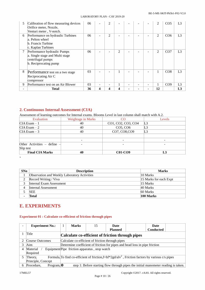
10 Graphs, Outputs
-
Y
X
VELOCITY (m/sec)
HE
AD
LO
SS
(m)
®
IDEAL GRAPH OF FRICTION IN PIPES (FOR DIA 17 mm)
11 Results & Analysis a) Head loss due to pipe friction for ø 22 mm pipe is hf =
………m
b) Coefficient of friction for diameter 22 mm pipe is = ----------- 12 Application Areas Calculate pressure drop velocities and Reynolds Number applications
13 Remarks
14 Faculty Signature with
Date

BE-5-ME-SKIT-Ph5b1-F02-V2.0
LABORATORY PLAN - CAY 2019-20
17MEL57 Copyright ©2017. cAAS. All rights reserved.
Page # 12 / 26
Experiment 02 : Determination of minor losses in flow through pipes
- Experiment No.: 1 Marks 15 Date
Planned
Date
Conducted
1 Title Determination of minor losses in flow through pipes
2 Course Outcomes Calculate different losses in pipes
3 Aim To determine different losses due to pipe fitting
4 Material / Equipment
Required
Set of pipe fitting apparatus, stop watch
5 Theory, Formula,
Principle, Concept
Losses through pipes, Hx=(h1+h2/1000)*12.6, hem=(v1-v2)2/2g
h6 Procedure, Program,
Activity, Algorithm,
Pseudo Code
step 1: Before starting flow through pipes the initial manometer reading is taken.
step 2: Then the fluid is allowed to flow through pipes.
step 3: Then the manometer reading on the pipe is taken down.
step 4:Take the time required for 100 mm rise in water level in measuring tank
step 5:Take at least 3 readings.
step 6: Above procedure is repeated for different discharges
7 Block, Circuit, Model
Diagram, Reaction
Equation, Expected
Graph
Head loss (Elbow)
0.25 v2
he = ------------
2g
Head loss ( Contraction)
0.5 v2
hc = ------------
2g
Head loss ( Enlargement)
(v1-v2)2
hen = ------------
2g 8 Observation Table,
Look-up Table,
Output
Type of
fitting
Trail
Nos
Manomete
r reading
in cm
Differentia
l
Head of Manomete
r
Time
required
for 100 mm rise of
water level
Discharge
Q =A x h t
in m3/sec
Area of
correspond
ing Pipe ‘a’
in m2
Velocity of
Flow
V in m/sec
Frictional
head loss
hf in m

BE-5-ME-SKIT-Ph5b1-F02-V2.0
LABORATORY PLAN - CAY 2019-20
17MEL57 Copyright ©2017. cAAS. All rights reserved.
Page # 13 / 26
H=(h1±h2)*
12.6 100
in m
(t) in sec
h1 h2
BEND
1
2
3
ELBOW
1
2 3
CONTRACTION
1
2 3
ENLARG
EMENT
1 2
3
a1 a2
9 Sample Calculations 1) Heat lost due to Friction in m of water
H = ( H1+H2 /100) x12.6 2) Velocity V = Q/a in m/s
10 Graphs, Outputs
11 Results & Analysis 1. Head loss due to friction in bend hb = -----------------
2. Head loss due to friction in elbow he = -----------------
3. Head loss due to friction in sudden contraction hc = -----------------
4. Head loss due to friction in sudden enlargement he = -----------------
12 Application Areas Design of flow pipes
13 Remarks
14 Faculty Signature
with Date
Experiment 03 :Application of momentum equation for determination of coefficient of impact of jets on flat and
curved blades
- Experiment No.: 1 Marks 15 Date
Planned
Date
Conducted
1 Title Application of momentum equation for determination of coefficient of impact of jets
on flat and curved blades
2 Course Outcomes Calculate impact jet on planes
3 Aim Determination of force developed by impact of jet on vanes 4 Material / Equipment
Required Impact of jet apparatus , Standard dead weights, Stop watch
Theory, Formula,
Principle, Concept Coefficient impact of jet K = F act
F the 6 Procedure, Program,
Activity, Algorithm,
Pseudo Code
Step 1: First balance the lever mechanism to zero.
Step 2: Again balance the lever mechanism by loading weights on the other side
lever mechanism.
Step 3: Take the time required for 100mm raise in water level of measuring tank
Step 4: Above procedure is repeated for different discharges.
Step 5: Thus calculate the impact forces.
step 6: Above procedure is same for inclined plate.

BE-5-ME-SKIT-Ph5b1-F02-V2.0
LABORATORY PLAN - CAY 2019-20
17MEL57 Copyright ©2017. cAAS. All rights reserved.
Page # 14 / 26
7 Block, Circuit, Model
Diagram, Reaction
Equation, Expected
Graph
W * X W = loaded weight in N
F act = -------------- N X = 480mm = 0.48m
Y Y = 185mm = 0.185m
8 Observation Table,
Look-up Table,
Output
Sl No
Weights Time
require
d for
100m
m rise
of
water
level (
t) in
sec
Discharge
of jet Q
in m3/sec
Velocity
V in m/s
Theoretica
l force Fthe
in N
Actual
force Fact in N
Coeffi
cient
impact
of jet
In
Grams
In
Newto
n
1
2
9 Sample Calculations δw * a * v2
F the = ------------------- * sin2ө (in the direction of flow)
g
δw * a * v2
F the = ------------------- * sin2ө (in the direction normal to flow).
10 Graphs, Outputs
o ® VELOCITY (m/sec)
DISC
HARG
E (Q
) IN
(m3/
sec)
IDEAL GRAPH OF IMPACT OF JET
11 Results & Analysis The coefficient of impact of a jet striking a flat plate is = ------------------- 12 Application Areas Power generating sector like turbine houses
13 Remarks
14 Faculty Signature
with Date
Experiment 04 : Calibration of flow measuring devices Orifice meter, Nozzle ,Venturi meter , V-notch.
- Experiment No.: 1 Marks 15 Date
Planned
Date
Conducted

BE-5-ME-SKIT-Ph5b1-F02-V2.0
LABORATORY PLAN - CAY 2019-20
17MEL57 Copyright ©2017. cAAS. All rights reserved.
Page # 15 / 26
1 Title Calibration of flow measuring devices Orifice meter, Nozzle,
Venturi meter , V-notch.
2 Course Outcomes Calculate total discharge through flow measuring devises
3 Aim To measure the discharge through venturi meter & orifice meter.
4 Material / Equipment
Required Set up of venturi meter & orifice meter, stop watch.
5 Theory,Formula,
Principle, Concept
Q act
Cd = -------------
Q the
6 Procedure, Program,
Activity, Algorithm,
Pseudo Code
Step 1: First open the by pass, pipe valves completely and close all the manometer tapings
Step 2: Start the motor.
Step 3: First take the discharge through venturi meter and take the following readings a)
manometer reading) time required for 100mm rise in water level.
Step 4: For taking discharge through venturi meter –a) close the orifice valve and open the
venturi meter valve completely .b) open the manometer, tapping of venturi meter c) control
the flow with help of by pass valve provided.
Step 5: Repeat the above procedure for different discharges
step 6: Take at least 3 or 4 readings.
7 Block, Circuit, Model
Diagram, Reaction
Equation, Expected
Graph
1 Theoretical discharge :-
a1* a2
Qthe = ----------------- x √(2gH ) = C √H in m3 / sec
√(a12
– a2 8 Observation Table,
Look-up Table,
Output
Sl
No
Manometer Reading
in cm
Head of
water
through
venturimet
er /
Time taken
for 100 mm
rise of
water level
(t)
Theoretical
Discharge
Qthe
in m3/sec
Actual
Discharge
Qact
in m3/sec
Coefficient
Of
discharge
Cd h1 h2

BE-5-ME-SKIT-Ph5b1-F02-V2.0
LABORATORY PLAN - CAY 2019-20
17MEL57 Copyright ©2017. cAAS. All rights reserved.
Page # 16 / 26
orifice
meter
H= h1+h2 x
12.6 100
in m
in sec
1
9 Sample Calculations
10 Graphs, Outputs
®ACTUAL DISCHARGE (m3/sec)
®H
EA
D (
H)
in m
0
IDEAL GRAPH OF VENTURIMETER
®H
EA
D (
H)
in m
0 COEFFICIENT DISCHARGE (Cd)
11 Results & Analysis The given venturi meter has been calibrated & the average coefficient
of discharge is found to be Cd (avg) = ………..
12 Application Areas Bernoulli’s Principle application areas
13 Remarks
14 Faculty Signature
with Date
Experiment 05 : Performance on hydraulic Turbines
a. Pelton wheel
b. Francis Turbine
c. Kaplan Turbines
- Experiment No.: 1 Marks 15 Date
Planned
Date
Conducted
1 Title Performance on hydraulic Turbines
2 Course Outcomes
Calculate flow pattern
through the hydraulic
turbine
Calculate flow pattern through the hydraulic turbine
3 Aim Performance testing of pelton wheel turbine
Performance testing of Francis turbine 4 Material / Equipment
Required Experimental setup for Pelton wheel turbine ,Standard weights, Tachometer.
5 Theory, Formula,
Principle, Concept
Out put power
η = ----------------------- x 100
Input power
2 .π .N. T * 9.81
O/P = -------------------------- KW
60 * 1000

BE-5-ME-SKIT-Ph5b1-F02-V2.0
LABORATORY PLAN - CAY 2019-20
17MEL57 Copyright ©2017. cAAS. All rights reserved.
Page # 17 / 26
6 Procedure, Program,
Activity, Algorithm,
Pseudo Code
Step 1: Keep the gate valve in the pipe line open and start the motor.
Step 2: Gradually close the gate valve & apply certain load.
Step 3: Gradually close the gate valve & bring the speed of runner to rotated valve.
Step 4: Note the following readings
a) pressure gauges reading.
b) spring balance reading.
c) speed of the runner.
Step 5: Take at least 6-7 readings, keeping speed of the turbine constant.
step 6: Tabulate the readings neatly.
7 Block, Circuit, Model
Diagram, Reaction
Equation, Expected
Graph
H = Px10
Cd * a1 * a2
Q = ----------------------- x √ (2gh).
√ (a12
-a22)
δw * g * Q * H
IP = -----------------------
1000 8 Observation Table,
Look-up Table,
Output
Sl No Load
added
(W)
Pressure
gauge
reading of
Head of
orificemet
er
Inlet
pressure
Of
Head of
turbine

BE-5-ME-SKIT-Ph5b1-F02-V2.0
LABORATORY PLAN - CAY 2019-20
17MEL57 Copyright ©2017. cAAS. All rights reserved.
Page # 18 / 26
orificemet
er
turbine
W in
kgs
W
in N
(w x
9.81)
P1
(kg/c
m2)
P2
(kg/c
m2)
h =(p1~ p2
)10
m of water
P
(kg/cm2)
H=(Px10)
in m
9 Sample Calculations 10 Graphs, Outputs
®
E
FF
ICIE
NC
Y (
) IN
(
)
h%
O DISCHARGE ' Q' (M3/SEC)
OU
T P
UT
IN
(K
W)
®
O OUT PUT IN (KW)
IDEAL GRAPH OF PELTON W HEEL
[ FOR CONSTANT HEAD ]
® ACTUAL DISCHARGE (m3/sec)
INP
UT
IN
(K
W)
0 ®
0 OUTPUT (KW)
EF
FIC
IEN
CY
(h
)%
IN(
)
IDEAL GRAPH OF FRANCIS TURBINE
[ FOR CONSTANT SPEED ]
11 Results & Analysis The experiment to study the characteristics of the pelton wheel has been
conducted successfully and the average efficiencies
1. At constant head η avg = …………in (%)
2. At constant speed η avg = …………in (%)
12 Application Areas Power plants
13 Remarks
14s Faculty Signature
with Date

BE-5-ME-SKIT-Ph5b1-F02-V2.0
LABORATORY PLAN - CAY 2019-20
17MEL57 Copyright ©2017. cAAS. All rights reserved.
Page # 19 / 26
Experiment 06 : Performance hydraulic Pumps
a. Single stage and Multi stage centrifugal pumps
b. Reciprocating pump
- Experiment No.: 1 Marks 15 Date
Planned
Date
Conducted
1 Title Performance hydraulic Pumps
2 Course Outcomes illustrate flow pattern through the hydraulic pumps
3 Aim *To determine the performance of single stage centrifugal pump.
* 4 Material / Equipment
Required Single stage centrifugal pump setup, stop watch , Tacho meter.
5 Theory, Formula,
Principle, Concept 4) Efficiency (η)
Out put power
η = --------------------- x 100 in (%)
Input power
6 Procedure, Program,
Activity, Algorithm,
Pseudo Code
Step 1: Prime the pump with water.
Step 2:Start the motor
Step 3: Note down the following readings.
a) Vacuum gauge reading.
b) Pressure gauge reading.
c) Time required for 10 flash of energy meter.
d) Time required for 100 mm of water level in measuring tank
Step 4: Vary the position of gate valve in delivery pipe.
Step 5: Repeat the above procedure for different discharges.
7 Observation Table,
Look-up Table,
Output
Sl
No
Suction
head
(Hs)
Delivery
head
(Hd)
Tota
l
head H=(
Hs+
Hd)+
Z In m
Tim
e
requ
ired
for
10
flash
es
(T)
in
sec
Tim
e
requ
ired
for1
00m
m
rise
of
wate
r
level
in
mea
suri
ng
tank
(t) in
sec
Disc
harg
e
(Q)
in
m3/s
ec
Inpu
t
pow
er
(IP)
in KW
Out
put
pow
er
(
OP)
in KW
Effic
ienc
y
η in
(%) mm
of
Hg
m of
H2O
Kg/c
m2
m of
H2
O

BE-5-ME-SKIT-Ph5b1-F02-V2.0
LABORATORY PLAN - CAY 2019-20
17MEL57 Copyright ©2017. cAAS. All rights reserved.
Page # 20 / 26
1
8 Block, Circuit, Model
Diagram, Reaction
Equation, Expected
Graph
9 Sample Calculations
10 Graphs, Outputs
® HEAD (m)0x
y
INP
UT
(K
W)
DEAL GRAPH OF CENTRIFUGAL PUMPI
BE-5-ME-SKIT-Ph5b1-F02-V2.0
LABORATORY PLAN - CAY 2019-20
17MEL57 Copyright ©2017. cAAS. All rights reserved.
Page # 21 / 26
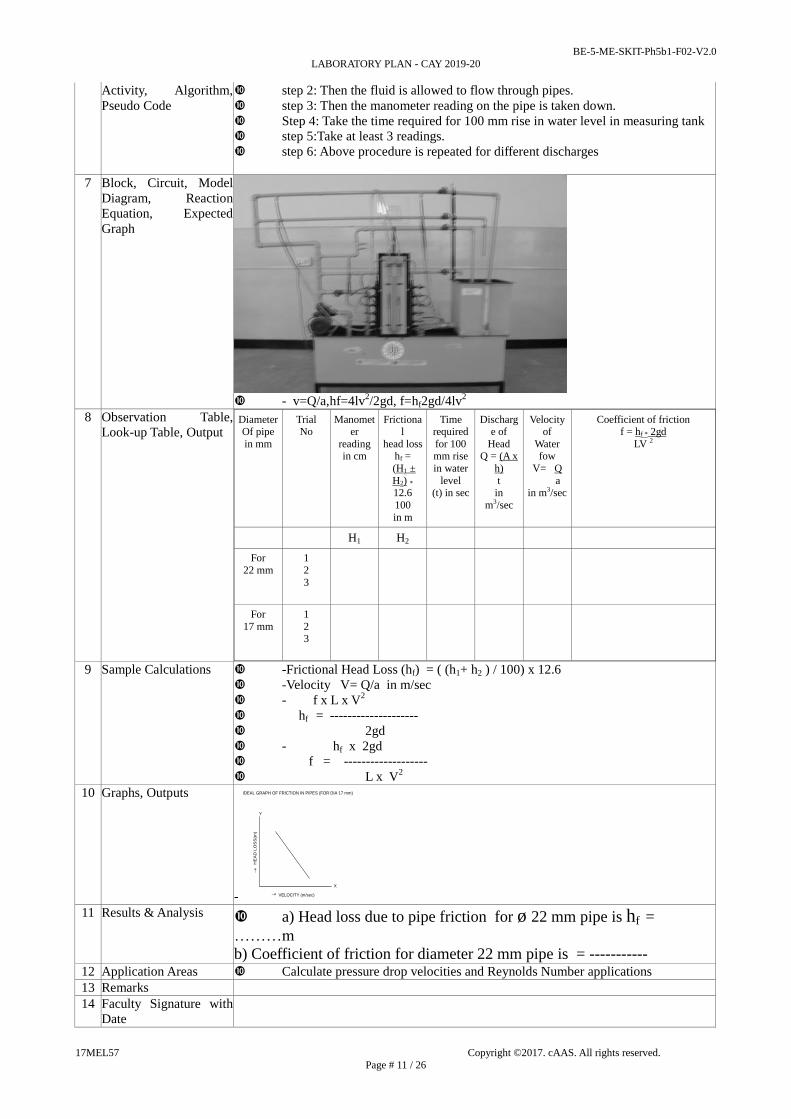
TOTAL HEAD®0 (m)®
X
Y
IDEAL GRAPH OF RECIPROCATING PUMP
TOTAL HEAD®0 (m)X
Y
Qa
ct
IN (
m3
/se
c)
EF
FIC
IEN
CY
(
)
IN (
)h
%®
11 Results & Analysis The overall performance of centrifugal pump η(avg) = ……… (%)
The overall performance of reciprocating pump η avg = ……… (%) 12 Application Areas Power plants
13 Remarks
14 Faculty Signature
with Date
Experiment 07 : Performance test on a two stage Reciprocating Air compressor
- Experiment No.: 1 Marks 15 Date
Planned
Date
Conducted
1 Title Performance test on a two stage Reciprocating Air C
compressor
2 Course Outcomes Calculate the characteristic performance for air-compressor
3 Aim To determine the performance test of single stage Reciprocating pump 4 Material / Equipment
Required Experimental setup for two stage air compressor, Stop watch.
5 Theory, Formula,
Principle, Concept
Volumetric efficiency ηv = Qact x 100 in (%)
Qthe 6 Procedure, Program,
Activity, Algorithm,
Pseudo Code
Step 1: Check connection and ensure direction of rotation of compressor.
9) Tabulate all the readings and calculate Isothermal efficiency.
Step 2: Close shutoff valve.
Step 3: Fill manometer with water.
Step 4:Start the motor and observe pressure on the pressure gauge.
Step 5:Once reaches 1kg/Sq. cm, adjust the valve opening for the same pressure.
Step 6 Note down the reading of manometer.
Step 7 Note down the time require for “n” flash of the energy meter. Step 8 Repeat the experiment for 2kg/Sq. cm, 3kg/ Sq.cm etc., Pressure.

BE-5-ME-SKIT-Ph5b1-F02-V2.0
LABORATORY PLAN - CAY 2019-20
17MEL57 Copyright ©2017. cAAS. All rights reserved.
Page # 22 / 26
7 Block, Circuit, Model
Diagram, Reaction
Equation, Expected
Graph
8 Observation Table,
Look-up Table,
Output
Sl
No.
Manom
eter
head of
water
Hw =
H1~H2 1000
in m
Manom
eter
head of
air
Ha =
Hw x ρw ρa
in m
Air
mass
flow
rate at
NTP
(V1) in
m3/min
Isother
mal
Horse
power
Iso Hp
in KW
Input
horse
power
IHP
in KW
Isother
mal
efficien
cy
ηISO in (%)
Theoret
ical
volume
swept
by
compre
ssor
Qthe
in
m3/sec
Actual
volume
swept
by
compre
ssor
Qact
in
m3/sec
Free air
delivere
d
by the
compre
ssor
FAD in
m3/s
Volume
tric
Efficien
cy
ηvol = Qact Qthe
in (%)
9 Sample Calculations
10 Graphs, Outputs
TOTAL HEAD®0 (m)
®
X
Y
IDEAL GRAPH OF RECIPROCATING PUMP
TOTAL HEAD®0 (m)X
Y
Qa
ct
IN (
m3
/se
c)
EF
FIC
IEN
CY
(
)
IN (
)h
%®
11 Results & Analysis The overall performance of reciprocating pump η avg = ……… (%) 12 Application Areas Vehicle Air Blower testing
13 Remarks
14 Faculty Signature
with Date
Experiment 8 : Performance test on an Air Blower
- Experiment No.: 1 Marks 15 Date
Planned
Date
Conducted
1 Title Performance test on an Air Blower

BE-5-ME-SKIT-Ph5b1-F02-V2.0
LABORATORY PLAN - CAY 2019-20
17MEL57 Copyright ©2017. cAAS. All rights reserved.
Page # 23 / 26
2 Course Outcomes Calculate the characteristic performance for air-blower To study the performance test of a
centrifugal air blower of different inlet positions
3 Aim To study the performance test of a centrifugal air blower of different inlet
positions
4 Material / Equipment
Require Air blower test rig, stop watch.
5 Theory, Formula,
Principle, Concept
Power
η = O/P Power X 100 in (%)
I/P Power
6 Procedure, Program,
Activity, Algorithm,
Pseudo Code
Step 1: Connected the input power for console to 3hp AC supply with neutral and earth
step 2: Keep all the switches/controls off/zero
step 3: Switch on the mains and observe the light indications are ON beneath the console
Step 4:Switch on the console mains ON
Step 5:Switch on the instrumentation
step 6:Keep the inlet valve open fully
step 7:Switch on the starter so that the motor speed builds up to the constant rpm
step 8: Null balance the torque arm using hand wheel
step 9:take down the readings namely, blower speed ,flow, head, energy meter reading,
casing pressure distribution as per the table of readings
step 10:Repeat the experiment for different types of impeller and for different gate opening
step 11:After the readings are taken, switch off motor and electrical mains.
7 Block, Circuit, Model
Diagram, Reaction
Equation, Expected
Graph
Input = n x 3600 x ηmotor in KW
N x T
8 Observation Table,
Look-up Table,
Output
Sl NO Manometer
Reading
Outlet pitot
tube
Reading
Orifice meter
Reading
Temperature
(t) in oC Time taken for
5 revs of energy
Meter
( T ) in sec
h1 cm
h2 cm
H1 m
h1 cm
h2 cm
H2 m
h1 cm
h2 cm
hw
m
Inlet
or
room
temp
Outlet
temp
BE-5-ME-SKIT-Ph5b1-F02-V2.0
LABORATORY PLAN - CAY 2019-20
17MEL57 Copyright ©2017. cAAS. All rights reserved.
Page # 24 / 26
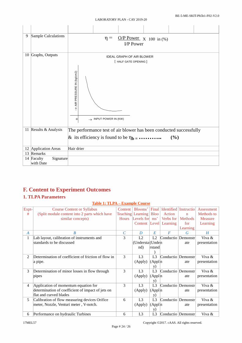
9 Sample Calculations η = O/P Power X 100 in (%)
I/P Power
10 Graphs, Outputs
® INPUT POWER IN (KW)
AIR
PR
ES
SU
RE
IN
(kg
/cm
2)
o
IDEAL GRAPH OF AIR BLOWER
[ HALF GATE OPENING ]
11 Results & Analysis The performance test of air blower has been conducted successfully
& its efficiency is found to be ηb = ……….. (%)
12 Application Areas Hair drier
13 Remarks
14 Faculty Signature
with Date
F. Content to Experiment Outcomes
1. TLPA Parameters
Table 1: TLPA – Example Course
Expt-
#
Course Content or Syllabus
(Split module content into 2 parts which have
similar concepts)
Content
Teaching
Hours
Blooms’
Learning
Levels for
Content
Final
Bloo
ms’
Level
Identified
Action
Verbs for
Learning
Instructio
n
Methods
for
Learning
Assessment
Methods to
Measure
Learning
A B C D E F G H
1 Lab layout, calibration of instruments and
standards to be discussed
3 L2
(Understa
nd)
L2
(Unde
rstand
)
Conductio
n
Demonstr
ate
Viva &
presentation
2 Determination of coefficient of friction of flow in
a pipe.
3 L3
(Apply)
L3
(Appl
y)
Conductio
n
Demonstr
ate
Viva &
presentation
3 Determination of minor losses in flow through
pipes
3 L3
(Apply)
L3
(Appl
y)
Conductio
n
Demonstr
ate
Viva &
presentation
4 Application of momentum equation for
determination of coefficient of impact of jets on
flat and curved blades
3 L3
(Apply)
L3
(Appl
y)
Conductio
n
Demonstr
ate
Viva &
presentation
5 Calibration of flow measuring devices Orifice
meter, Nozzle, Venturi meter , V-notch.
6 L3
(Apply)
L3
(Appl
y)
Conductio
n
Demonstr
ate
Viva &
presentation
6 Performance on hydraulic Turbines 6 L3 L3 Conductio Demonstr Viva &

BE-5-ME-SKIT-Ph5b1-F02-V2.0
LABORATORY PLAN - CAY 2019-20
17MEL57 Copyright ©2017. cAAS. All rights reserved.
Page # 25 / 26
a. Pelton wheel
b. Francis Turbine
c. Kaplan Turbines
(Apply) (Appl
y)
n ate presentation
7 Performance hydraulic Pumps
a. Single stage and Multi stage centrifugal pumps
b. Reciprocating pump
6 L3
(Apply)
L3
(Appl
y)
Conductio
n
Demonstr
ate
Viva &
presentation
8 Performance test on a two stage Reciprocating Air
C
compressor
3 L3
(Apply)
L3
(Appl
y)
Conductio
n
Demonstr
ate
Viva &
presentation
9 Performance test on an Air Blower 3 L3
(Apply)
L3
(Appl
y)
Conductio
n
Demonstr
ate
Viva &
presentation
2. Concepts and Outcomes:
Table 2: Concept to Outcome – Example Course
Expt
- #
Learning or
Outcome from
study of the
Content or
Syllabus
Identified
Concepts
from
Content
Final Concept Concept Justification
(What all Learning
Happened from the
study of Content /
Syllabus. A short word
for learning or
outcome)
CO Components
(1.Action Verb,
2.Knowledge,
3.Condition /
Methodology,
4.Benchmark)
Course Outcome
Student Should be
able to ...
A I J K L M N
1 Determination
of coefficient
of friction of
flow in a pipe.
friction
through
pipes
co-efficient of
friction through
pipes
To determine the
coefficient of
discharge of flow
measuring devices.
Applying
Conduction
Calculate co-efficient
of friction through
pipes
2 Determination
of minor
losses in flow
through pipes
losses in
pipes
different losses
in pipes
To different losses in
flow through pipes
Applying
Conduction
Applying
Conduction
Calculate different
losses in pipes
3 Application of
momentum
equation for
determination
of coefficient
of impact of
jets on flat
and curved
blades
impact jet
on planes
impact jet on
different
profiles
determination of
coefficient of impact
of jets on flat and
curved blades
Applying
Conduction
Calculate impact jet on
planes
4 Calibration of
flow
measuring
devices
Orifice meter,
Nozzle,
Venturi meter
, V-notch.
discharge
through
flow
measuring
devises
Total discharge
through flow
measuring
devises
To determine
discharge through flow
measuring devices
Applying
Conduction
Calculate total
discharge through flow
measuring devices
5 Performance
on hydraulic
Turbines
flow
pattern
through the
flow pattern
through the
different
To Determine the
energy flow pattern
through the hydraulic
Applying
Conduction
Calculate flow pattern
through the hydraulic
turbine

BE-5-ME-SKIT-Ph5b1-F02-V2.0
LABORATORY PLAN - CAY 2019-20
17MEL57 Copyright ©2017. cAAS. All rights reserved.
Page # 26 / 26
a. Pelton
wheel
b. Francis
Turbine
c. Kaplan
Turbines
hydraulic
turbine
hydraulic
turbine
turbines
6 Performance
hydraulic
Pumps
a. Single stage
and Multi
stage
centrifugal
pumps
b.
Reciprocating
pump
flow
pattern
through the
hydraulic
pumps
flow pattern
through the
different
hydraulic
pumps
To Determine the
energy flow pattern
through the hydraulic
pumps
Applying
Conduction
Illustrate flow pattern
through the hydraulic
pumps
7 Performance
test on a two
stage
Reciprocating
Air C
compressor
performanc
e of air-
compressor
characteristic
performance
for air-
compressor
Performance test for
air compressor
Applying
Conduction
Calculate the
characteristic
performance for air-
compressor
8 Performance
test on an Air
Blower
performanc
e for air-
blower
characteristic
performance
for air-blower
Performance test for
air blower
Applying
Conduction
Calculate the
characteristic
performance for air-
blower