Embed Size (px)
Citation preview
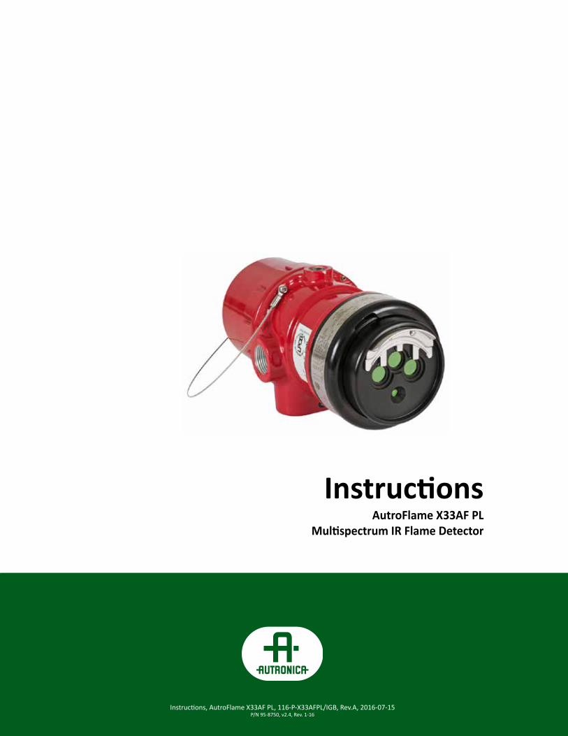
InstructionsAutroFlame X33AF PL
Multispectrum IR Flame Detector
Instructions, AutroFlame X33AF PL, 116-P-X33AFPL/IGB, 2016-07-04 P/N 95-8713 v1.1, rev. 7/14
Instructions, AutroFlame X33AF PL, 116-P-X33AFPL/IGB, 2016-07-04 P/N 95-8713 v1.1, rev. 7/14
Instructions, AutroFlame X33AF PL, 116-P-X33AFPL/IGB, Rev. A, 2016-11-04 P/N 95-8750
Instructions, AutroFlame X33AF PL, 116-P-X33AFPL/IGB, Rev.A, 2016-07-15 P/N 95-8750, v2.4, Rev. 1-16
COPYRIGHT ©This publication, or parts thereof, may not be reproduced in any form, by any method, for any purpose.
Autronica Fire and Security AS and its subsidiaries assume no responsibility for any errors that may appear in the publication, or for damages arising from the information in it. No information in this publication should be regarded as a warranty made by Autronica Fire and Security. The information in this publication may be updated without notice.
Product names mentioned in this publication may be trademarks. They are used only for identification.
Table of Contents
DESCRIPTION . . . . . . . . . . . . . . . . . . . . . . . . . . . . . .1
LED . . . . . . . . . . . . . . . . . . . . . . . . . . . . . . . . .2
Opical Integrity (oi ) . . . . . . . . . . . . . . . . . . . . .2
Automatic Alarm Test . . . . . . . . . . . . . . . . . . .2
Communication . . . . . . . . . . . . . . . . . . . . . . . .2
Data Logging . . . . . . . . . . . . . . . . . . . . . . . . .3
Integral Wiring Compartment . . . . . . . . . . . . .3
Detector Sensitivity Levels . . . . . . . . . . . . . . .3
GENERAL APPLICATION INFORMATION . . . . . . . . .3
Response Characteristics . . . . . . . . . . . . . . . .3
Important Application Considerations . . . . . . .3
IMPORTANT SAFETY NOTES . . . . . . . . . . . . . . . . . .4
INSTALLATION . . . . . . . . . . . . . . . . . . . . . . . . . . . . . .4
Detector Positioning . . . . . . . . . . . . . . . . . . . .4
Detector Orientation . . . . . . . . . . . . . . . . . . . .5
Protection Against Moisture Damage . . . . . . .5
Wiring Procedure . . . . . . . . . . . . . . . . . . . . . .5
STARTUP PROCEDURE . . . . . . . . . . . . . . . . . . . . . .7
Fire Alarm Test . . . . . . . . . . . . . . . . . . . . . . . .7
TROUBLESHOOTING . . . . . . . . . . . . . . . . . . . . . . . . .7
MAINTENANCE . . . . . . . . . . . . . . . . . . . . . . . . . . . . .8
Cleaning Procedure . . . . . . . . . . . . . . . . . . . .8
oi plate Removal and replacement . . . . . . . . .8
X33AF PL Reflector Plates . . . . . . . . . . . . . . .9
Periodic Checkout Procedure . . . . . . . . . . . . .9
Clock Battery . . . . . . . . . . . . . . . . . . . . . . . . .9
FEATURES . . . . . . . . . . . . . . . . . . . . . . . . . . . . . . . . .9
SPECIFICATIONS . . . . . . . . . . . . . . . . . . . . . . . . . . . 10
REPLACEMENT PARTS . . . . . . . . . . . . . . . . . . . . . . 11
Replacement parts . . . . . . . . . . . . . . . . . . . . 11
DEVICE REPAIR AND RETURN . . . . . . . . . . . . . . . . 11
Accessories . . . . . . . . . . . . . . . . . . . . . . . . . 12
ORDERING INFORMATION . . . . . . . . . . . . . . . . . . . 12
APPENDIX A – FM APPROVAL AND PERFORMANCE REPORT . . . . . . . . . . . . . . . . . . . . . . . . . . . . . . . . . A-1
APPENDIX B – CSA APPROVAL . . . . . . . . . . . . . . B-1
APPENDIX C – ATEX APPROVAL . . . . . . . . . . . . . C-1
APPENDIX D – IECEX APPROVAL . . . . . . . . . . . . D-1
APPENDIX E – OFFSHORE APPROVALS . . . . . . . E-1
Type Approval . . . . . . . . . . . . . . . . . . . . . . . E-1
Type Approval . . . . . . . . . . . . . . . . . . . . . . . E-1
APPENDIX F – ADDITIONAL APPROVALS . . . . . . F-1
APPENDIX G - DECLARATION OF CONFORMITY G1

Instructions, AutroFlame X33AFPL, 116-P-X33AFPL/IGB, rev . A, 2016-11-04P/N 95-8750, v2 .4, rev . 1/16
Autronica Fire and Security ASPage 1
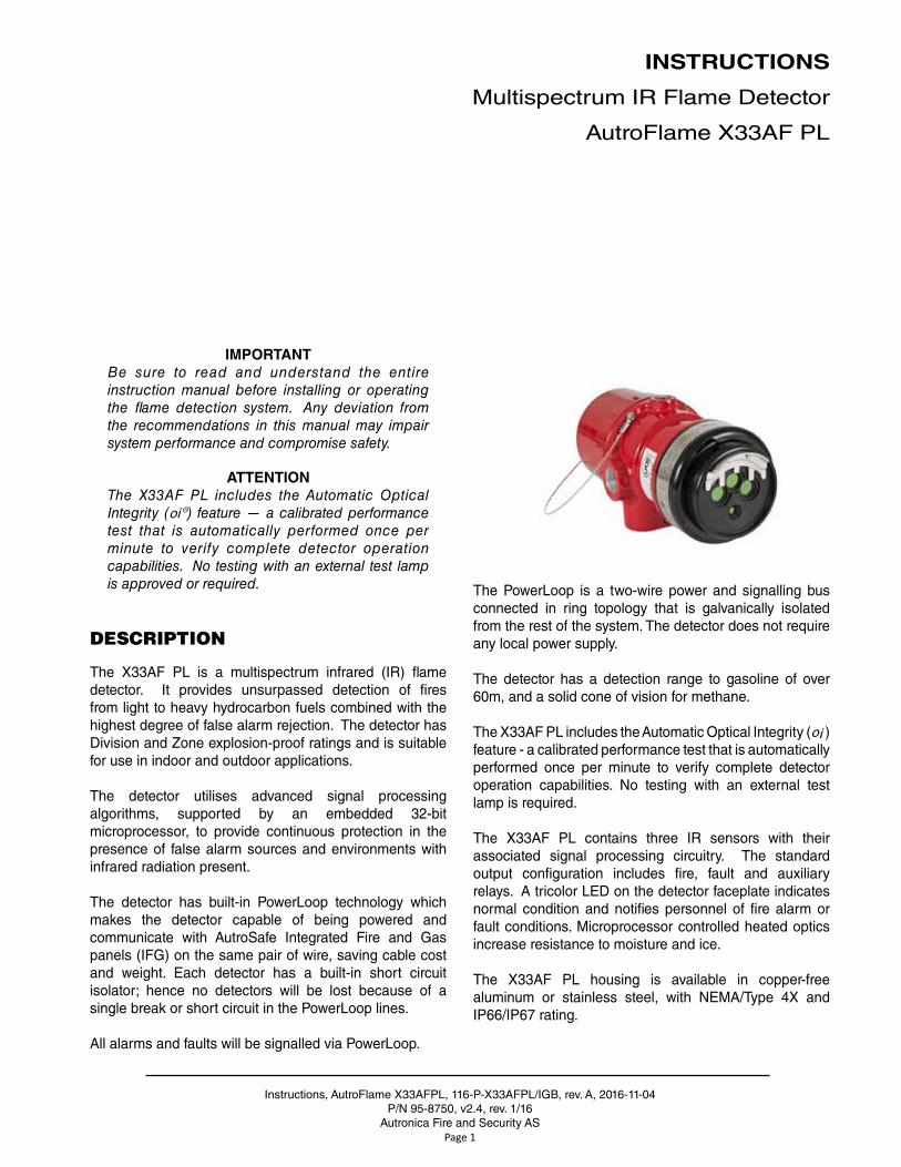
IMPORTANTBe sure to read and understand the entire instruction manual before installing or operating the flame detection system. Any deviation from the recommendations in this manual may impair system performance and compromise safety.
ATTENTIONThe X33AF PL includes the Automatic Optical Integrity (oi®) feature — a calibrated performance test that is automatically performed once per minute to verify complete detector operation capabilities. No testing with an external test lamp is approved or required.
DESCRIPTION
The X33AF PL is a multispectrum infrared (IR) flame detector . It provides unsurpassed detection of fires from light to heavy hydrocarbon fuels combined with the highest degree of false alarm rejection . The detector has Division and Zone explosion-proof ratings and is suitable for use in indoor and outdoor applications .
The detector utilises advanced signal processing algorithms, supported by an embedded 32-bit microprocessor, to provide continuous protection in the presence of false alarm sources and environments with infrared radiation present .
The detector has built-in PowerLoop technology which makes the detector capable of being powered and communicate with AutroSafe Integrated Fire and Gas panels (IFG) on the same pair of wire, saving cable cost and weight . Each detector has a built-in short circuit isolator; hence no detectors will be lost because of a single break or short circuit in the PowerLoop lines .
All alarms and faults will be signalled via PowerLoop .
The PowerLoop is a two-wire power and signalling bus connected in ring topology that is galvanically isolated from the rest of the system . The detector does not require any local power supply .
The detector has a detection range to gasoline of over 60m, and a solid cone of vision for methane .
The X33AF PL includes the Automatic Optical Integrity (oi ) feature - a calibrated performance test that is automatically performed once per minute to verify complete detector operation capabilities . No testing with an external test lamp is required .
The X33AF PL contains three IR sensors with their associated signal processing circuitry . The standard output configuration includes fire, fault and auxiliary relays . A tricolor LED on the detector faceplate indicates normal condition and notifies personnel of fire alarm or fault conditions . Microprocessor controlled heated optics increase resistance to moisture and ice .
The X33AF PL housing is available in copper-free aluminum or stainless steel, with NEMA/Type 4X and IP66/IP67 rating .
INSTRUCTIONS
Multispectrum IR Flame Detector
AutroFlame X33AF PL
Instructions, AutroFlame X33AFPL, 116-P-X33AFPL/IGB, rev . A, 2016-11-04P/N 95-8750 v2 .4, rev . 1/16
Autronica Fire and Security ASPage 2
LED
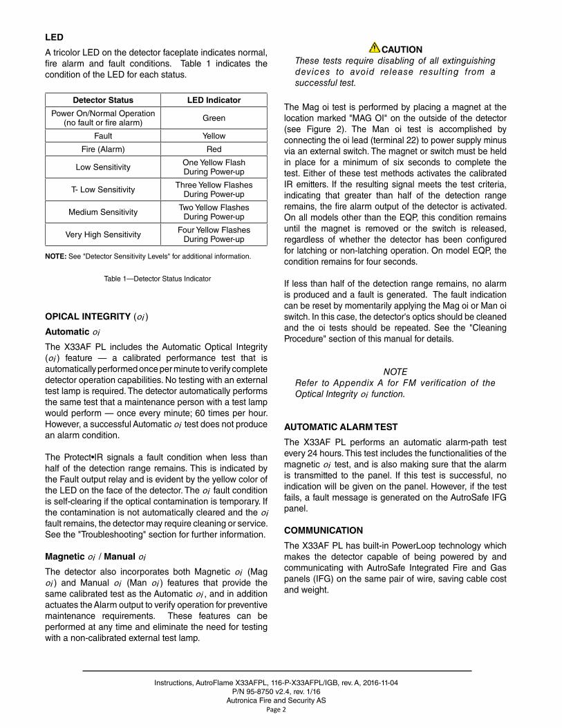
A tricolor LED on the detector faceplate indicates normal, fire alarm and fault conditions . Table 1 indicates the condition of the LED for each status .
Detector Status LED Indicator
Power On/Normal Operation(no fault or fire alarm) Green
Fault Yellow
Fire (Alarm) Red
Low Sensitivity One Yellow FlashDuring Power-up
T- Low Sensitivity Three Yellow FlashesDuring Power-up
Medium Sensitivity Two Yellow FlashesDuring Power-up
Very High Sensitivity Four Yellow FlashesDuring Power-up
NOTE: See "Detector Sensitivity Levels" for additional information .
Table 1—Detector Status Indicator
OPICAL INTEGRITY (oi )
Automatic oi
The X33AF PL includes the Automatic Optical Integrity (oi ) feature — a calibrated performance test that is automatically performed once per minute to verify complete detector operation capabilities . No testing with an external test lamp is required . The detector automatically performs the same test that a maintenance person with a test lamp would perform — once every minute; 60 times per hour . However, a successful Automatic oi test does not produce an alarm condition .
The Protect•IR signals a fault condition when less than half of the detection range remains . This is indicated by the Fault output relay and is evident by the yellow color of the LED on the face of the detector . The oi fault condition is self-clearing if the optical contamination is temporary . If the contamination is not automatically cleared and the oi fault remains, the detector may require cleaning or service . See the "Troubleshooting" section for further information .
Magnetic oi / Manual oi
The detector also incorporates both Magnetic oi (Mag oi ) and Manual oi (Man oi ) features that provide the same calibrated test as the Automatic oi , and in addition actuates the Alarm output to verify operation for preventive maintenance requirements . These features can be performed at any time and eliminate the need for testing with a non-calibrated external test lamp .
CAUTIONThese tests require disabling of all extinguishing devices to avoid release resulting from a successful test.
The Mag oi test is performed by placing a magnet at the location marked "MAG OI" on the outside of the detector (see Figure 2) . The Man oi test is accomplished by connecting the oi lead (terminal 22) to power supply minus via an external switch . The magnet or switch must be held in place for a minimum of six seconds to complete the test . Either of these test methods activates the calibrated IR emitters . If the resulting signal meets the test criteria, indicating that greater than half of the detection range remains, the fire alarm output of the detector is activated . On all models other than the EQP, this condition remains until the magnet is removed or the switch is released, regardless of whether the detector has been configured for latching or non-latching operation . On model EQP, the condition remains for four seconds .
If less than half of the detection range remains, no alarm is produced and a fault is generated . The fault indication can be reset by momentarily applying the Mag oi or Man oi switch . In this case, the detector's optics should be cleaned and the oi tests should be repeated . See the "Cleaning Procedure" section of this manual for details .
NOTERefer to Appendix A for FM verification of the Optical Integrity oi function.
AUTOMATIC ALARM TEST
The X33AF PL performs an automatic alarm-path test every 24 hours . This test includes the functionalities of the magnetic oi test, and is also making sure that the alarm is transmitted to the panel . If this test is successful, no indication will be given on the panel . However, if the test fails, a fault message is generated on the AutroSafe IFG panel .
COMMUNICATION
The X33AF PL has built-in PowerLoop technology which makes the detector capable of being powered by and communicating with AutroSafe Integrated Fire and Gas panels (IFG) on the same pair of wire, saving cable cost and weight .
Instructions, AutroFlame X33AFPL, 116-P-X33AFPL/IGB, rev . A, 2016-11-04P/N 95-8750, v2 .4, rev . 1/16
Autronica Fire and Security ASPage 3
DATA LOGGING
Data logging capability is also provided . Status conditions such as normal, power down, general and oi faults, pre-alarm, fire alarm, time and temperature are recorded . Each event is time and date stamped, along with the temperature and input voltage . Event data is stored in non-volatile memory when the event becomes active, and again when the status changes . Data from the log can only be extracted at the factory .
INTEGRAL WIRING COMPARTMENT
All external wiring to the device is connected within the integral junction box . The detector is furnished with four conduit entries, with M25 threads .
DETECTOR SENSITIVITY LEVELS
There are four factory configured sensitivity levels available for the X33AF PL Flame Detector:
Very High, Medium, Low and T-Low .
The following criteria should be considered whenchoosing a sensitivity level for the intended application:• Detector placement
• Speed of response based on fuel type and fire size (see Appendix A for response times)
• Distance between the hazard and the flame detector
Additional information on X33AF PL Flame Detector performance results and sensitivities can be found in Appendix A, the FM Approval and Performance Report .
Consult the factory with any questions on how to choose the optimum sensitivity level for the intended application .
GENERAL APPLICATION INFORMATION
RESPONSE CHARACTERISTICS
Response is dependent on the detector's sensitivity setting, distance, type of fuel, temperature of the fuel, and time required for the fire to come to equilibrium . As with all fire tests, results must be interpreted according to an individual application .
See Appendix A for third-party approved fire test results .Additional fire test results are available from Autronica .
IMPORTANT APPLICATION CONSIDERATIONS
In applying any type of sensing device as a fire detector, it is important to know of any conditions that can prevent the device from responding to fire, and also to know what other sources besides fire can cause the device to respond .
Welding
It is recommended that the system be bypassed during welding operations in situations where the possibility of a false alarm cannot be tolerated . Gas welding mandates system bypass, since the gas torch is an actual fire . Arc welding rods can contain organic binder materials in the flux that burn during the welding operation and are detectable by the X33AF PL . Welding rods with clay binders do not burn and will not be detected by the X33AF PL . However, system bypass is always recommended, since the material being welded may be contaminated with organic substances (paint, oil, etc .) that will burn and possibly cause the X33AF PL to alarm .
Due to the possibility of an alarm condition, arc welding should not be performed within 40 feet (12 .2 m) of the detector configured to very high sensitivity, within 10 feet (3 .0 m) at medium sensitivity, within 5 feet (1 .5 m) at T-Low sensitivity, or at Low sensitivity .
Artificial Lighting
The X33AF PL should not be located within 3 feet (0 .9 m) of artificial lights . Excess heating of the detector could occur due to heat radiating from the lights .
EMI/RFI Interference
The X33AF PL is resistant to interference by EMI and RFI, and is EMC Directive compliant . It will not respond to a 5 watt walkie-talkie at distances greater than 1 foot . Do not operate a walkie-talkie within 1 foot of the X33AF PL .
Non-Carbon Fires
The X33AF PL is a multiple spectrum IR device with detection limited to carbonaceous fuels . It should not be used to detect fires from fuels that do not contain carbon,
Instructions, AutroFlame X33AFPL, 116-P-X33AFPL/IGB, rev . A, 2016-11-04P/N 95-8750 v2 .4, rev . 1/16
Autronica Fire and Security ASPage 4
such as hydrogen, sulfur, and burning metals .
IMPORTANT SAFETY NOTES
WARNINGDo not open the detector assembly in a hazardous area when power is applied. The detector contains limited serviceable components and should never be opened. Doing so could disturb critical optical alignment and calibration parameters, possibly causing serious damage.
CAUTIONThe wiring procedures in this manual are intended to ensure proper functioning of the device under normal conditions. However, because of the many variations in wiring codes and regulations, total compliance to these ordinances cannot be guaranteed. Be certain that all wiring complies with the NEC as well as all local ordinances. If in doubt, consult the authority having jurisdiction before wiring the system. The PowerLoop calculator must verify all wiring calculations. Installation must be done by a properly trained person.
CAUTIONTo prevent unwanted actuation or alarm, extinguishing devices must be disabled prior to performing system tests or maintenance.
CAUTIONThe multispectrum IR flame detectors are to be installed in places where the risk of mechanical damages is low.
ATTENTIONRemove the protective cap from the front of the detector before activating the system.
ATTENTIONObserve precautions for handling electrostatic sensitive devices.
INSTALLATION
NOTEThe recommended lubricant for threads and O-rings is a silicone free grease (part number 116-005003-001) available from Autronica. Under no circumstances should a lubricant containing silicone be used.
DETECTOR POSITIONING
Detectors should be positioned to provide the best unobstructed view of the area to be protected . The following factors should also be taken into consideration:
• Identify all high risk fire ignition sources .
• Be sure that enough detectors are used to adequately cover the hazardous area .
• Be sure that the unit is easily accessible for cleaning and other periodic servicing .
• Verify that all detectors in the system are properly located and positioned so that any fire hazards are within both the Field of View (FOV) and detection range of the detector . The Q1201C Laser Aimer is recommended for establishing the detector's FOV . Refer to the "High Resolution Field of View Diagrams" section for specific information regarding detector range and FOV .
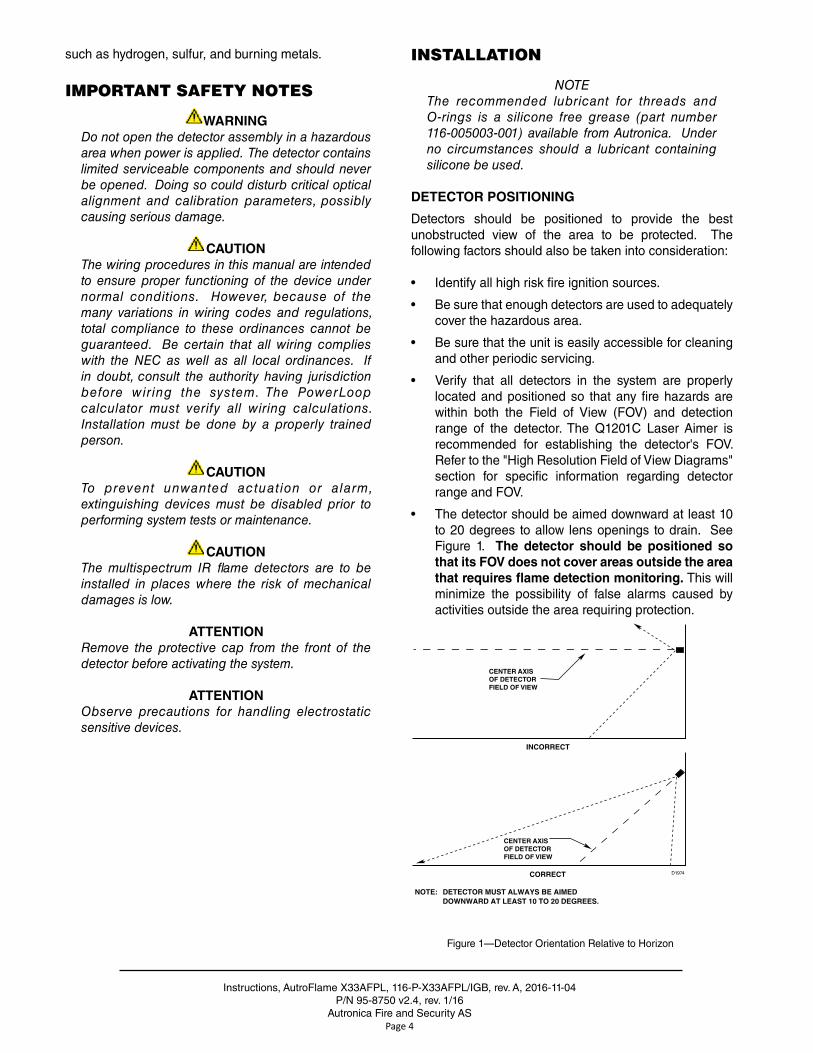
• The detector should be aimed downward at least 10 to 20 degrees to allow lens openings to drain . See Figure 1 . The detector should be positioned so that its FOV does not cover areas outside the area that requires flame detection monitoring. This will minimize the possibility of false alarms caused by activities outside the area requiring protection .
CENTER AXIS OF DETECTOR FIELD OF VIEW
CENTER AXIS OF DETECTOR FIELD OF VIEW
INCORRECT
CORRECT
NOTE: DETECTOR MUST ALWAYS BE AIMED DOWNWARD AT LEAST 10 TO 20 DEGREES.
D1974
Figure 1—Detector Orientation Relative to Horizon
Instructions, AutroFlame X33AFPL, 116-P-X33AFPL/IGB, rev . A, 2016-11-04P/N 95-8750, v2 .4, rev . 1/16
Autronica Fire and Security ASPage 5
• The detector must be mounted on a rigid surface in a low vibration area .
• Dense fog, rain or ice can absorb IR radiation and reduce the sensitivity of the detector . To ensure optimum performance, be certain that the internal optical heater is enabled on detectors that are used in applications where snow, ice, and condensation are likely to occur .
• Although IR detectors are less affected by smoke than other detectors, the X33AF PL should not be placed where rising combustion products can obscure its vision . If smoke is expected before fire, smoke or other alternative detectors should be used in conjunction with the X33AF PL . For indoor applications, if dense smoke is expected to accumulate at the onset of a fire, mount the detector on a side wall at least a few feet (approximately 1 meter) down from the ceiling .
• If possible, fire tests should be conducted to verify correct detector positioning and coverage .
• For ATEX/IECEx installations, the X33AF PL detector housing must be electrically connected to earth ground .
DETECTOR ORIENTATION
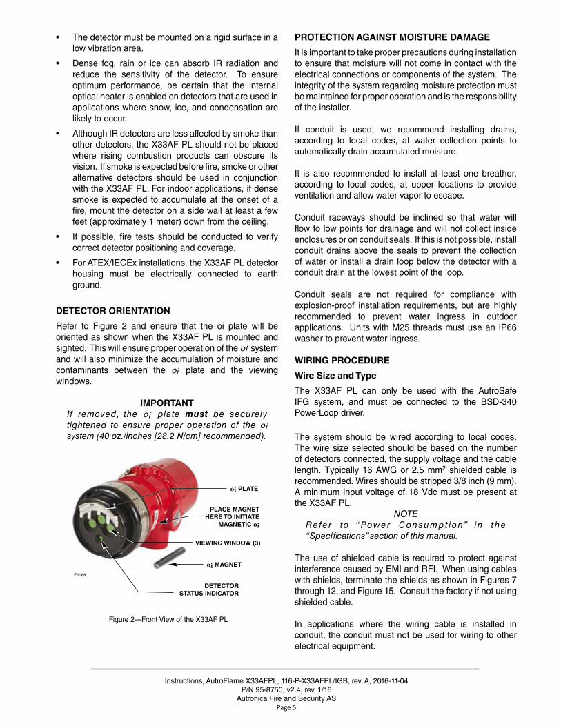
Refer to Figure 2 and ensure that the oi plate will be oriented as shown when the X33AF PL is mounted and sighted . This will ensure proper operation of the oi system and will also minimize the accumulation of moisture and contaminants between the oi plate and the viewing windows .
IMPORTANTIf removed, the oi plate must be securely tightened to ensure proper operation of the oi system (40 oz./inches [28.2 N/cm] recommended).
VIEWING WINDOW (3)
oi PLATE
PLACE MAGNETHERE TO INITIATE
MAGNETIC oi
oi MAGNET
DETECTORSTATUS INDICATOR
F2068
Figure 2—Front View of the X33AF PL
PROTECTION AGAINST MOISTURE DAMAGE
It is important to take proper precautions during installation to ensure that moisture will not come in contact with the electrical connections or components of the system . The integrity of the system regarding moisture protection must be maintained for proper operation and is the responsibility of the installer .
If conduit is used, we recommend installing drains, according to local codes, at water collection points to automatically drain accumulated moisture .
It is also recommended to install at least one breather, according to local codes, at upper locations to provide ventilation and allow water vapor to escape .
Conduit raceways should be inclined so that water will flow to low points for drainage and will not collect inside enclosures or on conduit seals . If this is not possible, install conduit drains above the seals to prevent the collection of water or install a drain loop below the detector with a conduit drain at the lowest point of the loop .
Conduit seals are not required for compliance with explosion-proof installation requirements, but are highly recommended to prevent water ingress in outdoor applications . Units with M25 threads must use an IP66 washer to prevent water ingress .
WIRING PROCEDURE
Wire Size and Type
The X33AF PL can only be used with the AutroSafe IFG system, and must be connected to the BSD-340 PowerLoop driver .
The system should be wired according to local codes . The wire size selected should be based on the number of detectors connected, the supply voltage and the cable length . Typically 16 AWG or 2 .5 mm2 shielded cable is recommended . Wires should be stripped 3/8 inch (9 mm) . A minimum input voltage of 18 Vdc must be present at the X33AF PL .
NOTERefe r to “Power Consumpt ion” i n t he “Specifications” section of this manual.
The use of shielded cable is required to protect against interference caused by EMI and RFI . When using cables with shields, terminate the shields as shown in Figures 7 through 12, and Figure 15 . Consult the factory if not using shielded cable .
In applications where the wiring cable is installed in conduit, the conduit must not be used for wiring to other electrical equipment .
Instructions, AutroFlame X33AFPL, 116-P-X33AFPL/IGB, rev . A, 2016-11-04P/N 95-8750 v2 .4, rev . 1/16
Autronica Fire and Security ASPage 6
If disconnection of power is required, separate disconnect capability must be provided .
WARNINGAll entries must contain appropriately rated plugs or fittings. It is required that each plug or fitting be wrench-tightened to an appropriate installation torque and meet the minimum thread engagement requirements per the applicable local standards, codes, and practices in order to retain the defined ratings, PTFE sealant or equivalent should be used on NPT threads.
IMPORTANTDevices certified for hazardous locations shall be installed in accordance with EN/IEC 60079-14 and NEC 505.
CAUTIONInstallation of the detector and wiring should be performed only by qualified personnel.
Detector Mounting
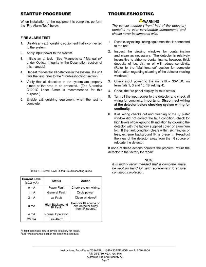
Install the mounting arm assembly on a rigid surface . The ideal installation surface should be free of vibration and suitable to receive 3/8 inch (M10) bolts with a length of at least 1 inch (25 mm) . The surface must also have sufficient capacity to hold the detector and mounting arm weights (See "Specifications" section) . Refer to the Q9033 Mounting Arm and Collar Attachment Manual (95-8686) for additional mounting information . See Figure 3 for dimensions .
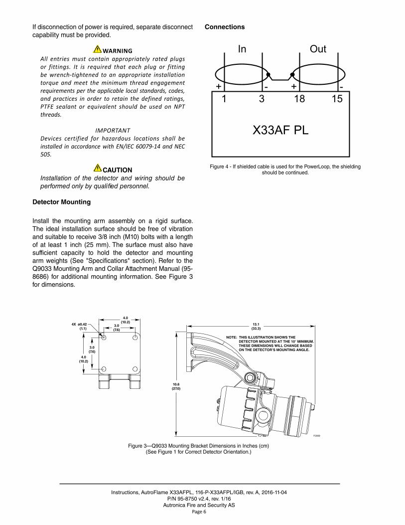
Connections
X33AF PL
1 3 18 15
In Out
+ - + -
Figure 4 - If shielded cable is used for the PowerLoop, the shieldingshould be continued .
13.1(33.3)
10.6(27.0)
4.0(10.2)
4.0(10.2)
3.0(7.6)
3.0(7.6)
4X ø0.42 (1.1)
F2069
NOTE: THIS ILLUSTRATION SHOWS THE DETECTOR MOUNTED AT THE 10° MINIMUM. THESE DIMENSIONS WILL CHANGE BASED ON THE DETECTOR’S MOUNTING ANGLE.
Figure 3—Q9033 Mounting Bracket Dimensions in Inches (cm)(See Figure 1 for Correct Detector Orientation .)
Instructions, AutroFlame X33AFPL, 116-P-X33AFPL/IGB, rev . A, 2016-11-04P/N 95-8750, v2 .4, rev . 1/16
Autronica Fire and Security ASPage 7
STARTUP PROCEDURE
When installation of the equipment is complete, perform the “Fire Alarm Test” below .
FIRE ALARM TEST
1 . Disable any extinguishing equipment that is connected to the system .
2 . Apply input power to the system .
3 . Initiate an oi test . (See “Magnetic oi / Manual oi ” under Optical Integrity in the Description section of this manual .)
4 . Repeat this test for all detectors in the system . If a unit fails the test, refer to the “Troubleshooting” section .
5 . Verify that all detectors in the system are properly aimed at the area to be protected . (The Autronica Q1201C Laser Aimer is recommended for this purpose .)
6 . Enable extinguishing equipment when the test is complete .
TROUBLESHOOTING
WARNINGThe sensor module (“front” half of the detector) contains no user serviceable components and should never be tampered with.
1 . Disable any extinguishing equipment that is connected to the unit .
2 . Inspect the viewing windows for contamination and clean as necessary . The detector is relatively insensitive to airborne contaminants, however, thick deposits of ice, dirt, or oil will reduce sensitivity . (Refer to the “Maintenance” section for complete information regarding cleaning of the detector viewing windows .)
3 . Check input power to the unit (18 – 30V DC on terminals 1, 3 and 15, 18 . ref . fig . 4) .
4 . Check the fire panel display for fault status .
5 . Turn off the input power to the detector and check all wiring for continuity . Important: Disconnect wiring at the detector before checking system wiring for continuity.
6 . If all wiring checks out and cleaning of the oi plate/window did not correct the fault condition, check for high levels of background IR radiation by covering the detector with the factory supplied cover or aluminum foil . If the fault condition clears within six minutes or less, extreme background IR is present . Re-adjust the view of the detector away from the IR source or relocate the detector .
If none of these actions corrects the problem, return the detector to the factory for repair .
NOTEIt is highly recommended that a complete spare be kept on hand for field replacement to ensure continuous protection.Table 3—Current Level Output Troubleshooting Guide
1If fault continues, return device to factory for repair .2See “Maintenance” section for cleaning procedure .
Current Level (±0.3 mA)
Status Action
0 mA Power Fault Check system wiring .
1 mA General Fault Cycle power1
2 mA oi Fault Clean windows2
3 mA High Background IR Fault
Remove IR source or aim detector away
from IR source .
4 mA Normal Operation
20 mA Fire Alarm
Instructions, AutroFlame X33AFPL, 116-P-X33AFPL/IGB, rev . A, 2016-11-04P/N 95-8750 v2 .4, rev . 1/16
Autronica Fire and Security ASPage 8
MAINTENANCE
IMPORTANTPer iod ic f lamepath inspect ions are not recommended, since the product is not intended to be serviced and provides proper ingress protection to eliminate potential deterioration of the flamepaths.
WARNINGTo avoid a potential electrostatic discharge (ESD), the painted surface of the detector should only be cleaned with a damp cloth.
WARNINGThe sensor module (“front” half of the detector) contains no user serviceable components and should never be tampered with.
To maintain maximum sensitivity and false alarm resistance, the viewing windows of the X33AF PL must be kept relatively clean . Refer to the procedure below for cleaning instructions .
CLEANING PROCEDURE
CAUTIONDisable any extinguishing equipment that is connected to the unit to prevent unwanted actuation.
To clean the windows and oi plate, use Autronicas window cleaner (part number 116-001680-001) and a soft cloth, cotton swab or tissue and refer to the following procedure .
1. Disable any extinguishing equipment that is connected to the unit.
2 . Since the X33AF PL is less affected by contamination than other detectors, removal of the oi plate is needed only under extreme conditions . In addition, it is not necessary to achieve perfect cleanliness, because IR is not significantly absorbed by slight films of oil and/or salt . If a fault condition is still indicated after cleaning, remove and clean the oi Plate Removal and Replacement procedure .
3 . In all environments, clean all three viewing windows and reflector surfaces thoroughly . Use a cotton swab and Autonicas window cleaning solution . Use Isopropyl alcohol for contaminations that Autronicas window cleaning solution can not remove .
IMPORTANTWhen used in extreme environments, the reflective surface of the detector oi plate may eventually deteriorate, resulting in reoccurring oi faults and the need for oi plate replacement.
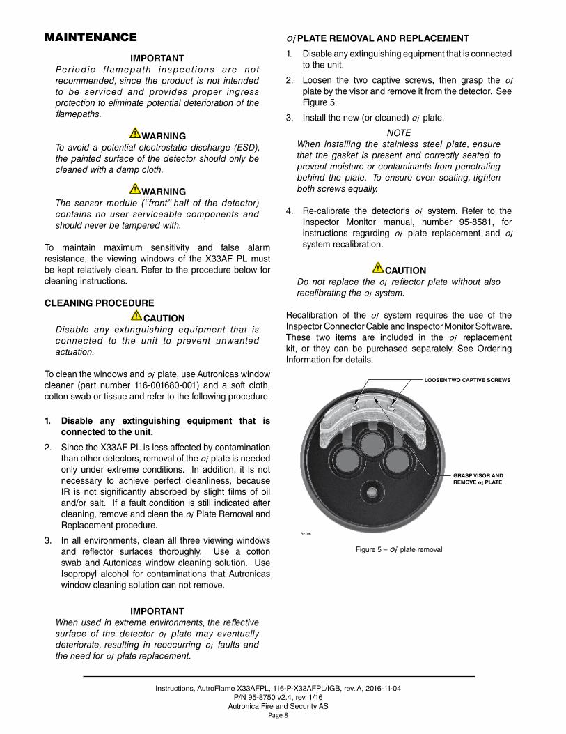
oi PLATE REMOVAL AND REPLACEMENT
1 . Disable any extinguishing equipment that is connected to the unit .
2 . Loosen the two captive screws, then grasp the oi plate by the visor and remove it from the detector . See Figure 5 .
3 . Install the new (or cleaned) oi plate .
NOTEWhen installing the stainless steel plate, ensure that the gasket is present and correctly seated to prevent moisture or contaminants from penetrating behind the plate. To ensure even seating, tighten both screws equally.
4 . Re-calibrate the detector's oi system . Refer to the Inspector Monitor manual, number 95-8581, for instructions regarding oi plate replacement and oi system recalibration .
CAUTIONDo not replace the oi reflector plate without also recalibrating the oi system.
Recalibration of the oi system requires the use of the Inspector Connector Cable and Inspector Monitor Software . These two items are included in the oi replacement kit, or they can be purchased separately . See Ordering Information for details .
LOOSEN TWO CAPTIVE SCREWS
GRASP VISOR ANDREMOVE oi PLATE
B2106
Figure 5 – oi plate removal
Instructions, AutroFlame X33AFPL, 116-P-X33AFPL/IGB, rev . A, 2016-11-04P/N 95-8750, v2 .4, rev . 1/16
Autronica Fire and Security ASPage 9
X33AF PL REFLECTOR PLATES
X33AF PL models are supplied with either a black or a stainless steel reflector plate . These plates are not interchangeable . Order the replacement that matches the reflector plate on your X33AF PL flame detector .
CLOCK BATTERY
The real time clock has a backup battery that will operate the clock with no external power for nominally 10 years . It is recommended that the battery be replaced every 7 years . Return the device to the factory for battery replacement if needed .
NOTEIf the backup battery is depleted, there is no effect on the operation of the flame detector, but the time stamping of the data log may be affected.
FEATURES
• Long detection range to carbonaceous fires .
• Unequaled false alarm rejection .
• Responds to a fire in the presence of modulated blackbody radiation (i .e . heaters, ovens, turbines) without false alarm .
• Microprocessor controlled heated optics for increased resistance to moisture and ice
• Automatic, manual or magnetic optical integrity (oi ) testing
• Automatic alarm-path test is performed once every 24 hours
• Easily replaceable oi plate .
• FDT/DMT capable
• Multiple sensitivity levels
• A tricolor LED on the detector faceplate indicates normal condition and notifies personnel of fire alarm or fault conditions
• Operates under adverse weather conditions and in dirty environments
• Mounting arm allows easy sighting
• Integral wiring compartment for ease of installation .
• Redundant PowerLoop communications and power supply
• Explosion-proof/flame-proof detector housing . Meets FM, CSA, ATEX Directive and IECEx certification requirements
• Class A wiring per NFPA-72
• Meets NFPA-33 response requirement for under 0 .5 second (available when model selected)
• 5 year warranty
• RFI and EMC Directive compliant
Instructions, AutroFlame X33AFPL, 116-P-X33AFPL/IGB, rev . A, 2016-11-04P/N 95-8750 v2 .4, rev . 1/16
Autronica Fire and Security ASPage 10
SPECIFICATIONS
OPERATING VOLTAGE— The BSD-340 PowerLoop driver provides the power . The operating voltage is 20 to 30Vdc .
POWER CONSUMPTION—Without heater: 4 watts at 24 Vdc nominal; 5 .2 watts at 24 Vdc in alarm . 4 .5 watts at 30 Vdc nominal; 6 .5 watts at 30 Vdc in alarm .Heater only: 8 watts maximum .Total power: 14 .5 watts maximum
POWER UP TIME—Fault indication clears after 0 .5 second; device is ready to indicate an alarm condition after 30 seconds .
TEMPERATURE RANGE—Operating: –40°F to +167°F (–40°C to +75°C) .Storage: –67°F to +185°F (–55°C to +85°C) .Hazardous location ratings from –55°C to +125°C .
HUMIDITY RANGE—0 to 95% relative humidity, can withstand 100% condensing humidity for short periods of time .
CONE OF VISION—The detector has a 90° cone of vision (horizontal) with the highest sensitivity lying along the central axis . Unlike conventional detectors, the X33AF PL provides full coverage at a minimum of 70% of the maximum detection distance .
Perfect cone of vision for methane fire detection — 100 feet (30 .5 m) on and off axis on “very high” setting .
Refer to Appendix A for FM Approved cone of vision data .
RESPONSE TIME—Typical response times are under 10 seconds . Models are available that can respond to automotive paint gun fires in under 0 .5 seconds . See Appendix A for actual response times .
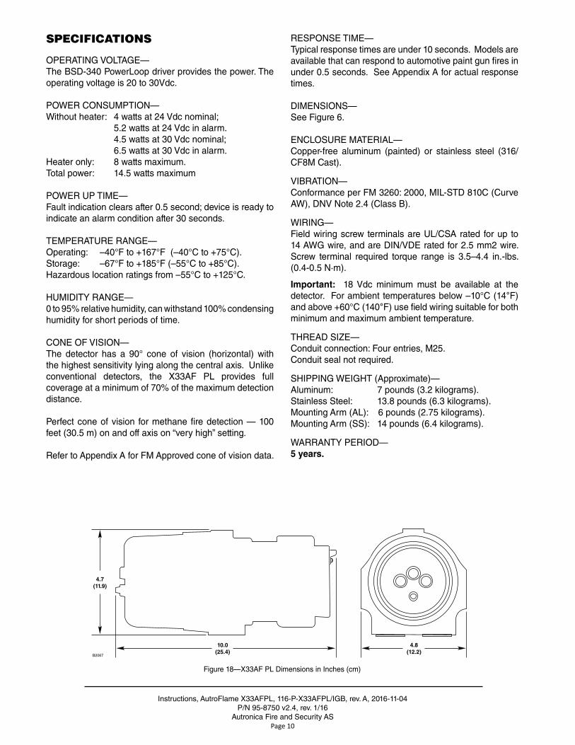
DIMENSIONS—See Figure 6 .
ENCLOSURE MATERIAL—Copper-free aluminum (painted) or stainless steel (316/CF8M Cast) .
VIBRATION—Conformance per FM 3260: 2000, MIL-STD 810C (Curve AW), DNV Note 2 .4 (Class B) .
WIRING—Field wiring screw terminals are UL/CSA rated for up to 14 AWG wire, and are DIN/VDE rated for 2 .5 mm2 wire . Screw terminal required torque range is 3 .5–4 .4 in .-lbs . (0 .4-0 .5 N·m) .
Important: 18 Vdc minimum must be available at the detector . For ambient temperatures below –10°C (14°F) and above +60°C (140°F) use field wiring suitable for both minimum and maximum ambient temperature .
THREAD SIZE—Conduit connection: Four entries, M25 .Conduit seal not required .
SHIPPING WEIGHT (Approximate)—Aluminum: 7 pounds (3 .2 kilograms) .Stainless Steel: 13 .8 pounds (6 .3 kilograms) .Mounting Arm (AL): 6 pounds (2 .75 kilograms) .Mounting Arm (SS): 14 pounds (6 .4 kilograms) .
WARRANTY PERIOD—5 years.
10.0(25.4)
4.8(12.2)
4.7(11.9)
B2067
Figure 18—X33AF PL Dimensions in Inches (cm)
Instructions, AutroFlame X33AFPL, 116-P-X33AFPL/IGB, rev . A, 2016-11-04P/N 95-8750, v2 .4, rev . 1/16
Autronica Fire and Security ASPage 11
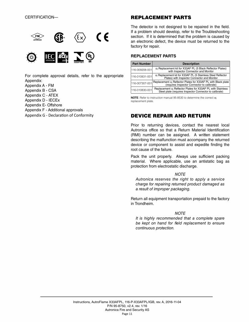
CERTIFICATION—
®
For complete approval details, refer to the appropriate Appendix:Appendix A - FMAppendix B - CSAAppendix C - ATEXAppendix D - IECExAppendix E- OffshoreAppendix F - Additional approvalsAppendix G - Declaration of Conformity
REPLACEMENT PARTS
The detector is not designed to be repaired in the field . If a problem should develop, refer to the Troubleshooting section . If it is determined that the problem is caused by an electronic defect, the device must be returned to the factory for repair .
REPLACEMENT PARTS
Part Number Description
116-009208-001 oi Replacement kit for X33AF PL (5 Black Reflector Plates) with Inspector Connector and Monitor
116-010831-001 oi Replacement kit for X33AF PL (5 Stainless Steel Reflector Plates) with Inspector Connector and Monitor
116-007307-001 Replacement oi Reflector Plates for X33AF PL with Black plate (requires Inspector Connector to calibrate)
116-010830-001 Replacement oi Reflector Plates for X33AF PL with Stainless Steel plate (requires Inspector Connector to calibrate)
NOTE: Refer to instruction manual 95-8530 to determine the correct oi replacement plate.
DEVICE REPAIR AND RETURN
Prior to returning devices, contact the nearest local Autronica office so that a Return Material Identification (RMI) number can be assigned . A written statement describing the malfunction must accompany the returned device or component to assist and expedite finding the root cause of the failure .
Pack the unit properly . Always use sufficient packing material . Where applicable, use an antistatic bag as protection from electrostatic discharge .
NOTEAutronica reserves the right to apply a service charge for repairing returned product damaged as a result of improper packaging.
Return all equipment transportation prepaid to the factory in Trondheim .
NOTE It is highly recommended that a complete spare be kept on hand for field replacement to ensure continuous protection.
Instructions, AutroFlame X33AFPL, 116-P-X33AFPL/IGB, rev . A, 2016-11-04P/N 95-8750 v2 .4, rev . 1/16
Autronica Fire and Security ASPage 12
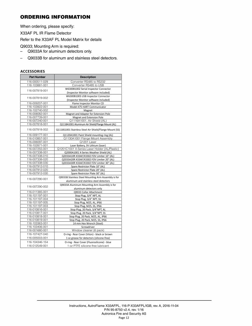
ORDERING INFORMATION
When ordering, please specify:
X33AF PL IR Flame Detector
Refer to the X33AF PL Model Matrix for details
Q9033; Mounting Arm is required: – Q9033A for aluminum detectors only .
– Q9033B for aluminum and stainless steel detectors .
ACCESSORIESPart Number Description
116-000511-029 Converter RS485 to RS232116-103881-001 Converter RS485 to USB
116-007819-001W6300B1002 Serial Inspector Connector (Inspector Monitor software included)
116-007819-002W6300B1003 USB Inspector Connector (Inspector Monitor software included)
116-009207-001 Flame Inspector Monitor CD116-103922-001 Model 475 HART Communicator116-102740-002 Magnet116-008082-001 Magnet and Adapter for Extension Pole116-007739-001 Magnet and Extension Pole116-007240-001 Q1116A1001, Air Shield (AL)116-007818-001 Q1118A1001 Aluminum Air Shield/Flange Mount (AL)
116-007818-002 Q1118S1001 Stainless Steel Air Shield/Flange Mount (SS)
116-009177-001 Q1120A1001 Paint Shield mounting ring (AL)116-010857-001 Q1130A1001 Flange Mount Assembly116-006097-001 Q1201 Laser116-102871-001 Laser Battery, 3V Lithium (laser)116-007255-001 Q1201C1001 X-Series Laser Holder (AL/Plastic)116-007338-001 Q2000A1001 X-Series Weather Shield (AL)116-007338-010 Q2033A10R X33AF/X3302 FOV Limiter 10° (AL)116-007338-020 Q2033A20R X33AF/X3302 FOV Limiter 20° (AL)116-007338-030 Q2033A30R X33AF/X3302 FOV Limiter 30° (AL)116-007912-010 Spare Restrictor Plate 10° (AL)116-007912-020 Spare Restrictor Plate 20° (AL)116-007912-030 Spare Restrictor Plate 30° (AL)
116-007290-001Q9033B Stainless Steel Mounting Arm Assembly is for
aluminum and stainless steel detectors
116-007290-002Q9033A Aluminum Mounting Arm Assembly is for
aluminum detectors only 116-011385-001 Q9033 Collar Attachment116-101197-001 Stop Plug, 3/4” NPT, AL116-101197-004 Stop Plug, 3/4” NPT, SS116-101197-005 Stop Plug, M25, AL, IP66116-101197-003 Stop Plug, M25, SS, IP66116-010816-001 Stop Plug, 20 Pack, 3/4”NPT, AL116-010817-001 Stop Plug, 20 Pack, 3/4”NPT, SS116-010818-001 Stop Plug, 20 Pack, M25, AL, IP66116-010819-001 Stop Plug, 20 Pack, M25, SS, IP66116-103363-001 14 mm Hex Wrench (Steel)116-103406-001 Screwdriver116-001680-001 Window cleaner (6 pack)116-107427-040116-005003-001
O-ring - Rear Cover (Viton) - black or brown1 oz grease for detectors (silicone-free)
116-104346-154116-012549-001
O-ring - Rear Cover (Fluorosilicone) - blue1 oz PTFE silicone-free lubricant
Instructions, AutroFlame X33AFPL, 116-P-X33AFPL/IGB, rev . A, 2016-11-04P/N 95-8750, v2 .4, rev . 1/16
Autronica Fire and Security ASPage 13
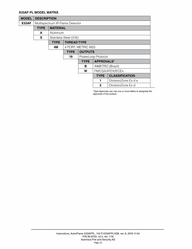
X33AF PL MODEL MATRIX
MODEL DESCRIPTION
X33AF Multispectrum IR Flame DetectorTYPE MATERIAL
A AluminumS Stainless Steel (316)
TYPE THREAD TYPE
4M 4 PORT, METRIC M25TYPE OUTPUTS
19 PowerLoop ProtocolTYPE APPROVALS*
B INMETRO (Brazil)W FM/CSA/ATEX/IECEx
TYPE CLASSIFICATION
1 Division/Zone Ex d e2 Division/Zone Ex d
*Type Approvals can use one or more letters to designate theapprovals of the product .
Instructions, AutroFlame X33AFPL, 116-P-X33AFPL/IGB, rev . A, 2016-11-04P/N 95-8750 v2 .4, rev . 1/16
Autronica Fire and Security ASPage 14
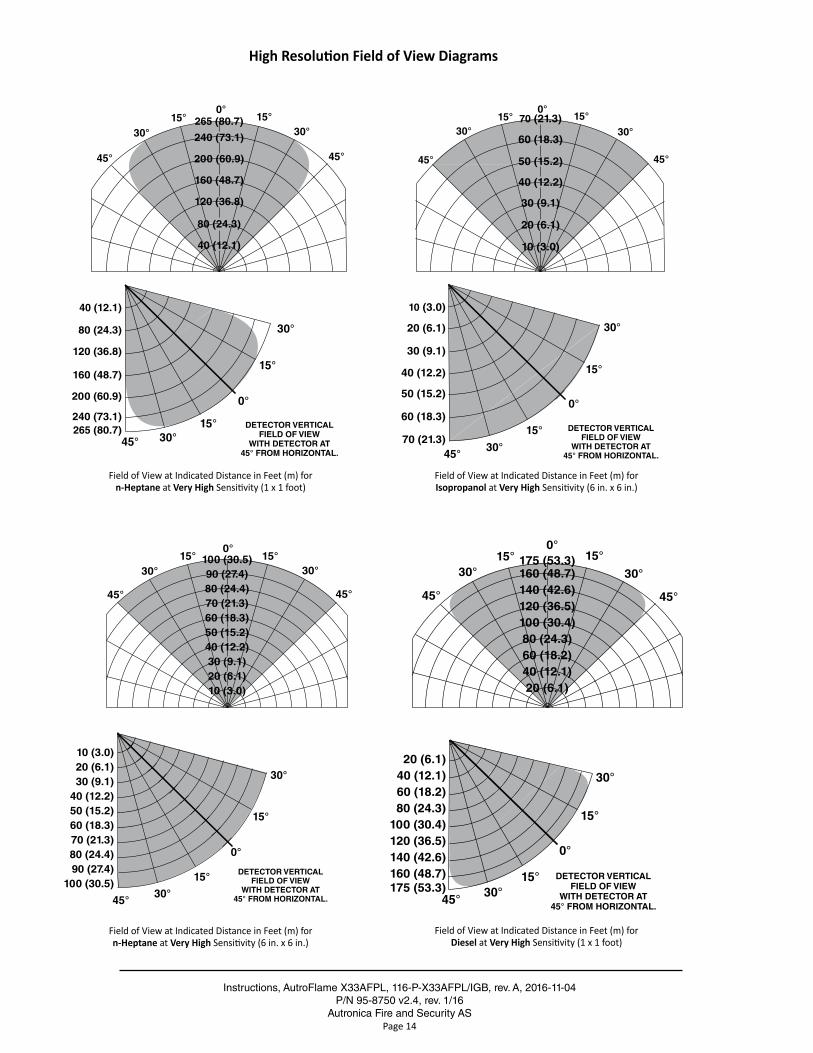
Field of View at Indicated Distance in Feet (m) for n-Heptane at Very High Sensitivity (6 in. x 6 in.)
Field of View at Indicated Distance in Feet (m) for Isopropanol at Very High Sensitivity (6 in. x 6 in.)
High Resolution Field of View Diagrams
Field of View at Indicated Distance in Feet (m) for n-Heptane at Very High Sensitivity (1 x 1 foot)
0°
15°
45°
15°
30°
30°DETECTOR VERTICAL
FIELD OF VIEWWITH DETECTOR AT
45° FROM HORIZONTAL.
0°15°15°
30°
45°
30°
45°
265 (80.7)
240 (73.1)
200 (60.9)
160 (48.7)
120 (36.8)
80 (24.3)
40 (12.1)
40 (12.1)
80 (24.3)
120 (36.8)
160 (48.7)
200 (60.9)
240 (73.1)265 (80.7)
0°
15°
45°
15°
30°
30°
DETECTOR VERTICALFIELD OF VIEW
WITH DETECTOR AT45° FROM HORIZONTAL.
0°15°15°
30°
45°
30°
45°
70 (21.3)
60 (18.3)
50 (15.2)
40 (12.2)
30 (9.1)
20 (6.1)
10 (3.0)
10 (3.0)
20 (6.1)
30 (9.1)
40 (12.2)
50 (15.2)
60 (18.3)
70 (21.3)
0°15°
30°
45°
15°30°
45°
100 (30.5)90 (27.4)80 (24.4)70 (21.3)60 (18.3)50 (15.2)40 (12.2)30 (9.1)20 (6.1)10 (3.0)
0°
15°
45°
15°
30°
30°
DETECTOR VERTICALFIELD OF VIEW
WITH DETECTOR AT45° FROM HORIZONTAL.
10 (3.0)20 (6.1)30 (9.1)
40 (12.2)50 (15.2)60 (18.3)70 (21.3)80 (24.4)90 (27.4)
100 (30.5)
0°15°
30°
45°
15°
30°
45°
175 (53.3)160 (48.7)140 (42.6)120 (36.5)100 (30.4)80 (24.3)60 (18.2)40 (12.1)20 (6.1)
20 (6.1)40 (12.1)60 (18.2)80 (24.3)
100 (30.4)120 (36.5)140 (42.6)160 (48.7)175 (53.3)
0°
15°
45°
15°
30°
30°DETECTOR VERTICAL
FIELD OF VIEWWITH DETECTOR AT
45° FROM HORIZONTAL.
Field of View at Indicated Distance in Feet (m) for Diesel at Very High Sensitivity (1 x 1 foot)
Instructions, AutroFlame X33AFPL, 116-P-X33AFPL/IGB, rev . A, 2016-11-04P/N 95-8750, v2 .4, rev . 1/16
Autronica Fire and Security ASPage 15
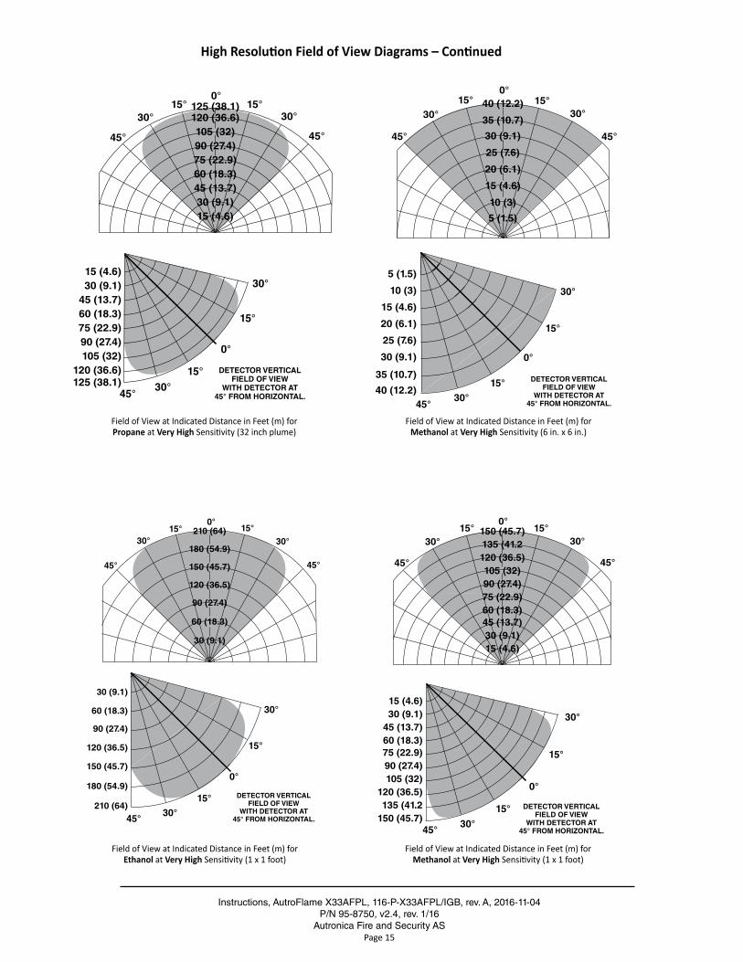
High Resolution Field of View Diagrams – Continued
Field of View at Indicated Distance in Feet (m) for Ethanol at Very High Sensitivity (1 x 1 foot)
Field of View at Indicated Distance in Feet (m) for Methanol at Very High Sensitivity (1 x 1 foot)
0°15°
30°
45°
15°30°
45°
125 (38.1)120 (36.6)105 (32)90 (27.4)75 (22.9)60 (18.3)45 (13.7)30 (9.1)15 (4.6)
15 (4.6)30 (9.1)
45 (13.7)60 (18.3)75 (22.9)90 (27.4)105 (32)
120 (36.6)125 (38.1)
0°
15°
45°
15°
30°
30°
DETECTOR VERTICALFIELD OF VIEW
WITH DETECTOR AT45° FROM HORIZONTAL.
Field of View at Indicated Distance in Feet (m) for Propane at Very High Sensitivity (32 inch plume)
0°15°
30°
45°
15°30°
45°
0°
15°
45°
15°
30°
30°
DETECTOR VERTICALFIELD OF VIEW
WITH DETECTOR AT45° FROM HORIZONTAL.
40 (12.2)
35 (10.7)
30 (9.1)
25 (7.6)
20 (6.1)
15 (4.6)
10 (3)
5 (1.5)
5 (1.5)
10 (3)
15 (4.6)
20 (6.1)
25 (7.6)
30 (9.1)
35 (10.7)
40 (12.2)
Field of View at Indicated Distance in Feet (m) for Methanol at Very High Sensitivity (6 in. x 6 in.)
0°
15°
45°
15°
30°
30°
DETECTOR VERTICALFIELD OF VIEW
WITH DETECTOR AT45° FROM HORIZONTAL.
0°15°15°
30°
45°
30°
45°
210 (64)
180 (54.9)
150 (45.7)
120 (36.5)
90 (27.4)
60 (18.3)
30 (9.1)
30 (9.1)
60 (18.3)
90 (27.4)
120 (36.5)
150 (45.7)
180 (54.9)
210 (64)
0°15°
30°
45°
15°30°
45°
150 (45.7)135 (41.2120 (36.5)105 (32)90 (27.4)75 (22.9)60 (18.3)45 (13.7)30 (9.1)15 (4.6)
15 (4.6)30 (9.1)
45 (13.7)60 (18.3)75 (22.9)90 (27.4)105 (32)
120 (36.5)135 (41.2
150 (45.7)
0°
15°
45°
15°
30°
30°
DETECTOR VERTICALFIELD OF VIEW
WITH DETECTOR AT45° FROM HORIZONTAL.
Instructions, AutroFlame X33AFPL, 116-P-X33AFPL/IGB, rev . A, 2016-11-04P/N 95-8750 v2 .4, rev . 1/16
Autronica Fire and Security ASPage 16
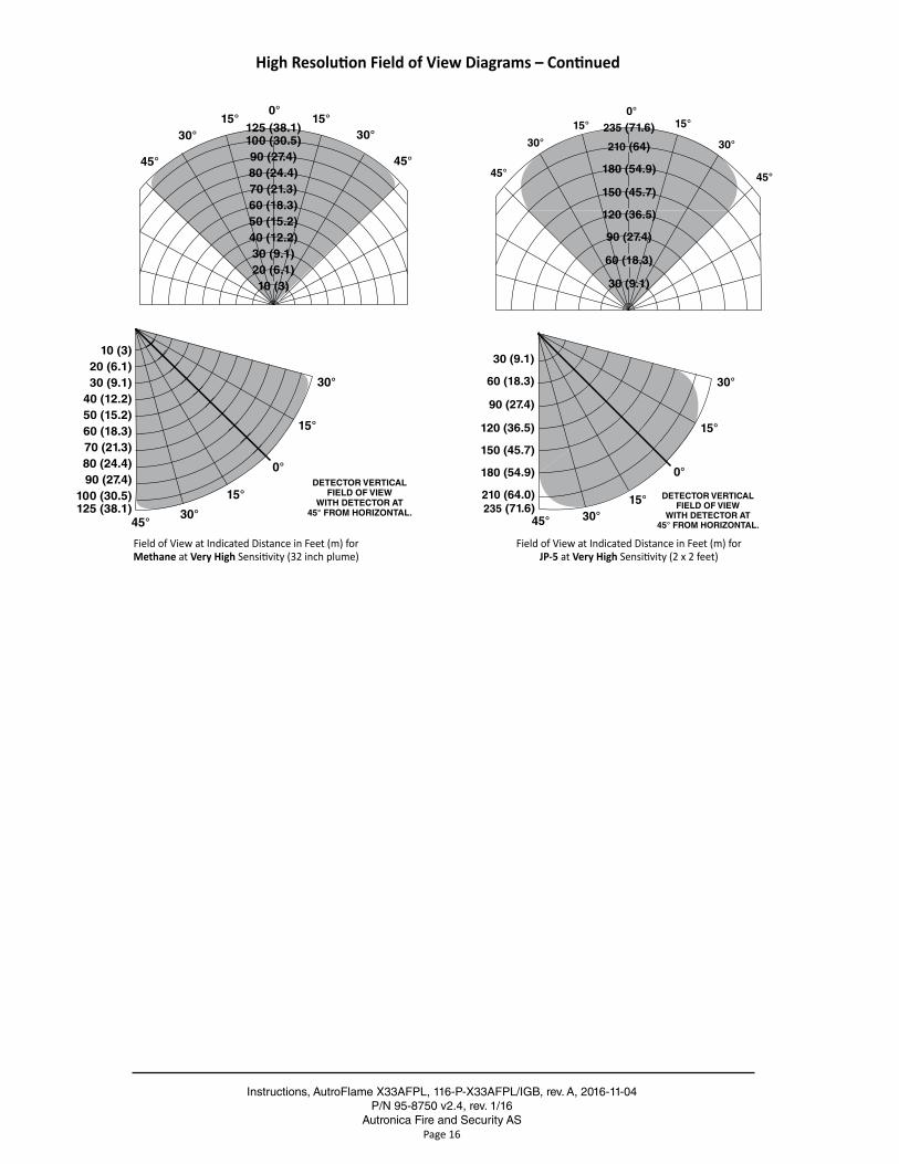
High Resolution Field of View Diagrams – Continued
0°15°
30°
45°
15°30°
45°
125 (38.1)100 (30.5)90 (27.4)80 (24.4)70 (21.3)60 (18.3)50 (15.2)40 (12.2)30 (9.1)20 (6.1)10 (3)
0°
15°
45°
15°
30°
30°
DETECTOR VERTICALFIELD OF VIEW
WITH DETECTOR AT45° FROM HORIZONTAL.
10 (3)20 (6.1)30 (9.1)
40 (12.2)50 (15.2)60 (18.3)70 (21.3)80 (24.4)90 (27.4)
100 (30.5)125 (38.1)
Field of View at Indicated Distance in Feet (m) for Methane at Very High Sensitivity (32 inch plume)
Field of View at Indicated Distance in Feet (m) for JP-5 at Very High Sensitivity (2 x 2 feet)
0°15°15°
30°
45°
30°
45°
235 (71.6)
210 (64)
180 (54.9)
150 (45.7)
120 (36.5)
90 (27.4)
60 (18.3)
30 (9.1)
30 (9.1)
60 (18.3)
90 (27.4)
120 (36.5)
150 (45.7)
180 (54.9)
210 (64.0)235 (71.6)
0°
15°
45°
15°
30°
30°
DETECTOR VERTICALFIELD OF VIEW
WITH DETECTOR AT45° FROM HORIZONTAL.
Instructions, AutroFlame X33AFPL, 116-P-X33AFPL/IGB, rev . A, 2016-11-04P/N 95-8750, v2 .4, rev . 1/16
Autronica Fire and Security ASPage 17
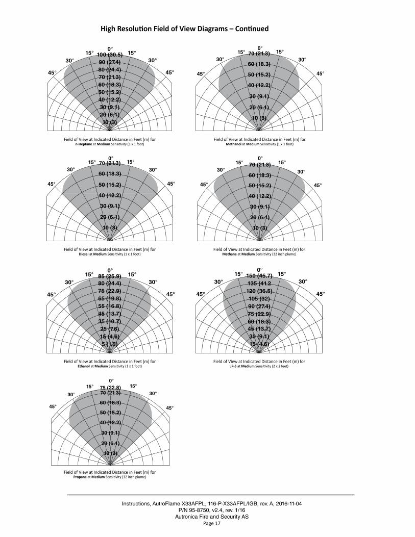
High Resolution Field of View Diagrams – Continued
Field of View at Indicated Distance in Feet (m) for n-Heptane at Medium Sensitivity (1 x 1 foot)
Field of View at Indicated Distance in Feet (m) for Diesel at Medium Sensitivity (1 x 1 foot)
Field of View at Indicated Distance in Feet (m) for Methane at Medium Sensitivity (32 inch plume)
Field of View at Indicated Distance in Feet (m) for Ethanol at Medium Sensitivity (1 x 1 foot)
Field of View at Indicated Distance in Feet (m) for JP-5 at Medium Sensitivity (2 x 2 feet)
Field of View at Indicated Distance in Feet (m) for Propane at Medium Sensitivity (32 inch plume)
0°15°
30°
45°
15°30°
45°
100 (30.5)90 (27.4)80 (24.4)70 (21.3)60 (18.3)50 (15.2)40 (12.2)30 (9.1)20 (6.1)10 (3)
0°15°15°
30°
45°
30°
45°
70 (21.3)
60 (18.3)
50 (15.2)
40 (12.2)
30 (9.1)
20 (6.1)
10 (3)
Field of View at Indicated Distance in Feet (m) for Methanol at Medium Sensitivity (1 x 1 foot)
0°15°15°
30°
45°
30°
45°
70 (21.3)
60 (18.3)
50 (15.2)
40 (12.2)
30 (9.1)
20 (6.1)
10 (3)
0°15°15°
30°
45°
30°
45°
70 (21.3)
60 (18.3)
50 (15.2)
40 (12.2)
30 (9.1)
20 (6.1)
10 (3)
0°15°
30°
45°
15°30°
45°
85 (25.9)80 (24.4)75 (22.9)65 (19.8)55 (16.8)45 (13.7)35 (10.7)25 (7.6)15 (4.6)5 (1.5)
0°15°
30°
45°
15°30°
45°
150 (45.7)135 (41.2120 (36.5)105 (32)90 (27.4)75 (22.9)60 (18.3)45 (13.7)30 (9.1)15 (4.6)
0°15°15°
30°
45°
30°
45°
75 (22.8)70 (21.3)
60 (18.3)
50 (15.2)
40 (12.2)
30 (9.1)
20 (6.1)
10 (3)
Instructions, AutroFlame X33AFPL, 116-P-X33AFPL/IGB, rev . A, 2016-11-04P/N 95-8750, v2 .4, rev . 1/16
Autronica Fire and Security ASPage A-1
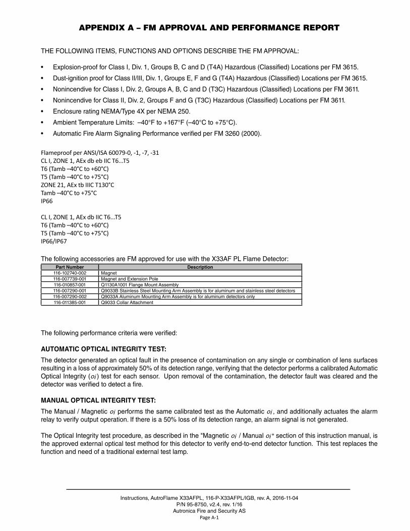
APPENDIX A – FM APPROVAL AND PERFORMANCE REPORT
THE FOLLOWING ITEMS, FUNCTIONS AND OPTIONS DESCRIBE THE FM APPROVAL:
• Explosion-proof for Class I, Div . 1, Groups B, C and D (T4A) Hazardous (Classified) Locations per FM 3615 .
• Dust-ignition proof for Class II/III, Div . 1, Groups E, F and G (T4A) Hazardous (Classified) Locations per FM 3615 .
• Nonincendive for Class I, Div . 2, Groups A, B, C and D (T3C) Hazardous (Classified) Locations per FM 3611 .
• Nonincendive for Class II, Div . 2, Groups F and G (T3C) Hazardous (Classified) Locations per FM 3611 .
• Enclosure rating NEMA/Type 4X per NEMA 250 .
• Ambient Temperature Limits: –40°F to +167°F (–40°C to +75°C) .
• Automatic Fire Alarm Signaling Performance verified per FM 3260 (2000) .
Flameproof per ANSI/ISA 60079-0, -1, -7, -31CL I, ZONE 1, AEx db eb IIC T6...T5T6 (Tamb –40°C to +60°C)T5 (Tamb –40°C to +75°C)ZONE 21, AEx tb IIIC T130°CTamb –40°C to +75°CIP66
CL I, ZONE 1, AEx db IIC T6...T5T6 (Tamb –40°C to +60°C)T5 (Tamb –40°C to +75°C)IP66/IP67
The following accessories are FM approved for use with the X33AF PL Flame Detector:Part Number Description
116-102740-002 Magnet116-007739-001 Magnet and Extension Pole116-010857-001 Q1130A1001 Flange Mount Assembly116-007290-001 Q9033B Stainless Steel Mounting Arm Assembly is for aluminum and stainless steel detectors116-007290-002 Q9033A Aluminum Mounting Arm Assembly is for aluminum detectors only116-011385-001 Q9033 Collar Attachment
The following performance criteria were verified:
AUTOMATIC OPTICAL INTEGRITY TEST:
The detector generated an optical fault in the presence of contamination on any single or combination of lens surfaces resulting in a loss of approximately 50% of its detection range, verifying that the detector performs a calibrated Automatic Optical Integrity (oi ) test for each sensor . Upon removal of the contamination, the detector fault was cleared and the detector was verified to detect a fire .
MANUAL OPTICAL INTEGRITY TEST:
The Manual / Magnetic oi performs the same calibrated test as the Automatic oi , and additionally actuates the alarm relay to verify output operation . If there is a 50% loss of its detection range, an alarm signal is not generated .
The Optical Integrity test procedure, as described in the "Magnetic oi / Manual oi " section of this instruction manual, is the approved external optical test method for this detector to verify end-to-end detector function . This test replaces the function and need of a traditional external test lamp .
Instructions, AutroFlame X33AFPL, 116-P-X33AFPL/IGB, rev . A, 2016-11-04P/N 95-8750 v2 .4, rev . 1/16
Autronica Fire and Security ASPage A-2
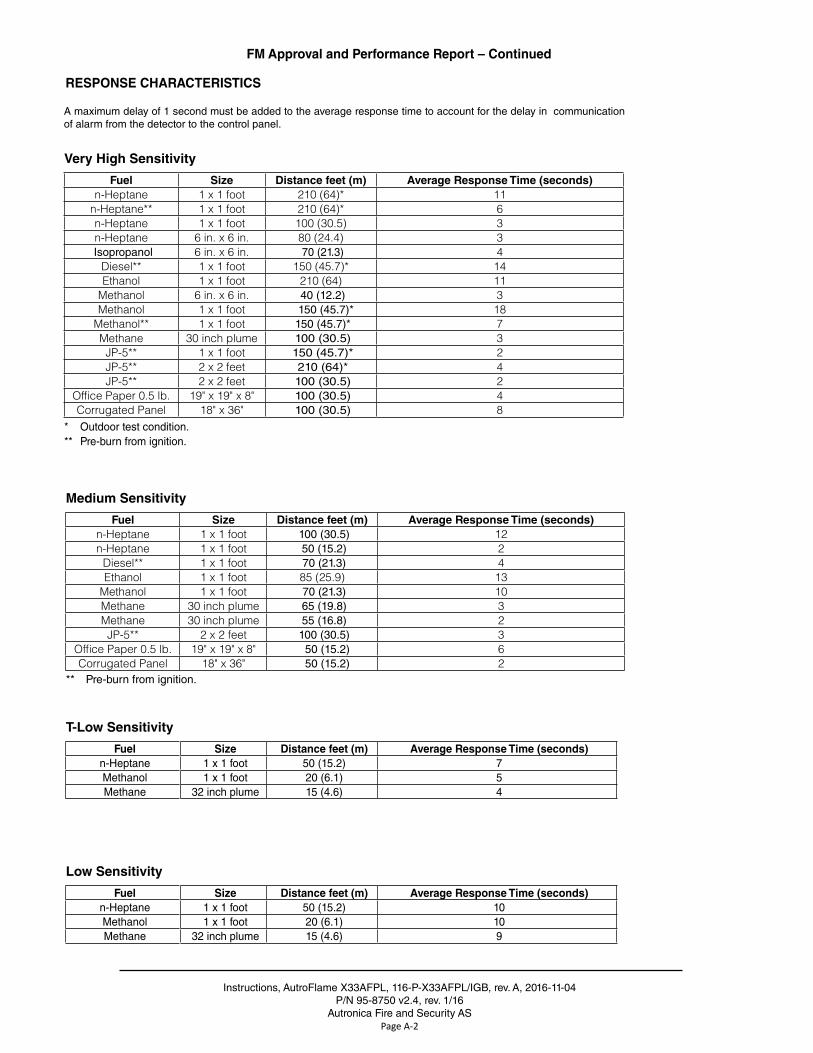
FM Approval and Performance Report – Continued
Very High Sensitivity
Fuel Size Distance feet (m) Average Response Time (seconds)n-Heptane 1 x 1 foot 210 (64)* 11
n-Heptane** 1 x 1 foot 210 (64)* 6n-Heptane 1 x 1 foot 100 (30.5) 3n-Heptane 6 in. x 6 in. 80 (24.4) 3Isopropanol 6 in. x 6 in. 70 (21 .3) 4
Diesel** 1 x 1 foot 150 (45.7)* 14Ethanol 1 x 1 foot 210 (64) 11
Methanol 6 in. x 6 in. 40 (12 .2) 3Methanol 1 x 1 foot 150 (45 .7)* 18
Methanol** 1 x 1 foot 150 (45 .7)* 7Methane 30 inch plume 100 (30 .5) 3
JP-5** 1 x 1 foot 150 (45 .7)* 2JP-5** 2 x 2 feet 210 (64)* 4JP-5** 2 x 2 feet 100 (30 .5) 2
Office Paper 0.5 lb. 19" x 19" x 8" 100 (30 .5) 4Corrugated Panel 18" x 36" 100 (30 .5) 8
* Outdoor test condition .** Pre-burn from ignition .
Medium Sensitivity
Fuel Size Distance feet (m) Average Response Time (seconds)n-Heptane 1 x 1 foot 100 (30 .5) 12n-Heptane 1 x 1 foot 50 (15 .2) 2
Diesel** 1 x 1 foot 70 (21 .3) 4Ethanol 1 x 1 foot 85 (25.9) 13
Methanol 1 x 1 foot 70 (21 .3) 10Methane 30 inch plume 65 (19 .8) 3Methane 30 inch plume 55 (16 .8) 2
JP-5** 2 x 2 feet 100 (30 .5) 3Office Paper 0.5 lb. 19" x 19" x 8" 50 (15 .2) 6Corrugated Panel 18" x 36" 50 (15 .2) 2
** Pre-burn from ignition .
Low Sensitivity
Fuel Size Distance feet (m) Average Response Time (seconds)n-Heptane 1 x 1 foot 50 (15 .2) 10Methanol 1 x 1 foot 20 (6 .1) 10Methane 32 inch plume 15 (4 .6) 9
T-Low Sensitivity
Fuel Size Distance feet (m) Average Response Time (seconds)n-Heptane 1 x 1 foot 50 (15 .2) 7Methanol 1 x 1 foot 20 (6 .1) 5Methane 32 inch plume 15 (4 .6) 4
RESPONSE CHARACTERISTICS
A maximum delay of 1 second must be added to the average response time to account for the delay in communication of alarm from the detector to the control panel .
Instructions, AutroFlame X33AFPL, 116-P-X33AFPL/IGB, rev . A, 2016-11-04P/N 95-8750, v2 .4, rev . 1/16
Autronica Fire and Security ASPage A-3
FM Approval and Performance Report – Continued
Very High Sensitivity
False Alarm SourceDistancefeet (m)
Fire SourceDistancefeet (m)
Average Response Time(seconds)
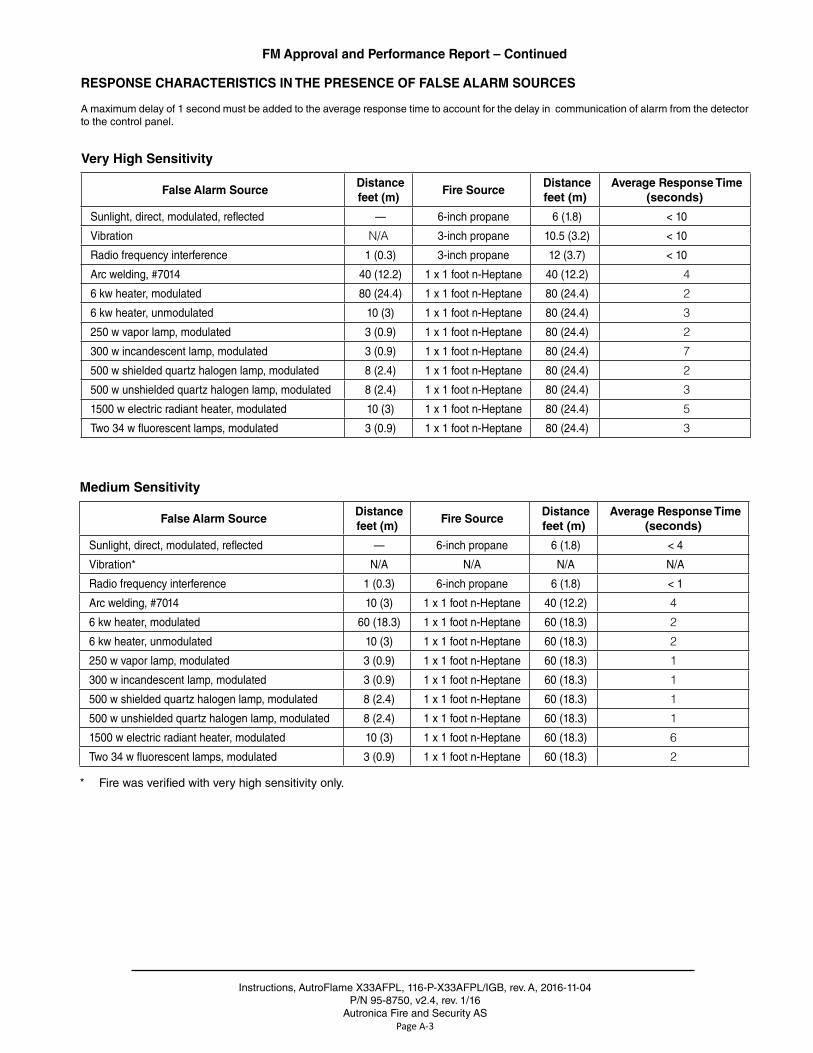
Sunlight, direct, modulated, reflected — 6-inch propane 6 (1 .8) < 10
Vibration N/A 3-inch propane 10 .5 (3 .2) < 10
Radio frequency interference 1 (0 .3) 3-inch propane 12 (3 .7) < 10
Arc welding, #7014 40 (12 .2) 1 x 1 foot n-Heptane 40 (12 .2) 4
6 kw heater, modulated 80 (24 .4) 1 x 1 foot n-Heptane 80 (24 .4) 2
6 kw heater, unmodulated 10 (3) 1 x 1 foot n-Heptane 80 (24 .4) 3
250 w vapor lamp, modulated 3 (0 .9) 1 x 1 foot n-Heptane 80 (24 .4) 2
300 w incandescent lamp, modulated 3 (0 .9) 1 x 1 foot n-Heptane 80 (24 .4) 7
500 w shielded quartz halogen lamp, modulated 8 (2 .4) 1 x 1 foot n-Heptane 80 (24 .4) 2
500 w unshielded quartz halogen lamp, modulated 8 (2 .4) 1 x 1 foot n-Heptane 80 (24 .4) 3
1500 w electric radiant heater, modulated 10 (3) 1 x 1 foot n-Heptane 80 (24 .4) 5
Two 34 w fluorescent lamps, modulated 3 (0 .9) 1 x 1 foot n-Heptane 80 (24 .4) 3
Medium Sensitivity
False Alarm SourceDistancefeet (m)
Fire SourceDistancefeet (m)
Average Response Time(seconds)
Sunlight, direct, modulated, reflected — 6-inch propane 6 (1 .8) < 4
Vibration* N/A N/A N/A N/A
Radio frequency interference 1 (0 .3) 6-inch propane 6 (1 .8) < 1
Arc welding, #7014 10 (3) 1 x 1 foot n-Heptane 40 (12 .2) 4
6 kw heater, modulated 60 (18 .3) 1 x 1 foot n-Heptane 60 (18 .3) 2
6 kw heater, unmodulated 10 (3) 1 x 1 foot n-Heptane 60 (18 .3) 2
250 w vapor lamp, modulated 3 (0 .9) 1 x 1 foot n-Heptane 60 (18 .3) 1
300 w incandescent lamp, modulated 3 (0 .9) 1 x 1 foot n-Heptane 60 (18 .3) 1
500 w shielded quartz halogen lamp, modulated 8 (2 .4) 1 x 1 foot n-Heptane 60 (18 .3) 1
500 w unshielded quartz halogen lamp, modulated 8 (2 .4) 1 x 1 foot n-Heptane 60 (18 .3) 1
1500 w electric radiant heater, modulated 10 (3) 1 x 1 foot n-Heptane 60 (18 .3) 6
Two 34 w fluorescent lamps, modulated 3 (0 .9) 1 x 1 foot n-Heptane 60 (18 .3) 2
* Fire was verified with very high sensitivity only .
A maximum delay of 1 second must be added to the average response time to account for the delay in communication of alarm from the detector to the control panel .
RESPONSE CHARACTERISTICS IN THE PRESENCE OF FALSE ALARM SOURCES
Instructions, AutroFlame X33AFPL, 116-P-X33AFPL/IGB, rev . A, 2016-11-04P/N 95-8750 v2 .4, rev . 1/16
Autronica Fire and Security ASPage A-4
FM Approval and Performance Report – Continued
Low Sensitivity
False Alarm SourceDistancefeet (m)
Fire SourceDistancefeet (m)
Average Response Time(seconds)
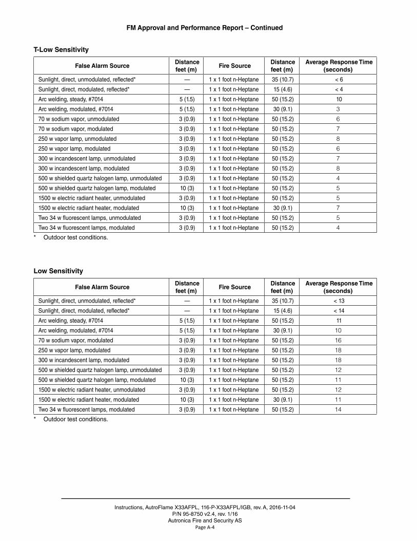
Sunlight, direct, unmodulated, reflected* — 1 x 1 foot n-Heptane 35 (10 .7) < 13
Sunlight, direct, modulated, reflected* — 1 x 1 foot n-Heptane 15 (4 .6) < 14
Arc welding, steady, #7014 5 (1 .5) 1 x 1 foot n-Heptane 50 (15 .2) 11
Arc welding, modulated, #7014 5 (1 .5) 1 x 1 foot n-Heptane 30 (9 .1) 10
70 w sodium vapor, modulated 3 (0 .9) 1 x 1 foot n-Heptane 50 (15 .2) 16
250 w vapor lamp, modulated 3 (0 .9) 1 x 1 foot n-Heptane 50 (15 .2) 18
300 w incandescent lamp, modulated 3 (0 .9) 1 x 1 foot n-Heptane 50 (15 .2) 18
500 w shielded quartz halogen lamp, unmodulated 3 (0 .9) 1 x 1 foot n-Heptane 50 (15 .2) 12
500 w shielded quartz halogen lamp, modulated 10 (3) 1 x 1 foot n-Heptane 50 (15 .2) 11
1500 w electric radiant heater, unmodulated 3 (0 .9) 1 x 1 foot n-Heptane 50 (15 .2) 12
1500 w electric radiant heater, modulated 10 (3) 1 x 1 foot n-Heptane 30 (9 .1) 11
Two 34 w fluorescent lamps, modulated 3 (0 .9) 1 x 1 foot n-Heptane 50 (15 .2) 14
* Outdoor test conditions .
T-Low Sensitivity
False Alarm SourceDistancefeet (m)
Fire SourceDistancefeet (m)
Average Response Time(seconds)
Sunlight, direct, unmodulated, reflected* — 1 x 1 foot n-Heptane 35 (10 .7) < 6
Sunlight, direct, modulated, reflected* — 1 x 1 foot n-Heptane 15 (4 .6) < 4
Arc welding, steady, #7014 5 (1 .5) 1 x 1 foot n-Heptane 50 (15 .2) 10
Arc welding, modulated, #7014 5 (1 .5) 1 x 1 foot n-Heptane 30 (9 .1) 3
70 w sodium vapor, unmodulated 3 (0 .9) 1 x 1 foot n-Heptane 50 (15 .2) 6
70 w sodium vapor, modulated 3 (0 .9) 1 x 1 foot n-Heptane 50 (15 .2) 7
250 w vapor lamp, unmodulated 3 (0 .9) 1 x 1 foot n-Heptane 50 (15 .2) 8
250 w vapor lamp, modulated 3 (0 .9) 1 x 1 foot n-Heptane 50 (15 .2) 6
300 w incandescent lamp, unmodulated 3 (0 .9) 1 x 1 foot n-Heptane 50 (15 .2) 7
300 w incandescent lamp, modulated 3 (0 .9) 1 x 1 foot n-Heptane 50 (15 .2) 8
500 w shielded quartz halogen lamp, unmodulated 3 (0 .9) 1 x 1 foot n-Heptane 50 (15 .2) 4
500 w shielded quartz halogen lamp, modulated 10 (3) 1 x 1 foot n-Heptane 50 (15 .2) 5
1500 w electric radiant heater, unmodulated 3 (0 .9) 1 x 1 foot n-Heptane 50 (15 .2) 5
1500 w electric radiant heater, modulated 10 (3) 1 x 1 foot n-Heptane 30 (9 .1) 7
Two 34 w fluorescent lamps, unmodulated 3 (0 .9) 1 x 1 foot n-Heptane 50 (15 .2) 5
Two 34 w fluorescent lamps, modulated 3 (0 .9) 1 x 1 foot n-Heptane 50 (15 .2) 4
* Outdoor test conditions .
Instructions, AutroFlame X33AFPL, 116-P-X33AFPL/IGB, rev . A, 2016-11-04P/N 95-8750, v2 .4, rev . 1/16
Autronica Fire and Security ASPage A-5
FM Approval and Performance Report – Continued
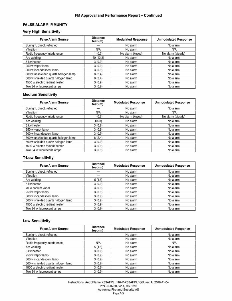
FALSE ALARM IMMUNITY
Very High Sensitivity
False Alarm Source Distancefeet (m) Modulated Response Unmodulated Response
Sunlight, direct, reflected — No alarm No alarmVibration N/A No alarm N/ARadio frequency interference 1 (0 .3) No alarm (keyed) No alarm (steady)Arc welding 40 (12 .2) No alarm No alarm6 kw heater 3 (0 .9) No alarm No alarm250 w vapor lamp 3 (0 .9) No alarm No alarm300 w incandescent lamp 3 (0 .9) No alarm No alarm500 w unshielded quartz halogen lamp 8 (2 .4) No alarm No alarm500 w shielded quartz halogen lamp 8 (2 .4) No alarm No alarm1500 w electric radiant heater 3 (0 .9) No alarm No alarmTwo 34 w fluorescent lamps 3 (0 .9) No alarm No alarm
Medium Sensitivity
False Alarm Source Distancefeet (m) Modulated Response Unmodulated Response
Sunlight, direct, reflected — No alarm No alarmVibration N/A No alarm N/ARadio frequency interference 1 (0 .3) No alarm (keyed) No alarm (steady)Arc welding 10 (3) No alarm No alarm6 kw heater 3 (0 .9) No alarm No alarm250 w vapor lamp 3 (0 .9) No alarm No alarm300 w incandescent lamp 3 (0 .9) No alarm No alarm500 w unshielded quartz halogen lamp 8 (2 .4) No alarm No alarm500 w shielded quartz halogen lamp 3 (0 .9) No alarm No alarm1500 w electric radiant heater 3 (0 .9) No alarm No alarmTwo 34 w fluorescent lamps 3 (0 .9) No alarm No alarm
T-Low Sensitivity
False Alarm Source Distancefeet (m) Modulated Response Unmodulated Response
Sunlight, direct, reflected — No alarm No alarmVibration — No alarm No alarmArc welding 5 (1 .5) No alarm No alarm6 kw heater 3 (0 .9) No alarm No alarm70 w sodium vapor 3 (0 .9) No alarm No alarm250 w vapor lamp 3 (0 .9) No alarm No alarm300 w incandescent lamp 3 (0 .9) No alarm No alarm500 w shielded quartz halogen lamp 3 (0 .9) No alarm No alarm1500 w electric radiant heater 3 (0 .9) No alarm No alarmTwo 34 w fluorescent lamps 3 (0 .9) No alarm No alarm
Low Sensitivity
False Alarm Source Distancefeet (m) Modulated Response Unmodulated Response
Sunlight, direct, reflected — No alarm No alarmVibration — No alarm No alarmRadio frequency interference N/A No alarm N/AArc welding 5 (1 .5) No alarm No alarm6 kw heater 3 (0 .9) No alarm No alarm250 w vapor lamp 3 (0 .9) No alarm No alarm300 w incandescent lamp 3 (0 .9) No alarm No alarm500 w shielded quartz halogen lamp 3 (0 .9) No alarm No alarm1500 w electric radiant heater 3 (0 .9) No alarm No alarmTwo 34 w fluorescent lamps 3 (0 .9) No alarm No alarm
Instructions, AutroFlame X33AFPL, 116-P-X33AFPL/IGB, rev . A, 2016-11-04P/N 95-8750 v2 .4, rev . 1/16
Autronica Fire and Security ASPage A-6
FM Approval and Performance Report – Continued
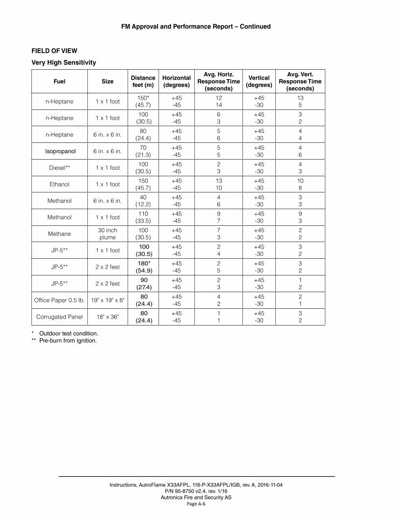
FIELD OF VIEW
Very High Sensitivity
Fuel SizeDistance feet (m)
Horizontal (degrees)
Avg. Horiz. Response Time
(seconds)
Vertical (degrees)
Avg. Vert. Response Time
(seconds)
n-Heptane 1 x 1 foot 150* (45.7)
+45-45
1214
+45-30
135
n-Heptane 1 x 1 foot 100 (30.5)
+45-45
63
+45-30
32
n-Heptane 6 in. x 6 in. 80(24.4)
+45-45
56
+45-30
44
Isopropanol 6 in. x 6 in. 70(21.3)
+45-45
55
+45-30
46
Diesel** 1 x 1 foot 100(30.5)
+45-45
23
+45-30
43
Ethanol 1 x 1 foot 150(45.7)
+45-45
1310
+45-30
108
Methanol 6 in. x 6 in. 40(12.2)
+45-45
46
+45-30
33
Methanol 1 x 1 foot 110(33.5)
+45-45
97
+45-30
93
Methane 30 inch plume
100(30.5)
+45-45
73
+45-30
22
JP-5** 1 x 1 foot 100 (30 .5)
+45-45
24
+45-30
32
JP-5** 2 x 2 feet 180* (54 .9)
+45-45
25
+45-30
32
JP-5** 2 x 2 feet 90 (27 .4)
+45-45
23
+45-30
12
Office Paper 0.5 lb. 19" x 19" x 8" 80 (24 .4)
+45-45
42
+45-30
21
Corrugated Panel 18" x 36" 80 (24 .4)
+45-45
11
+45-30
32
* Outdoor test condition .** Pre-burn from ignition .
Instructions, AutroFlame X33AFPL, 116-P-X33AFPL/IGB, rev . A, 2016-11-04P/N 95-8750, v2 .4, rev . 1/16
Autronica Fire and Security ASPage A-7
FM Approval and Performance Report – Continued
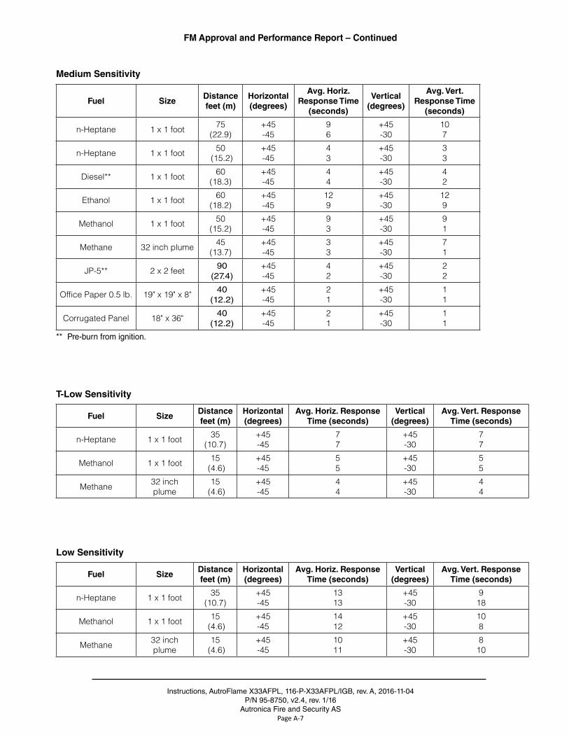
Medium Sensitivity
Fuel SizeDistance feet (m)
Horizontal (degrees)
Avg. Horiz. Response Time
(seconds)
Vertical (degrees)
Avg. Vert. Response Time
(seconds)
n-Heptane 1 x 1 foot 75(22.9)
+45-45
96
+45-30
107
n-Heptane 1 x 1 foot 50 (15.2)
+45-45
43
+45-30
33
Diesel** 1 x 1 foot 60(18.3)
+45-45
44
+45-30
42
Ethanol 1 x 1 foot 60(18.2)
+45-45
129
+45-30
129
Methanol 1 x 1 foot 50(15.2)
+45-45
93
+45-30
91
Methane 32 inch plume 45(13.7)
+45-45
33
+45-30
71
JP-5** 2 x 2 feet 90 (27 .4)
+45-45
42
+45-30
22
Office Paper 0.5 lb. 19" x 19" x 8" 40 (12 .2)
+45-45
21
+45-30
11
Corrugated Panel 18" x 36" 40 (12 .2)
+45-45
21
+45-30
11
** Pre-burn from ignition .
T-Low Sensitivity
Fuel SizeDistance feet (m)
Horizontal (degrees)
Avg. Horiz. Response Time (seconds)
Vertical (degrees)
Avg. Vert. Response Time (seconds)
n-Heptane 1 x 1 foot 35(10.7)
+45-45
77
+45-30
77
Methanol 1 x 1 foot 15 (4.6)
+45-45
55
+45-30
55
Methane 32 inch plume
15 (4.6)
+45-45
44
+45-30
44
Low Sensitivity
Fuel SizeDistance feet (m)
Horizontal (degrees)
Avg. Horiz. Response Time (seconds)
Vertical (degrees)
Avg. Vert. Response Time (seconds)
n-Heptane 1 x 1 foot 35(10.7)
+45-45
1313
+45-30
918
Methanol 1 x 1 foot 15 (4.6)
+45-45
1412
+45-30
108
Methane 32 inch plume
15 (4.6)
+45-45
1011
+45-30
810
Instructions, AutroFlame X33AFPL, 116-P-X33AFPL/IGB, rev . A, 2016-11-04P/N 95-8750, v2 .4, rev . 1/16
Autronica Fire and Security ASPage B-1
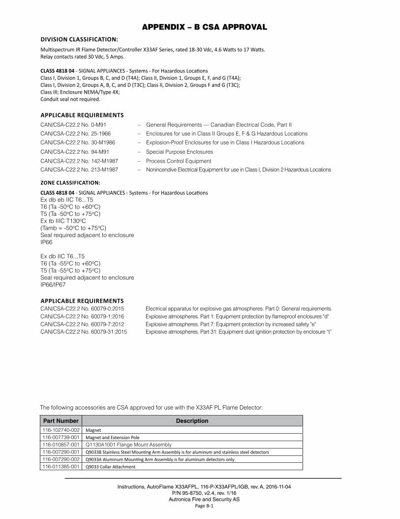
APPENDIX – B CSA APPROVALDIVISION CLASSIFICATION:Multispectrum IR Flame Detector/Controller X33AF Series, rated 18-30 Vdc, 4.6 Watts to 17 Watts.Relay contacts rated 30 Vdc, 5 Amps.
CLASS 4818 04 - SIGNAL APPLIANCES - Systems - For Hazardous LocationsClass I, Division 1, Groups B, C, and D (T4A); Class II, Division 1, Groups E, F, and G (T4A);Class I, Division 2, Groups A, B, C, and D (T3C); Class II, Division 2, Groups F and G (T3C);Class III; Enclosure NEMA/Type 4X;Conduit seal not required.
APPLICABLE REQUIREMENTSCAN/CSA-C22.2 No. 0-M91 – General Requirements — Canadian Electrical Code, Part II
CAN/CSA-C22.2 No. 25-1966 – Enclosures for use in Class II Groups E, F & G Hazardous Locations
CAN/CSA-C22.2 No. 30-M1986 – Explosion-Proof Enclosures for use in Class I Hazardous Locations
CAN/CSA-C22.2 No. 94-M91 – Special Purpose Enclosures
CAN/CSA-C22.2 No. 142-M1987 – Process Control Equipment
CAN/CSA-C22.2 No. 213-M1987 – Nonincendive Electrical Equipment for use in Class I, Division 2 Hazardous Locations
ZONE CLASSIFICATION:
CLASS 4818 04 - SIGNAL APPLIANCES - Systems - For Hazardous LocationsEx db eb IIC T6...T5T6 (Ta -50oC to +60oC)T5 (Ta -50oC to +75oC)Ex tb IIIC T130oC(Tamb = -50oC to +75oC)Seal required adjacent to enclosureIP66
Ex db IIC T6...T5T6 (Ta -55oC to +60oC)T5 (Ta -55oC to +75oC)Seal required adjacent to enclosureIP66/IP67
APPLICABLE REQUIREMENTSCAN/CSA-C22.2 No. 60079-0:2015 Electrical apparatus for explosive gas atmospheres. Part 0: General requirementsCAN/CSA-C22.2 No. 60079-1:2016 Explosive atmospheres. Part 1: Equipment protection by flameproof enclosures "d"CAN/CSA-C22.2 No. 60079-7:2012 Explosive atmospheres. Part 7: Equipment protection by increased safety "e"CAN/CSA-C22.2 No. 60079-31:2015 Explosive atmospheres. Part 31: Equipment dust ignition protection by enclosure “t”
The following accessories are CSA approved for use with the X33AF PL Flame Detector:
Part Number Description
116-102740-002 Magnet116-007739-001 Magnet and Extension Pole116-010857-001 Q1130A1001 Flange Mount Assembly116-007290-001 Q9033B Stainless Steel Mounting Arm Assembly is for aluminum and stainless steel detectors116-007290-002 Q9033A Aluminum Mounting Arm Assembly is for aluminum detectors only 116-011385-001 Q9033 Collar Attachment
Instructions, AutroFlame X33AFPL, 116-P-X33AFPL/IGB, rev . A, 2016-11-04P/N 95-8750, v2 .4, rev . 1/16
Autronica Fire and Security ASPage C-1
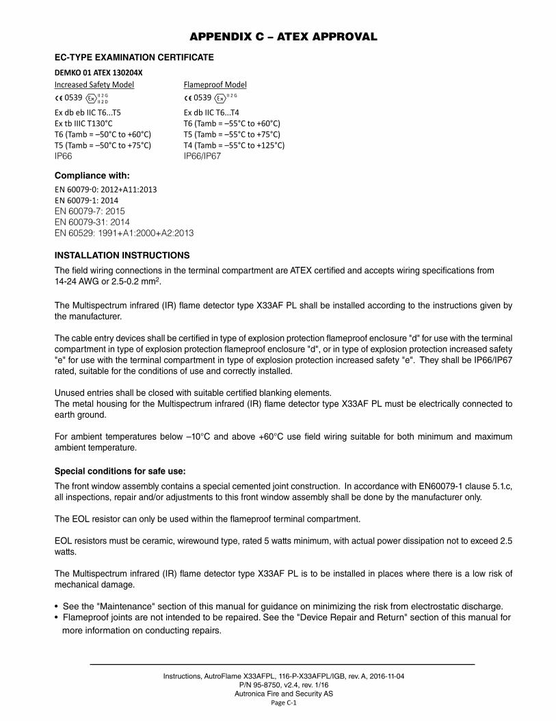
APPENDIX C – ATEX APPROVAL
EC-TYPE EXAMINATION CERTIFICATE
DEMKO 01 ATEX 130204XIncreased Safety Model Flameproof Model
0539 II 2 GII 2 D 0539
II 2 G Ex db eb IIC T6...T5 Ex db IIC T6...T4Ex tb IIIC T130°C T6 (Tamb = –55°C to +60°C)T6 (Tamb = –50°C to +60°C) T5 (Tamb = –55°C to +75°C) T5 (Tamb = –50°C to +75°C) T4 (Tamb = –55°C to +125°C)IP66 IP66/IP67
Compliance with:
EN 60079-0: 2012+A11:2013 EN 60079-1: 2014EN 60079-7: 2015 EN 60079-31: 2014EN 60529: 1991+A1:2000+A2:2013
INSTALLATION INSTRUCTIONS
The field wiring connections in the terminal compartment are ATEX certified and accepts wiring specifications from14-24 AWG or 2 .5-0 .2 mm2 .
The Multispectrum infrared (IR) flame detector type X33AF PL shall be installed according to the instructions given by the manufacturer .
The cable entry devices shall be certified in type of explosion protection flameproof enclosure "d" for use with the terminal compartment in type of explosion protection flameproof enclosure "d", or in type of explosion protection increased safety "e" for use with the terminal compartment in type of explosion protection increased safety "e" . They shall be IP66/IP67 rated, suitable for the conditions of use and correctly installed .
Unused entries shall be closed with suitable certified blanking elements .The metal housing for the Multispectrum infrared (IR) flame detector type X33AF PL must be electrically connected to earth ground .
For ambient temperatures below –10°C and above +60°C use field wiring suitable for both minimum and maximum ambient temperature .
Special conditions for safe use:
The front window assembly contains a special cemented joint construction . In accordance with EN60079-1 clause 5 .1 .c, all inspections, repair and/or adjustments to this front window assembly shall be done by the manufacturer only .
The EOL resistor can only be used within the flameproof terminal compartment .
EOL resistors must be ceramic, wirewound type, rated 5 watts minimum, with actual power dissipation not to exceed 2 .5 watts .
The Multispectrum infrared (IR) flame detector type X33AF PL is to be installed in places where there is a low risk of mechanical damage .
• See the "Maintenance" section of this manual for guidance on minimizing the risk from electrostatic discharge .• Flameproof joints are not intended to be repaired . See the "Device Repair and Return" section of this manual for more information on conducting repairs .
Instructions, AutroFlame X33AFPL, 116-P-X33AFPL/IGB, rev . A, 2016-11-04P/N 95-8750 v2 .4, rev . 1/16
Autronica Fire and Security ASPage C-2
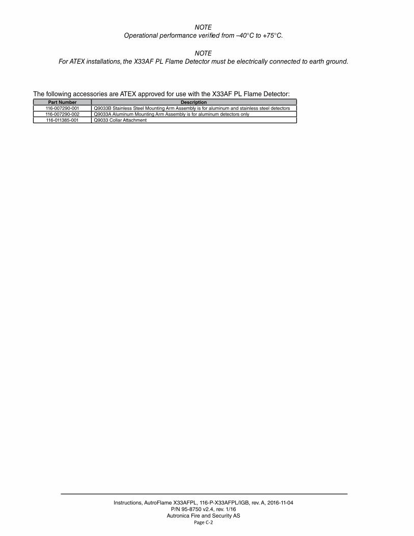
NOTEOperational performance verified from –40°C to +75°C.
NOTEFor ATEX installations, the X33AF PL Flame Detector must be electrically connected to earth ground.
The following accessories are ATEX approved for use with the X33AF PL Flame Detector:Part Number Description
116-007290-001 Q9033B Stainless Steel Mounting Arm Assembly is for aluminum and stainless steel detectors116-007290-002 Q9033A Aluminum Mounting Arm Assembly is for aluminum detectors only116-011385-001 Q9033 Collar Attachment
Instructions, AutroFlame X33AFPL, 116-P-X33AFPL/IGB, rev . A, 2016-11-04P/N 95-8750, v2 .4, rev . 1/16
Autronica Fire and Security ASPage D-1
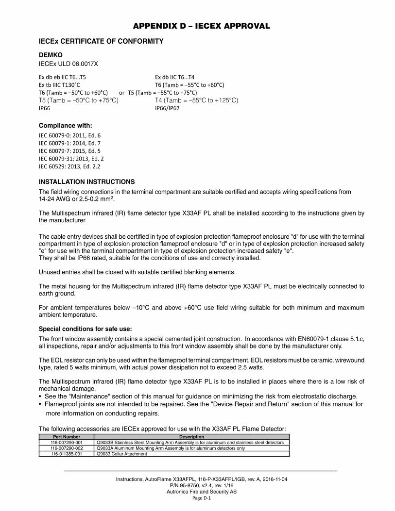
APPENDIX D – IECEX APPROVAL
IECEx CERTIFICATE OF CONFORMITY
DEMKOIECEx ULD 06 .0017X
Ex db eb IIC T6...T5 Ex db IIC T6...T4Ex tb IIIC T130°C T6 (Tamb = –55°C to +60°C)T6 (Tamb = –50°C to +60°C) or T5 (Tamb = –55°C to +75°C)T5 (Tamb = –50°C to +75°C) T4 (Tamb = –55°C to +125°C)IP66 IP66/IP67
Compliance with:
IEC 60079-0: 2011, Ed. 6 IEC 60079-1: 2014, Ed. 7IEC 60079-7: 2015, Ed. 5 IEC 60079-31: 2013, Ed. 2IEC 60529: 2013, Ed. 2.2
INSTALLATION INSTRUCTIONS
The field wiring connections in the terminal compartment are suitable certified and accepts wiring specifications from14-24 AWG or 2 .5-0 .2 mm2 .
The Multispectrum infrared (IR) flame detector type X33AF PL shall be installed according to the instructions given by the manufacturer .
The cable entry devices shall be certified in type of explosion protection flameproof enclosure "d" for use with the terminal compartment in type of explosion protection flameproof enclosure "d" or in type of explosion protection increased safety "e" for use with the terminal compartment in type of explosion protection increased safety "e" . They shall be IP66 rated, suitable for the conditions of use and correctly installed .
Unused entries shall be closed with suitable certified blanking elements .
The metal housing for the Multispectrum infrared (IR) flame detector type X33AF PL must be electrically connected to earth ground .
For ambient temperatures below –10°C and above +60°C use field wiring suitable for both minimum and maximum ambient temperature .
Special conditions for safe use:
The front window assembly contains a special cemented joint construction . In accordance with EN60079-1 clause 5 .1 .c, all inspections, repair and/or adjustments to this front window assembly shall be done by the manufacturer only .
The EOL resistor can only be used within the flameproof terminal compartment . EOL resistors must be ceramic, wirewound type, rated 5 watts minimum, with actual power dissipation not to exceed 2 .5 watts .
The Multispectrum infrared (IR) flame detector type X33AF PL is to be installed in places where there is a low risk of mechanical damage .• See the "Maintenance" section of this manual for guidance on minimizing the risk from electrostatic discharge .• Flameproof joints are not intended to be repaired . See the "Device Repair and Return" section of this manual for more information on conducting repairs .
The following accessories are IECEx approved for use with the X33AF PL Flame Detector:Part Number Description
116-007290-001 Q9033B Stainless Steel Mounting Arm Assembly is for aluminum and stainless steel detectors116-007290-002 Q9033A Aluminum Mounting Arm Assembly is for aluminum detectors only116-011385-001 Q9033 Collar Attachment
Instructions, AutroFlame X33AFPL, 116-P-X33AFPL/IGB, rev . A, 2016-11-04P/N 95-8750, v2 .4, rev . 1/16
Autronica Fire and Security ASPage F-1
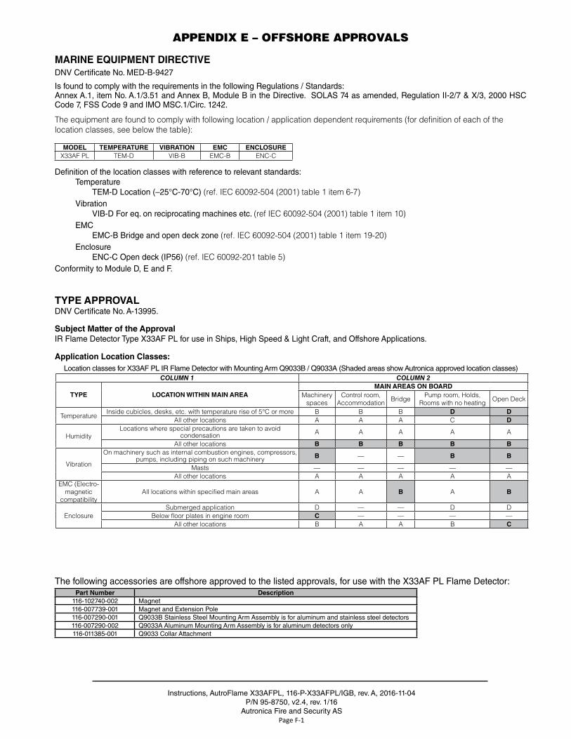
APPENDIX E – OFFSHORE APPROVALS
MARINE EQUIPMENT DIRECTIVEDNV Certificate No . MED-B-9427
Is found to comply with the requirements in the following Regulations / Standards:Annex A .1, item No . A .1/3 .51 and Annex B, Module B in the Directive . SOLAS 74 as amended, Regulation II-2/7 & X/3, 2000 HSC Code 7, FSS Code 9 and IMO MSC .1/Circ . 1242 .
The equipment are found to comply with following location / application dependent requirements (for definition of each of the location classes, see below the table):
MODEL TEMPERATURE VIBRATION EMC ENCLOSUREX33AF PL TEM-D VIB-B EMC-B ENC-C
Definition of the location classes with reference to relevant standards: Temperature TEM-D Location (–25°C-70°C) (ref. IEC 60092-504 (2001) table 1 item 6-7)
Vibration VIB-D For eq . on reciprocating machines etc . (ref IEC 60092-504 (2001) table 1 item 10)
EMC EMC-B Bridge and open deck zone (ref. IEC 60092-504 (2001) table 1 item 19-20)
Enclosure ENC-C Open deck (IP56) (ref. IEC 60092-201 table 5)Conformity to Module D, E and F .
TYPE APPROVALDNV Certificate No . A-13995 .
Subject Matter of the ApprovalIR Flame Detector Type X33AF PL for use in Ships, High Speed & Light Craft, and Offshore Applications .
Application Location Classes:
The following accessories are offshore approved to the listed approvals, for use with the X33AF PL Flame Detector:Part Number Description
116-102740-002 Magnet116-007739-001 Magnet and Extension Pole116-007290-001 Q9033B Stainless Steel Mounting Arm Assembly is for aluminum and stainless steel detectors116-007290-002 Q9033A Aluminum Mounting Arm Assembly is for aluminum detectors only116-011385-001 Q9033 Collar Attachment
Location classes for X33AF PL IR Flame Detector with Mounting Arm Q9033B / Q9033A (Shaded areas show Autronica approved location classes)COLUMN 1 COLUMN 2
TYPE LOCATION WITHIN MAIN AREAMAIN AREAS ON BOARD
Machinery spaces
Control room, Accommodation Bridge Pump room, Holds,
Rooms with no heating Open Deck
TemperatureInside cubicles, desks, etc. with temperature rise of 5°C or more B B B D D
All other locations A A A C D
HumidityLocations where special precautions are taken to avoid
condensation A A A A A
All other locations B B B B B
Vibration
On machinery such as internal combustion engines, compressors, pumps, including piping on such machinery B — — B B
Masts — — — — —All other locations A A A A A
EMC (Electro-magnetic
compatibilityAll locations within specified main areas A A B A B
EnclosureSubmerged application D — — D D
Below floor plates in engine room C — — — —All other locations B A A B C
Instructions, AutroFlame X33AFPL, 116-P-X33AFPL/IGB, rev . A, 2016-11-04P/N 95-8750, v2 .4, rev . 1/16
Autronica Fire and Security ASPage G-1
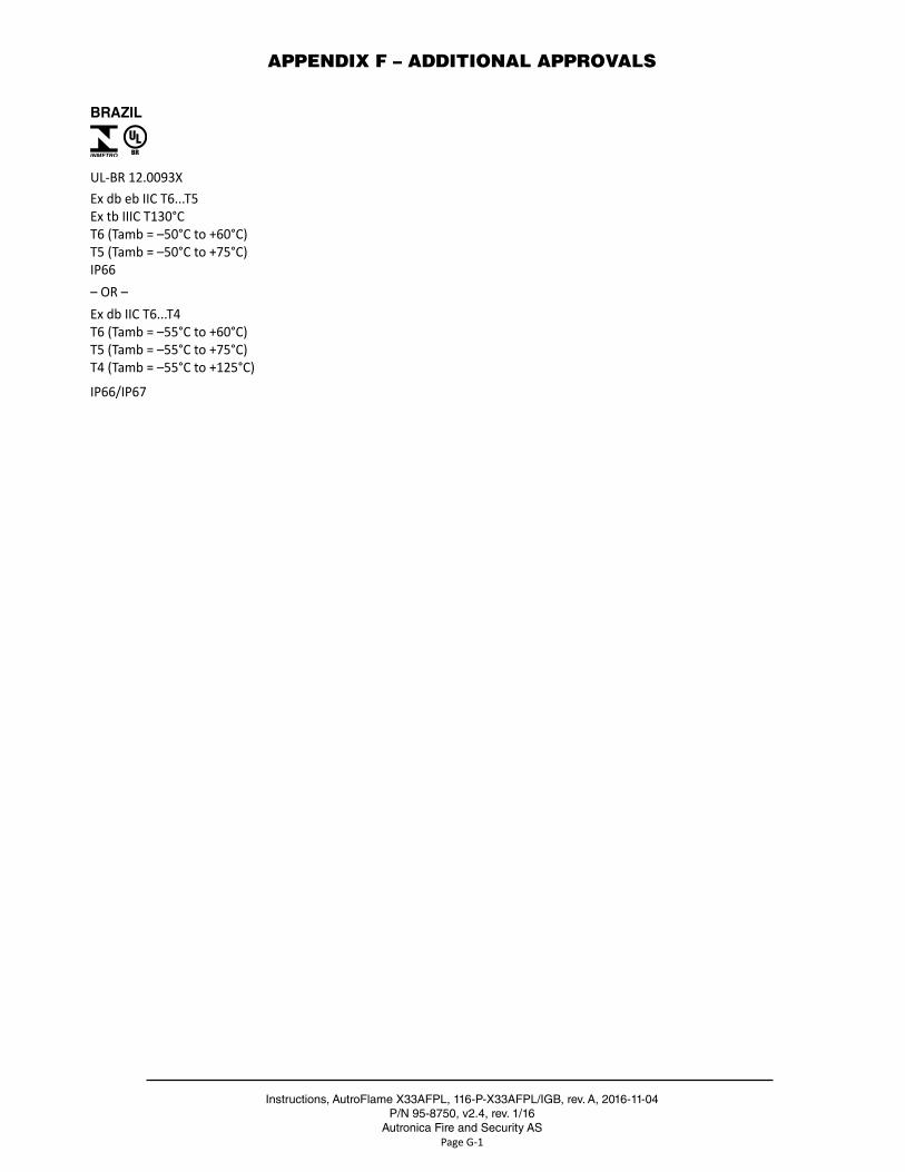
APPENDIX F – ADDITIONAL APPROVALS
BRAZIL
UL-BR 12.0093XEx db eb IIC T6...T5Ex tb IIIC T130°CT6 (Tamb = –50°C to +60°C)T5 (Tamb = –50°C to +75°C)IP66– OR –Ex db IIC T6...T4T6 (Tamb = –55°C to +60°C)T5 (Tamb = –55°C to +75°C)T4 (Tamb = –55°C to +125°C)
IP66/IP67
Instructions, AutroFlame X33AFPL, 116-P-X33AFPL/IGB, rev . A, 2016-11-04P/N 95-8750, v2 .4, rev . 1/16
Autronica Fire and Security ASPage H-1
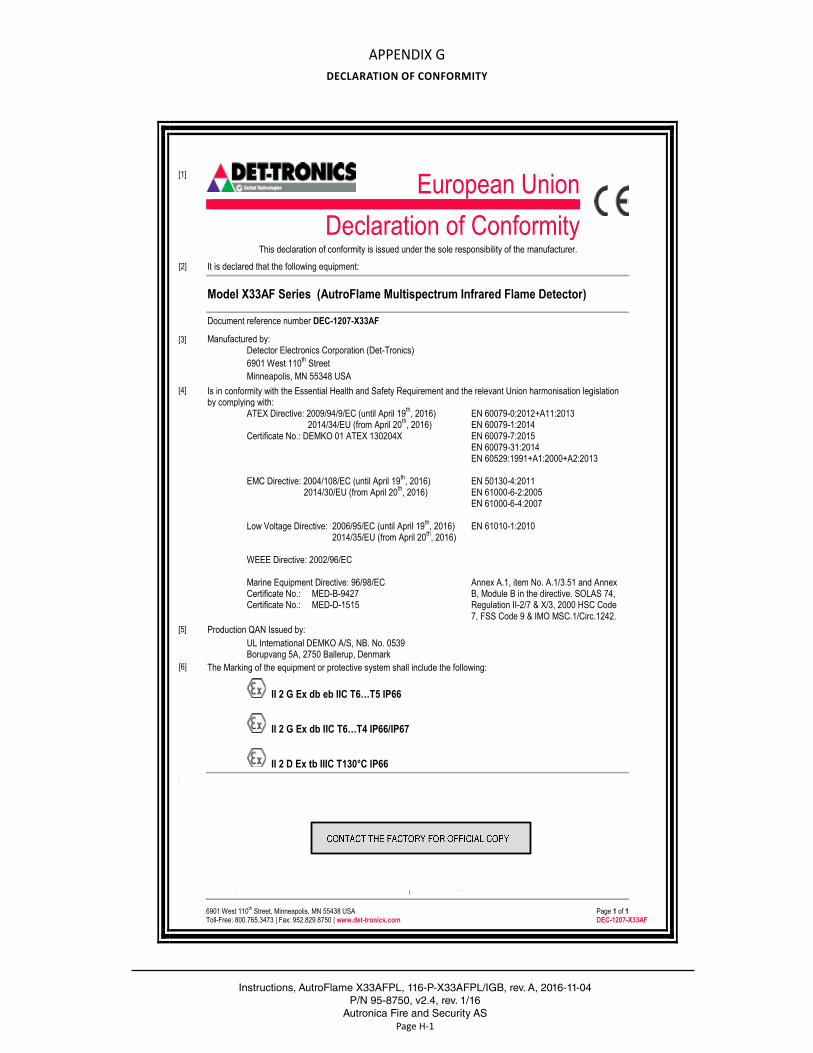
APPENDIX GDECLARATION OF CONFORMITY
6901 West 110th Street, Minneapolis, MN 55438 USA Page 1 of 1 Toll-Free: 800.765.3473 | Fax: 952.829.8750 | www.det-tronics.com DEC-1207-X33AF
[1] European Union
Declaration of Conformity This declaration of conformity is issued under the sole responsibility of the manufacturer.
[2] It is declared that the following equipment:
Model X33AF Series (AutroFlame Multispectrum Infrared Flame Detector)
Document reference number DEC-1207-X33AF
[3] Manufactured by:
Detector Electronics Corporation (Det-Tronics) 6901 West 110th Street Minneapolis, MN 55348 USA
[4] Is in conformity with the Essential Health and Safety Requirement and the relevant Union harmonisation legislation by complying with:
ATEX Directive: 2009/94/9/EC (until April 19th, 2016) 2014/34/EU (from April 20th, 2016)
Certificate No.: DEMKO 01 ATEX 130204X EMC Directive: 2004/108/EC (until April 19th, 2016)
2014/30/EU (from April 20th, 2016) Low Voltage Directive: 2006/95/EC (until April 19th, 2016)
2014/35/EU (from April 20th, 2016) WEEE Directive: 2002/96/EC Marine Equipment Directive: 96/98/EC Certificate No.: MED-B-9427 Certificate No.: MED-D-1515
EN 60079-0:2012+A11:2013 EN 60079-1:2014 EN 60079-7:2015 EN 60079-31:2014 EN 60529:1991+A1:2000+A2:2013 EN 50130-4:2011 EN 61000-6-2:2005 EN 61000-6-4:2007 EN 61010-1:2010 Annex A.1, item No. A.1/3.51 and Annex B, Module B in the directive. SOLAS 74, Regulation II-2/7 & X/3, 2000 HSC Code 7, FSS Code 9 & IMO MSC.1/Circ.1242.
[5] Production QAN Issued by: UL International DEMKO A/S, NB. No. 0539
Borupvang 5A, 2750 Ballerup, Denmark [6] The Marking of the equipment or protective system shall include the following:
II 2 G Ex db eb IIC T6…T5 IP66
II 2 G Ex db IIC T6…T4 IP66/IP67
II 2 D Ex tb IIIC T130°C IP66 [7] We, the undersigned, hereby declare that the equipment specified above conforms to the aforementioned Union
harmonisation legislation and harmonised Standard(s) for CE Conformity Marking.
Approvals Engineering Manager Operations Manager Jon Miller Sally Day
Signature: Signature:
Date of Issue: Date of Issue: Detector Electronics Corporation 6901 West 110th Street | Minneapolis, MN 55348 USA Phone: +1 (1) 952-946-6488
Detector Electronics UK Ltd. | Mathisen Way, Poyle Road Colnbrook, Slough | Berkshire SL3 OHB United Kingdom Phone: +44 (0) 1753 683059

www .autronicafire .com