Embed Size (px)
Citation preview
Instructions on installation,operation and maintenance for
Kirloskar Magnetic Drive Pump - “ROMAK”
KIRLOSKAR BROTHERS LIMITEDA Kirloskar Group Company
Established 1888
IOM/RMK/DZ1A415001-010 ISSUE DATE: 10.07.2015
Page 2 of 53 LAST REV. DATE: 10.07.2015
KIRLOSKAR BROTHERS LIMITED REGD. OFFICE UDYOG BHAVAN, TILAK ROAD PUNE-411002
WARRANTY
We warrant that the pump supplied from us is free from defective
material and faulty workmanship. This warranty holds good for a
period of 12 months from the date of commissioning the equipment
or 18 months from the date of dispatch from our factory, whichever
is earlier. Our liability in respect of any complaint is limited to
replacing part/parts free of charge ex-works or repairs of the
defective part/parts only to the extent that such replacement / repairs
are attributable or arise solely from faulty workmanship or defective
material.
This warranty holds good only for the products manufactured by us.
KIRLOSKAR BROTHERS LIMITED
IOM/RMK/DZ1A415001-010 ISSUE DATE: 10.07.2015
Page 3 of 53 LAST REV. DATE: 10.07.2015
CONTENTS
PART A: SAFETY MANUAL
PART B: INSTRUCTIONS ON INSTALLATION, OPERATION AND MAINTENANCE FOR KIRLOSKAR PUMP TYPE RMK
1. GENERAL
2. SAFETY INSTRUCTIONS
3. EQUIPMENT SCHEDULE
3.1 INSTALLATION
3.2 MOUNTING & ALIGNMENT
4. OPERATION
4.1 EQUIPMENT DESCRIPTION.
4.2 EQUIPMENT OPERATION.
5. MAINTENANCE MANUAL.
5.1 MAINTENANCE EHS INSTRUCTIONS
5.2 GENERAL MAINTENANCE DOCUMENTS
5.3 PREVENTIVE MAINTENANCE
5.4 CORRECTIVE MAINTENANCE
6 TECHNICAL DATA
Note: A copy of General instructions for installation, operation &
maintenance of ‘Kirloskar pumps’ is attached at the end of
this manual. For latest Manual Copy contact our Sales person or visit our website at
www.kirloskarpumps.com
IOM/RMK/DZ1A415001-010 ISSUE DATE: 10.07.2015
Page 4 of 53 LAST REV. DATE: 10.07.2015
PART A: SAFETY MANUAL
TRAINING
It is recommended, and a part of the CE regulations that users personnel who will be
involved in the installation, operation and/or maintenance of KBL products should have the
opportunity of an initial training period, which can be carried out either at KBL works or
customers premises by arrangement.
This training is offered by KBL in 3 different forms.
A. Informal training in your maintenance workshop by our Technical Sales Representative on
a Free of Charge basis.
B. Formal training in your training rooms by our skilled training personnel using visual aids,
‘hands on’ equipment etc, at an agreed cost to be confirmed.
C. Formal training at KBL Premises by our skilled training personnel using visual aids, ‘hands
on’ equipment, etc, at an agreed cost to be confirmed.
It is your responsibility to request your preferred training method now. KBL will not consider
responsibility for ongoing breakdowns etc, if training has not been given.
KBL offer a friendly after sales policy but, reserve the right to charge for “call out” visits
that are found to be caused through operator/fitter error.
LIMITATIONS OF USE
KBL products are designed to provide performance generally, as shown in accompanying
literature associated with the individual models or series. All performance figures are given
in good faith and are based on tests at KBL works using water at ambient temperature.
Operating temperatures are governed by the materials of construction of parts i.e. bearings,
SSiC bearings, magnets, can etc, and it is the installer’s responsibility to ensure that these
maximum temperatures are not exceeded under any circumstances.
Performance figures provided by KBL against individual enquiries are estimates only, and are
subject to variations depending upon data provided by client, and to head losses due to pipe
work, valves, etc which may be unknown to KBL estimators.
All performance figures, temperatures, flow rates, dimensions & other details are subject to
change without notice. Due to the wide variety of products handled by KBL pumps, it is
impossible for KBL to give a firm recommendation regarding materials of construction for
pump components. It is the users or specifiers responsibility to determine the effect of
corrosion & abrasion, and the general suitability of any pump supplied for any individual
application. KBL will, however, give advice in such material selection as it may be able to do
so in good faith.
ESSENTIAL SAFETY REQUIREMENTS (ESR)
All KBL products that are certified to comply with the Directive also carry a specific Safety
Manual which must be referred to in conjunction with this manual. It is the responsibility of
the user to ensure that the equipment is correctly rated for the environment in which it is to
be used.
When handling KBL products, please refer weights given in KBL literature. Lifting equipment
may be required in certain cases. Note that all pumps dispatched from our works are tested
with water and during storage, packing and installation, some water will have remained in
the pump body. This water may cause Spillage during handling. Water could react with the
products you wish to pump, and it is user responsibility to check this before putting the
IOM/RMK/DZ1A415001-010 ISSUE DATE: 10.07.2015
Page 5 of 53 LAST REV. DATE: 10.07.2015
pump into operation. Water may also freeze if the pump is exposed to sub zero
temperatures. Do not operate the pump under these conditions as ice inside the pump may
cause damage to working parts of the pump.
At all times the installer must wear suitable clothing, footwear, goggles, etc for personal
protection. This particularly applies when the pump is being operated or maintained.
If the product being processed is hazardous, then provision must be made by the user to
deal with this problem. This can be achieved by either specifying a guardian or barrier
system as part of the original pump specification and constructing pipe work which can
carry the leakage to a safe place. It is end user responsibility to comply industry safety
standards.
SAFETY MANUAL For Centrifugal RMK Pumps and Accessories User Instructions:
To be read in conjuction with
1.0 GENERAL
These instructions must always be kept close to the product’s operating location or directly
with the Product. These instructions are intended to facilitate familiarization with the
product and its permitted use to help satisfy safety requirements.
The instructions may not have taken into account local regulations; ensure such regulations
are observed by all, including those installing the product. Always co-ordinate repair activity
with operations personnel, and follow all plant safety requirements and applicable safety
and health/law regulations. These instructions should be read prior to installing, operating,
using and maintaining the equipment in any region worldwide and in conjunction with the
main user instructions provided. The equipment must not be put into service until all the
conditions relating to safety instructions have been met.
A.1
It is a legal requirement that machinery and equipment put into service within certain
regions of the world shall conform to the applicable CE Marking Directives for Equipment for
Potentially Explosive Atmospheres (ATEX).
Where applicable the Directive covers important safety aspects relating to the equipment,
its use and the satisfactory provision of technical documents. Where applicable this
document incorporates information relevant to these Directives. To establish if the product
itself is CE marked for a Potentially Explosive Atmosphere check the nameplate and the
Certification provided.
A.1.1 Disclaimer
Information in these User Instructions is believed to be reliable. In spite of all the efforts of
KIRLOSKAR BROTHERS LTD. to provide sound and all necessary information, the content of
this Manual may appear insufficient and is not guaranteed by KIRLOSKAR BROTHERS LTD.
as to its completeness or accuracy. However KIRLOSKAR BROTHERS LTD will not accept
responsibility for physical injury, damage, loss of user production by failure to observe the
instructions for installation, operation and maintenance contained in this complete Manual.
A.2 Personnel qualifications and training
All personnel involved in the operation, installation, inspection and maintenance of the unit
must be qualified to carry out the work involved. If the personnel in question do not already
possess the necessary knowledge and skill, appropriate training and instruction must be
provided. If required the operator may commission the manufacturer/supplier to provide
applicable training.
IOM/RMK/DZ1A415001-010 ISSUE DATE: 10.07.2015
Page 6 of 53 LAST REV. DATE: 10.07.2015
A.3 CE Marking & Approvals
General:
It is a legal requirement that the machinery & equipment put into service in certain region of
the world shall conform with the applicable CE marking directives covering pump,
accessories & instruments in the package.
Kirloskar pumps RMK range of pumps are certified to comply with the European Directive
2006/42/EC.
Check the product nameplate & certification provided to establish that the product itself is
CE marked for Potentially Explosive Atmosphere.
A.4 Avoiding excessive surface temperatures
ENSURE THE EQUIPMENT TEMPERATURE CLASS IS SUITABLE FOR THE HAZARD ZONE if
applicable.
A.4.1 Pump liquid temperature
The surface temperature of the pump may be influenced by the temperature of the liquid
handled. The temperature rise at ball bearings, liquid temperature and due to the minimum
permitted flow rate is taken into account in the temperatures.
Maximum permitted pumping liquid temperature for RMK pumps is 180°C.
Maximum permitted temperature of casing, casing cover surface depends of material of
construction. However same should not be exceed maximum permitted pumping liquid
temperature.
Where there is any risk of the pump being run for prolonged periods against a closed or
partially closed valve generating high liquid and casing external surface temperatures, it
recommended that users fit an external surface temperature protection device.
A.4.2 Additional requirements for dry run protection conditions
Where the system operation does not ensure control of priming, and the bearings will run
dry, in this case temperature of surface could be exceeded than normal, it is recommended
for users to fit an external dry run protection device.
A.5 Preventing the build up of explosive mixtures
ENSURE PUMP IS PROPERLY FILLED WHENEVER POSSIBLE AND DOES NOT RUN DRY IN
ANY CASE.
Ensure the pump and relevant suction and discharge pipeline system is totally filled with
liquid during the pumping operation, so that an explosive atmosphere is prevented. If the
operation of the system cannot avoid this condition, ensure that the pump does not run dry
IN ANY GIVEN CASE.
To avoid potential hazards from fugitive emissions of vapour or gas to atmosphere the
surrounding area must be well ventilated.
A.6 Preventing sparks
To avoid the potential hazard from random induced current generating a spark, the earth
stud on the pump casing or foot must be connected. Avoid electrostatic charge: Do not rub
non-metallic surfaces with a dry cloth for cleaning etc; ensure the cloth is damp.
A.7 Preventing leakage
The pump must only be used to handle liquids for which it has been approved to have the
correct corrosion resistance. Avoid entrapment of liquid in the pump and associated piping
due to closing of suction and discharge valves, which could cause dangerous excessive
pressures to occur if there is heat input to the liquid. This can occur particularly if the pump
IOM/RMK/DZ1A415001-010 ISSUE DATE: 10.07.2015
Page 7 of 53 LAST REV. DATE: 10.07.2015
is stationary. Bursting of liquid containing parts due to freezing, must be avoided by draining
or protecting the pump and ancillary systems. If leakage of liquid to atmosphere can result
in a hazard, the installation of a liquid detection device is recommended.
A.8 Maintenance of the RMK pump to avoid the hazard
CORRECT MAINTENANCE IS REQUIRED TO AVOID POTENTIAL HAZARDS WHICH GIVE A
RISK OF EXPLOSION
The responsibility for compliance with maintenance instructions is with the plant operator.
To avoid potential explosive hazards during maintenance, the tools, cleaning and painting
materials used must not give rise to sparking or adversely affect the ambient conditions.
Where there is a risk from such tools or materials, maintenance must be conducted in a safe
area.
It is recommended that a maintenance plan and schedule is adopted, in line with the user
instructions provided, to include the following:-
A:- Any auxiliary systems installed must be monitored, if necessary, to ensure they function
correctly.
B:- Check for any leaks from gaskets.
C:- Check that the duty condition is in the safe operating range for the pump.
D:- Check that dirt and dust is removed from operational areas of the pump.
E:- Inspect the RMK pumps at least every 1000 running hours and renew if any sign of
damage is apparent.
A.9 Additional Safety Instructions
A) Pumps and ancillary equipment must be drained, cleaned and decontaminated prior to
any change of duty.
B) Where pumps and ancillary equipment contain non-conductive plastic wetted
components, dismantling for maintenance must take place in a safe area away from the
flammable hazard, or the equipment made safe by purging with nitrogen.
C) When installing a pump either for the first time or after maintenance, a check must be
made to ensure that the earth connection terminal on the pump and any external
metalwork is at ground potential.
D) Where a counter or count and stop device is fitted, it is for indicating the number of
cycles run only, and not to use as a means of process flow control or for performing a
safety function.
E) Ensure nozzle forces and bending moments should not exceed the maximum permissible
values as specified in technical documents.
F) Never heat the impeller to remove same as in case of trapped pumping fluid if hazardous
may result into explosion.
IOM/RMK/DZ1A415001-010 ISSUE DATE: 10.07.2015
Page 8 of 53 LAST REV. DATE: 10.07.2015
PART B: INSTRUCTIONS ON INSTALLATION, OPERATION AND MAINTENANCE FOR KIRLOSKAR PUMP TYPE RMK
1. GENERAL
1.1 ‘KIRLOSKAR’ make RMK pumps are used for handling various types of CLEAR &
CLEAN chemical liquids with leak free transportation. These pumps are
manufactured to close tolerance and are of rigid construction, However proper
installation, operation and maintenance are equally important to ensure trouble free
service. This booklet covers important guidelines and instructions for installation,
operation and maintenance. These instructions should be followed carefully for
satisfactory performance of the pumping unit. Only mechanical aspects are dealt
within this booklet.
1.2 Applications:
RMK pumps are mainly used in process industries like petrochemicals, nuclear,
refinery, fertilizer, paper, sugar etc. and power plants. The pump can handle
corrosive acids, alkalies, salt solutions, caustics, hydro-carbons, oils, liquefied
gases, condensates, viscous liquids etc. Use for application involving entrained
gases, fumes & solids is not permitted to avoid dry running of pumps.
1.3 Nomenclature: RMK32/13-1R
RMK – Kirloskar ROMAK Pump
32 - Delivery size in mm
13 - Impeller diameter in cm.
1R - 1 Ring (Pair of Magnet rings)
1.4 This booklet covers instructions for following models
Drive unit 5
5.1 32/13 40/13 50/13 65/13
5.2 32/16 40/16 50/16 32/16A 50/16A
5.3 32/20 40/20 50/20 32/20A 40/20A
Drive unit 7
7.1 65/16 80/16
7.2 65/20 80/20 100/20
7.3 32/26 40/26 50/26 65/26 80/26
7.4 40/32 50/32
1.5 Nameplate information:
Every pump has the nameplate fitted to bearing housing provided with necessary
identification of the pump and its specific hydraulic characteristics.
The nameplate of pump must not be removed. Loss of this plate could make
identification impossible. This in turn could affect safety and cause difficulty in
obtaining spare parts.
IOM/RMK/DZ1A415001-010 ISSUE DATE: 10.07.2015
Page 9 of 53 LAST REV. DATE: 10.07.2015
1.6 Pumps when properly installed & given due care in operation & maintenance should
operate satisfactorily for a long period.
1.7 When the pump is received, sometime before the actual use of pump, it should be
inspected & located in dry place. The coupling should be rotated once in a month to
prevent pitting of bearing surfaces.
1.8 Tightening Torque values for major pressurized fasteners.
Casing
(58100,58101)
Casing
(58100,58101)
Size No. Size
Torque,
Nm Size No. Size
Torque,
Nm
1 32/13 8 M8 18 12 80/16 8 M10 35
2 40/13 8 M8 18 13 65/20 8 M12 55
3 50/13 8 M8 18 14 80/20 8 M12 55
4 65/13 8 M8 18 15 100/20 8 M12 55
5 32/16,32/16A 8 M10 35 16 32/26 12 M12 55
6 40/16 8 M10 35 17 40/26 12 M12 55
7 50/16,50/16A 8 M10 35 18 50/26 12 M12 55
8 32/20,32/20A 8 M12 55 19 65/26 12 M12 55
9 40/20,40/20A 8 M12 55 20 80/26 12 M12 55
10 50/20 8 M12 55 21 40/32 12 M12 70
11 65/16 8 M10 35 22 50/32 12 M12 70
IOM/RMK/DZ1A415001-010 ISSUE DATE: 10.07.2015
Page 10 of 53 LAST REV. DATE: 10.07.2015
Can (57800) Bearing holder (57400)
Unit No. Size
Torque,
Nm Unit No. Size
Torque,
Nm
1 5.1 6 M8 15 1 5.1 3 M8 12
2 5.2,5.3 6 M8 20 2 5.2,5.3 3 M8 12
3 7.2 8 M8 20 3 7.1,7.2,7.3,7.4 3 M8 12
4 7.1,7.3,7.4 8 M10 35
Impeller Nut with helicoil insert
(33000)
Drive unit No. Size
Torque,
Nm
1 5 1 M16 70
2 7 1 M18 100
1.9 Contact Information
KIRLOSKAR BROTHERS LIMITED
REGD. OFF:
UDYOG BHAVAN,TILAK ROAD,
PUNE-41102 (INDIA)
CORPORATE OFFICE: “YAMUNA”,
SURVEY NO-98/3-7,
PUNE MUMBAI HIGHWAY,
BANER, PUNE -411 045 (INDIA)
WORKS:
KIRLOSKARWADI,
416308 ,
DIST.:SANGLI (INDIA)
TEL: 091 020- 2440 0770
FAX: 091 020- 2427 0156
TEL: 091 020- 2721 4444
FAX: 091 020- 2427 0879
TEL: 091 02346- 221 055
FAX: 091 02346- 222 311
Note: The information in this document may sometimes be of generic nature and
applicable to various company products irrespective of its specific application &
use. Additional instructions if any shall be specified on individual project
drawings & documents furnished to the buyer against specific order.
Where a conflict exists between the contents herein and the actual equipment
supplied, the user must make an engineering judgment, else contact KBL.
Kirloskar Brothers reserves the right to change the construction & design of the
products at any time without being obliged to change products already supplied
earlier.

IOM/RMK/DZ1A415001-010 ISSUE DATE: 10.07.2015
Page 11 of 53 LAST REV. DATE: 10.07.2015
2. Safety Instructions:
2.1: General Information
Before performing any actions detailed within this instruction, the Site Health and
Safety instructions shall be read and fully understood. The instructions in this
document shall also be read and fully understood.
Whenever the equipment is operated, maintained or used in any way, the
procedures detailed within the Health and Safety Dossier (DHS) and any procedures
detailed within these instructions shall be followed. The pump supplied by Kirloskar
Brothers Limited (KBL) has been designed with safety in mind; where hazards
cannot be eliminated, the risk has been minimized by the use of guards and other
design features. Some hazards cannot be guarded against and the instructions
below MUST BE COMPLIED WITH for safe operation. These instructions cannot
cover all circumstances. It is the responsibility of the user of the equipment for
maintaining safe working practices at all times. The pumps are supplied with
stickers for hazard, caution and safety wherever these are applicable.
2.1.1 Within the manual, safety instructions are marked with safety symbols. Hazard.
This symbol refers to general mechanical aspects of safety.
Hazard.
This symbol refers to electrical safety.
This symbol is used to introduce safety instructions whose non-
Observance may lead to damage to the machine and its functions.
This symbol refers to magnetic field safety.
This symbol refers to restrict person with having heart
pacemaker to avoid contact with magnetic components while
pump is in running condition or while carrying out maintenance
work of pump.
2.1.2 KBL products are designed for installation in designated areas, which are to be kept
clean and free of obstructions that may restrict safe access to the controls and
maintenance access points.
Pump nameplate is fitted to each unit and must not be removed. Loss of this plate
could make identification impossible. This in turn could affect safety and cause
IOM/RMK/DZ1A415001-010 ISSUE DATE: 10.07.2015
Page 12 of 53 LAST REV. DATE: 10.07.2015
difficulty in obtaining spare parts. Should accidental loss or damage occur, contact
KBL immediately.
2.1.3 Access to the equipment should be restricted to the personnel responsible for
installation, operation and maintenance and they must be trained, adequately
qualified and supplied with the appropriate tools for their respective tasks.
2.1.4 KBL firmly insists that all personnel responsible for installation, operation and
maintenance of the equipment must read the manual before any work is done.
2.1.5 Ear defenders should be worn where the specified equipment noise level exceeds
locally defined safe levels. Safety glasses or goggles should be worn where working
with pressurized systems and hazardous substances. Other personal protection
equipment must be worn where local rules apply.
2.2 DO NOT wear loose or frayed clothing or jewellery, which could
catch on the controls or becomes trapped in the equipment.
2.3 Operation of the equipment for the application other than for which it is supplied
can increase the risk from hazards. Please consult KBL before making such change
in the application of the equipment.
2.4 Improper installation, operation and maintenance of the product supplied by KBL
could result in injury or death.
2.5 In case of RMK pumps which are handling fluid at high temperature,
the operator should avoid touching the pump in running condition. Use safety
equipments like hand gloves and safety shoes while operating RMK pumps in such
applications.
2.6: Transport handling and storage instructions:
2.6.1: Transport.
Pumps are dispatched in duly assembled condition. Lubricating oil in the bearing
housing is drained prior to dispatch of pump. Pumps are protected against corrosion and
packed for transport by normal road, rail and sea carriers.
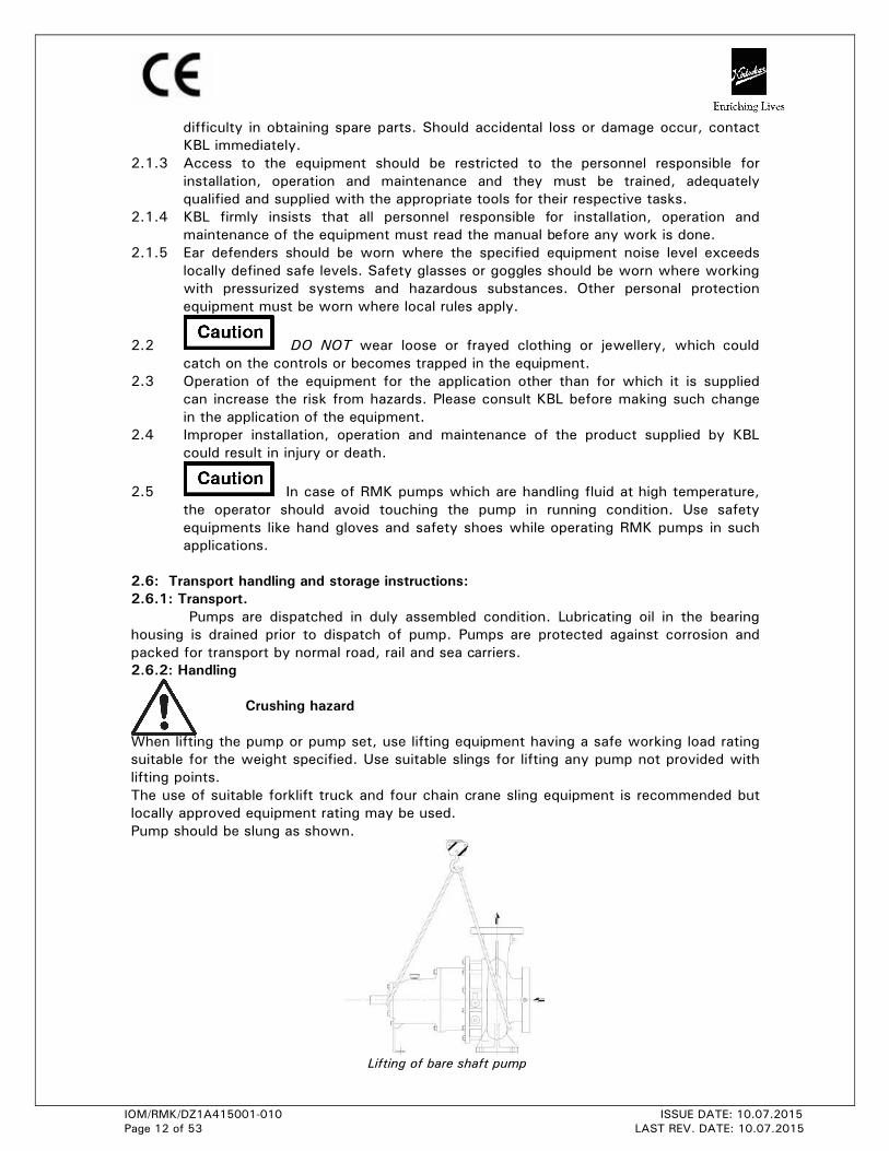
2.6.2: Handling
Crushing hazard
When lifting the pump or pump set, use lifting equipment having a safe working load rating
suitable for the weight specified. Use suitable slings for lifting any pump not provided with
lifting points.
The use of suitable forklift truck and four chain crane sling equipment is recommended but
locally approved equipment rating may be used.
Pump should be slung as shown.
Lifting of bare shaft pump
IOM/RMK/DZ1A415001-010 ISSUE DATE: 10.07.2015
Page 13 of 53 LAST REV. DATE: 10.07.2015
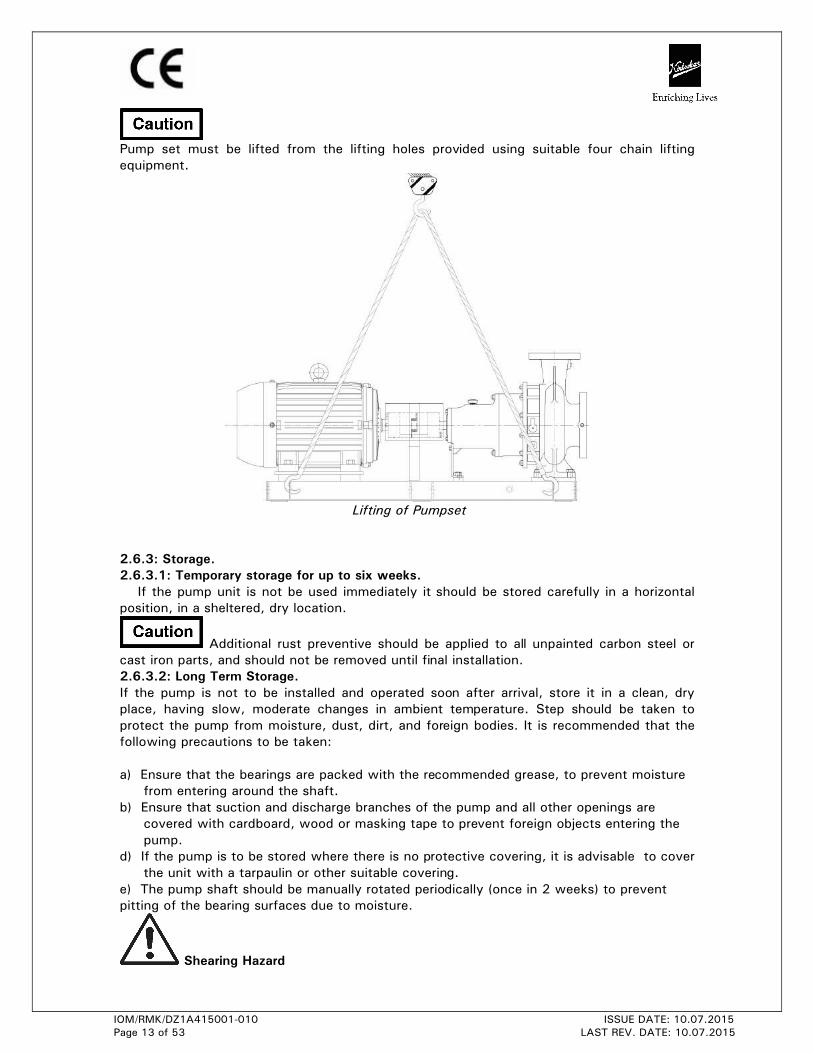
Pump set must be lifted from the lifting holes provided using suitable four chain lifting
equipment.
Lifting of Pumpset
2.6.3: Storage.
2.6.3.1: Temporary storage for up to six weeks.
If the pump unit is not be used immediately it should be stored carefully in a horizontal
position, in a sheltered, dry location.
Additional rust preventive should be applied to all unpainted carbon steel or
cast iron parts, and should not be removed until final installation.
2.6.3.2: Long Term Storage.
If the pump is not to be installed and operated soon after arrival, store it in a clean, dry
place, having slow, moderate changes in ambient temperature. Step should be taken to
protect the pump from moisture, dust, dirt, and foreign bodies. It is recommended that the
following precautions to be taken:
a) Ensure that the bearings are packed with the recommended grease, to prevent moisture
from entering around the shaft.
b) Ensure that suction and discharge branches of the pump and all other openings are
covered with cardboard, wood or masking tape to prevent foreign objects entering the
pump.
d) If the pump is to be stored where there is no protective covering, it is advisable to cover
the unit with a tarpaulin or other suitable covering.
e) The pump shaft should be manually rotated periodically (once in 2 weeks) to prevent
pitting of the bearing surfaces due to moisture.
Shearing Hazard
IOM/RMK/DZ1A415001-010 ISSUE DATE: 10.07.2015
Page 14 of 53 LAST REV. DATE: 10.07.2015
DO NOT place fingers or hands etc. into the suction or discharge pipe outlets and do
NOT touch the impeller, if rotated this may cause severe injury. To prevent ingress of any
objects, retain the protection covers or packaging in place until removal is necessary for
installation. If the packaging or suction and discharge covers are removed for inspection
purposes, replace afterwards to protect the pump and maintain the safety.
Fill the bearing housing with recommended oil to ensure that the shaft and bearings remain
rust free.
2.6.3.3: Exposed or Extreme Conditions Storage.
For exposed storage or extreme variants in atmospheric or environmental conditions, please
refer to KBL for special storage instructions to suit the conditions acceptable.
3. Equipment schedule:
3.1 INSTALLATION:
3.1.1 For location, preparing foundation, installation, alignment, piping, general
maintenance, trouble shooting etc. the instructions given in our publication -
’GENERAL INSTRUCTIONS FOR INSTALLATION, OPERATION AND MAINTENANCE
OF KIRLOSKAR CENTRIFUGAL PUMPS’ which is also printed along this booklet
must be followed very carefully. If the pump is drawing liquid from the vessel under
vacuum, then vacuum equalizing connection piping must be made as per instruction
given in above publication. The external sealing connection to the pump, if
applicable, must be made after installing and before commissioning the pump. Pump
on hot service must have final coupling alignment made with the unit at its
operating temperature.
3.1.2 Receiving pump
Upon receipt of the pump, a visual check should be made to determine if any
damage occurred during transit or handling. The main items to look for are:-
a) Broken or cracked equipment, including base, motor or pump feet and
flanges.
b) Bent of shaft
c) Broken motor end bells, bent eyebolts or damaged boxes of motor
d) Missing parts.
e) Pump shaft rotates freely.
Parts or accessories are some times wrapped individually or fastened to the
equipment. If any damage or losses have been incurred; promptly notify your KBL
representative, KBL Dealer and the transport company who delivered the pump.
When unloading pump units, lift equally at four or more points from the base.
DO NOT LIFT ONLY THE DRIVER OR PUMP.
3.1.3 Preparation
• Before installing the pump, clean the suction and discharge flanges thoroughly.
• Remove the protective coating from the pump shaft.
• If the pump has been in storage and prepared for storage in the manner outlined
previously, remove all the grease from the bearings. The bearings should then be
flushed with carbon tetrachloride or kerosene and relubricated.
3.1.4 Location
• The pump should be installed as near the liquid source as possible, with the shortest
and most direct suction pipe practically.
IOM/RMK/DZ1A415001-010 ISSUE DATE: 10.07.2015
Page 15 of 53 LAST REV. DATE: 10.07.2015
• The pump should be installed with sufficient accessibility for inspection and
maintenance. Ample space and head room should be allowed for the use of an
overhead crane or hoist sufficiently strong to lift the unit.
• Make sure there is a suitable power source available for the pump driver. If motor
driven, electrical characteristics should be identical to those shown on motor data/
name plate.
3.1.5 Foundation
• The foundation should be strong enough to reduce vibrations and rigid enough to avoid any twisting or misalignment.
• The foundation should be poured without interruptions to within 20 to 40 mm of the finished height. The top surface of the foundation should be well scored and glued
before the concrete sets. This provides a bonding surface for the grout. Foundation
bolts should be set in concrete as shown in fig. Allow enough bolt length for grout,
shims, lower base plate flange, nuts and washers. The foundation should be allowed
to cure for several days before the base plate is shimmed and grouted.
3.1.6 Base plate setting
• Use blocks and shims under base for support at foundation bolts and midway between bolts, to position base approximately 25 mm above the concrete foundation with
studs extending through hole in the base plate.
• By adding or removing shims under the base, level the pump shaft and flanges. The base plate does not have to be leveled. Draw foundation bolt nuts tight against base
plate and observe pump and motor shafts or coupling hubs for alignment.
• Check to make sure the piping can be aligned to pump flanges without placing pipe strain on either flange.
• Grout base plate in completely and allow grout to dry thoroughly before attaching piping to pump (24 hours is sufficient time with approved grouting procedure).
3.1.7 Grouting procedure
Grout compensates for uneven foundation, distributes weight of unit and prevents
shifting. Use an approved, non-shrinking grout as follows, after setting and leveling
unit
• Build strong form around foundation to content grout. • Soak top of concrete foundation thoroughly, then remove surface water. • Base plate should be completely filled with grout and, if necessary, drill vent holes to remove trapped air.
• After grout has thoroughly hardened, check the foundation bolts and tighten if necessary.
• Check the alignment after the foundation bolts are tightened. • Approximately 14 days after the grout has been poured or when the Grout has thoroughly dried, apply an oil base paint to the exposed edges of the grout to prevent
from air and moisture coming in contact with the grout.
3.1.8 Suction and Discharge Piping
When installing the pump piping, make sure to observe the following precautions:-
• Piping should always run to the pump. Do not move pump to pipe. This could make final alignment impossible.
• Both suction and discharge piping should be supported independently and close to pump so that no strain is transmitted to the pump when the flange bolts are
tightened.
IOM/RMK/DZ1A415001-010 ISSUE DATE: 10.07.2015
Page 16 of 53 LAST REV. DATE: 10.07.2015
• Use pipe hangers or other supports at necessary intervals to provide support. When expansion joints are used in the piping system, they must be installed beyond the
piping supports close to the pump.
• It is advisable to increase the size of both suction and discharge pipes at the pump connection to decrease the loss of head from friction. Suction velocity to be restricted
to 1.5 to 2 m/s & Discharge velocity to be restricted to 2.5 to 3 m/s.
• Install piping as straight as possible, avoiding unnecessary bends. Where necessary, use long sweep 90 degree bend to decrease friction losses.
• Make sure that all piping joints are air tight. Provide pipe expansions bellows when hot fluids are to be pumped. Where reducers are used, eccentric reducers are to be fitted in suction lines and straight taper reducers in discharge and vertical lines.
• Misuse of reducers may cause the formation of air pockets in the pipe and thus preventing the correct operation of the pump.
• The suction pipe should be as short & direct as possible. Where suction lift is not very high, it is advisable to use a foot valve. Horizontal suction line must have a gradual
rise to the pump.
• The discharge pipe is usually preceded by a non-return valve or check valve and a discharge gate valve. The check valve is to protect the pump from excessive back
pressure and reverse rotation of the unit and to prevent back flow into the pump in
case of stoppage or failure of the driver. The discharge valve is used in priming,
starting and when shutting down the pump.
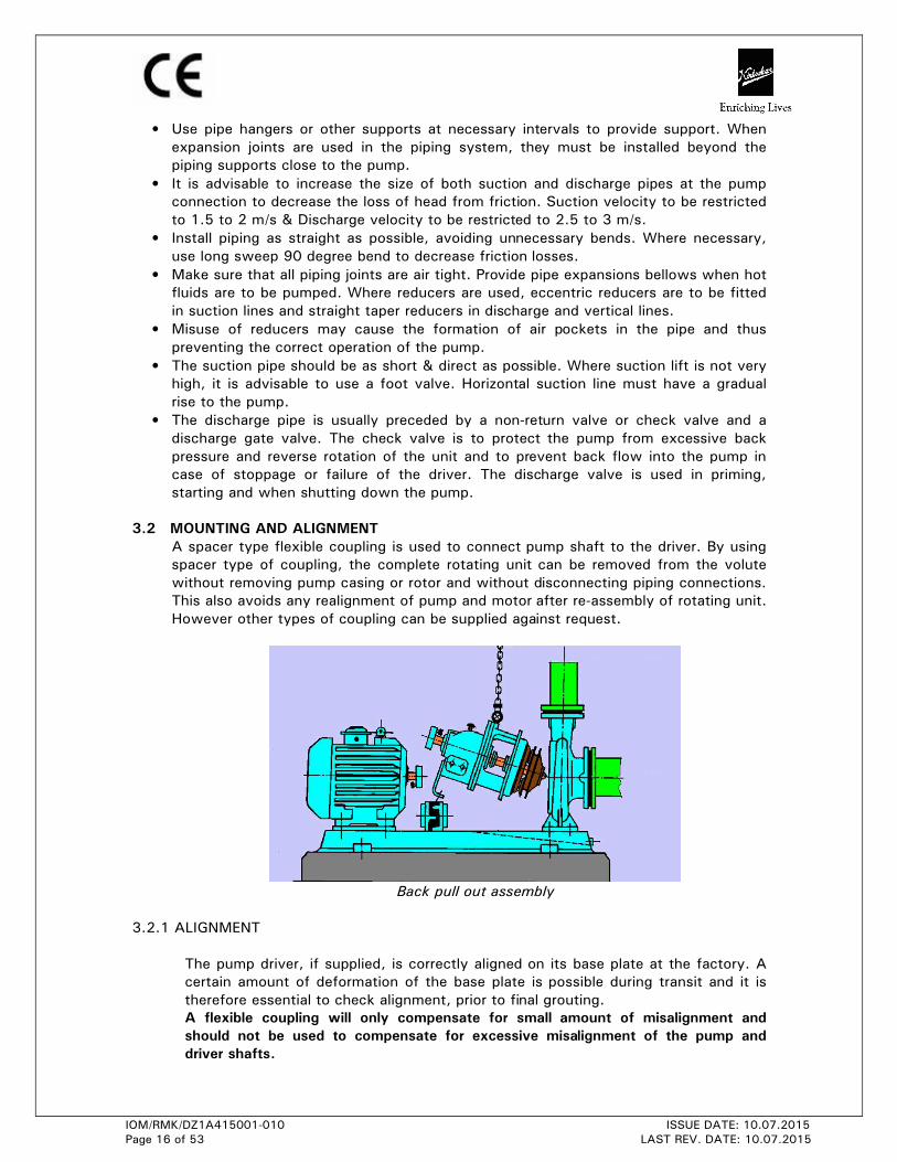
3.2 MOUNTING AND ALIGNMENT
A spacer type flexible coupling is used to connect pump shaft to the driver. By using
spacer type of coupling, the complete rotating unit can be removed from the volute
without removing pump casing or rotor and without disconnecting piping connections. This also avoids any realignment of pump and motor after re-assembly of rotating unit.
However other types of coupling can be supplied against request.
Back pull out assembly
3.2.1 ALIGNMENT
The pump driver, if supplied, is correctly aligned on its base plate at the factory. A
certain amount of deformation of the base plate is possible during transit and it is
therefore essential to check alignment, prior to final grouting.
A flexible coupling will only compensate for small amount of misalignment and
should not be used to compensate for excessive misalignment of the pump and
driver shafts.
IOM/RMK/DZ1A415001-010 ISSUE DATE: 10.07.2015
Page 17 of 53 LAST REV. DATE: 10.07.2015
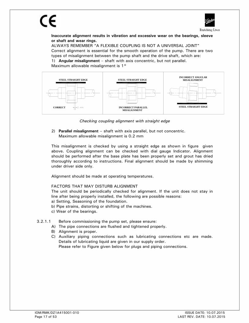
CORRECT
STEEL STRAIGHT EDGE
INCORRECT PARALLEL MISALIGNMENT
STEEL STRAIGHT EDGE
STEEL STRAIGHT EDGE
INCORRECT ANGULAR MISALIGNMENT
Inaccurate alignment results in vibration and excessive wear on the bearings, sleeve
or shaft and wear rings.
ALWAYS REMEMBER “A FLEXIBLE COUPLING IS NOT A UNIVERSAL JOINT”
Correct alignment is essential for the smooth operation of the pump. There are two
types of misalignment between the pump shaft and the drive shaft, which are:
1) Angular misalignment – shaft with axis concentric, but not parallel. Maximum allowable misalignment is 1°
Checking coupling alignment with straight edge
2) Parallel misalignment – shaft with axis parallel, but not concentric. Maximum allowable misalignment is 0.2 mm
This misalignment is checked by using a straight edge as shown in figure given
above. Coupling alignment can be checked with dial gauge Indicator. Alignment
should be performed after the base plate has been properly set and grout has dried
thoroughly according to instructions. Final alignment should be made by shimming
under driver side only.
Alignment should be made at operating temperatures.
FACTORS THAT MAY DISTURB ALIGNMENT
The unit should be periodically checked for alignment. If the unit does not stay in
line after being properly installed, the following are possible reasons:
a) Setting, Seasoning of the foundation.
b) Pipe strains, distorting or shifting of the machines.
c) Wear of the bearings.
3.2.1.1 Before commissioning the pump set, please ensure:
A) The pipe connections are flushed and tightened properly. B) Alignment is proper. C) Auxiliary piping connections such as lubricating connections etc are made.
Details of lubricating liquid are given in our supply order.
Please refer to Figure given below for plugs and piping connections.
IOM/RMK/DZ1A415001-010 ISSUE DATE: 10.07.2015
Page 18 of 53 LAST REV. DATE: 10.07.2015
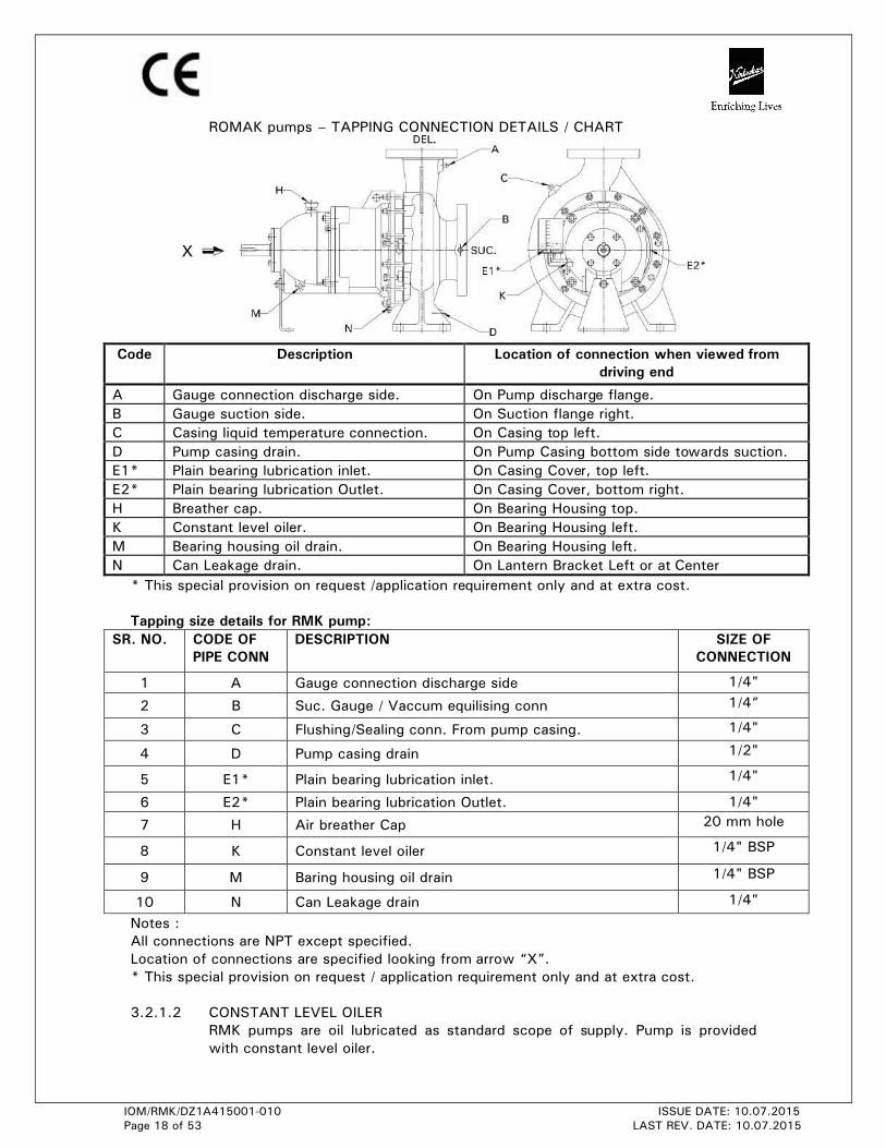
ROMAK pumps – TAPPING CONNECTION DETAILS / CHART
* This special provision on request /application requirement only and at extra cost.
Tapping size details for RMK pump:
SR. NO. CODE OF
PIPE CONN
DESCRIPTION SIZE OF
CONNECTION
1 A Gauge connection discharge side 1/4"
2 B Suc. Gauge / Vaccum equilising conn 1/4”
3 C Flushing/Sealing conn. From pump casing. 1/4"
4 D Pump casing drain 1/2"
5 E1* Plain bearing lubrication inlet. 1/4"
6 E2* Plain bearing lubrication Outlet. 1/4"
7 H Air breather Cap 20 mm hole
8 K Constant level oiler 1/4" BSP
9 M Baring housing oil drain 1/4" BSP
10 N Can Leakage drain 1/4"
Notes :
All connections are NPT except specified.
Location of connections are specified looking from arrow “X”.
* This special provision on request / application requirement only and at extra cost.
3.2.1.2 CONSTANT LEVEL OILER
RMK pumps are oil lubricated as standard scope of supply. Pump is provided
with constant level oiler.
Code Description Location of connection when viewed from
driving end
A Gauge connection discharge side. On Pump discharge flange.
B Gauge suction side. On Suction flange right.
C Casing liquid temperature connection. On Casing top left.
D Pump casing drain. On Pump Casing bottom side towards suction.
E1* Plain bearing lubrication inlet. On Casing Cover, top left.
E2* Plain bearing lubrication Outlet. On Casing Cover, bottom right.
H Breather cap. On Bearing Housing top.
K Constant level oiler. On Bearing Housing left.
M Bearing housing oil drain. On Bearing Housing left.
N Can Leakage drain. On Lantern Bracket Left or at Center
IOM/RMK/DZ1A415001-010 ISSUE DATE: 10.07.2015
Page 19 of 53 LAST REV. DATE: 10.07.2015
Fix the constant level oiler and fill the oil. Procedure for fitting the constant level
oiler and the method of filling oil is given below.
Constant level oiler has plastic container in Aluminium body as a standard
supply. Connection stem is ¼ inch BSP tapped and its capacity is 70 ml
approximately. If the constant level oiler is properly fitted and oil is filled as per
instructions given, practically no attention is required as far as lubrication of
bearing is concerned other than to replenish the visible reserve supply of the oil
in the container ref figure given below. (For other make constant level oiler
available in market (if supplied) refer respective catalogue / operating manual.)
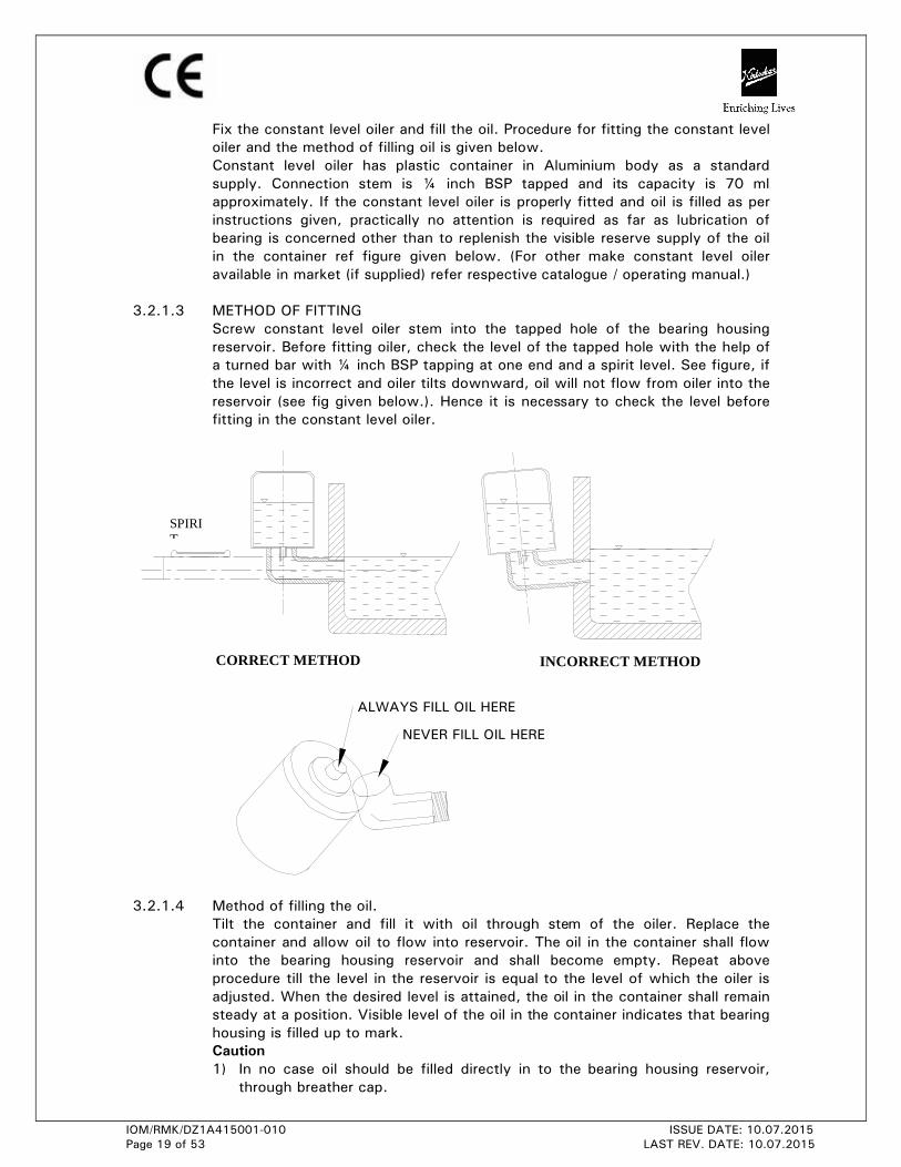
3.2.1.3 METHOD OF FITTING
Screw constant level oiler stem into the tapped hole of the bearing housing
reservoir. Before fitting oiler, check the level of the tapped hole with the help of
a turned bar with ¼ inch BSP tapping at one end and a spirit level. See figure, if
the level is incorrect and oiler tilts downward, oil will not flow from oiler into the
reservoir (see fig given below.). Hence it is necessary to check the level before
fitting in the constant level oiler.
3.2.1.4 Method of filling the oil.
Tilt the container and fill it with oil through stem of the oiler. Replace the
container and allow oil to flow into reservoir. The oil in the container shall flow
into the bearing housing reservoir and shall become empty. Repeat above
procedure till the level in the reservoir is equal to the level of which the oiler is
adjusted. When the desired level is attained, the oil in the container shall remain
steady at a position. Visible level of the oil in the container indicates that bearing
housing is filled up to mark.
Caution
1) In no case oil should be filled directly in to the bearing housing reservoir, through breather cap.
CORRECT METHOD INCORRECT METHOD
SPIRIT
NEVER FILL OIL HERE
ALWAYS FILL OIL HERE
IOM/RMK/DZ1A415001-010 ISSUE DATE: 10.07.2015
Page 20 of 53 LAST REV. DATE: 10.07.2015
2) Replenish the visible reserve supply of oil in the container as oil is used up. 3) Please ensure that air ‘GROOVE’ provided on Aluminum body on which
plastic container rests is not clogged with dust / fiber oil film etc. this groove
allows atmospheric air to enter inside the body, to maintain oil level in
bearing housing.
4. Operation.
4.1 EQUIPMENT DESCRIPTION:
End suction centrifugal pump type RMK is from KBL manufactured process pump
series which dimensionally conforms to DIN 24256 / ISO 2858 & technically
meeting requirements of ISO5199.
The mechanical assembly comprises a rigid shaft, supported by a pair of bearings,
Permanent Magnet assemblies mounted on rotors, in between can with a enclosed
impeller mounted on plain bearing assemblies. This is attached to an end suction
volute casing fitted with wear rings. The ball bearing housing, magnet assembly,
plain bearing assembly and impeller assembly can be withdrawn from the volute for
maintenance without disconnection of pipe work.
The discharge branch is positioned vertically upwards while suction branch is
horizontal and is at 90° to discharge nozzle. An additional mounting foot is fitted at
the outer bearing position for stability.
Refer general cross sectional assembly & Exploded view of pump provided at end of
this leaflet to get better idea of pump design.
The complete assembly is of rigid construction, being intended for mounting on
suitable base plate with electric motor / internal combustion engine. A suitable
coupling is provided to transmit the rotational drive between pump and motor. A
spacer coupling most suitable to use, because it allows the removal of the pump
rotating assembly without disconnecting suction pipe, discharge pipe and motor.
4.2 EQUIPMENT OPERATION.
Never run ROMAK pumps in dry condition. Internal plain bearings will fail
immediately if pumps are run in dry condition.
4.2.1 Before starting the pump check the following:
1) The pump rotates freely by hand. 2) The level of the oil in the constant level oiler is up to the mark. 3) The external lubricating liquid connections if applicable are properly tightened
and adjusted.
4) The direction of rotation of driver. It should correspond to the direction of rotation of pump. Do not run dry pump in this case.
5) The pump casing and the suction pipeline is fully primed with the liquid. 6) Valve on delivery side is closed. 7) The cock for pressure gauge connection is closed.
4.2.2 Starting the pump
1) In case of external lubricating liquid for plain bearing, start the liquid supply
before starting the pump. Do not start the pump without liquid inside the
bearing area.
2) Start the pump. Let the prime mover pickup its full speed.
3) Open the valve on delivery line gradually.
4) Regulate the required flow by adjusting the delivery valve.
IOM/RMK/DZ1A415001-010 ISSUE DATE: 10.07.2015
Page 21 of 53 LAST REV. DATE: 10.07.2015
5) Open the cock for pressure gauge connection.
6) When motor is running but pump is not giving discharge that indicates magnet
coupling is decoupled. Stop the motor immediately. Otherwise it will result into
heating of magnet, in turn liquid & can. Check for cause of same by taking care
of Starting torque for Pump & Motor.
4.2.3 During running the pump check the following things and regulate if needed -
1) The pump is running smooth.
2) The flow of external lubricating liquid for plain bearing is uninterrupted. If
necessary, provide sight glass in the piping.
3) The bearings are not getting abnormally hot.
4) Head and capacity developed by the pump is as specified.
5) Power consumption is within limit.
6) Ensure that there is no noise generated because of mechanical friction in the
pump.
7) Stop the pump immediately, if any, defects are detected. Do not start the pump
unless the defects are rectified. If it is not possible to rectify the defects then
report immediately to the supplier or authorized dealer or nearest KBL office.
4.2.4 During stopping the pump
1) Close the valve on the delivery line. Ensure that pump will not run for more than few seconds in this condition.
2) Stop the motor. 3) Close the external lubricating liquid for plain bearing connections. 4) If the pump is not required to be operated for a long time, drain the pump
casing completely. If the pump is required to be stored for a long time, the
bearing housing should be dried internally with hot air and should be flushed
with moisture free protective such as light oil or kerosene.
5) If any external lubricating liquid for plain bearing arrangements are provided then it must be drained and dried.
5. MAINTENANCE MANUAL.
5.1 MAINTENANCE EHS INSTRUCTIONS
Following hazards may arise during maintenance work.
Fluid Pressure Jet Hazards
Check and ensure that the pump operates at below the maximum Working Pressure
specified.
Hazardous materials:
Wear a suitable mask or respirator when working with chemical material handling.
Hazardous Gases, Mists, Sprays and Leaks.
IOM/RMK/DZ1A415001-010 ISSUE DATE: 10.07.2015
Page 22 of 53 LAST REV. DATE: 10.07.2015
Be aware of the hazards relating to the pumped fluid, especially the danger from
inhalation from noxious and toxic gases, skin and eye contact or penetration. Obtain and
understand the hazardous substance data sheets relating to the pumped fluid and note
the recommended emergency and first aid procedures.
Before attempting any maintenance on a pump, particularly if it has been handling any
form of hazardous liquid; ensure that the unit is safe to work on. The pump must be
flushed thoroughly with suitable cleanser to purge away any of the product left in the
pump components. The plant operator should carry this out and a certificate of
cleanliness obtained before starting work. To avoid any risk to health it is also advisable
to wear protective clothing as recommended by the site safety officer, especially when
removing old packing that may be contaminated.
Electric shock and accidental starting hazard:
Isolate the equipment before any maintenance work is done. Switch off the mains
supply, remove fuses, apply lockouts where applicable and affix suitable isolation
warning signs to prevent inadvertent re-connection.
In order to avoid the possibility of maintenance personnel inhaling dangerous fumes or
vapors, it is recommended that maintenance work be carried out away from the pump
location by removal of the rotating unit assembly to a suitable maintenance area.
5.2 GENERAL MAINTENANCE DOCUMENTS: 1) Maintenance documents:
i) Pump Sectional assembly drawing with part list
ii) Pump Outline dimension drawing
iii) Foundation plan drawing
iv) Pump datasheet
2) Specific maintenance data:
5.2.1: Overhauling:
Use Non-Magnetic toolings for dismantling & re-assembly as far as possible to avoid
damage to the components and personal injuries. In case of tooling which are
attracted towards magnets keep at safe distance after use. Assembly area should be
clean so that surrounding magnetic particles / materials will not get attract to the
magnets. Keep Electronic, electrical, mechanical instruments, equipments at a
distance to avoid attraction & failure because of magnetic fields. Person with having
heart pacemaker prohibited or advised to maintain safe distance from pump.
IOM/RMK/DZ1A415001-010 ISSUE DATE: 10.07.2015
Page 23 of 53 LAST REV. DATE: 10.07.2015
Procedure for dismantling and re-assembly
While dismantling and re-assembling, the cross-sectional assembly drawing and
specification part list should be referred.
5.2.1.1 Dismantling:
Follow the following steps to dismantle the pump.
5.2.1.1.1 Isolate power supply to motor.
5.2.1.1.2 Shut off the valves controlling flow to and from the pump.
5.2.1.1.3 Drain the liquid from pump by removing the drain plug (60100), or open the
pump casing drain cock.
5.2.1.1.4 Remove all auxiliary tubing and piping, if applicable.
5.2.1.1.5 Drain the lubricating oil from the bearing housing (24000) and remove
constant level oiler (44300).
5.2.1.1.6 We recommend matching the punch mark of the coupling halves.
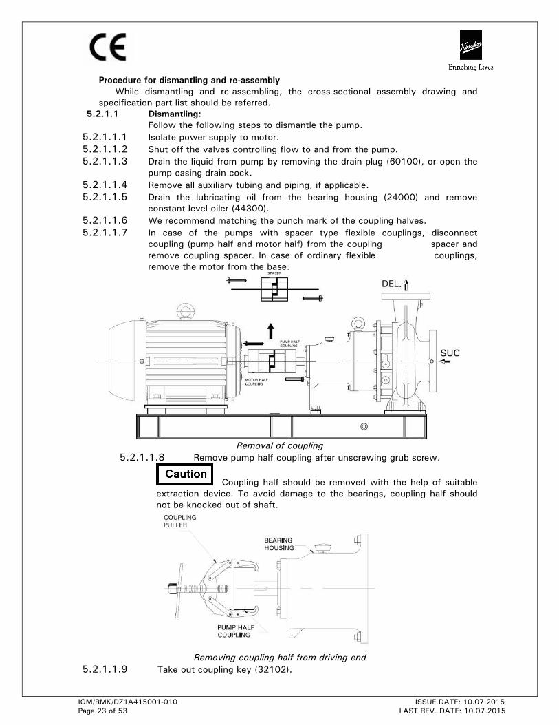
5.2.1.1.7 In case of the pumps with spacer type flexible couplings, disconnect
coupling (pump half and motor half) from the coupling spacer and
remove coupling spacer. In case of ordinary flexible couplings,
remove the motor from the base.
Removal of coupling
5.2.1.1.8 Remove pump half coupling after unscrewing grub screw.
Coupling half should be removed with the help of suitable
extraction device. To avoid damage to the bearings, coupling half should
not be knocked out of shaft.
Removing coupling half from driving end
5.2.1.1.9 Take out coupling key (32102).
IOM/RMK/DZ1A415001-010 ISSUE DATE: 10.07.2015
Page 24 of 53 LAST REV. DATE: 10.07.2015
5.2.1.1.10 Remove the support foot (25100) hold down bolts.
5.2.1.1.11 Remove back pull out assembly (use lifting eye bolt provided for higher
weight pump models).
5.2.1.1.12 In case of casing cover sandwiched between casing and lantern bracket,
remove the hexagonal nuts from casing stud holding the lantern bracket
(24800) to pump casing (10500).
5.2.1.1.13 In case of casing cover is tightened directly to casing (i.e. casing cover is
not sandwiched between casing and lantern bracket), remove the
hexagonal nuts from casing stud holding the casing cover (22000) to
pump casing (10500).
5.2.1.1.14 Screw the release bolts provided in casing cover. Turn bolts evenly
through a quarter turn at both sides.
5.2.1.1.15 Slightly pull out the driving unit till impeller (15100) clears the pump
casing (10500).
5.2.1.1.16 Place this rotating unit on a table or clean and dry place for further
dismantling.
5.2.1.1.17 Remove casing gasket (51101).
5.2.1.1.18 Remove nuts holding Lantern Bracket (24800) and Bearing Housing
(24000). Remove Bearing Housing assembly along with Drive rotor by
pulling out from Lantern Bracket. (Here use Puller to overcome magnet
force. Make use tap provided on pump shaft (18000) to pull out bearing
housing assembly for unit 7 pump models)
5.2.1.1.19 Remove Lantern bracket from casing cover with the help of release
screws.
5.2.1.1.20 Remove Can Cover (23100) and Can (17900) from Casing Cover
5.2.1.1.21 Unscrew the impeller nut (33000 / 33001). Remove the gasket between
impeller and impeller nut (68201).
5.2.1.1.22 Take out the impeller (15100) from impeller shaft (18600). Remove the
washer (84901) between impeller and impeller shaft.
5.2.1.1.23 Carefully remove Thrust bearing carrier assembly of impeller side and from
opposite side take out Impeller shaft along with Impeller rotor assembly,
inner bearing sleeve assembly and Thrust bearing carrier assembly.
Separate out Impeller rotor, Thrust bearing carrier of Impeller rotor side
and impeller shaft.
5.2.1.1.24 Remove Outer bearing sleeve assembly along with bearing holder which is
screwed to casing cover.
5.2.1.1.25 Remove keys of Impeller shaft. This completes dismantling of Wet end
inner impeller magnet assembly.
5.2.1.1.26 Now from dry end, take out Drive rotor (16906) by removing circlip
provided on pump shaft (18000).
IOM/RMK/DZ1A415001-010 ISSUE DATE: 10.07.2015
Page 25 of 53 LAST REV. DATE: 10.07.2015
5.2.1.1.27 Remove bearing cover (along with oil seal) of Driving end side. (For unit 7
remove bearing cover from Non driving end side also)
5.2.1.1.28 Remove Pump shaft along with bearings from bearing housing by pressing
towards coupling side.
5.2.1.1.29 Take out the bearings (26000) from pump shaft with the
help of puller or pressing shaft on arbour press with uniform pressure in
case of only if bearings are damaged and to be replaced.
5.2.1.1.30 Oil seals in the DE & NDE bearing cover (50001/50002) and in the bearing
housing should be removed if the oil seal lips are worn out or spring has
lost tension.
5.2.1.1.31 Casing ring suction side (19000), casing ring delivery side (19100) are to
be removed only, if they are worn out and need replacement.
5.2.1.2 RE-ASSEMBLY :
This procedure covers re-assembly of pump after complete dismantling of
the pump. Before re-assembly, all the parts should be thoroughly cleaned
in kerosene, petrol or benzene to remove the dust, rust etc. After cleaning
the necessary parts should be replaced. Refer Chart of tightening torques
at respective location nut, screws.
5.2.1.2.1 In case bearings are removed, mount the new ball bearings (26000) at
Driving end & Non driving end
a) Use arbour press while fitting the bearings. However it is recommended
that bearings should be heated in oil bath at temperature 70 to 800C and
then fitted. (If hot oil bath is not available then ARBOUR PRESS must be
used).
Use gloves while fitting bearings from hot oil bath.
b) Slide inboard bearing on shaft by hand; make sure that it is square with
shaft. Press evenly the inner race of the bearing until bearing is seated
firmly against the shaft shoulder.
c) Don’t use hammer to fit the bearings. Do not damage the shaft surface
especially where it is in contact with oil seal.
5.2.1.2.2 Fit Oil seal into the bearing housing in case of unit 5. (In case of
replacement if they are removed / damaged.)
5.2.1.2.3 Insert shaft (18000) along with bearings in to the bearing housing from
driving end.
5.2.1.2.4 Replace oil seals in bearing cover (27000) if they are removed / damaged.
5.2.1.2.5 Put gasket (51400) of bearing cover and tighten bearing cover with the aid
of hexagonal headed screws / Cap screws.
5.2.1.2.6 Place gasket (51301) on bearing housing (24000). Lubricate gasket with
grease.
5.2.1.2.7 Put Drive rotor (169D1) fitted with magnet assembly on to the shaft and
insert external circlip (48600).
IOM/RMK/DZ1A415001-010 ISSUE DATE: 10.07.2015
Page 26 of 53 LAST REV. DATE: 10.07.2015
This completes dry end assembly.
5.2.1.2.8 Take Impeller shaft (18600). Insert keys on impeller shaft.
5.2.1.2.9 Slide impeller rotor assembly on to the shaft and rest on step provided of
shaft.
5.2.1.2.10 Slide Thrust bearing carrier assembly (247S1) of impeller rotor side & Inner
bearing sleeve assembly (311S1) on to the shaft. Make sure sleeve is
resting on face of Impeller rotor hub. There is no gap. Also sleeve is not
protruding outside from second step of shaft.
5.2.1.2.11 Take casing cover (22000). Insert outer bearing sleeve assembly (311S2)
and tighten it with the help of bearing holder (25400). Make use of
locating grub screw to make sure lubricating grooves of bearings are
always in horizontal position.
5.2.1.2.12 Insert impeller shaft assembly made in step 5.2.1.2.11 into the casing
cover assembly made in step 5.2.1.2.12 from bearing housing side. Slide
thrust bearing carrier assembly (247S1) of impeller side on to this
assembly.
5.2.1.2.13 Insert washer (84901).
5.2.1.2.14 Push impeller (15100) on shaft till it touches the washer.
5.2.1.2.15 Fix the impeller nut (33000) along with helicoil insert (47900) and
gradually tighten it.
5.2.1.2.16 Place Can (17900) on casing cover putting in between gasket (51201) &
fix Can cover (23100) on can the help of grub screws.
5.2.1.2.17 Rotate impeller and check there is no any abnormal sound present.
5.2.1.2.18 Take pump casing (10500) and put gasket (51101). Lubricate gasket with
grease.
5.2.1.2.19 Insert completed casing cover assembly into the casing guide.
5.2.1.2.20 Mount lantern bracket (24800) on the casing cover guide putting in-
between gasket (51302). Tighten all the nuts on casing studs firmly and
evenly.
This will complete wet end assembly.
5.2.1.2.21 Now slide dry end assembly on to the wet end assembly. Please note,
because of magnetic forces between inner and outer magnets, there will
be sudden jerk hence make use of crane to slide smoothly drive end
assembly on wet end assembly. Tighten all the nuts on lantern bracket
studs firmly and evenly.
5.2.1.2.19 Fit constant level oiler (44300), Breather cap (44400) & support foot
(25100) to bearing housing.
5.2.1.2.20 Rotate shaft by hand and ensure free rotation.
5.2.1.2.21 Fit pump half coupling.
5.2.1.2.22 Fit all applicable accessories such as sealing and flushing liquid, casing
drain piping etc.
5.2.1.2.23 Fit coupling spacer between pump half and motor half coupling in case of
spacer type flexible couplings.
5.2.1.2.24 Mount motor on the base in case of standard flexible coupling and align
the unit.
5.2.1.2.25 Fit coupling guard.
IOM/RMK/DZ1A415001-010 ISSUE DATE: 10.07.2015
Page 27 of 53 LAST REV. DATE: 10.07.2015
SPECIAL IMPORTANT INSTRUCTIONS
1) The instructions given in this book are of general nature. This manual is to be read in contest with C/S (cross-sectional) drawing supplied against order.
2) This drawing should be referred while commissioning of pumps and carrying out any maintenance work.
3) Impeller nut (33000) together with helicoil mid grip insert should be treated as one part only. Please do not try to take out helicoil mid grip insert out of impeller nut. If
helicoil mid grip insert is damaged, please replace impeller nut by new one. Spare
impeller nut is always supplied with helicoil mid grip insert duly fitted in it.
4) Inner bearing sleeve assembly, Outer bearing sleeve assembly, Thrust bearing sleeve assembly, Drive rotor assembly, Impeller rotor assembly sketches are attached at
end of this manual. These should be treated as separate subassemblies. In case of
found damage of any of above, same should be replaced as individual subassembly
only.
• Maintenance tools required:
Make use of Non-Magnetic tools for dismantling and reassembling to avoid injury as
far as possible. Keep at safe distance all tooling after use. Toolbox containing a
general set of tools such as different size ring spanners, torque wrenches, open
ended spanners, light ball peen hammer, wooden mallet, various sizes Allen keys etc
serves the purpose. It is important to ensure that the suitable lifting equipment is
available and that the work is carried out in clean area.
5.3 PREVENTIVE MAINTENANCE:
Preventive maintenance schedule is the periodical checks and precautions by which
possibilities of failures and breakdowns are minimized.
5.3.1 Daily checks:
5.3.1.1 Hourly record of suction and delivery pressure, discharge quantity input to the
pump driver should be maintained.
5.3.1.2 Bearing temperature, oil level, lantern bracket leakage, sealing / lubricating water
inlet and outlet temperature if applicable should be checked. This gives an idea of
mechanical performance of the pump.
5.3.1.3 Noise and vibrations are the first signs of impending troubles like cavitations, air
lock, bearing failure, choking of impeller or casing and such other operating
troubles. The pump performance should therefore be checked for noise and
vibrations.
5.3.2 Periodical checks:
5.3.2.1 The temperature of the bearing should be measured by thermometer. Safe
maximum working temperature of the bearing is 80°C.
5.3.2.2 The lubricants of the bearing should be checked. The lubricant might get
contaminated with foreign material or get blackened due to overheating. In such
cases, bearings should be flushed and charged with fresh lubricants.
5.3.2.3 Check for the Lantern Bracket leakage.
5.3.2.4 The alignment of the pump unit should be checked. Due to operational vibrations,
atmospheric temperature or stress induced by the weight of the piping, the
alignment may get disturbed.
5.3.2.5 Sufficient quantity of suitable type of lubricant should be ready for daily and
emergency use.
IOM/RMK/DZ1A415001-010 ISSUE DATE: 10.07.2015
Page 28 of 53 LAST REV. DATE: 10.07.2015
5.3.2.6 Calibrate the measuring instrument.
5.3.3 Annual checks:
5.3.3.1 The pump should be overhauled completely to check the clearance and to replace
worn-out parts. Clearance between impeller wear rings and casing wear rings are
very important. The bearings should be cleaned thoroughly and lubricated.
5.3.3.2 The effects of liquid handled on pump components should be checked. If abnormal
corrosion, erosion is observed, the component should be replaced with that of
suitable material.
5.3.3.3 The auxiliary pipelines and functioning of the auxiliary system should be checked.
The main pipe also should be checked for scaling, leakage etc.
5.3.3.4 The measuring instruments, gauges etc should be recalibrated.
5.3.3.5 Full running test may be carried out to check whether there is any fault in the
performance, in comparison with original performance.
5.3.3.6 Piping supports should be checked so that the pipes do not induce unwanted
stresses on the pump.
5.3.4: SSiC Bearing assemblies in pump:
SSiC bearing assemblies are precision product having been subjected to quality
control throughout all stages of manufacture. The bearings are designed to
accommodate reasonable tolerances in the equipment, however in order to obtain
the maximum life with trouble free performance, the equipment should be
adequately maintained.
When bearings are functioning satisfactorily, the preventive maintenance is not
advocated. While fitting the bearing subassemblies in the pump initially by KBL, due
care is taken for its proper fitment.
Like other parts in the equipment the bearings are subject to wear at the mating
faces of the rotating and stationary bushes. The rate of wear will differ with the
operating conditions and various other factors such as lubricating property of the
liquid pumped, the presence of impurities in liquid and other operating conditions. In
view of this no firm recommendations can be given for renewal of individual
subassemblies / complete subassemblies.
External Lubrication / flushing: The bearings are not designed to run in dry condition.
Hence in case of external lubrication do no run the pumps without first starting
external lubrication / flushing into the casing cover. Please refer pump cross section
drawing and general arrangement drawing for flushing connection details, pressure
and temperature details.
5.4 CORRECTIVE MAINTENANCE
PUMP TROUBLE
When investigating trouble with Kirloskar pumps, always remember that pumps
have been tested at the factory and are mechanically correct when sent out.
Discounting the possibility of damage during transit, most of the trouble in the field
is due to faulty installation. Investigation shows that the majority of troubles with
centrifugal pumps result from faulty conditions on the suction side.
BREAK DOWN-CAUSE-CHECK POINTS
In case of breakdown we recommend the location of the fault by referring the table
for ‘Break Down Check Points’ given at the end of this manual.
IOM/RMK/DZ1A415001-010 ISSUE DATE: 10.07.2015
Page 29 of 53 LAST REV. DATE: 10.07.2015
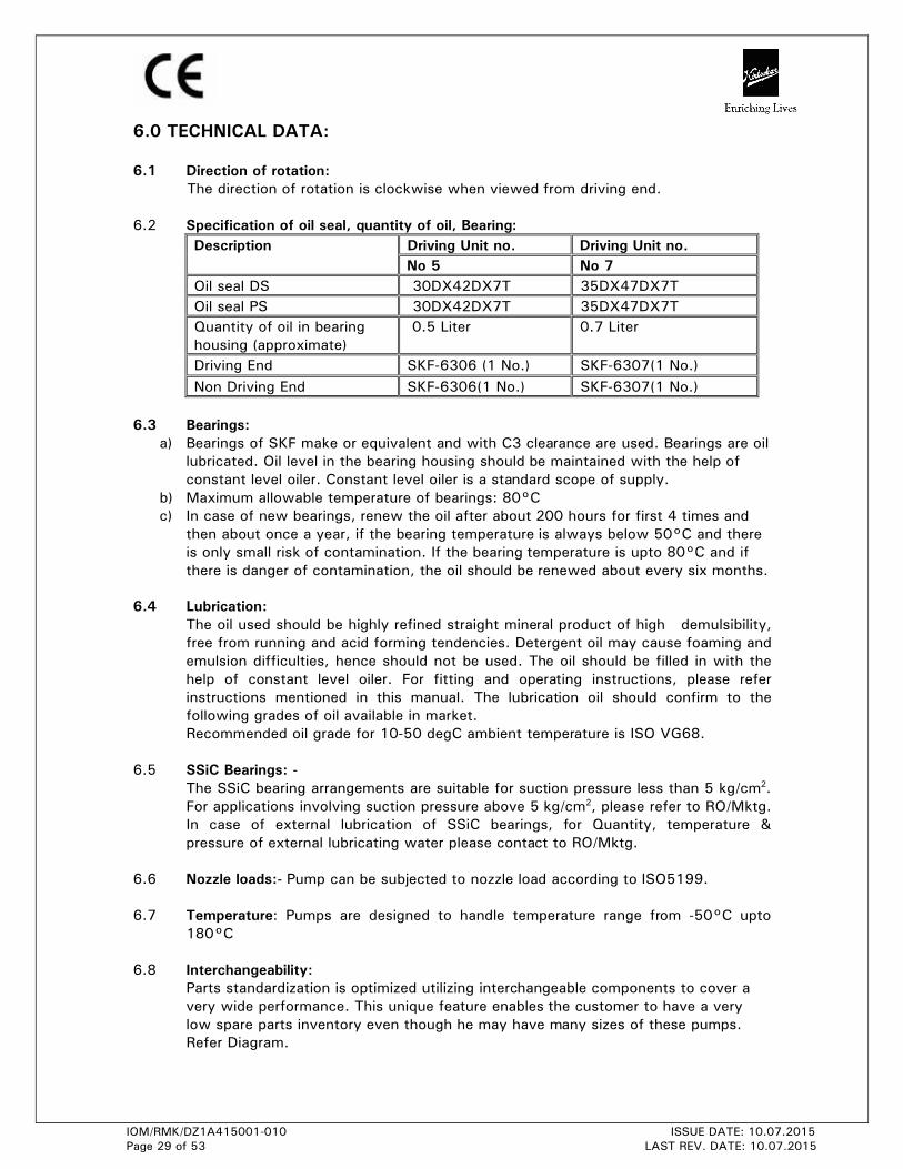
6.0 TECHNICAL DATA: 6.1 Direction of rotation:
The direction of rotation is clockwise when viewed from driving end.
6.2 Specification of oil seal, quantity of oil, Bearing:
Description Driving Unit no. Driving Unit no. No 5 No 7
Oil seal DS 30DX42DX7T 35DX47DX7T
Oil seal PS 30DX42DX7T 35DX47DX7T
Quantity of oil in bearing
housing (approximate)
0.5 Liter 0.7 Liter
Driving End SKF-6306 (1 No.) SKF-6307(1 No.)
Non Driving End SKF-6306(1 No.) SKF-6307(1 No.)
6.3 Bearings:
a) Bearings of SKF make or equivalent and with C3 clearance are used. Bearings are oil lubricated. Oil level in the bearing housing should be maintained with the help of
constant level oiler. Constant level oiler is a standard scope of supply.
b) Maximum allowable temperature of bearings: 80°C c) In case of new bearings, renew the oil after about 200 hours for first 4 times and
then about once a year, if the bearing temperature is always below 50°C and there
is only small risk of contamination. If the bearing temperature is upto 80°C and if
there is danger of contamination, the oil should be renewed about every six months.
6.4 Lubrication:
The oil used should be highly refined straight mineral product of high demulsibility,
free from running and acid forming tendencies. Detergent oil may cause foaming and
emulsion difficulties, hence should not be used. The oil should be filled in with the
help of constant level oiler. For fitting and operating instructions, please refer
instructions mentioned in this manual. The lubrication oil should confirm to the
following grades of oil available in market.
Recommended oil grade for 10-50 degC ambient temperature is ISO VG68.
6.5 SSiC Bearings: -
The SSiC bearing arrangements are suitable for suction pressure less than 5 kg/cm2.
For applications involving suction pressure above 5 kg/cm2, please refer to RO/Mktg.
In case of external lubrication of SSiC bearings, for Quantity, temperature &
pressure of external lubricating water please contact to RO/Mktg.
6.6 Nozzle loads:- Pump can be subjected to nozzle load according to ISO5199.
6.7 Temperature: Pumps are designed to handle temperature range from -50°C upto
180°C
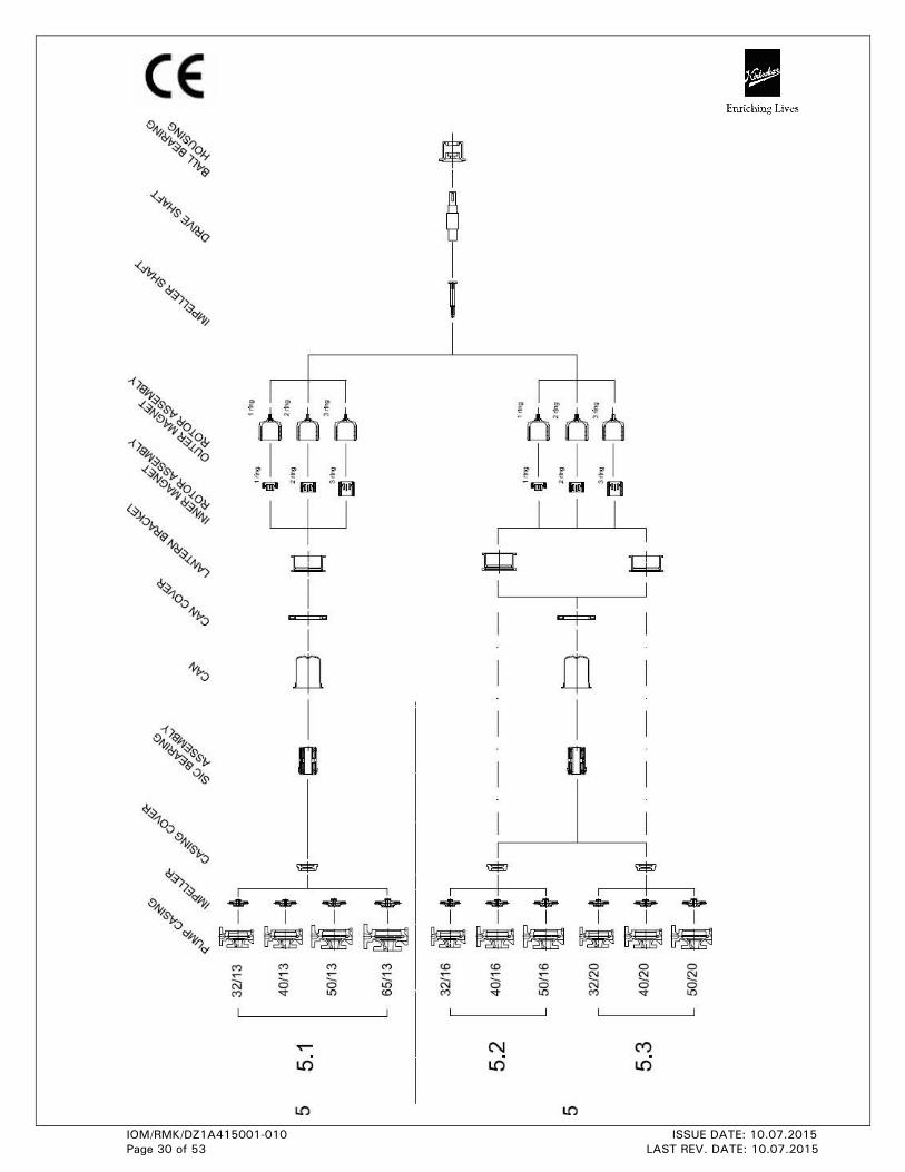
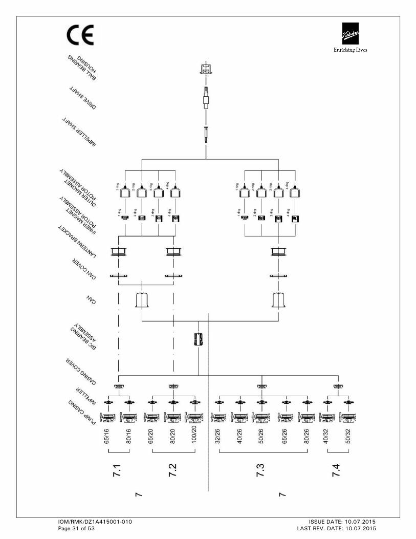
6.8 Interchangeability:
Parts standardization is optimized utilizing interchangeable components to cover a
very wide performance. This unique feature enables the customer to have a very
low spare parts inventory even though he may have many sizes of these pumps.
Refer Diagram.
IOM/RMK/DZ1A415001-010 ISSUE DATE: 10.07.2015
Page 30 of 53 LAST REV. DATE: 10.07.2015
IOM/RMK/DZ1A415001-010 ISSUE DATE: 10.07.2015
Page 31 of 53 LAST REV. DATE: 10.07.2015
IOM/RMK/DZ1A415001-010 ISSUE DATE: 10.07.2015
Page 32 of 53 LAST REV. DATE: 10.07.2015
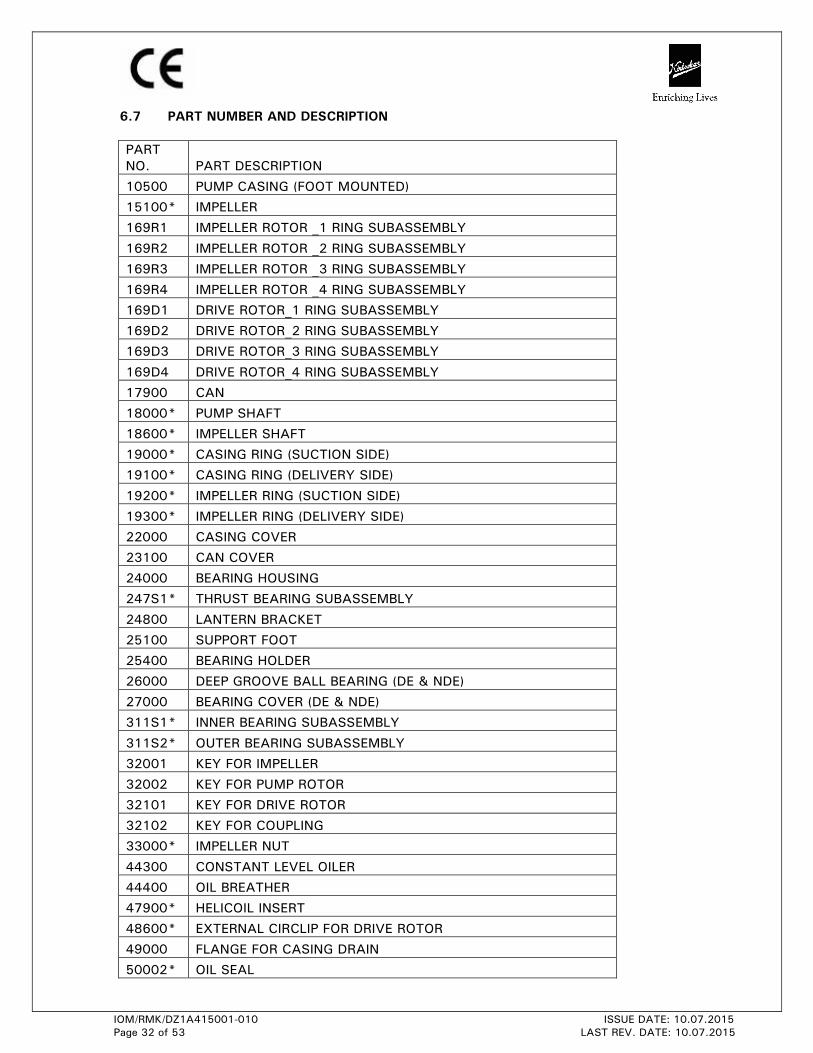
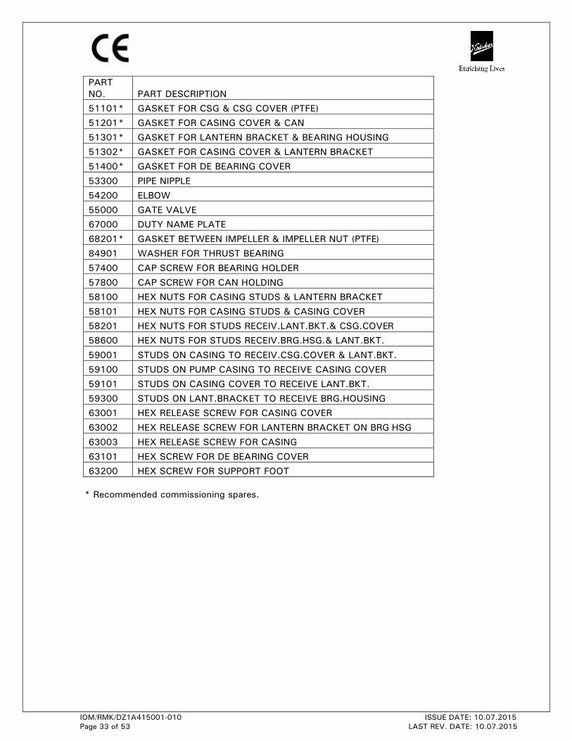
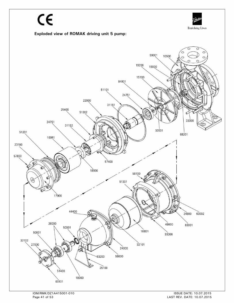
6.7 PART NUMBER AND DESCRIPTION
PART
NO. PART DESCRIPTION
10500 PUMP CASING (FOOT MOUNTED)
15100* IMPELLER
169R1 IMPELLER ROTOR _1 RING SUBASSEMBLY
169R2 IMPELLER ROTOR _2 RING SUBASSEMBLY
169R3 IMPELLER ROTOR _3 RING SUBASSEMBLY
169R4 IMPELLER ROTOR _4 RING SUBASSEMBLY
169D1 DRIVE ROTOR_1 RING SUBASSEMBLY
169D2 DRIVE ROTOR_2 RING SUBASSEMBLY
169D3 DRIVE ROTOR_3 RING SUBASSEMBLY
169D4 DRIVE ROTOR_4 RING SUBASSEMBLY
17900 CAN
18000* PUMP SHAFT
18600* IMPELLER SHAFT
19000* CASING RING (SUCTION SIDE)
19100* CASING RING (DELIVERY SIDE)
19200* IMPELLER RING (SUCTION SIDE)
19300* IMPELLER RING (DELIVERY SIDE)
22000 CASING COVER
23100 CAN COVER
24000 BEARING HOUSING
247S1* THRUST BEARING SUBASSEMBLY
24800 LANTERN BRACKET
25100 SUPPORT FOOT
25400 BEARING HOLDER
26000 DEEP GROOVE BALL BEARING (DE & NDE)
27000 BEARING COVER (DE & NDE)
311S1* INNER BEARING SUBASSEMBLY
311S2* OUTER BEARING SUBASSEMBLY
32001 KEY FOR IMPELLER
32002 KEY FOR PUMP ROTOR
32101 KEY FOR DRIVE ROTOR
32102 KEY FOR COUPLING
33000* IMPELLER NUT
44300 CONSTANT LEVEL OILER
44400 OIL BREATHER
47900* HELICOIL INSERT
48600* EXTERNAL CIRCLIP FOR DRIVE ROTOR
49000 FLANGE FOR CASING DRAIN
50002* OIL SEAL
IOM/RMK/DZ1A415001-010 ISSUE DATE: 10.07.2015
Page 33 of 53 LAST REV. DATE: 10.07.2015
PART
NO. PART DESCRIPTION
51101* GASKET FOR CSG & CSG COVER (PTFE)
51201* GASKET FOR CASING COVER & CAN
51301* GASKET FOR LANTERN BRACKET & BEARING HOUSING
51302* GASKET FOR CASING COVER & LANTERN BRACKET
51400* GASKET FOR DE BEARING COVER
53300 PIPE NIPPLE
54200 ELBOW
55000 GATE VALVE
67000 DUTY NAME PLATE
68201* GASKET BETWEEN IMPELLER & IMPELLER NUT (PTFE)
84901 WASHER FOR THRUST BEARING
57400 CAP SCREW FOR BEARING HOLDER
57800 CAP SCREW FOR CAN HOLDING
58100 HEX NUTS FOR CASING STUDS & LANTERN BRACKET
58101 HEX NUTS FOR CASING STUDS & CASING COVER
58201 HEX NUTS FOR STUDS RECEIV.LANT.BKT.& CSG.COVER
58600 HEX NUTS FOR STUDS RECEIV.BRG.HSG.& LANT.BKT.
59001 STUDS ON CASING TO RECEIV.CSG.COVER & LANT.BKT.
59100 STUDS ON PUMP CASING TO RECEIVE CASING COVER
59101 STUDS ON CASING COVER TO RECEIVE LANT.BKT.
59300 STUDS ON LANT.BRACKET TO RECEIVE BRG.HOUSING
63001 HEX RELEASE SCREW FOR CASING COVER
63002 HEX RELEASE SCREW FOR LANTERN BRACKET ON BRG HSG
63003 HEX RELEASE SCREW FOR CASING
63101 HEX SCREW FOR DE BEARING COVER
63200 HEX SCREW FOR SUPPORT FOOT
* Recommended commissioning spares.
IOM/RMK/DZ1A415001-010 ISSUE DATE: 10.07.2015
Page 34 of 53 LAST REV. DATE: 10.07.2015
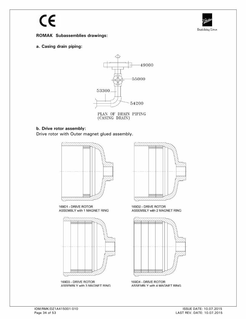
ROMAK Subassemblies drawings:
a. Casing drain piping:
b. Drive rotor assembly:
Drive rotor with Outer magnet glued assembly.
IOM/RMK/DZ1A415001-010 ISSUE DATE: 10.07.2015
Page 35 of 53 LAST REV. DATE: 10.07.2015
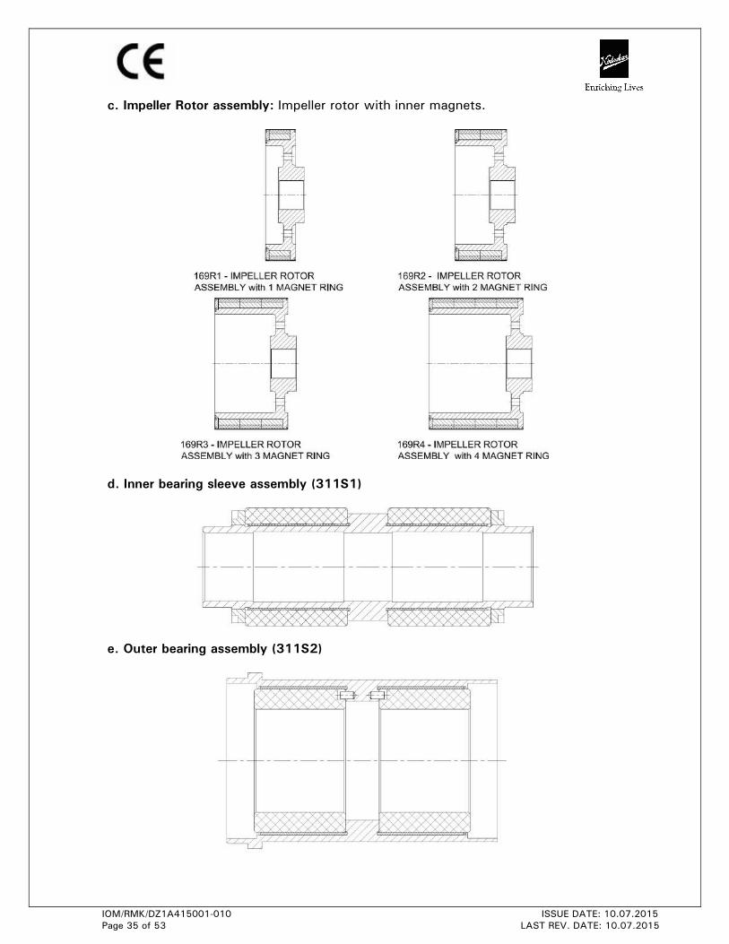
c. Impeller Rotor assembly: Impeller rotor with inner magnets.
d. Inner bearing sleeve assembly (311S1)
e. Outer bearing assembly (311S2)
IOM/RMK/DZ1A415001-010 ISSUE DATE: 10.07.2015
Page 36 of 53 LAST REV. DATE: 10.07.2015
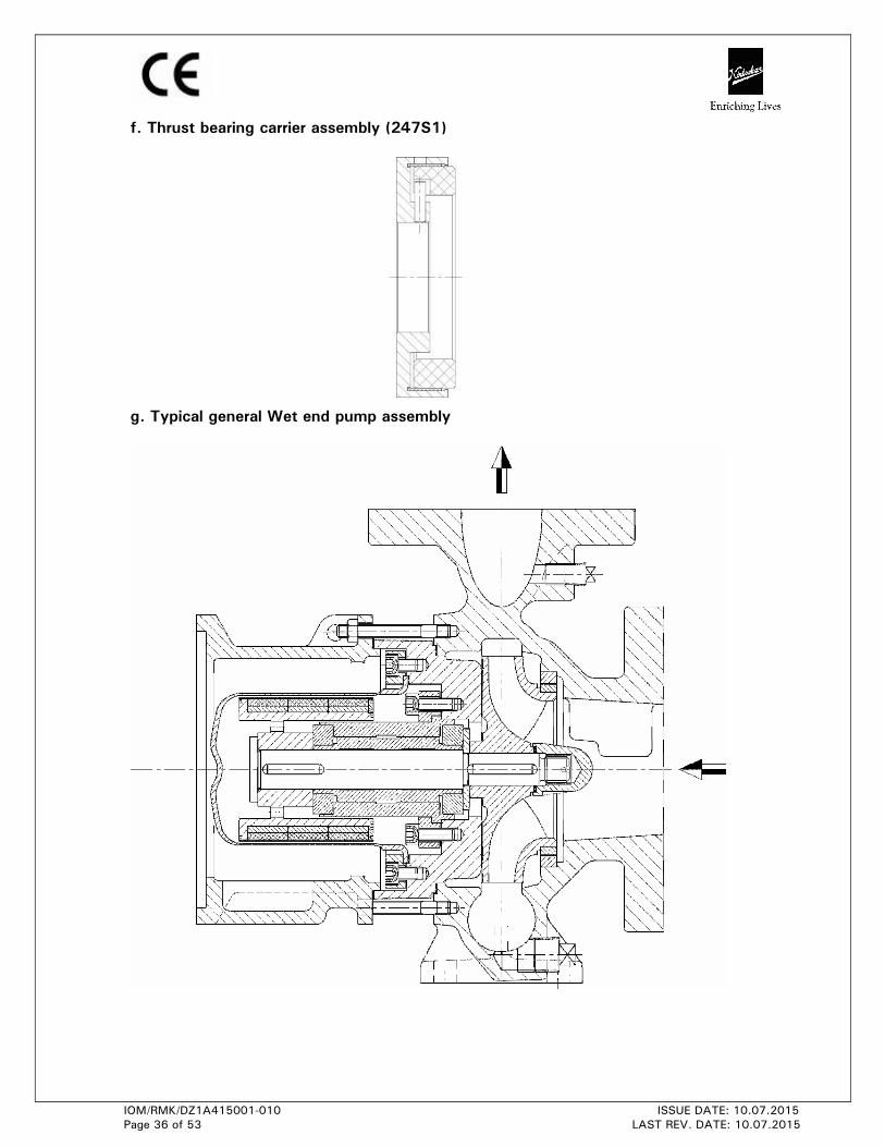
f. Thrust bearing carrier assembly (247S1)
g. Typical general Wet end pump assembly
IOM/RMK/DZ1A415001-010 ISSUE DATE: 10.07.2015
Page 37 of 53 LAST REV. DATE: 10.07.2015
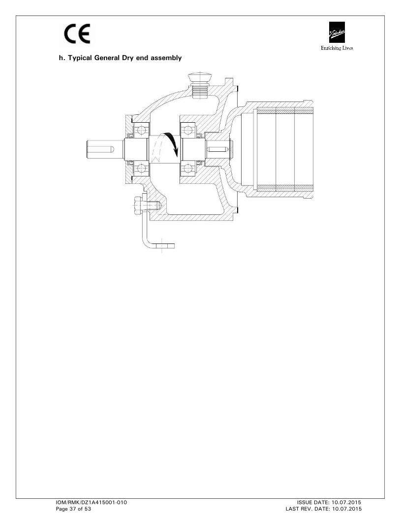
h. Typical General Dry end assembly
IOM/RMK/DZ1A415001-010 ISSUE DATE: 10.07.2015
Page 38 of 53 LAST REV. DATE: 10.07.2015
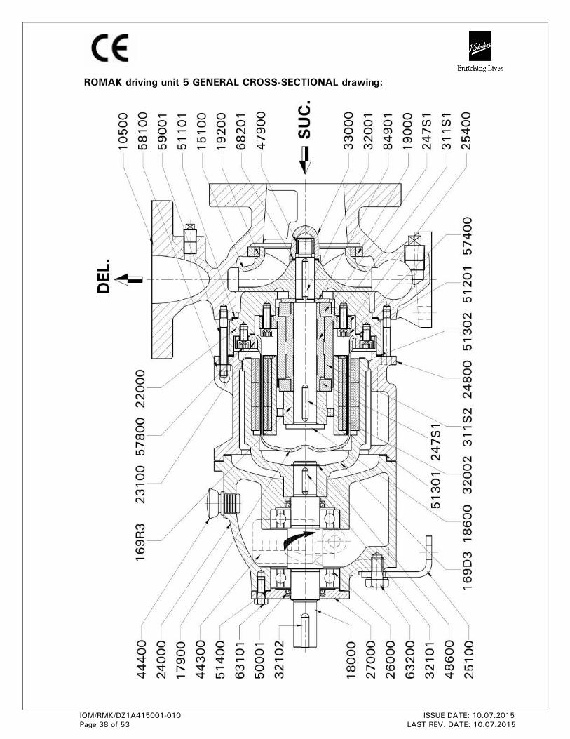
ROMAK driving unit 5 GENERAL CROSS-SECTIONAL drawing:
IOM/RMK/DZ1A415001-010 ISSUE DATE: 10.07.2015
Page 39 of 53 LAST REV. DATE: 10.07.2015
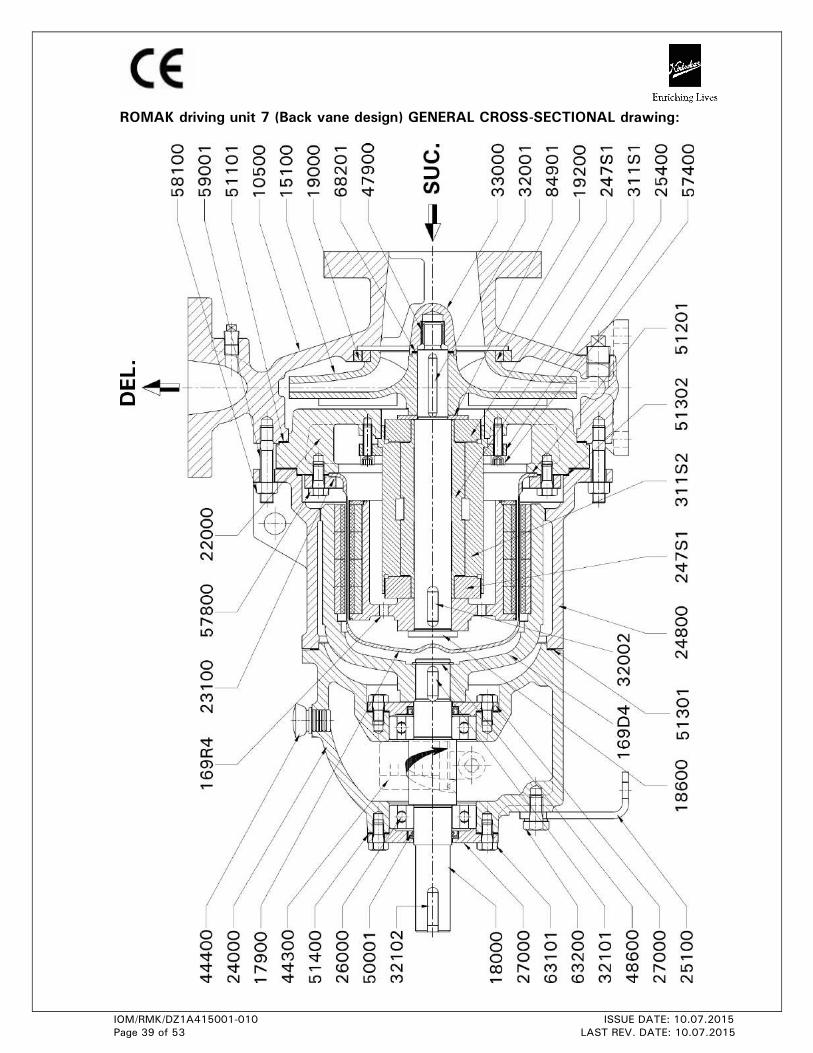
ROMAK driving unit 7 (Back vane design) GENERAL CROSS-SECTIONAL drawing:
IOM/RMK/DZ1A415001-010 ISSUE DATE: 10.07.2015
Page 40 of 53 LAST REV. DATE: 10.07.2015
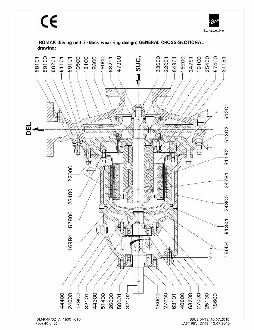
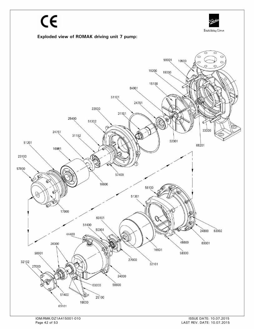
ROMAK driving unit 7 (Back wear ring design) GENERAL CROSS-SECTIONAL
drawing:
IOM/RMK/DZ1A415001-010 ISSUE DATE: 10.07.2015
Page 41 of 53 LAST REV. DATE: 10.07.2015
Exploded view of ROMAK driving unit 5 pump:
IOM/RMK/DZ1A415001-010 ISSUE DATE: 10.07.2015
Page 42 of 53 LAST REV. DATE: 10.07.2015
Exploded view of ROMAK driving unit 7 pump:
IOM/RMK/DZ1A415001-010 ISSUE DATE: 10.07.2015
Page 43 of 53 LAST REV. DATE: 10.07.2015
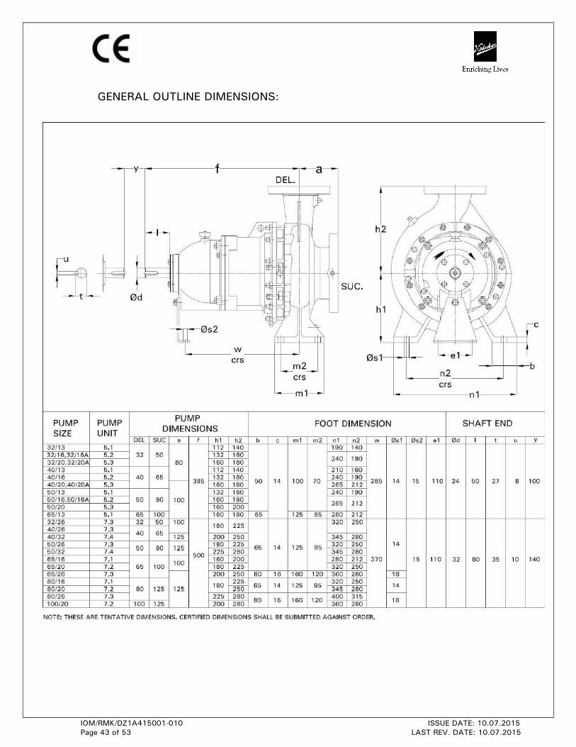
GENERAL OUTLINE DIMENSIONS:
IOM/RMK/DZ1A415001-010 ISSUE DATE: 10.07.2015
Page 44 of 53 LAST REV. DATE: 10.07.2015
GENERAL INFORMATION & SAFETY INSTRUCTIONS
1.0 The products supplied by KBL have been designed with safety in mind. Where
hazards cannot be eliminated, the risk has been minimized by the use of guards
and other design features. Some hazards cannot be guarded against and the
instructions below MUST BE COMPLIED WITH for safe operation. These
instructions cannot cover all circumstances. Installation, operation and
maintenance personnel must use safe working practices at all the times.
1.1 KBL products are designed for installation in designated areas, which are to be
kept clean and free of obstructions that may restrict safe access to the controls
and maintenance access points.
A pump duty nameplate is fitted to each unit and must not be removed. Loss of
this plate could make identification impossible. This in turn could affect safety and
cause difficulty in obtaining spare parts. If accidental loss or damage occurs,
contact KBL immediately.
1.2 Access to the equipment should be restricted to the person net responsible for
installation, operation and maintenance and they must be trained, adequately
qualified and supplied with appropriate tools for their respective tasks.
1.3 Most accidents involving product operation, maintenance and repair are caused by
failure to observe safety rules or precautions. An accident can often be avoided by
recognizing potentially situations before an accident occurs. A person must be
aware of potential hazard associated in activities of installation, operation and
maintenance of equipments.
1.4 KBL requires that, all personnel that are responsible for installation, operation or
maintenance of the equipment, have access to and study the product instruction
manual BEFORE any work is done and that they will comply with all local and
industry based safety instructions and regulations.
1.5 Ear defenders should be worn where the specified equipment noise level exceeds
locally defined safe levels. Safety glasses or goggles or face shield should be worn
where working with pressurized systems and hazardous substances. Other
personal protection equipment must be worn where local rules apply. Wear safety
shoes, helmets and cotton overall [Apron] when you enter pump house. Noise
level should not exceed 90 dbA and 110 dbA for motor driven and engine driven
pumps, respectively.
1.6 Do not wear loose clothing or jewelry, which could catch on the controls or
become trapped in the equipment.
1.7 Read the instruction manual before installation, operation or maintenance of the
equipment. Check and confirm that you are referring relevant copy of the manual
by comparing pump type on the nameplate and with that on the manual.
1.8 Note the “Limits of product application permissible use” specified in the manual.
Operation of the equipment beyond these limits will increase the risk from hazards
noted below and may lead to premature and hazardous pump failure.
IOM/RMK/DZ1A415001-010 ISSUE DATE: 10.07.2015
Page 45 of 53 LAST REV. DATE: 10.07.2015
1.9 Clear and easy access to all controls, gauges and dials etc must be maintained at
all times. Hazardous or flammable materials must not be stored in pump rooms
unless safe areas or racking and suitable container have been provided.
1.10 Use suitable earthing and tripping devices for electrical equipments.
2. IMPROPER INSTALLATION, OPERATION, MAINTENANCE, LUBRICATION, REPAIR OF
THIS KBL PRODUCT COULD RESULT IN INJURY OR DEATH.
If any tool, procedure, work method and operation technique is not recommended by
KIRLOSKAR BROTHERS LIMITED is used or followed, it should be ensured that it is a
safe for personnel around and others. It should also be ensured that the product will
not be damaged or made unsafe by the operation, lubrication and maintenance or
repair procedures you choose.
3. SAFETY INSTRUCTIONS WHILE HANDLING AND STORAGE
When lifting the pump, use the lifting points specified on general arrangement
drawing, if provided. Use lifting equipment having a safe working load rating suitable
for the weight specified. Use suitable slings for lifting pump, which is not provided,
with lifting points. The use of forklift truck and chain crane sling equipment is
recommended but locally approved equipment of suitable rating may be used. While
lifting, the equipment adjusts the center of gravity, so that it is balanced properly.
Do not place fingers or hands etc into the suction or discharge pipe outlets and do not
touch the impeller, if rotated this may cause severe injury. To prevent ingress of any
objects, retain the protection covers or packaging in place until removal is necessary
for installation. If the packaging or suction and discharge covers are removed for
inspection purposes, replace afterwards to protect the pump and maintain safety.
4. SAFETY INSTRUCTIONS WHILE ASSEMBLY & INSTALLATION
Shaft alignment must be checked again after the final positioning of the pump unit and
connection to pipework as this may have disturbed the pump or motor mounting
positions. If hot liquids [above 80°C] are being pumped, alignment should be checked
and reset with the pump and motor at their normal operating temperature. If this is not
possible, KBL can supply estimated initial offset figures to suit extreme operating
temperatures.
Failure to support suction and delivery pipework may result in distortion of the pump
casing, with the possibility of early pump failure.
5. SAFETY INSTRUCTIONS WHILE COMMISSIONING & OPERATION
Never attempt adjustments while the pump is running, unless otherwise specified in
the operation, maintenance manual.
Do not touch any moving or rotating parts. Guards are provided to prevent access to
these parts, where they have been removed for maintenance they must be replaced
before operating the equipment.
Check that pump is primed. Pump should never be run dry as the pumped liquid acts
as lubricant for the close running fits surrounding impeller and damage will be
incurred.
Failure to supply the stuffing box or mechanical seal with cooling of flush water may
result in damage and premature failure of the pump.
IOM/RMK/DZ1A415001-010 ISSUE DATE: 10.07.2015
Page 46 of 53 LAST REV. DATE: 10.07.2015
Do not touch surfaces, which during normal running will be sufficiently hot to cause
injury. Note that these surfaces remain hot after the pump has stopped, allow
sufficient time for cooling before maintenance. Be cautious and note that other parts
of the pump may become hot if a fault is developing.
Do not operate water pumps in temperatures below freezing point, without first
checking that the pumped fluid is not frozen and the pump is free to turn. Pumps in
these environments should be drained down during inactivity and re-primed before
starting.
In addition to local or site regulations for noise protection, KBL recommend the use of
personal ear protection equipment in all enclosed pump rooms and particularly those
containing diesel engines. Care must be taken to ensure that any audible alarm or
warning signal can be heard with car defenders worn.
Be aware of the hazards relating to the pump fluid, especially the danger from
inhalation of noxious and toxic gases, skin and eye contact or penetration. Obtain and
understand the hazardous substance data sheets relating to the pumped fluid and note
the recommended emergency and first aid procedures.
6. SAFETY INSTRUCTIONS WHILE MAINTENANCE & SERVICING
Do not attempt repairs of the pump or its accessories which you do not know. Use
proper tools.
Before attempting any maintenance on a pump particularly if it has been handling any
form of hazardous liquid, it should be ensured that the unit is safe to work on. The
pump must be flushed thoroughly with suitable cleaner to purge away any of the
product left in the pump components.
This should be carried out by the plant operator and a certificate of cleanliness
obtained before starting work. To avoid any risk to health it is also advisable to wear
protective clothing as recommended by the site safety officer especially when
removing old packing, which may be contaminated.
Isolate the equipment before any maintenance work is done. Switch off the main
supply, remove fuses, apply lockouts where applicable and affix suitable isolation
warning signs to prevent inadvertent reconnection. In order to avoid the possibility of
maintenance personnel inhaling dangerous fumes or vapours locations by removal of
bearing housing and shaft assembly to a suitable maintenance area.
Check and ensure that the pump operates at below the maximum working pressure
specified in the manual or on the pump namepate and before maintenance, ensure that
the pump is drained down.
Wear a suitable mask or respirator when working with packing and gasket contain
fibrous material, as these can be hazardous when the fibrous dust is inhaled. Be
cautious, if other supplier’s components have been substituted for genuine KBL parts,
these may then contain hazardous materials.
Store all oily rags or other flammable material in a protective container in a safe place.
Do not weld or flame cut on pipes/tubes that contents flammable fluids. Clean them
thoroughly with nonflammable solvent before welding or flame cutting on them. Use
solvent/chemical resistant gloves for hand protection.
Dispose of all wastes like gaskets, gland packing, oil, batteries, packing material etc in
accordance with local regulations. Normally this would involve incineration of liquid
waste and controlled landfill of polymerized material.
Adequacy of suitable crane should be checked before lifting the pump/pump
components. Also condition of pulleys, chain and lifting shackles should be checked
before use.
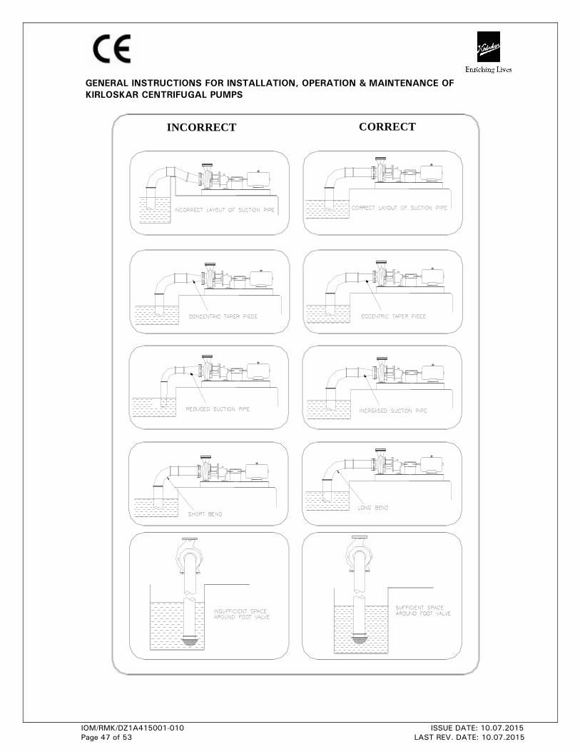
IOM/RMK/DZ1A415001-010 ISSUE DATE: 10.07.2015
Page 47 of 53 LAST REV. DATE: 10.07.2015
CORRECTINCORRECT
GENERAL INSTRUCTIONS FOR INSTALLATION, OPERATION & MAINTENANCE OF
KIRLOSKAR CENTRIFUGAL PUMPS
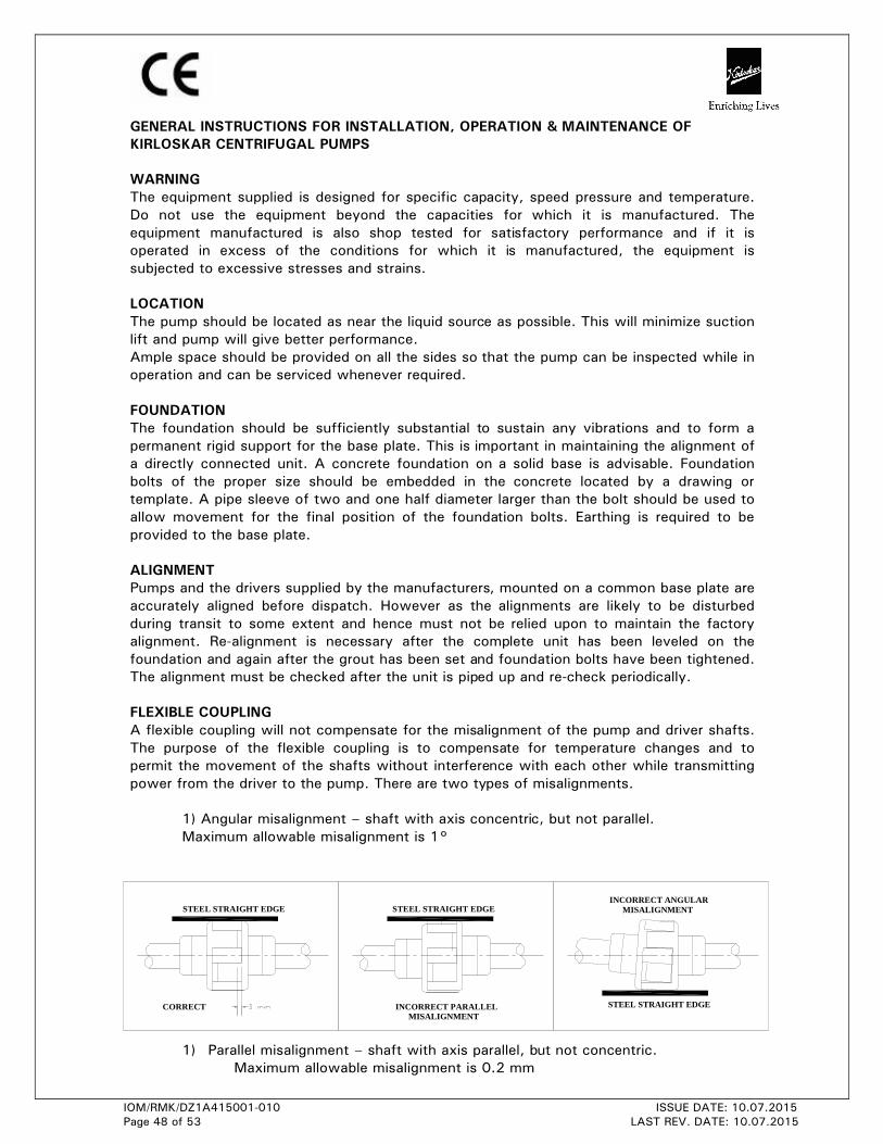
IOM/RMK/DZ1A415001-010 ISSUE DATE: 10.07.2015
Page 48 of 53 LAST REV. DATE: 10.07.2015
CORRECT
STEEL STRAIGHT EDGE
INCORRECT PARALLEL MISALIGNMENT
STEEL STRAIGHT EDGE
STEEL STRAIGHT EDGE
INCORRECT ANGULAR MISALIGNMENT
GENERAL INSTRUCTIONS FOR INSTALLATION, OPERATION & MAINTENANCE OF
KIRLOSKAR CENTRIFUGAL PUMPS
WARNING
The equipment supplied is designed for specific capacity, speed pressure and temperature.
Do not use the equipment beyond the capacities for which it is manufactured. The
equipment manufactured is also shop tested for satisfactory performance and if it is
operated in excess of the conditions for which it is manufactured, the equipment is
subjected to excessive stresses and strains.
LOCATION
The pump should be located as near the liquid source as possible. This will minimize suction
lift and pump will give better performance.
Ample space should be provided on all the sides so that the pump can be inspected while in
operation and can be serviced whenever required.
FOUNDATION
The foundation should be sufficiently substantial to sustain any vibrations and to form a
permanent rigid support for the base plate. This is important in maintaining the alignment of
a directly connected unit. A concrete foundation on a solid base is advisable. Foundation
bolts of the proper size should be embedded in the concrete located by a drawing or
template. A pipe sleeve of two and one half diameter larger than the bolt should be used to
allow movement for the final position of the foundation bolts. Earthing is required to be
provided to the base plate.
ALIGNMENT
Pumps and the drivers supplied by the manufacturers, mounted on a common base plate are
accurately aligned before dispatch. However as the alignments are likely to be disturbed
during transit to some extent and hence must not be relied upon to maintain the factory
alignment. Re-alignment is necessary after the complete unit has been leveled on the
foundation and again after the grout has been set and foundation bolts have been tightened.
The alignment must be checked after the unit is piped up and re-check periodically.
FLEXIBLE COUPLING
A flexible coupling will not compensate for the misalignment of the pump and driver shafts.
The purpose of the flexible coupling is to compensate for temperature changes and to
permit the movement of the shafts without interference with each other while transmitting
power from the driver to the pump. There are two types of misalignments.
1) Angular misalignment – shaft with axis concentric, but not parallel.
Maximum allowable misalignment is 1°
1) Parallel misalignment – shaft with axis parallel, but not concentric. Maximum allowable misalignment is 0.2 mm
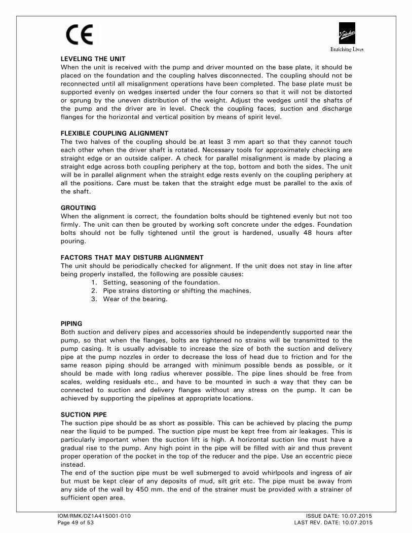
IOM/RMK/DZ1A415001-010 ISSUE DATE: 10.07.2015
Page 49 of 53 LAST REV. DATE: 10.07.2015
LEVELING THE UNIT
When the unit is received with the pump and driver mounted on the base plate, it should be
placed on the foundation and the coupling halves disconnected. The coupling should not be
reconnected until all misalignment operations have been completed. The base plate must be
supported evenly on wedges inserted under the four corners so that it will not be distorted
or sprung by the uneven distribution of the weight. Adjust the wedges until the shafts of
the pump and the driver are in level. Check the coupling faces, suction and discharge
flanges for the horizontal and vertical position by means of spirit level.
FLEXIBLE COUPLING ALIGNMENT
The two halves of the coupling should be at least 3 mm apart so that they cannot touch
each other when the driver shaft is rotated. Necessary tools for approximately checking are
straight edge or an outside caliper. A check for parallel misalignment is made by placing a
straight edge across both coupling periphery at the top, bottom and both the sides. The unit
will be in parallel alignment when the straight edge rests evenly on the coupling periphery at
all the positions. Care must be taken that the straight edge must be parallel to the axis of
the shaft.
GROUTING
When the alignment is correct, the foundation bolts should be tightened evenly but not too
firmly. The unit can then be grouted by working soft concrete under the edges. Foundation
bolts should not be fully tightened until the grout is hardened, usually 48 hours after
pouring.
FACTORS THAT MAY DISTURB ALIGNMENT
The unit should be periodically checked for alignment. If the unit does not stay in line after
being properly installed, the following are possible causes:
1. Setting, seasoning of the foundation. 2. Pipe strains distorting or shifting the machines. 3. Wear of the bearing.
PIPING
Both suction and delivery pipes and accessories should be independently supported near the
pump, so that when the flanges, bolts are tightened no strains will be transmitted to the
pump casing. It is usually advisable to increase the size of both the suction and delivery
pipe at the pump nozzles in order to decrease the loss of head due to friction and for the
same reason piping should be arranged with minimum possible bends as possible, or it
should be made with long radius wherever possible. The pipe lines should be free from
scales, welding residuals etc., and have to be mounted in such a way that they can be
connected to suction and delivery flanges without any stress on the pump. It can be
achieved by supporting the pipelines at appropriate locations.
SUCTION PIPE
The suction pipe should be as short as possible. This can be achieved by placing the pump
near the liquid to be pumped. The suction pipe must be kept free from air leakages. This is
particularly important when the suction lift is high. A horizontal suction line must have a
gradual rise to the pump. Any high point in the pipe will be filled with air and thus prevent
proper operation of the pocket in the top of the reducer and the pipe. Use an eccentric piece
instead.
The end of the suction pipe must be well submerged to avoid whirlpools and ingress of air
but must be kept clear of any deposits of mud, silt grit etc. The pipe must be away from
any side of the wall by 450 mm. the end of the strainer must be provided with a strainer of
sufficient open area.

IOM/RMK/DZ1A415001-010 ISSUE DATE: 10.07.2015
Page 50 of 53 LAST REV. DATE: 10.07.2015
DELIVERY PIPE
A check (non return) valve and a gate of sluice valve (regulating valve) should be installed in
the discharge line. The check valve placed between the pump and the gate valve is to
protect the pump from excessive pressure and to prevent water running back through the
pump in case of failure of the driving machine.
Discharge piping should be provided with a sluice valve adjacent to the delivery flange to
control the discharge if required.
VACUUM EQUALIZING LINE (AND LIQUID LINE)
If the pump draws from a system under vacuum an equalizing pipe must be carried from the
highest point of the suction line, however as close to the suction flange of the pump as
possible, to the top of the feed tank to keep gas bubbles that might have been entrapped in
the flow from entering the pump. The line should be fitted with an isolating valve which
should be closed only for maintenance work on the pumpset.
Apply sealing liquid (external sealing) to the shaft seal cage to prevent entry of air in the
case of the pumps with packed stuffing box. It is convenient to tap the sealing liquid from
the delivery line above the non-return valve.
FOOT-VALVE
It is advisable to install a foot-valve to facilitate priming. The foot-valve should have
sufficient clear passage for water. Care must be taken to prevent foreign matter from being
drawn in to the pump or chocking the foot-valve and for this purpose an efficient strainer
should be provided.
STUFFING BOXES AND PACKING (only for gland packed pump)
Stuffing boxes should be carefully cleaned and packing placed in them. Be sure that
sufficient packing is placed at the back of the water seal cage. If the water to be pumped is
dirty or gritty, sealing water should be piped to the stuffing boxes from clean outside source
of supply in order to prevent damage to the packing and shaft. In placing the packing, each
packing ring should be cut to the proper length so that ends come together but don’t
overlap. The succeeding rings of packing should not be pressed too tight, as it may result in
burning the packing and cutting the shaft. If the stuffing box is not properly packed, friction
in stuffing box prevents turning the rotor by hand. On starting the pump it is well to have
the packing slightly loose without causing an air leak, and if it seems to leak, instead of
putting too much pressure on the gland, put some heavy oil in the stuffing box until the
pump works properly and then gradually tighten up the gland. The packing should be
occasionally changed.
BALL BEARINGS
Correct maintenance of ball bearings is essential. The bearing manufacturers give the
following as a guide to re-lubrication periods under normal condition for Grease lubricated
bearings.
Three monthly when on continuous duty.
Six monthly when on eight hour per day duty.
The bearings and housings should be completely cleaned and recharged with fresh grease
after 2500 hrs. or the nearest pump overhaul time.
PRIMING
No pumping action occurs unless the pump casing is filled with the liquid. Pump casing and
suction pipe must therefore be completely filled with liquid and thus all air removed before
the pump is started. Several different priming methods can be used depending on the kind
of installation and service involved.
1) Liquid level above pump level.
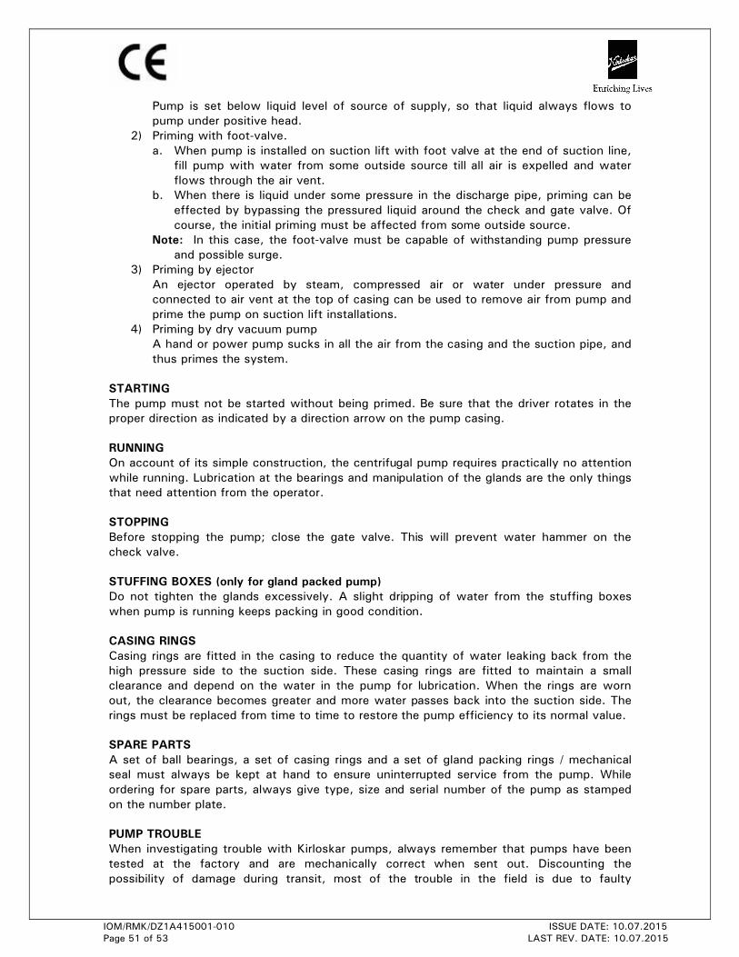
IOM/RMK/DZ1A415001-010 ISSUE DATE: 10.07.2015
Page 51 of 53 LAST REV. DATE: 10.07.2015
Pump is set below liquid level of source of supply, so that liquid always flows to
pump under positive head.
2) Priming with foot-valve. a. When pump is installed on suction lift with foot valve at the end of suction line,
fill pump with water from some outside source till all air is expelled and water
flows through the air vent.
b. When there is liquid under some pressure in the discharge pipe, priming can be effected by bypassing the pressured liquid around the check and gate valve. Of
course, the initial priming must be affected from some outside source.
Note: In this case, the foot-valve must be capable of withstanding pump pressure
and possible surge.
3) Priming by ejector An ejector operated by steam, compressed air or water under pressure and
connected to air vent at the top of casing can be used to remove air from pump and
prime the pump on suction lift installations.
4) Priming by dry vacuum pump A hand or power pump sucks in all the air from the casing and the suction pipe, and
thus primes the system.
STARTING
The pump must not be started without being primed. Be sure that the driver rotates in the
proper direction as indicated by a direction arrow on the pump casing.
RUNNING
On account of its simple construction, the centrifugal pump requires practically no attention
while running. Lubrication at the bearings and manipulation of the glands are the only things
that need attention from the operator.
STOPPING
Before stopping the pump; close the gate valve. This will prevent water hammer on the
check valve.
STUFFING BOXES (only for gland packed pump)
Do not tighten the glands excessively. A slight dripping of water from the stuffing boxes
when pump is running keeps packing in good condition.
CASING RINGS
Casing rings are fitted in the casing to reduce the quantity of water leaking back from the
high pressure side to the suction side. These casing rings are fitted to maintain a small
clearance and depend on the water in the pump for lubrication. When the rings are worn
out, the clearance becomes greater and more water passes back into the suction side. The
rings must be replaced from time to time to restore the pump efficiency to its normal value.
SPARE PARTS
A set of ball bearings, a set of casing rings and a set of gland packing rings / mechanical
seal must always be kept at hand to ensure uninterrupted service from the pump. While
ordering for spare parts, always give type, size and serial number of the pump as stamped
on the number plate.
PUMP TROUBLE
When investigating trouble with Kirloskar pumps, always remember that pumps have been
tested at the factory and are mechanically correct when sent out. Discounting the
possibility of damage during transit, most of the trouble in the field is due to faulty
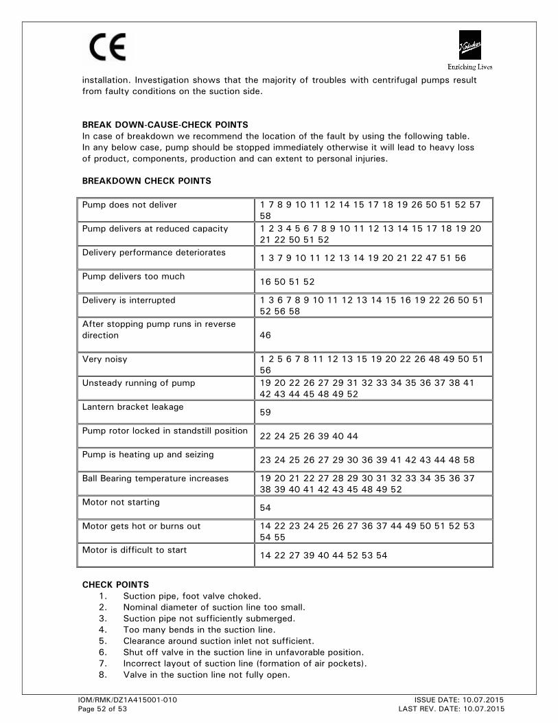
IOM/RMK/DZ1A415001-010 ISSUE DATE: 10.07.2015
Page 52 of 53 LAST REV. DATE: 10.07.2015
installation. Investigation shows that the majority of troubles with centrifugal pumps result
from faulty conditions on the suction side.
BREAK DOWN-CAUSE-CHECK POINTS
In case of breakdown we recommend the location of the fault by using the following table.
In any below case, pump should be stopped immediately otherwise it will lead to heavy loss
of product, components, production and can extent to personal injuries.
BREAKDOWN CHECK POINTS
Pump does not deliver
1 7 8 9 10 11 12 14 15 17 18 19 26 50 51 52 57
58
Pump delivers at reduced capacity
1 2 3 4 5 6 7 8 9 10 11 12 13 14 15 17 18 19 20
21 22 50 51 52
Delivery performance deteriorates
1 3 7 9 10 11 12 13 14 19 20 21 22 47 51 56
Pump delivers too much
16 50 51 52
Delivery is interrupted
1 3 6 7 8 9 10 11 12 13 14 15 16 19 22 26 50 51
52 56 58
After stopping pump runs in reverse
direction
46
Very noisy
1 2 5 6 7 8 11 12 13 15 19 20 22 26 48 49 50 51
56
Unsteady running of pump
19 20 22 26 27 29 31 32 33 34 35 36 37 38 41
42 43 44 45 48 49 52
Lantern bracket leakage
59
Pump rotor locked in standstill position
22 24 25 26 39 40 44
Pump is heating up and seizing
23 24 25 26 27 29 30 36 39 41 42 43 44 48 58
Ball Bearing temperature increases
19 20 21 22 27 28 29 30 31 32 33 34 35 36 37
38 39 40 41 42 43 45 48 49 52
Motor not starting
54
Motor gets hot or burns out
14 22 23 24 25 26 27 36 37 44 49 50 51 52 53
54 55
Motor is difficult to start
14 22 27 39 40 44 52 53 54
CHECK POINTS
1. Suction pipe, foot valve choked.
2. Nominal diameter of suction line too small.
3. Suction pipe not sufficiently submerged.
4. Too many bends in the suction line.
5. Clearance around suction inlet not sufficient.
6. Shut off valve in the suction line in unfavorable position.
7. Incorrect layout of suction line (formation of air pockets).
8. Valve in the suction line not fully open.
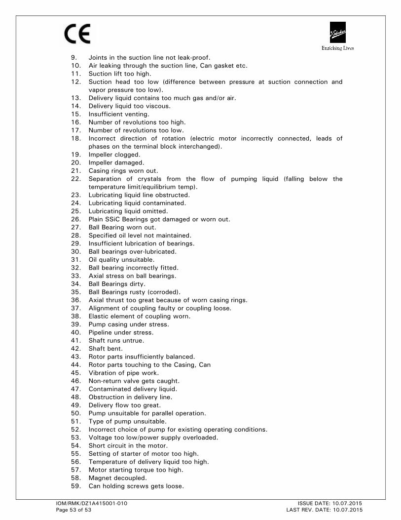
IOM/RMK/DZ1A415001-010 ISSUE DATE: 10.07.2015
Page 53 of 53 LAST REV. DATE: 10.07.2015
9. Joints in the suction line not leak-proof.
10. Air leaking through the suction line, Can gasket etc.
11. Suction lift too high.
12. Suction head too low (difference between pressure at suction connection and
vapor pressure too low).
13. Delivery liquid contains too much gas and/or air.
14. Delivery liquid too viscous.
15. Insufficient venting.
16. Number of revolutions too high.
17. Number of revolutions too low.
18. Incorrect direction of rotation (electric motor incorrectly connected, leads of
phases on the terminal block interchanged).
19. Impeller clogged.
20. Impeller damaged.
21. Casing rings worn out.
22. Separation of crystals from the flow of pumping liquid (falling below the
temperature limit/equilibrium temp).
23. Lubricating liquid line obstructed.
24. Lubricating liquid contaminated.
25. Lubricating liquid omitted.
26. Plain SSiC Bearings got damaged or worn out.
27. Ball Bearing worn out.
28. Specified oil level not maintained.
29. Insufficient lubrication of bearings.
30. Ball bearings over-lubricated.
31. Oil quality unsuitable.
32. Ball bearing incorrectly fitted.
33. Axial stress on ball bearings.
34. Ball Bearings dirty.
35. Ball Bearings rusty (corroded).
36. Axial thrust too great because of worn casing rings.
37. Alignment of coupling faulty or coupling loose.
38. Elastic element of coupling worn.
39. Pump casing under stress.
40. Pipeline under stress.
41. Shaft runs untrue.
42. Shaft bent.
43. Rotor parts insufficiently balanced.
44. Rotor parts touching to the Casing, Can
45. Vibration of pipe work.
46. Non-return valve gets caught.
47. Contaminated delivery liquid.
48. Obstruction in delivery line.
49. Delivery flow too great.
50. Pump unsuitable for parallel operation.
51. Type of pump unsuitable.
52. Incorrect choice of pump for existing operating conditions.
53. Voltage too low/power supply overloaded.
54. Short circuit in the motor.
55. Setting of starter of motor too high.
56. Temperature of delivery liquid too high.
57. Motor starting torque too high.
58. Magnet decoupled.
59. Can holding screws gets loose.

KIRLOSKAR BROTHERS LIMITEDA Kirloskar Group Company
Established 1888
GLOBAL HEADQUARTERS“Yamuna”, S. No. 98/3 to 7, Baner, Pune – 411045, India
Phone:+91-20-27214444 Email: [email protected]
REGISTERED OFFICEUdyog Bhavan, Tilak Road, Pune – 411002, India
Phone: +91-20-24440156 Fax: +91-24440156
GLOBAL PRESENCECambodia │ Egypt │ India │ Lao PDR │ Senegal │ South Africa │ Thailand │ The Netherlands
│ United Arab Emirates │ United Kingdom │ United States of America │ Vietnam
www.kirloskarpumps.com
The NetherlandsIndiaSouth AfricaU.S.A.United Kingdom
OUR COMPANIES