Embed Size (px)
Citation preview
200CW Installation Instructions
Revised April 2014 [email protected] Page 1
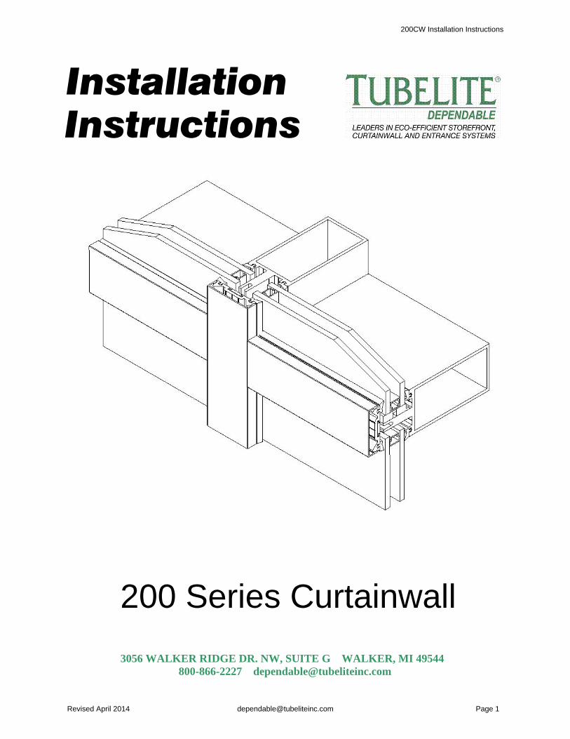
Installation Instructions
200 Series Curtainwall
3056 WALKER RIDGE DR. NW, SUITE G WALKER, MI 49544 800-866-2227 [email protected]

200CW Installation Instructions
Revised April 2014 [email protected] Page 2
TABLE OF CONTENTS
GENERAL CONSTRUCTION NOTES PARTS LIST ELEVATION DETAILS FRAME FABRICATION Step 1: Determine Frame Size Determine Frame Width Determine Frame Height Step 2: Cut Mullions to Size Step 3: Cut Pressure Plates, Snap-on Face Covers and Fillers to Length Step 4: Drill Weep Holes in Horizontal Pressure Plate Step 5: Mill Weep Slot in Horizontal Snap-on Cover Step 6: Drill Slots in Horizontal Step 7: Notch Sills and Heads Step 8: Notch Horizontal in Final Bay (if necessary) Step 9: Fasten Splice Sleeves in Lower Segments of Verticals (if necessary) Step 10: Add Steel Reinforcing (if necessary) CURTAINWALL INSTALLATION Step 11: Attach Shear Block Step 12: Butt Sill Anchor to Side of Mullion Step 13: Fasten Sill Anchor to Masonry Step 14: Slide Horizontal Onto Shear Block Step 15: Slide Horizontal Onto Sill Anchor Clip Step 16: Seal Joints Between Verticals and Horizontals Step 17: Install Water Dams Step 17: Install Water Dam (SSG) Step 18: Apply Sealant Around Water Dam Step 19: Press Vertical Gaskets Into Vertical Members Step 20: Press Horizontal Gaskets Into Horizontal Members Step 21: Place Setting Blocks Step 22: Install Glass Step 23: Press Glazing Gaskets Into Vertical Pressure Plates Step 24: Fasten Vertical Pressure Plate and Snap-on Cover Step 25: Press Glazing Gaskets Into Horizontal Pressure Plates Step 26: Screw Horizontal Pressure Plate Into Place Step 27: Seal Horizontal Pressure Plate Screw Step 28: Install Horizontal Snap-on Cover Step 29: Insert Backing RodCONNECTION AT PERIMETER Return Leg Pressure Plate F Perimeter RunnerCORNER CONDITION Outside 90 Degree CornerSUNSHADE ATTACHMENT
34810101011111213131414151617181819192020212122232324252626272728292930313132333334

200CW Installation Instructions
Revised April 2014 [email protected] Page 3
GENERAL CONSTRUCTION NOTES
1. These instructions cover typical product application, fabrication, installation and standard conditions and aregeneral in nature. They provide useful guidelines, but the final drawings may include additional details specific tothis project. Any conflict or discrepancies must be clarified prior to execution.
2. Materials stored at the job site must be kept in a safe place protected from possible damage by other trades. Stack with adequate separation so materials will not rub together, and store off the ground. Cardboard or paperwrapped materials must be kept dry. Check arriving materials for quantity and keep record of where variousmaterials are stored.
3. All field welding must be done in accordance with AISC guidelines. All aluminum and glass should be shieldedfrom field welding to avoid damage from weld splatter. Results will be unsightly and may be structurally unsound. Advise general contractor and other trades accordingly.
4. Coordinate protection of installed work with general contractor and/or other trades.
5. Coordinate sequence of other trades which affect framing installation with the general contractor (e.g. fireproofing, back up walls, partitions, ceilings, mechanical ducts, HVAC, etc.).
6. General contractor should furnish and guarantee bench marks, offset lines and opening dimensions. Theseitems should be checked for accuracy before proceeding with erection. Make certain that all adjacent substrateconstruction is in accordance with the contract documents and/or approved shop drawings. If not, notify thegeneral contractor in writing before proceeding with installation because this could constitute acceptance ofadjacent substrate construction by others.
7. Isolate all aluminum to be placed directly in contact with masonry or other incompatible materials with a heavycoat of zinc chromate or bituminous paint.
8. Sealant selection is the responsibility of the erector, installer and/or glazing contractor and must be approvedby the sealant manufacturer with regard to application and compatibility for its intended use. All sealants must beused in strict accordance with the manufacturer’s instructions and applied only by trained personnel to surfaces thathave been properly prepared.
9. Sealant must be compatible with all materials with which they have contact, including other sealant surfaces. Consult sealant manufacturer for recommendations relative to shelf life, compatibility, cleaning of substrate,priming, tooling adhesion, etc.
10. Drainage gutters and weep holes must be kept clean at all times. Tubelite will not accept responsibility forimproper drainage as a result of clogged gutters and weep holes.
11. This product requires clearances at head, sill and jambs to allow for thermal expansion and contraction. Referto final distribution drawings for joint sizes. Joints smaller than ¼” may be subject to failure. Consult your sealantsupplier. 12. All materials are to be installed plumb, level and true with regard to established bench marks and columncenter lines established by the general contractor and checked by the erector, installer and/or glazing contractor.
13. Cleaning of exposed aluminum surfaces should be done per AAMA recommendations.
14. Due to varying perimeter conditions and job performance requirements, anchor fasteners are not specified inthese instructions. For anchor fastening, refer to the shop drawings or consult the fastener supplier.
15. Check tubeliteinc.com for any updates on installation instructions.
200CW Installation Instructions
Revised April 2014 [email protected] Page 4
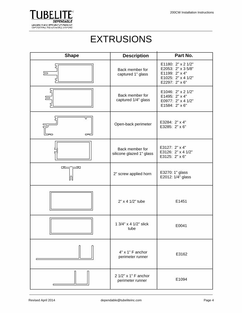
EXTRUSIONS
Part No.Shape Description
Back member forcaptured 1" glass
E1180: 2" x 2 1/2"E2053: 2" x 3 5/8"E1199: 2" x 4"E1025: 2" x 4 1/2"E2297: 2" x 6"
Open-back perimeter E3284: 2" x 4"E3285: 2" x 6"
Back member forsilicone glazed 1" glass
E3127: 2" x 4"E3126: 2" x 4 1/2"E3125: 2" x 6"
2" screw applied horn E3270: 1" glassE2012: 1/4" glass
2" x 4 1/2" tube E1451
1 3/4" x 4 1/2" slicktube
E0041
4" x 1" F anchorperimeter runner
E3162
Back member forcaptured 1/4" glass
E1046: 2" x 2 1/2"E1495: 2" x 4"E0977: 2" x 4 1/2"E1584: 2" x 6"
2 1/2" x 1" F anchorperimeter runner E1094

200CW Installation Instructions
Revised April 2014 [email protected] Page 5
Part No.Shape Description
Snap cover
E0968: 2" x 1/2"E0992: 2 x 3/4"E2606: 2" x 1"E1214: 2" x 1 1/2"E0978: 2" x 2"E3642: 2" x 3" E1587: 4" x 3/4"
O.S. corner adapter E2101
I.S. corner adapter E2100
Pocket reducer for1/4" glazing
E4TB69
Pocket reducer for 3/8"- 1/2" glazing
E4TB80
EXTRUSIONS
Glass pocket - closureplate for 1" glass
E3192
Return legpressure plate E1062

200CW Installation Instructions
Revised April 2014 [email protected] Page 6
Part No.
ACCESSORIESShape Description
Insulated pressure plate M1061
Temporary glazing clip P1193
Back member splice
P1625A: For E1180P1625B: For E1199, E1495P1625C: For E0977, E1025P1625D: For E1584, E2297P1625E: For E2053P1625F: For E3125P1625G: For E3126P1625H: For E3127
Insulator for M1061 P914
Temporary glazing clip(use with
E3125/3126/3127)P1108
Setting block for 1"glass
P946: EPDMP947: Silicone
Snap cover spliceP1626A: 1/2"P1626B: 3/4"
Fixed glazing gasketPTB28: 1/8"PTB31: 3/16"
Silicone glazing spacer P1690
Water dam for 1"glazed system P945
Water dam for siliconeglazed verticals P1629
P1265: .3125" hole diameterP1266: .375"P1267: .4375"
Locking lug
Shear block
P1320A: 4" back memberP1320B: 6"P1320C: 4 1/2"P1320D: 2 1/2"P1320F: 3 5/8"P1320K: 4" open back memberP1320L: 6" open back member
Return legpressure plate
M1202

200CW Installation Instructions
Revised April 2014 [email protected] Page 7
Part No.
ACCESSORIESShape Description
Sill anchor
P1318A: 4" back memberP1318B: 6"P1318C: 4 1/2"P1318D: 2 1/2"P1318F: 3 5/8"P1318K: 4" open back memberP1318L: 6" open back member
Head anchor
P1543: 4" back memberP1543A: 6"P1543B: 4 1/2"P1543C: 2 1/2"P1543E: 3 5/8"P1543J: 4" open back memberP1543K: 6" open back member
F anchor
P2078A: For E1215P2078B: E1180P2078C: E2053P2078D: E1199P2078E: E1025P2078F: E2297P2078G: E3127P2078H: E3126P2078J: E3125
T anchor
P2079A: For E1215P2079B: E1180P2079C: E2053P2079D: E1199P2079E: E1025P2079F: E2297P2079G: E3127P2079H: E3126P2079J: E3125
#14-14 x 1/2" typeB hex head S139
#10 x 1/2" type BPhillips truss head
S191
#14-14 x 1/2" typeB hex head
S270
S357#10 UNC x 5/8"
type B hex washerhead
Pipe sleeve spacerfor 3/8" diameter bolt
P2028

200CW Installation Instructions
Revised April 2014 [email protected] Page 10
FRAME FABRICATION
Step 1: Determine Frame Size
Determine Width
∙ Check that the opening issquare and plumb at both ends.Units must be installed in a truerectangle.
∙ Measure the width of theopening at the top, middleand bottom.∙ Select the smallestdimension measured. Todetermine the frame widthto be used, subtract aminimum of 1” from thesmallest measured width, toallow a minimum of 1/2” ateach jamb for shimmingand caulking. ∙ Allow a larger clearance ifnecessary to accommodatebuilding tolerances, anout-of-square opening,anticipated thermalexpansion within the unitand/or according to projectneeds.
1/2" min. 1/2" min.

200CW Installation Instructions
Revised April 2014 [email protected] Page 11
Determine Height
∙ Measure the height of theopening in several placesalong the entire length of theopening.∙ To determine the frameheight to be used, select thesmallest dimension measuredand subtract 1” to allow aminimum of 1/2" at sill andhead for shimming andcaulking. ∙ Allow a larger clearance ifnecessary to accommodatebuilding tolerances, anout-of-square opening,anticipated thermal expansionwithin the unit and/oraccording to project needs.
1/2" min.
1/2" min.
Step 2: Cut Mullions to Size
∙ Verticals should be frame height found in Step #1 (rough opening height minusclearances).• Vertical framing members run through as shown in the elevation overview.• Cut horizontal framing members to the daylight opening (the distance betweenverticals) minus 1/16" total.
200CW Installation Instructions
Revised April 2014 [email protected] Page 12
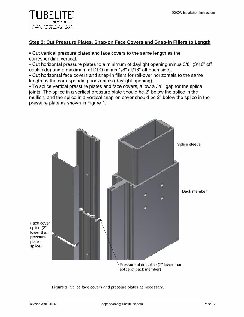
Step 3: Cut Pressure Plates, Snap-on Face Covers and Snap-in Fillers to Length
∙ Cut vertical pressure plates and face covers to the same length as thecorresponding vertical.∙ Cut horizontal pressure plates to a minimum of daylight opening minus 3/8" (3/16" offeach side) and a maximum of DLO minus 1/8" (1/16" off each side).∙ Cut horizontal face covers and snap-in fillers for roll-over horizontals to the samelength as the corresponding horizontals (daylight opening).∙ To splice vertical pressure plates and face covers, allow a 3/8" gap for the splicejoints. The splice in a vertical pressure plate should be 2" below the splice in themullion, and the splice in a vertical snap-on cover should be 2" below the splice in thepressure plate as shown in Figure 1.
Face coversplice (2"lower thanpressureplatesplice)
Figure 1: Splice face covers and pressure plates as necessary.
Pressure plate splice (2" lower thansplice of back member)
Splice sleeve
Back member

200CW Installation Instructions
Revised April 2014 [email protected] Page 13
Step 4: Drill Weep Holes inHorizontal Pressure Plate
∙ Drill three weep holes in thehorizontal pressure plate: twohalfway between the center andthe end of the pressure plate andone at the center of the pressureplate, as shown in Figure 2.∙ Drill all weep holes 5/16" abovethe groove which marks thecenter line of the pressure plate.∙ Pressure plate is pre-punchedwith holes for fasteners. Drilladditional holes as required toensure end holes are a minimumof 2” and maximum of 4” from thevertical and then assume a 10”center to center spacing for theremainder.
Figure 2: Install three weep holes in thehorizontal pressure plate.
Center line
Weep holes
Step 5: Mill WeepSlot in HorizontalSnap-on Cover
∙ Mill a weep slot a maximum of 1"from the end of thecover. The weepslots are to be 1/4"wide x 1/2" long asshown in Figure 3.
Figure 3: Mill a weep slot in the horizontal snap-on cover.
1" max.
3/16"
2" min. -4" max.
1/2" x 1/4"weep slot
200CW Installation Instructions
Revised April 2014 [email protected] Page 14
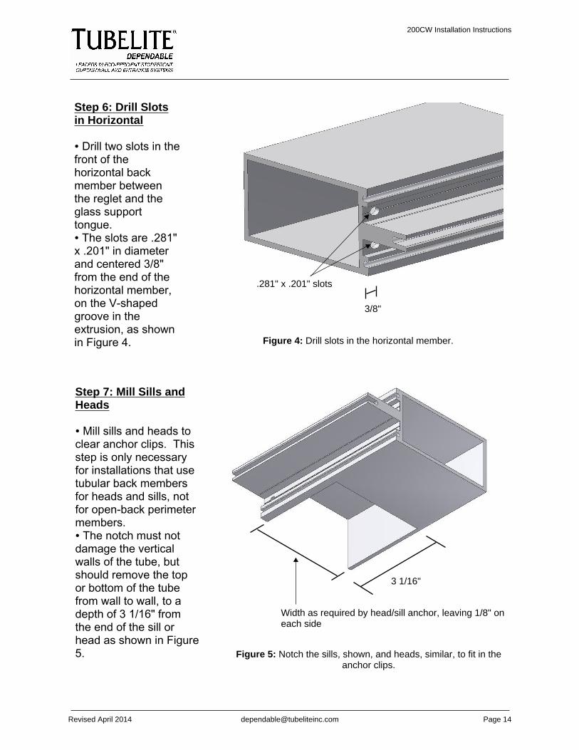
Figure 4: Drill slots in the horizontal member.
Step 6: Drill Slotsin Horizontal
∙ Drill two slots in thefront of thehorizontal backmember betweenthe reglet and theglass supporttongue.∙ The slots are .281"x .201" in diameterand centered 3/8"from the end of thehorizontal member,on the V-shapedgroove in theextrusion, as shownin Figure 4.
Step 7: Mill Sills andHeads
∙ Mill sills and heads toclear anchor clips. Thisstep is only necessaryfor installations that usetubular back membersfor heads and sills, notfor open-back perimetermembers.∙ The notch must notdamage the verticalwalls of the tube, butshould remove the topor bottom of the tubefrom wall to wall, to adepth of 3 1/16" fromthe end of the sill orhead as shown in Figure5. Figure 5: Notch the sills, shown, and heads, similar, to fit in the
anchor clips.
3 1/16"
Width as required by head/sill anchor, leaving 1/8" oneach side
3/8"
.281" x .201" slots
200CW Installation Instructions
Revised April 2014 [email protected] Page 15
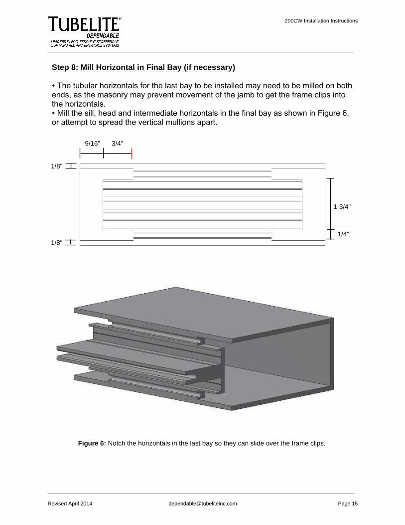
Step 8: Mill Horizontal in Final Bay (if necessary)
∙ The tubular horizontals for the last bay to be installed may need to be milled on bothends, as the masonry may prevent movement of the jamb to get the frame clips intothe horizontals.∙ Mill the sill, head and intermediate horizontals in the final bay as shown in Figure 6,or attempt to spread the vertical mullions apart.
Figure 6: Notch the horizontals in the last bay so they can slide over the frame clips.
1/8"
9/16" 3/4"
1/8"
1 3/4"
1/4"

200CW Installation Instructions
Revised April 2014 [email protected] Page 16
Step 9: Fasten Splice Sleeves in Lower Segments of Verticals (if necessary)
∙ Consult the approved shop drawings to see what size of 1/4-20 flat-head fasteners(minimum 3/4") to use when fastening the splice sleeves to the lower segments of theverticals.∙ Drill and countersink four holes on both sides of the verticals (eight holes pervertical), in the locations shown on the approved shop drawings. The diameter of theholes should be appropriate for the fasteners.∙ Slide a splice sleeve into the end of the vertical mullion where holes were just drilledas shown below. The splice sleeve is 10" long. Half its length should be inside themullion, and half should project out the end of the mullion.
Sealant
Outline ofpressureplate
1/4" steel angledead load clip(not by Tubelite)
1" insulatedglass
Splice.040aluminumsplice
Hard splice
Splice sleeve

200CW Installation Instructions
Revised April 2014 [email protected] Page 17
Steel
Fastener
Step 10: Add SteelReinforcement (ifnecessary)
• Refer to approvedshop drawings todetermine whether theapplication requiressteel reinforcement.• If reinforcement isrequired, cut steel to 6”less than the frameheight.• Slide the steel into thevertical mullion from oneend, recessing it 3” infrom the end of thevertical.• Drill pilot holes throughthe steel and the verticalmullion at the center ofeach horizontal, andanchor the steel to thevertical using fastenersof an appropriate size(not by Tubelite) asshown at right.

200CW Installation Instructions
Revised April 2014 [email protected] Page 18
CURTAINWALL INSTALLATIONStep 11: Attach Shear Block
∙ Drill .201" diameter holes into the side of the vertical back member as shown inFigure 7. ∙ Attach an intermediate shear block for the corresponding vertical back memberusing S139 fasteners. For dimensions, examine the table below.∙ Dimensions also apply to where the head and sill anchors meet the vertical.However, the drilled holes must be 1" from the top and bottom of the mullion.
Clip
P1320A
P1320B
P1320C
P1320D
P1320F
P1320K
P1320L
Dim. A
2.250"
4.218"
2.250"
0.750"
1.875"
1.750"
3.750"
Dim. B
0.886"
0.897"
1.136"
0.886"
0.886"
1.136"
1.136"
Use With Extrusion
E1199, E1495, E3283
E1584, E2297
E0977, E1025
E1046, E1180
E2053
E3284
E3285
Glass
1", 1/4"
1", 1/4"
1", 1/4"
1"
1"
1"
1"
Tube depth
4"
6"
4 1/2"
2 1/2"
3 5/8"
4"
6"
Figure 7: Attach shear block to the vertical back member.
Dim. A
Dim.B
S139
200CW Installation Instructions
Revised April 2014 [email protected] Page 19
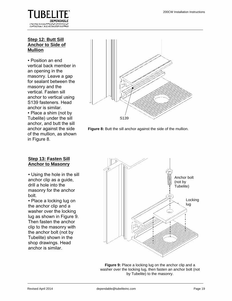
Step 12: Butt SillAnchor to Side ofMullion
∙ Position an endvertical back member inan opening in themasonry. Leave a gapfor sealant between themasonry and thevertical. Fasten sillanchor to vertical usingS139 fasteners. Headanchor is similar.∙ Place a shim (not byTubelite) under the sillanchor, and butt the sillanchor against the sideof the mullion, as shownin Figure 8.
Figure 8: Butt the sill anchor against the side of the mullion.
Step 13: Fasten SillAnchor to Masonry
∙ Using the hole in the sillanchor clip as a guide,drill a hole into themasonry for the anchorbolt. ∙ Place a locking lug onthe anchor clip and awasher over the lockinglug as shown in Figure 9.Then fasten the anchorclip to the masonry withthe anchor bolt (not byTubelite) shown in theshop drawings. Headanchor is similar.
Figure 9: Place a locking lug on the anchor clip and awasher over the locking lug, then fasten an anchor bolt (not
by Tubelite) to the masonry.
S139
Anchor bolt(not byTubelite)
Lockinglug

200CW Installation Instructions
Revised April 2014 [email protected] Page 20
Step 15: Slide HorizontalOnto Sill Anchor Clip
∙ Seal the perimeter of thesill anchor to the mullion.∙ Seal the ends of thehorizontal that will attachto the vertical.∙ Slide the end of the sillonto the sill anchor clip,and place shims under thesill as necessary to makeit level, and to create asealant gap.∙ Slide the end of thehorizontal onto the frameclip, and fasten thehorizontal to the frame clipusing two S270 fasteners,as shown in Figure 11.∙ Seal fastener heads.∙ For perimeter anchoringand connection details, goto page 30.
Figure 11: Slide the end of the horizontal onto the sill anchor andfasten using two S270 fasteners.
S270
Cap seal
Seal perimeterof sill anchor
Step 14: SlideHorizontal OntoShear Block
∙ Seal the perimeterof the shear block tothe mullion.∙ Seal the ends ofthe horizontal thatwill attach to thevertical.∙ Slide the end of thehorizontal onto theframe clip, andfasten the horizontalto the frame clipusing two S270fasteners, as shownin Figure 10.∙ Seal fastenerheads.
Seal ends ofhorizontal
Cap seal
S270
Seal perimeterof shear block
Seal ends ofhorizontal
Figure 10: Slide the end of the horizontal onto the shear block andfasten using two S270 fasteners.

200CW Installation Instructions
Revised April 2014 [email protected] Page 21
Step 16: SealJointsBetweenVerticals andHorizontals
∙ Seal the jointsbetweenverticals andhorizontals, asshown in Figure12. ∙ Tool thesealant into thevoids, andclean offexcess sealant.
Figure 12: Seal the joints between verticals and horizontals.
Step 17: InstallWater Dams
∙ Wherever ahorizontal meetsa vertical, applya bead of butylsealant acrossthe verticalmember, asshown in Figure13.∙ Insert a waterdam into the gapbetween thehorizontal andvertical memberswhere the sealantwas just applied. Figure 13: After sealing the gap between the horizontal and
vertical, insert a water dam into the gap.
Water dam
PTI 707 butyl sealantor equivalent
PTI 707 butylsealant orequivalent
Sealant

200CW Installation Instructions
Revised April 2014 [email protected] Page 22
Water dam(P1629)
PTI 707 butylsealant orequivalent
PTI 707butylsealant orequivalent
Step 17: Install Water Dam (SSG)
∙ Wherever a horizontal meets an SSG vertical, apply a bead of butyl sealant acrossthe vertical member, as shown in Figure 14.∙ Insert a water dam into the gap between the horizontal and vertical members wherethe sealant was just applied.
Figure 14: After applying sealant to the gap between the horizontal and vertical, insert a waterdam into the gap.

200CW Installation Instructions
Revised April 2014 [email protected] Page 23
Step 18: ApplySealant AroundWater Dam
∙ Apply a bead ofbutyl sealant aroundthe perimeter of eachwater dam. Also applysealant across thefront of the water damstretching across thetongue of the verticalmember, as shown inFigure 15.∙ Tool the sealant intoall voids and tool toensure the sealant willnot contact the edgeof the glass.∙ Infiltrated water mustalso be able to passfreely around theglass and out theweep hole.
Figure 15: Apply a bead of sealant around the perimeter of eachwater dam.
Step 19: Press VerticalGaskets Into VerticalMembers
∙ Seal the heads of theS270 fasteners on thehorizontal member.∙ Press the verticalgaskets into their regletson the vertical member,as shown in Figure 16. Press the ends of thegaskets into the sealantaround the water dams.
Figure 16: Press the vertical gaskets into theirreglets on the vertical member.
Gasket
Gasket
PTI 707 butylsealant orequivalent
Water flow

200CW Installation Instructions
Revised April 2014 [email protected] Page 24
Step 20: Press Horizontal Gaskets Into Horizontal Members
∙ Apply butyl sealant where the vertical gaskets will meet the horizontal gaskets asshown in Figure 17.∙ Press horizontal gaskets into their reglets on the horizontal back members asshown in Figure 18. Press the ends into the sealant.
Figure 18: Press the horizontal gaskets into their reglets on the horizontal member.
Figure 17: Apply butyl sealant where the vertical gaskets will meet the horizontal gaskets.
Gasket
Gasket
PTI 707butylsealant orequivalent

200CW Installation Instructions
Revised April 2014 [email protected] Page 25
Step 21: Place SettingBlocks
∙ Place setting blocks atthe quarter points of eachlight (two setting blocksper light) or as required byshop drawings, as shownin Figure 19.∙ Use P946 for 1" glassand P948 for 1/4" glass.
Figure 19: Place setting blocks at the quarter point ofthe light or as required by shop drawings.
Setting block

200CW Installation Instructions
Revised April 2014 [email protected] Page 26
Step 22:Install Glass
∙ Glass size iscalculated asdaylightopening + 1"horizontallyand vertically.∙ Place glasson settingblocks, asshown inFigure 20.
Figure 20: Place glass on setting blocks.
Step 23: PressGlazing GasketsInto VerticalPressure Plate
∙ Press glazinggaskets (PTB28)into the reglets ofthe verticalpressure plate, asshown in Figure21.
Glass
Glass
Figure 21: Press glazing gaskets into the reglets of the vertical pressureplate.

200CW Installation Instructions
Revised April 2014 [email protected] Page 27
Figure 22: Place the vertical pressure plate and snap-on cover.
Step 24: FastenVertical PressurePlate and Snap-onCover
∙ Fasten the verticalpressure plate to themullion as shown inFigure 22 with anS357 fastener andglazing gaskets(PTB28).∙ Torque of 30-40in.-lbs. should beused to fasten thepressure plate.∙ Install the verticalsnap-on cover asshown in Figure 22.
Pressureplate
Snap-on cover
Step 25: PressGlazingGaskets IntoHorizontalPressure Plate
∙ Press glazinggaskets(PTB28) into thereglets of thehorizontalpressure plate. ∙ Butter theends of thegaskets in thehorizontalpressure platewith butylsealant asshown in Figure23. Figure 23: Butter the ends of the gaskets in the horizontal pressure plate
with butyl sealant.
PTI 707 butylsealant orequivalent
S357
Gasket(PTB28)

200CW Installation Instructions
Revised April 2014 [email protected] Page 28
Step 26: FastenHorizontal PressurePlate Into Place
∙ Fasten thehorizontal pressureplate in place with anS357 fastener asshown in Figure 24.∙ Torque of 30-40in.-lbs. should beused to fasten on thepressure plate.∙ Seal the jointbetween thehorizontal pressureplate and the verticalsnap-on cover, andtool the sealant intothe void, as shown inFigure 25. Figure 24: Fasten the horizontal pressure plate into place.
Sealant
Figure 25: Seal the joint between the horizontal pressure plate and vertical snap-on cover.
S357

200CW Installation Instructions
Revised April 2014 [email protected] Page 29
Step 27: SealHorizontalPressure PlateFastener
∙ Seal the head ofthe fastenerholding thehorizontal pressureplate, as shown inFigure 26.
Figure 26: Seal the head of the fastener holding the horizontalpressure plate.
Sealant
Step 28: InstallHorizontalSnap-on Cover
∙ Install thehorizontalsnap-on coveras shown inFigure 27.
Figure 27: Install the horizontal snap-on cover.
200CW Installation Instructions
Revised April 2014 [email protected] Page 30
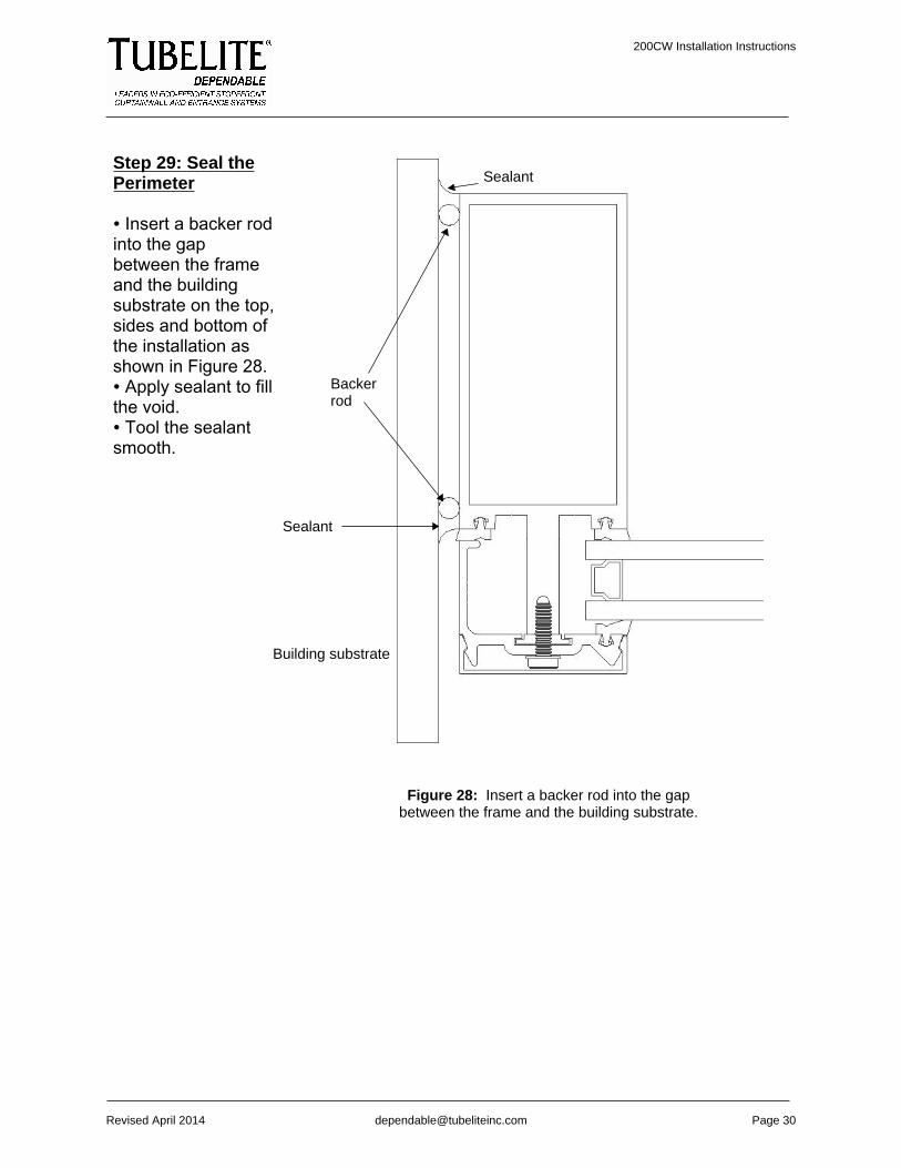
Step 29: Seal thePerimeter
∙ Insert a backer rodinto the gapbetween the frameand the buildingsubstrate on the top,sides and bottom ofthe installation asshown in Figure 28.∙ Apply sealant to fillthe void.∙ Tool the sealantsmooth.
Figure 28: Insert a backer rod into the gapbetween the frame and the building substrate.
Backerrod
Sealant
Sealant
Building substrate
200CW Installation Instructions
Revised April 2014 [email protected] Page 31
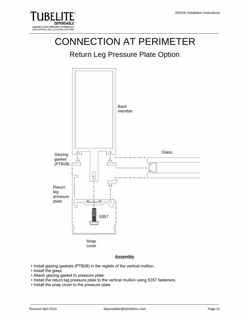
CONNECTION AT PERIMETERReturn Leg Pressure Plate Option
Glass
Backmember
Glazinggasket(PTB28)
Returnlegpressureplate
S357
Snapcover
Assembly
∙ Install glazing gaskets (PTB28) in the reglets of the vertical mullion.∙ Install the glass.∙ Attach glazing gasket to pressure plate.∙ Install the return leg pressure plate to the vertical mullion using S357 fasteners.∙ Install the snap cover to the pressure plate.

200CW Installation Instructions
Revised April 2014 [email protected] Page 32
F Perimeter Runner Option
Backmember
Glass
Glazing gasket(PTB28)
S357
Pressure plate
Snap cover
F perimeterrunner
Assembly
∙ Install an F perimeter runner in the frame opening.∙ Install glazing gaskets (PTB28) in the reglets of thevertical mullion.∙ Apply structural sealant in corner between F perimeterrunner, vertical mullion and glazing gasket, as well aswhere the F perimeter runner will meet the pressureplate.∙ Install the vertical mullion next to the F perimeterrunner.∙ Install the glass.∙ Attach glazing gaskets to pressure plate.∙ Install the pressure plate to the vertical mullion usingS357 fasteners.∙ Install the snap cover to the pressure plate.
Dow Corning 995sealant orequivalent
Dow Corning 995sealant orequivalent
200CW Installation Instructions
Revised April 2014 [email protected] Page 33
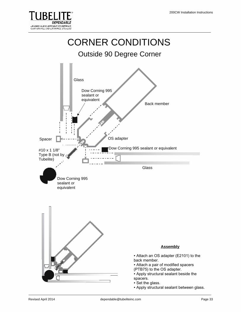
CORNER CONDITIONSOutside 90 Degree Corner
Assembly
∙ Attach an OS adapter (E2101) to theback member.∙ Attach a pair of modified spacers(PTB75) to the OS adapter.∙ Apply structural sealant beside thespacers.∙ Set the glass.∙ Apply structural sealant between glass.
Back member
OS adapter
Glass
Dow Corning 995sealant orequivalent
Glass
Spacer
Dow Corning 995 sealant or equivalent
Dow Corning 995sealant orequivalent
Corning 9#10 x 1 1/8"Type B (not byTubelite)

200CW Installation Instructions
Revised April 2014 [email protected] Page 34
SUNSHADE ATTACHMENT
Assembly
∙ Pre-drill holes at least 3/4" deep into the tongue of the back member where the S424 fasteners will go.∙ Attach sunshade attachment brackets (P3908) to vertical mullion using eight S424 fasteners.
Back member
Sunshadeattachmentbracket (P3908)
S424
200CW Installation Instructions
Revised April 2014 [email protected] Page 35
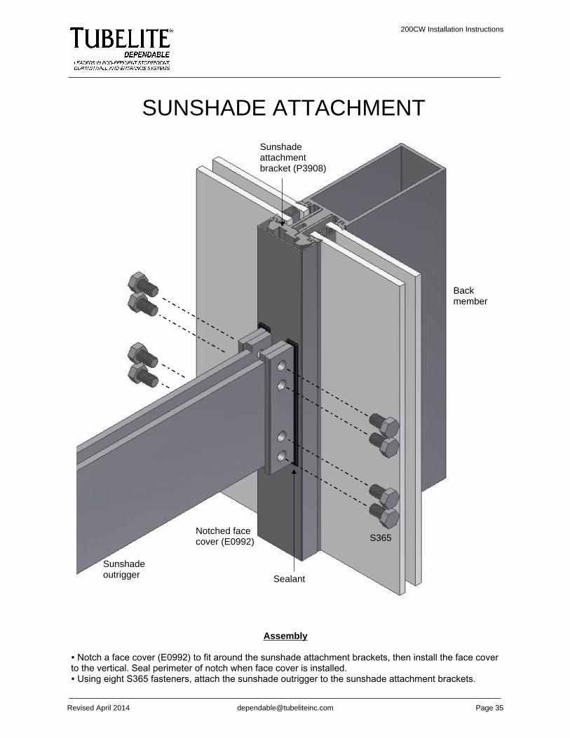
SUNSHADE ATTACHMENT
Assembly
∙ Notch a face cover (E0992) to fit around the sunshade attachment brackets, then install the face coverto the vertical. Seal perimeter of notch when face cover is installed.∙ Using eight S365 fasteners, attach the sunshade outrigger to the sunshade attachment brackets.
Sunshadeoutrigger
Backmember
Sunshadeattachmentbracket (P3908)
S365Notched facecover (E0992)
Sealant