Embed Size (px)
Citation preview
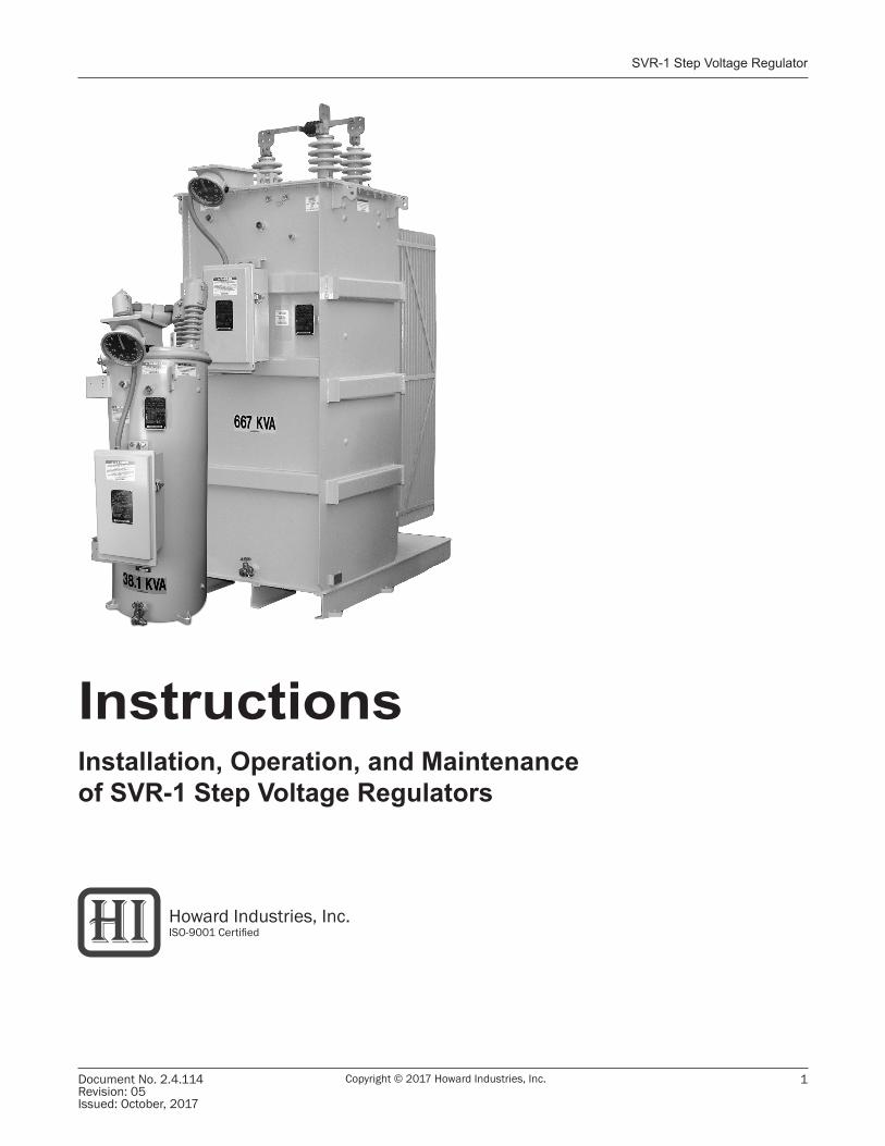
Switch-Pad™ SVR-1 Step Voltage Regulator
Document No. 2.4.114Revision: 05Issued: October, 2017
1Copyright © 2017 Howard Industries, Inc.
InstructionsInstallation, Operation, and Maintenanceof SVR-1 Step Voltage Regulators
Howard Industries, Inc.ISO-9001 Certified
Document 2.4.114SVR-1 Step Voltage Regulator
Copyright © 2017 Howard Industries, Inc. Document No. 2.4.114Revision: 05
Issued: October, 2017
2
READ THIS IMPORTANT SAFETY INFORMATION
Read these instructions carefully and become familiar with the equipment before proceeding with installation, operation, or maintenance activities. This equipment contains extremely hazardous voltages. To prevent death, serious personal injury, or equipment damage, all information in these instructions should be read and observed. Safe use of this equipment is dependent on proper installation, operation, and maintenance procedures.
Certain information in this manual is marked with the words DANGER, WARNING, or CAUTION, which indicate hazards.
• DANGER indicates an imminently hazardous situation which, if not avoided, will result in death or serious personal injury and may also result in damage to the equipment.
• WARNING indicates a potentially hazardous situation which, if not avoided, could result in death or serious personal injury and may also result in equipment damage.
• CAUTION indicates a potentially hazardous situation which, if not avoided, could result in minor or moderate personal injury and may also result in damage to the equipment.
Personnel should not attempt to service this equipment until it has been effectively de-energized, and all high-voltage and low-voltage bushing terminals have been properly grounded. Only qualified personnel should install, maintain, and operate this equipment. Qualified personnel are those who are trained in the installation, maintenance, and operation of high-voltage equipment, trained in the proper use of personal protective equipment (such as rubber gloves, safety glasses, protective clothing, hard hats, etc.) and trained in appropriate first aid procedures.
The instructions contained herein are intended to be a general guide for the installation, operation and maintenance of this equipment, when operated in “Usual Service Conditions” as defined in IEEE Standard C57.15. Although efforts have been made to ensure accuracy and completeness, these instructions do not address every conceivable application or circumstance that might be encountered.
Features presented herein may not be present in all equipment designs. Standard and optional features are subject to change without notice. Howard Industries makes no representation or warranty with respect to and assumes no responsibility for the completeness, accuracy, sufficiency, or usefulness of these instructions.
These instructions do not cover the installation, operation or maintenance of the secondary network protector or any other accessory equipment installed by the user. Users should refer to instructions provided by the manufacturer of such equipment. Questions regarding installation, operation, and maintenance, particularly when encountering unusual or special circumstances not sufficiently covered by these instructions, should be directed to the Howard Industries Transformer Division.
Switch-Pad™ SVR-1 Step Voltage Regulator
Document No. 2.4.114Revision: 05Issued: October, 2017
3Copyright © 2017 Howard Industries, Inc.
TABLE OF CONTENTS
Receiving Inspection, Storage, and Handling .......................................................................................................................... 4 Receiving Inspection ............................................................................................................................................................ 4 Handling ................................................................................................................................................................................ 4 Storage .................................................................................................................................................................................. 4Installation .................................................................................................................................................................................. 5 Introduction .......................................................................................................................................................................... 5 Pre-Installation Checklist ..................................................................................................................................................... 5 Installation Location ............................................................................................................................................................. 6 Mounting ............................................................................................................................................................................... 6 High-Voltage and Grounding Connections .......................................................................................................................... 6 Control Connections ............................................................................................................................................................. 7 Bypass Surge Arrester .......................................................................................................................................................... 7 Lightning Protection ............................................................................................................................................................. 7 Through Fault ........................................................................................................................................................................ 7 50 Hertz Operation .............................................................................................................................................................. 7Placing a Regulator in Service ................................................................................................................................................. 10 Procedure ............................................................................................................................................................................ 10 Checking for Proper Operation .......................................................................................................................................... 11Removing a Regulator from Service ...................................................................................................................................... 12 Procedure ........................................................................................................................................................................... 12 Returning a Regulator to Service .................................................................................................................................... 12Maintenance ........................................................................................................................................................................... 13 General Instructions .......................................................................................................................................................... 13 Operational Checks ........................................................................................................................................................... 13 Insulation Fluid ................................................................................................................................................................... 14 Internal Inspection ............................................................................................................................................................. 14 Vacuum Oil Fill Process ........................................................................................................................................................15 Cooling Fans ....................................................................................................................................................................... 15 Additional Maintenance Instructions ................................................................................................................................ 16 Repair Parts ........................................................................................................................................................................ 16 Warranty Claims ................................................................................................................................................................. 16 Regulator Disposal ............................................................................................................................................................. 16External Parts List ..................................................................................................................................................................... 18
LIST OF FIGURES Figure 1: Recommended method for lifting regulator ....................................................................................................... 4 Figure 2: Typical regulator nameplate ................................................................................................................................ 5 Figure 3: Cover-mounted terminal block ............................................................................................................................. 6 Figure 4: SVR-1 step voltage regulator .............................................................................................................................. 8 Figure 5: Connection diagram, one SVR-1 regulator in a single-phase system ............................................................... 9 Figure 6: Connection diagram, two SVR-1 regulators in an open delta three-phase system .......................................... 9 Figure 7: Connection diagram, three SVR-1 regulators wye connected in a three-phase four-wire system ................... 9 Figure 8: Connection diagram, three SVR-1 regulators delta connected in a three-phase three-wire system ........................ 9 Figure 9: HI-AMP™ switches .............................................................................................................................................. 10 Figure 10: Connector terminal strip (CTS) ........................................................................................................................ 14 Figure 11: Recommended lifting method for untanking regulator internal assembly .................................................. 15 Figure 12: External parts view ........................................................................................................................................... 17

Document 2.4.114SVR-1 Step Voltage Regulator
Copyright © 2017 Howard Industries, Inc. Document No. 2.4.114Revision: 05
Issued: October, 2017
4
RECEIVING INSPECTIONImmediately upon receipt the regulator should be carefully inspected for evidence of shipping damage. The shipping manifest should be checked to make sure all listed materials have been received. Any damage or material discrepancies should be noted on the shipping manifest and a claim should be immediately filed with the freight carrier. Discrepancies should also be brought to the attention of the Howard Industries Regulator Division.
HANDLINGThe regulator can be moved using the lifting lugs on the sides of the tank and a suitably rated lifting sling. Use of a spreader bar is also recommended. Figure 1 illustrates the recommended method for lifting the regulator using a spreader bar. Do not use the cover-mounted lifing eyes for lifting the entire regulator. Cover-mounted lifting eyes are to be used only for untanking the internal assembly. A properly palletized regulator can also be lifted using a forklift truck or pallet jack having the necessary weight handling capacity. Refer to the regulator nameplate for the unit’s weight to determine the suitability of a lifting device.
STORAGEThe regulator should be stored in a manner that will prevent damage. The control cabinet door should be closed and latched.
RECEIVING INSPECTION, STORAGE, AND HANDLING
FIGURE 1: Recommended method for lifting regulator using spreader bar
WARNINGFalling equipment can cause death, serious personal injury, or property damage. When lifting the entire regulator, the tank-mounted lifting lugs must be used. Do not use the cover-mounted lifting eyes to lift the entire regulator. Doing so may cause the cover to fracture or separate completely from the regulator. Cover-mounted lifting eyes should be used only for untanking the internal assembly.
Switch-Pad™ SVR-1 Step Voltage Regulator
Document No. 2.4.114Revision: 05Issued: October, 2017
5Copyright © 2017 Howard Industries, Inc.
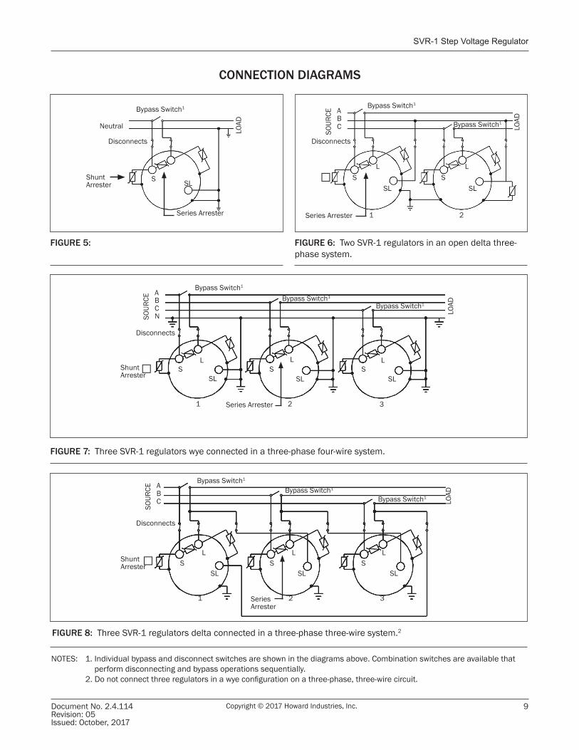
INTRODUCTIONAn SVR-1 regulator can regulate the voltage on a single-phase circuit or one phase of a delta- or wye-connected three-phase circuit as described below and as illustrated in the connection diagrams on page 9. Do not connect three regulators in a wye configuration on a three-phase, three-wire circuit.
• One SVR-1 regulator in a single-phase application• Three SVR-1 regulators connected in a grounded wye
configuration on a four-wire three-phase system• Three SVR-1 regulators connected in a delta
configuration on an ungrounded three-wire three-phase system
• Two SVR-1 regulators connected in an open delta configuration on an ungrounded three-phase system
INSTALLATION
PRE-INSTALLATION CHECKLISTBefore connecting the regulator, the following checks should be made:
1. Check the oil level sight gauge for proper oil level (top oil level visible in gauge). Add ASTM D-3487 Type 2 oil, if the level is found to be low. Check for visible signs of oil leaks.
2. Measure the dielectric strength of the oil per ASTM D-877. If found to be below 24 kV, the oil should be filtered and retested (NOTE: This test is not necessary if the regulator is being installed immediately after receipt from the factory.)
3. Measure power factor from each bushing terminal to tank ground. The reading should be less than 2.0 percent.
4. Inspect the porcelain bushings for damage or signs of oil leaks. If it is suspected that moisture may have entered the regulator, test the oil per ASTM D-3487 (Type 2). A positive indication for moisture will require that the regulator be dried and the oil filtered before placing into service.
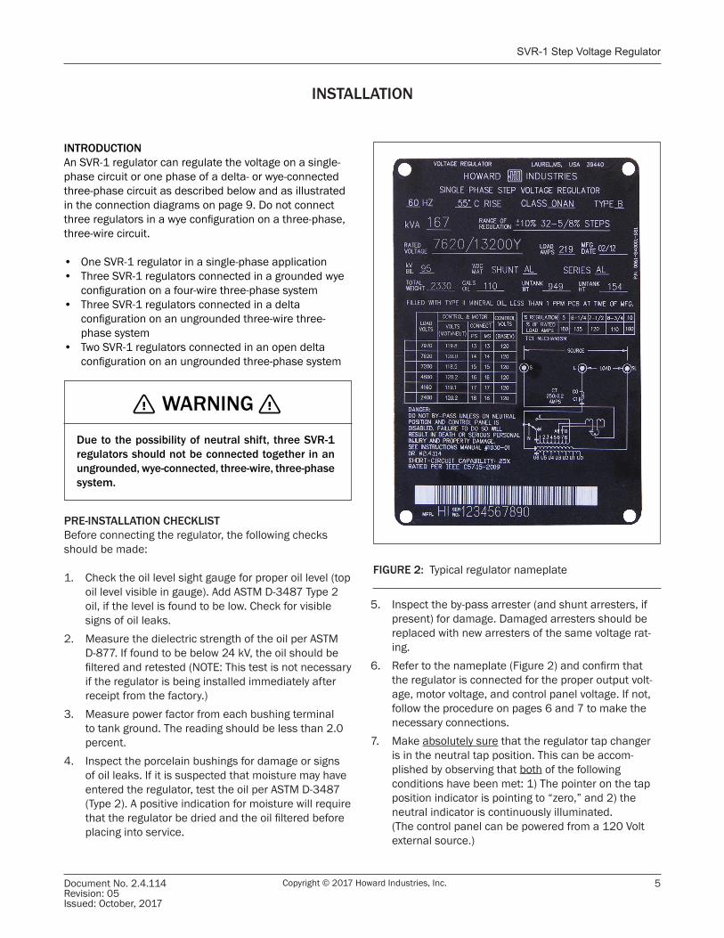
FIGURE 2: Typical regulator nameplate
WARNINGDue to the possibility of neutral shift, three SVR-1 regulators should not be connected together in an ungrounded, wye-connected, three-wire, three-phase system.
5. Inspect the by-pass arrester (and shunt arresters, if present) for damage. Damaged arresters should be replaced with new arresters of the same voltage rat-ing.
6. Refer to the nameplate (Figure 2) and confirm that the regulator is connected for the proper output volt-age, motor voltage, and control panel voltage. If not, follow the procedure on pages 6 and 7 to make the necessary connections.
7. Make absolutely sure that the regulator tap changer is in the neutral tap position. This can be accom-plished by observing that both of the following conditions have been met: 1) The pointer on the tap position indicator is pointing to “zero,” and 2) the neutral indicator is continuously illuminated.
(The control panel can be powered from a 120 Volt external source.)
Document 2.4.114SVR-1 Step Voltage Regulator
Copyright © 2017 Howard Industries, Inc. Document No. 2.4.114Revision: 05
Issued: October, 2017
6
INSTALLATION (Continued)
MOUNTINGSVR-1 regulators are suitable for mounting on a utility pole, crossarm platform , or pedestal (optional acces-sory). Regulators are supplied with either pole-mounting brackets or station platform base according to the regula-tor’s capacity rating. Refer to page 4 for handling instruc-tions.
An optional pedestal can be supplied for substation installations requiring a specific safe clearance below live terminals. Pedestals are available from the factory in 4-inch height increments, with heights ranging from 21 inches to 49 inches. Regulators should be elevated to provide adequate vertical clearance to live high-voltage parts on the regulator cover.
Regulator control units can be mounted on the regulator tank or at a remote point, using an optional extended-length control cable.
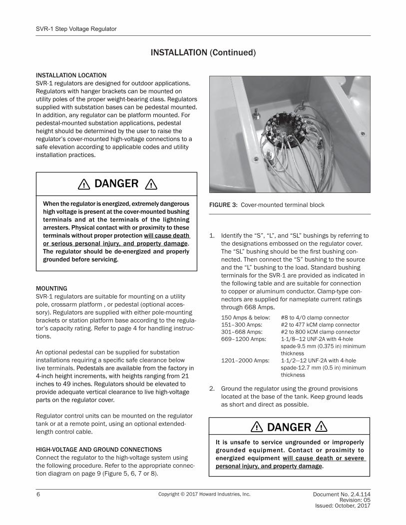
HIGH-VOLTAGE AND GROUND CONNECTIONSConnect the regulator to the high-voltage system using the following procedure. Refer to the appropriate connec-tion diagram on page 9 (Figure 5, 6, 7 or 8).
1. Identify the “S”, “L”, and “SL” bushings by referring to the designations embossed on the regulator cover. The “SL” bushing should be the first bushing con-nected. Then connect the “S” bushing to the source and the “L” bushing to the load. Standard bushing terminals for the SVR-1 are provided as indicated in the following table and are suitable for connection to copper or aluminum conductor. Clamp-type con-nectors are supplied for nameplate current ratings through 668 Amps.150 Amps & below: #8 to 4/0 clamp connector151–300 Amps: #2 to 477 kCM clamp connector301–668 Amps: #2 to 800 kCM clamp connector669–1200 Amps: 1-1/8—12 UNF-2A with 4-hole
spade-9.5 mm (0.375 in) minimum thickness
1201–2000 Amps: 1-1/2—12 UNF-2A with 4-hole spade-12.7 mm (0.5 in) minimum thickness
2. Ground the regulator using the ground provisions located at the base of the tank. Keep ground leads as short and direct as possible.
FIGURE 3: Cover-mounted terminal block
INSTALLATION LOCATIONSVR-1 regulators are designed for outdoor applications. Regulators with hanger brackets can be mounted on utility poles of the proper weight-bearing class. Regulators supplied with substation bases can be pedestal mounted. In addition, any regulator can be platform mounted. For pedestal-mounted substation applications, pedestal height should be determined by the user to raise the regulator’s cover-mounted high-voltage connections to a safe elevation according to applicable codes and utility installation practices.
DANGERIt is unsafe to service ungrounded or improperly grounded equipment. Contact or proximity to energized equipment will cause death or severe personal injury, and property damage.
DANGERWhen the regulator is energized, extremely dangerous high voltage is present at the cover-mounted bushing terminals and at the terminals of the lightning arresters. Physical contact with or proximity to these terminals without proper protection will cause death or serious personal injury, and property damage. The regulator should be de-energized and properly grounded before servicing.
Switch-Pad™ SVR-1 Step Voltage Regulator
Document No. 2.4.114Revision: 05Issued: October, 2017
7Copyright © 2017 Howard Industries, Inc.
INSTALLATION (Continued)
CONTROL CONNECTIONSSVR-1 regulators can be used on several different system voltages. A cover-mounted terminal block (Figure 3) is provided, so that control and fan leads (if present) can be connected as necessary to accommodate the particular system voltage to be regulated.
SVR-1 regulators may be operated at less than the rated voltage as indicated on the nameplate. When operated at less than rated voltage, regulator kVA is reduced, except when operating a 7.62kV regulator at 7.2kV.
In order to properly connect the control leads, it is necessary to refer to the control diagram found on the nameplate (Figure 2). The control diagram will aid in the identification of the appropriate terminal connections. Follow the instructions listed below:
1. Referring to the regulator nameplate diagram, connect the “PS” lead as indicated for the applicable system voltage.
2. For some regulators the nameplate will indicate a connection for the “MS” lead. Connect this lead as indicated.
3. For regulators equipped with cooling fans, connect fan leads as indicated.
BY-PASS SURGE ARRESTEREach SVR-1 regulator is equipped with an appropriately sized by-pass surge arrester connected between the “S” and “L” high-voltage bushing terminals. This by-pass arrester (sometimes refered to as the “series arrester”) is provided to protect the series winding of the regulator from damage due to line surges. The by-pass arrester does not provide complete lightning protection for the regulator. Improved lightning protection can be provided as described below. Refer to the connection diagrams on page 9.
LIGHTNING PROTECTIONLightning protection can be provided by adding appropri-ately sized surge arresters to the “S” and “L” bushing ter-minals. These arresters (called “shunt arresters”) should be mounted on the regulator tank adjacent to both the “S” and “L” bushings using the supplied mounting provi-sions. The top lead of each arrester should be connected to the adjacent bushing terminal. Arrester grounding is achieved through the arrester mounting brackets. Refer to the connection diagrams on page 9.
When supplied by the factory, these arresters are tempo-rarily rotated close to the tank wall to protect them during shipment, and in some cases foam packing material may be used for additional protection. Before placing the regu-lator in service, all packing material must be removed, and the arresters must be rotated to the proper operat-ing position. This can be done by loosening the arrester bracket pivot nut and rotating the arrester, so that it is perpendicular to the tank. The arrester bracket pivot nut must then be re-tightened.
THROUGH FAULTSVR-1 regulators are designed to withstand through-fault currents of 25 times the nameplate rated ONAN current as described in IEEE Standard C57.15-2009.
In order to limit through-fault current to acceptable levels as described above, the user should consider the applica-tion of additional source impedance, bus sectionalizing, or other methods.
50 HERTZ OPERATIONRegulators can be modified at factory for 50 Hertz operation with appropriate derating of voltage. Contact the Howard Industries Regulator Division for information about regulators specifically designed for 50 Hertz. operation.
Document 2.4.114SVR-1 Step Voltage Regulator
Copyright © 2017 Howard Industries, Inc. Document No. 2.4.114Revision: 05
Issued: October, 2017
8
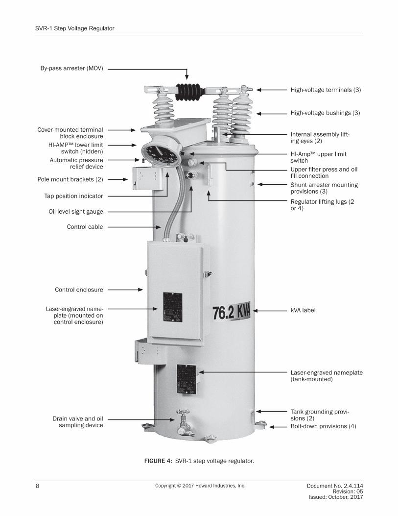
High-voltage bushings (3)
High-voltage terminals (3)
Internal assembly lift-ing eyes (2)
Shunt arrester mounting provisions (3)
Tank grounding provi-sions (2)Bolt-down provisions (4)
Laser-engraved nameplate (tank-mounted)
kVA label
Drain valve and oil sampling device
Laser-engraved name-plate (mounted on control enclosure)
Control enclosure
Control cable
Pole mount brackets (2)
Automatic pressure relief device
Tap position indicator
Cover-mounted terminal block enclosure
Oil level sight gaugeRegulator lifting lugs (2 or 4)
Upper filter press and oil fill connection
By-pass arrester (MOV)
HI-Amp™ upper limit switch
HI-AMP™ lower limit switch (hidden)
FIGURE 4: SVR-1 step voltage regulator.
Switch-Pad™ SVR-1 Step Voltage Regulator
Document No. 2.4.114Revision: 05Issued: October, 2017
9Copyright © 2017 Howard Industries, Inc.
CONNECTION DIAGRAMS
NOTES: 1. Individual bypass and disconnect switches are shown in the diagrams above. Combination switches are available that perform disconnecting and bypass operations sequentially.
2. Do not connect three regulators in a wye configuration on a three-phase, three-wire circuit.
FIGURE 7: Three SVR-1 regulators wye connected in a three-phase four-wire system.
Series Arrester
ShuntArrester
SL
SL SL SLS S
L L
SOUR
CE
LOAD
1 2 3
Disconnects
Bypass Switch1
Bypass Switch1
ABCN
Bypass Switch1
FIGURE 8: Three SVR-1 regulators delta connected in a three-phase three-wire system.2
Bypass Switch1
Bypass Switch1
Bypass Switch1
SOUR
CE ABC LO
AD
ShuntArrester S S S
L L L
SL SL SL
Series Arrester
31 2
FIGURE 5:
Bypass Switch1
Neutral
LOAD
Disconnects
Series Arrester
ShuntArrester
S SL
FIGURE 6: Two SVR-1 regulators in an open delta three-phase system.
Bypass Switch1
Disconnects
ABC
SOUR
CE
Bypass Switch1
1 2
S SLL
SLSL
Series Arrester
LOAD
Disconnects

Document 2.4.114SVR-1 Step Voltage Regulator
Copyright © 2017 Howard Industries, Inc. Document No. 2.4.114Revision: 05
Issued: October, 2017
10
PLACING A REGULATOR IN SERVICE
PROCEDURE FOR PLACING IN SERVICEAfter completing the installation procedure outlined in the previous section, the regulator can be placed into service using the following procedure.
1. Set HI-AMP™ limits, if necessary, using the rotary switches located on either side of the position indicator (Figure 9). The HI-AMP™ feature allows the SVR-1 regulator to be operated above rated load by decreasing the range of operation in 1.25 percent increments. Load current may be increased up to 160 percent of rated current (maximum of 668 Amps) when the regulator is operated at ± 5 percent regulation. Percentages of current ratings for various regulation ranges are as follows:
All that is necessary to adjust the range of regulation anywhere from ±5 percent to ±10 percent is to set the Hi-AMP™ switches to the desired range of regulation is shown. The upper and lower limits need not be the same. (Upper and lower limits of operation can also be implemented with the digital control unit.)
It is not necessary to remove the regulator from service to make this adjustment; however, switches should not be set while the motor is running.
2. Program the control unit as desired. Refer to the manual supplied with the control unit.
3. Make absolutely certain that the regulator is in neutral (0) position. Refer to both the position indicator pointer and the neutral indicator on the control panel. The position indicator must point to “zero,” and the neutral indicator must be continuously illuminated (The control panel can be powered from a 120 Volt external source.)
4. Turn MAIN POWER and MOTOR CONTROL switches to “OFF.”
5. Remove motor fuse.
6. Close the SL disconnect switch (Delta connections only).
7. Sequentially close the source and then the load disconnect switches.
8. Open the bypass switch.9. Visually observe that bypass circuit is open.10. Replace motor fuse.11. Switch MAIN POWER switch to “INTERNAL.”
Voltage Range (%) Current Rating (%)
±10 100
±8.75 110
±7.5 120
135
±5 160
±6.25
FIGURE 9: One of two HI-AMP™ switches located on each side of control position indicator
CAUTIONOperation of the regulator to extreme tap positions can produce a line voltage that is above or below the desired operating limit of the load.
Switch-Pad™ SVR-1 Step Voltage Regulator
Document No. 2.4.114Revision: 05Issued: October, 2017
11Copyright © 2017 Howard Industries, Inc.
PLACING A REGULATOR IN SERVICE (Continued)
CHECKING FOR PROPER OPERATIONRefer to the control unit instruction manual and use the following procedure to check for proper regulator operation. (Switch designations referenced below are applicable to the HI/ICMI control.)
1. Set the MOTOR CONTROL AUTO/MANUAL switch to “MANUAL”.
2. Holding the the MOTOR CONTROL RAISE/LOWER switch in the “LOWER” position, run the regulator in the lower direction until the control panel LOW BAND indicator illuminates.
3. Set the MOTOR CONTROL AUTO/MANUAL switch to the “AUTO” position. After a time delay, the regulator will automatically return to an IN-BAND condition. The control panel IN-BAND indicator will illuminate.
4. Set the MOTOR CONTROL AUTO/MANUAL switch to the “MANUAL” position.
5. Holding the MOTOR CONTROL RAISE/LOWER switch in the “RAISE” position, run the regulator in the raise direction until the control panel HIGH BAND indicator illuminates.
6. Set the MOTOR CONTROL AUTO/MANUAL switch to the “AUTO” position, After a time delay, the regulator will automatically return to an IN-BAND condition. The control panel IN-BAND indicator will illuminate.
Document 2.4.114SVR-1 Step Voltage Regulator
Copyright © 2017 Howard Industries, Inc. Document No. 2.4.114Revision: 05
Issued: October, 2017
12
REMOVING A REGULATOR FROM SERVICE
The following procedure should be used to remove a regulator from service. For additional information refer to the manual supplied with the control unit (Switch desig-nations referenced below are applicable to the HI/ICMI control.).1. Set MOTOR CONTROL AUTO/MANUAL switch to
MANUAL position.2. Using the MOTOR CONTROL RAISE/LOWER switch,
run the regulator tap changer to the neutral position as indicated by the tap position indicator dial.
3. Confirm that the regulator is in the neutral position. The tap position indicator should point to “0”, and the NEUTRAL LIGHT on the control panel should be continuously illuminated. Do not proceed unless both the tap position indicator dial and the NEUTRAL LIGHT indicate that the regulator is in the neutral position.
4. Place MOTOR CONTROL switch in the “OFF” position.5. Remove the MOTOR fuse.6. Place the MAIN POWER switch in the “OFF” position.6. Close the bypass switch*.7. Open the source “S” disconnect switch*.8. Open the load “L” disconnect switch*.
9. Open the source/load “SL” disconnect switch (delta connections only).
*Note: A combination by-pass/disconnect switch can be used instead of separate switches to by-pass and discon-nect in a sequential operation.
RETURNING A REGULATOR TO SERVICEAfter removing a regulator from service, it can be safely returned to service according to the procedure discussed on pages 10 and 11.
DANGERA regulator must never be by-passed unless it has first been placed in the neutral position. By-passing a regulator not in the neutral position will cause an internal short circuit and will cause death or serious personal injury, and property damage
Switch-Pad™ SVR-1 Step Voltage Regulator
Document No. 2.4.114Revision: 05Issued: October, 2017
13Copyright © 2017 Howard Industries, Inc.
MAINTENANCE
OPERATIONAL CHECKSPeriodic operational checks should be performed to verify proper operation of the control unit, the tap changer mechanism, and the HI-AMP™ limiters. These checks can be made while the regulator is in service. Output voltage should be monitored during the procedure using a voltmeter connected to the control unit’s test terminals. The control unit manual should be referenced for further information.
The following procedure should be followed to check operation of the control unit, the tap changer mechanism, and the HI-AMP™ limiters.1. Referring to control panel indicators, make sure
the regulator is “IN-BAND” and that line drop compensation is set to zero (Return line drop compensation to the proper setting after completing the checklist.).
2. Verify that the voltmeter indicates a voltage within one-half of the bandwidth tolerance.
3. Place the AUTO/MANUAL switch in the “MANUAL” position.
4. Using the RAISE/LOWER switch run the tap changer several steps in either direction, until control panel indicates an out-of-band condition.
5. Return the AUTO/MANUAL switch to the “AUTO” position. After a time delay, the control will automatically return the regulator to an in-band condition.
6. Repeat steps 3 through 5, but in the opposite direction.
7. Check operation of the HI-AMP™ limit switches (located on the either side control position indicator) by attempting to run the regulator beyond the limits set by the switches. The limit switches should stop tap changer operation at the corresponding tap position.
GENERAL INSTRUCTIONSSVR-1 step voltage regulators are designed for long life and trouble-free operation. Periodic inspection and maintenance will prolong life and minimize the likelihood of service interruptions. Proper operation can be checked without removing the regulator from service. Follow the procedures in this section to perform in-service inspection and maintenance.
The operational life of a regulator will depend somewhat on the application and environment; hence, the frequency and scope of maintenance should be tailored to a regulators specific situation. Regulators subjected to higher loads and/or more frequent tap changer operations should be inspected more frequently than regulators exposed to lighter duty.
In certain situations it might be advisable to periodically remove a regulator from service for thorough testing and internal inspection. In addition, anytime an operational regulator is removed from service for any reason, the opportunity should be used for testing and a thorough inspection, following the procedure in the pre-installation checklist (page 5) at a minimum.
The procedures outlined below are intended to verify proper operation of the control unit, tap changer mechanism, HI-AMP™ limiters, and cooling fans (if present), and to check for tap changer contact wear and the condition of the insulating fluid. Other checks may be advisable for certain regulators, particularly those serving special applications or operating in severe environments. The user should contact Howard Industries Regulator Division for additional information.
CAUTIONOperation of the regulator to extreme tap positions can produce a line voltage that is above or below the desired operating limit of the load, causing property damage.
WARNINGThese maintenance instructions should be followed to ensure proper and safe regulator operation. Tampering or maintenance by unqualified personnel can degrade operational performance and can cause unsafe conditions that can cause death, serious personal injury, or property damage.
Document 2.4.114SVR-1 Step Voltage Regulator
Copyright © 2017 Howard Industries, Inc. Document No. 2.4.114Revision: 05
Issued: October, 2017
14
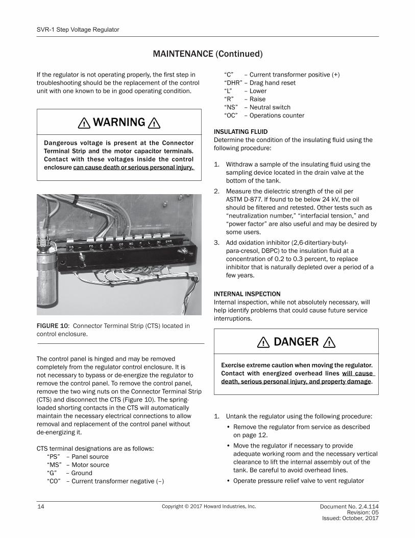
The control panel is hinged and may be removed completely from the regulator control enclosure. It is not necessary to bypass or de-energize the regulator to remove the control panel. To remove the control panel, remove the two wing nuts on the Connector Terminal Strip (CTS) and disconnect the CTS (Figure 10). The spring-loaded shorting contacts in the CTS will automatically maintain the necessary electrical connections to allow removal and replacement of the control panel without de-energizing it.
CTS terminal designations are as follows: “PS” – Panel source “MS” – Motor source “G” – Ground “CO” – Current transformer negative (–)
“C” – Current transformer positive (+) “DHR” – Drag hand reset “L” – Lower “R” – Raise “NS” – Neutral switch “OC” – Operations counter
INSULATING FLUIDDetermine the condition of the insulating fluid using the following procedure:
1. Withdraw a sample of the insulating fluid using the sampling device located in the drain valve at the bottom of the tank.
2. Measure the dielectric strength of the oil per ASTM D-877. If found to be below 24 kV, the oil should be filtered and retested. Other tests such as “neutralization number,” “interfacial tension,” and “power factor” are also useful and may be desired by some users.
3. Add oxidation inhibitor (2,6-ditertiary-butyl-para-cresol, DBPC) to the insulation fluid at a concentration of 0.2 to 0.3 percent, to replace inhibitor that is naturally depleted over a period of a few years.
INTERNAL INSPECTIONInternal inspection, while not absolutely necessary, will help identify problems that could cause future service interruptions.
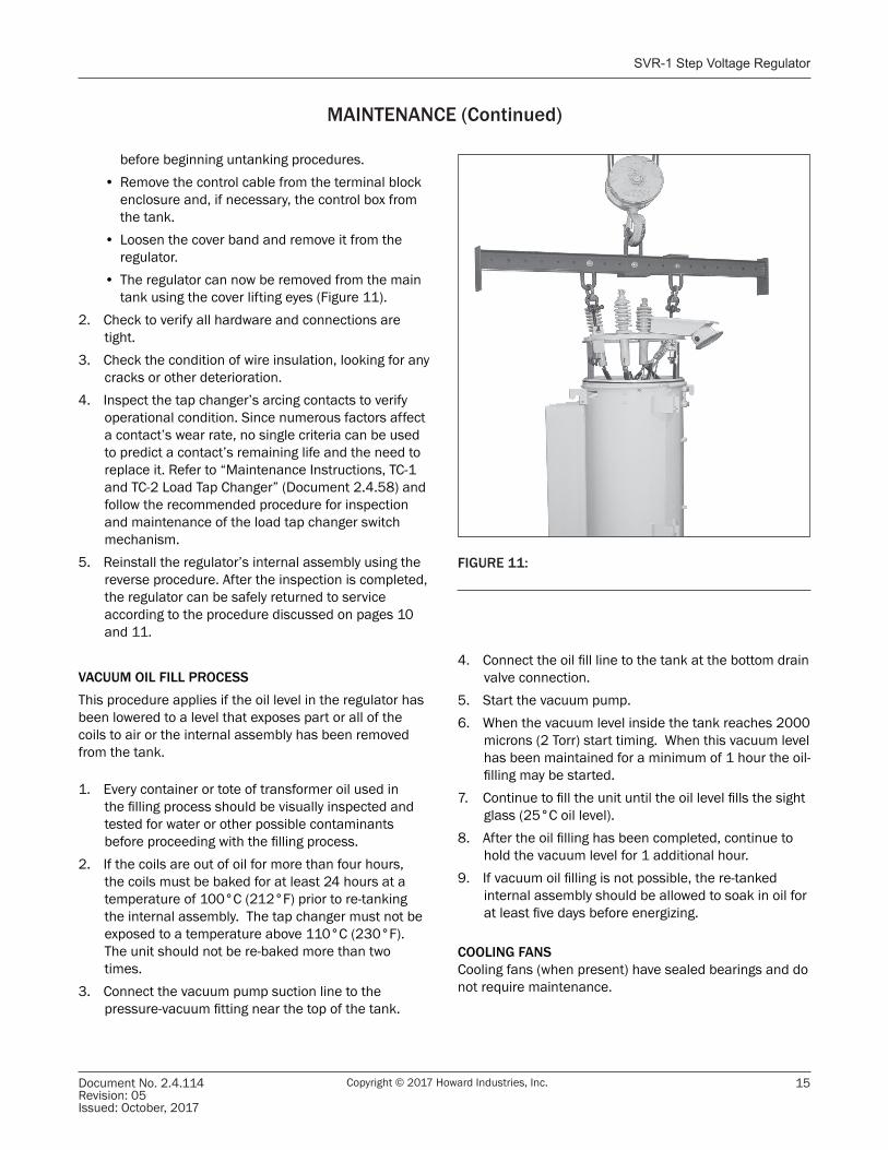
1. Untank the regulator using the following procedure:• Remove the regulator from service as described
on page 12. • Move the regulator if necessary to provide
adequate working room and the necessary vertical clearance to lift the internal assembly out of the tank. Be careful to avoid overhead lines.
• Operate pressure relief valve to vent regulator
If the regulator is not operating properly, the first step in troubleshooting should be the replacement of the control unit with one known to be in good operating condition.
MAINTENANCE (Continued)
WARNINGDangerous voltage is present at the Connector Terminal Strip and the motor capacitor terminals. Contact with these voltages inside the control enclosure can cause death or serious personal injury.
FIGURE 10: Connector Terminal Strip (CTS) located in control enclosure.
DANGER
Exercise extreme caution when moving the regulator. Contact with energized overhead lines will cause death, serious personal injury, and property damage.
Switch-Pad™ SVR-1 Step Voltage Regulator
Document No. 2.4.114Revision: 05Issued: October, 2017
15Copyright © 2017 Howard Industries, Inc.
before beginning untanking procedures.• Remove the control cable from the terminal block
enclosure and, if necessary, the control box from the tank.
• Loosen the cover band and remove it from the regulator.
• The regulator can now be removed from the main tank using the cover lifting eyes (Figure 11).
2. Check to verify all hardware and connections are tight.
3. Check the condition of wire insulation, looking for any cracks or other deterioration.
4. Inspect the tap changer’s arcing contacts to verify operational condition. Since numerous factors affect a contact’s wear rate, no single criteria can be used to predict a contact’s remaining life and the need to replace it. Refer to “Maintenance Instructions, TC-1 and TC-2 Load Tap Changer” (Document 2.4.58) and follow the recommended procedure for inspection and maintenance of the load tap changer switch mechanism.
5. Reinstall the regulator’s internal assembly using the reverse procedure. After the inspection is completed, the regulator can be safely returned to service according to the procedure discussed on pages 10 and 11.
VACUUM OIL FILL PROCESSThis procedure applies if the oil level in the regulator has been lowered to a level that exposes part or all of the coils to air or the internal assembly has been removed from the tank.
1. Every container or tote of transformer oil used in the filling process should be visually inspected and tested for water or other possible contaminants before proceeding with the filling process.
2. If the coils are out of oil for more than four hours, the coils must be baked for at least 24 hours at a temperature of 100°C (212°F) prior to re-tanking the internal assembly. The tap changer must not be exposed to a temperature above 110°C (230°F). The unit should not be re-baked more than two times.
3. Connect the vacuum pump suction line to the pressure-vacuum fitting near the top of the tank.
MAINTENANCE (Continued)
FIGURE 11:
4. Connect the oil fill line to the tank at the bottom drain valve connection.
5. Start the vacuum pump.6. When the vacuum level inside the tank reaches 2000
microns (2 Torr) start timing. When this vacuum level has been maintained for a minimum of 1 hour the oil-filling may be started.
7. Continue to fill the unit until the oil level fills the sight glass (25°C oil level).
8. After the oil filling has been completed, continue to hold the vacuum level for 1 additional hour.
9. If vacuum oil filling is not possible, the re-tanked internal assembly should be allowed to soak in oil for at least five days before energizing.
COOLING FANSCooling fans (when present) have sealed bearings and do not require maintenance.
Document 2.4.114SVR-1 Step Voltage Regulator
Copyright © 2017 Howard Industries, Inc. Document No. 2.4.114Revision: 05
Issued: October, 2017
16
Additional Maintenance InstructionsFeatures and accessory devices discussed herein may not be present in all regulators. Some features or accessory devices may be present on a regulator, but not discussed in these instructions. Howard Industries does not represent that these instructions are complete, sufficient, accurate or useful for all circumstances. Questions regarding installation, operation, and maintenance should be directed to the Howard Industries Transformer Division, particularly when encountering unusual or special circumstances not sufficiently covered by these instructions.
Repair PartsRepair parts can be ordered from the Howard Industries Transformer Division. A description of the part and the regulator serial number will be required to ensure that the correct part has been ordered.
Warranty ClaimsThe Howard Industries Transformer Division should be notified immediately when problems are discovered during the warranty period. All warranty repairs must be made or approved by the Howard Industries Transformer Division.
Regulator DisposalComply with all local, state and federal regulations when disposing of any insulating fluid. Fluid type and volume can be determined by referring to the regulator nameplate. Contact Howard Industries to obtain the appropriate fluid Safety Data Sheet (SDS). The SDS identifies fluid composition and properties, and describes important safety, handling and storage, ecological, regulatory, disposal and other pertinent information.
WARNINGImproper disposal of a regulator could result in personal injury or death and could be hazardous to the environment.
Before the regulator tank can be safely cut with a grinder or torch, any potentially explosive gasses must be removed from the tank interior. This can be done by first operating the pressure relief device to slowly bring the tank interior to atmospheric pressure, removing the regulator cover or hand-hole cover, and then completely purging the interior with pure air or an inert gas such as nitrogen.
To avoid death from suffocation, never allow anyone to enter the interior of a regulator tank unless an analysis of the air in the tank shows at least 19.5% oxygen content. Whenever anyone is in the tank a person should be stationed at the manhole outside the tank to ensure the safety of the person inside.
Switch-Pad™ SVR-1 Step Voltage Regulator
Document No. 2.4.114Revision: 05Issued: October, 2017
17Copyright © 2017 Howard Industries, Inc.
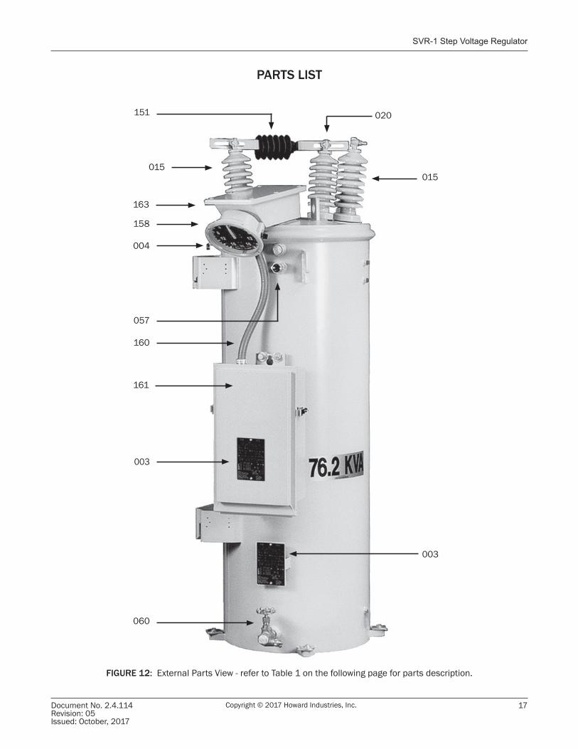
PARTS LIST
FIGURE 12: External Parts View - refer to Table 1 on the following page for parts description.
015
020
003
060
003
160
004
015
057
151
158
163
161
Document 2.4.114SVR-1 Step Voltage Regulator
Copyright © 2017 Howard Industries, Inc. Document No. 2.4.114Revision: 05
Issued: October, 2017
18
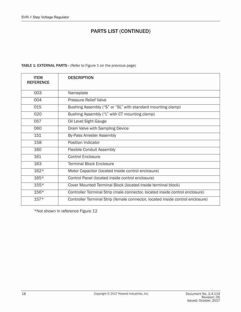
PARTS LIST (CONTINUED)
ITEM DESCRIPTION REFERENCE
003 Nameplate
004 Pressure Relief Valve
015 Bushing Assembly (“S” or “SL” with standard mounting clamp)
020 Bushing Assembly (“L” with CT mounting clamp)
057 Oil Level Sight Gauge
060 Drain Valve with Sampling Device
151 By-Pass Arrester Assembly
158 Position Indicator
160 Flexible Conduit Assembly
161 Control Enclosure
163 Terminal Block Enclosure
162* Motor Capacitor (located inside control enclosure)
165* Control Panel (located inside control enclosure)
155* Cover Mounted Terminal Block (located inside terminal block)
156* Controller Terminal Strip (male connector, located inside control enclosure)
157* Controller Terminal Strip (female connector, located inside control enclosure)
*Not shown in reference Figure 12
TABLE 1: EXTERNAL PARTS - (Refer to Figure 1 on the previous page)
Switch-Pad™ SVR-1 Step Voltage Regulator
Document No. 2.4.114Revision: 05Issued: October, 2017
19Copyright © 2017 Howard Industries, Inc.
NOTES
Document 2.4.114SVR-1 Step Voltage Regulator
Copyright © 2017 Howard Industries, Inc. Document No. 2.4.114Revision: 05
Issued: October, 2017
20
SVR-1 Step Voltage RegulatorInstallation, Operation, and Maintenance Instructions
Document No. 2.4.114, Revision 5, October 2017Copyright © 2017 Howard Industries, Inc.
Laurel, MississippiTelephone: 601-425-3151
Fax: 601-649-8090Web howardtransformers.com


![[PPT]Three-Phase Inverters - Welcome - Faculty Pages - … · Web viewThree-Phase Inverters Consider three single-phase inverters in parallel, driven 120 apart. Three-Phase Inverter](https://img.pdfslide.us/doc/110x75/5b08de6f7f8b9a520e8d510f/pptthree-phase-inverters-welcome-faculty-pages-viewthree-phase-inverters.jpg)