Embed Size (px)
Citation preview
201 Hancock Ave. Bridgeport, CT 06605, USA | 203.366.5400
email [email protected] | www.gesswein.com Page 1
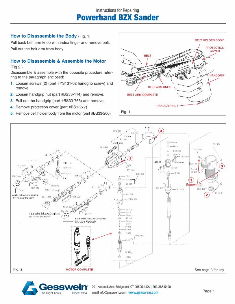
How to Disassemble the Body (Fig. 1)
Pull back belt arm knob with index finger and remove belt.
Pull out the belt arm from body.
How to Disassemble & Assemble the Motor(Fig 2.) Disassemble & assemble with the opposite procedure refer-ring to the paragraph enclosed:
1. Loosen screws (2) (part #YS131-02 handgrip screw) and remove.
2. Loosen handgrip nut (part #BS33-114) and remove.
3. Pull out the handgrip (part #BS33-766) and remove.
4. Remove protection cover (part #BS1-277)
5. Remove belt holder body from the motor (part #BS33-200)
Instructions for Repairing
Powerhand BZX Sander
BELT
BELT ARM COMPLETE
BELT HOLDER BODY
PROTECTIONCOVER
HANDGRIP NUT
HANDGRIP
BELT ARM KNOB
Fig. 1
4
5
2
3
MOTOR COMPLETE
1Screws (2)
Fig. 2 See page 3 for key
BELT
BELT ARM COMPLETE
BELT HOLDER BODY
PROTECTIONCOVER
HANDGRIP NUT
HANDGRIP
BELT ARM KNOB

201 Hancock Ave. Bridgeport, CT 06605, USA | 203.366.5400
email [email protected] | www.gesswein.com Page 2
Changing Arm Pads (Fig. 3)Remove the worn pad from the belt arm. Replace with a new support arm pad by remov-ing the self adhesive backing and place in the same position.
Changing Belt Arm Pulleys (Fig. 3)Unfasten 2 screws located on top of the belt arm. Spread the two plates sufficiently apart to remove the defective pulley. Replace new pul-ley and secure with screws.)
Changing Carbon Brushes (Fig. 4)Loosen 2 screws (YSR21-101) and remove both sides. Pull the motor cap out (BS33-214)Loosen 2 screws on both sides of the carbon brushes and remove.
Inspection Of Carbon Brushes (Fig. 4)Check carefully if carbon brushes are worn out or not. Replace new carbon brushes if necessary.
Changing Ball Bearings (Fig. 4)Loosen 2 screws and remove brush side lid (part #UM-20-202)
1. Pull the armature out.
2. Remove ball bearing (1040ZZ) from the rear of armature. Inspect ball bearing and replace
if necessary.
2. Front ball bearing: Remove the C type clip ring (KC-041) Remove wave washer (KW-041) Remove spacer (KS-091) Remove ball bearing (1350ZZ) Inspect front bearing and replace
if necessary.
Instructions for Repairing Powerhand BZX Sander
Arm Pad 4mm
Pulley
Arm Pad 7mm
Screws (2)
Fig. 3
MOTOR COMPLETE
Armature
Ball Bearing (1030ZZ)
Ball Bearing (1340ZZ)
Motor Cap
Screws (2)
Brush Side Lid
Carbon Brushes
Fig. 4
Pulley

201 Hancock Ave. Bridgeport, CT 06605, USA | 203.366.5400
email [email protected] | www.gesswein.com Page 3
Part# Item# DescriptionBS1-100-1 510-0494 Belt Arm Completed (4mm)BS1-100-2 510-0496 Belt Arm Completed (7mm)BS1-100-3 510-0495 Belt Arm Completed (45°)BS1-130 896-0183 Belt Arm Pulley (4 mm)BS1-140A 896-0350 Belt Arm Pulley (7 mm)BS1-272 896-0185 Support Arm Pad (4 mm)BS1-273 896-0186 Support Arm Pad (7 mm)BS33-258 896-0187 Support Arm Pad (45°)BS1-276 896-0188 Dust Proof CushionS-5 896-0189 O-Type Rubber RingYSF21-120 896-0190 Pan Headed ScrewYSF21-113 896-0191 Pan Headed ScrewBS33-270 896-0192 Guide Pulley CompletedS-9 896-0193 O-Type Rubber RingBS33-257A 896-0194 Pulley CoverYSM21-101 896-0195 Countersunk Head ScrewBS33-200 896-0196 Belt Holder Body CompletedBS33-200A 896-0197 Belt Holder BodyBS1-203B 896-0198 Minibelt Sander Name PlateBS3-289 896-0200 BZX Name PlateBS1-263 896-0200 Spring Base
Part# Item# DescriptionBS1-264 896-0201 Screw LidKB-099 896-0202 Coil SpringBS1-277 896-0203 Protection CoverBS33-107 896-0352 Motor CompletedBS33-260 896-035 Driving Pulley CompletedBS3-265 896-0206 Driving Pulley OnlyBS3-266 896-0207 Driving Rubber RingETW-2 896-0156 E-Type Clip RingBS33-311 896-0354 Motor HousingON15-301 896-0160 O-Type Rubber RingKS-139 896-0161 Metal spacerKS-632A 896-0163 Metal spacerKW-130B 896-0355 Wave WasherKS-045 896-0165 Fiber SpacerKC-041 896-0209 C-Type Clip RingKW-041 896-0167 Wave WasherKS-091 896-0210 SpacerYSF21-103 896-0002 Countersunk Head ScrewKA20-107 896-0356 ArmatureKF-220 896-0357 Dust Proof CollarKF-210 896-0011 Dust Proof Collar
Part# Item# Description1340ZZ 510-3094 Ball Bearing1030ZZ 510-3073 Ball BearingS-10 896-0012 O-Type Rubber RingKS-101 896-0013 Teflon SpacerHE10A-203 896-0014 Rear LidPKE60-103A 510-0161 Carbon Brush ( 2 pcs)UM20-202 896-0321 Brush Side LidYSP23-103 896-0017 Pan Headed ScrewON10-204 896-0015 O-type Rubber RingBS33-214 896-0358 Motor CapKE-126 896-0018 (+) Terminal PlateKE-127 896-0019 (-) Terminal PlateKE-209 510-0171 Motor Cord with PlugYSR21-101 896-0359 Countersunk Head ScrewBS33-766 896-0360 HandgripBS33-114 896-0361 Handgrip Retaining NutBS33-209 — Grounding PinYSR31-102 896-0119 Handgrip Locking ScrewKU-245 896-0122 Gesswein Name PlateRE1-204F 896-0121 DC30V Name Plate
Changing & Inspection Of Armature (Fig. 5)
Check carefully if the commutator of the armature is worn out. Replace armature if necessary. Changing & Inspection Of Driving Pulley Complete (Fig. 5)
Remove the E-ring (ETW-2). Then remove Driving Pulley Complete (BS-33-260) out from motor by turning to counter clockwise direction. Inspect the Driving Pulley and replace if necessary.
Armature
Cummulator of the Armature
E-ring
Driving Pulley Complete
8914
033/
5102
131/
0119
Instructions for Repairing Powerhand BZX Sander
Fig. 5