Embed Size (px)
Citation preview
IS-FS-200-W
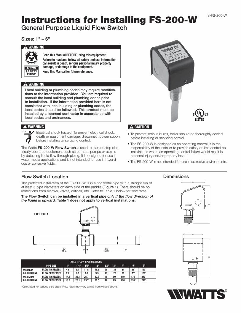
Instructions for Installing FS-200-WGeneral Purpose Liquid Flow Switch
Sizes: 1" – 6"
The Watts FS-200-W Flow Switch is used to start or stop elec-trically operated equipment such as burners, pumps or alarms by detecting liquid flow through piping. It is designed for use in water media applications and is not intended for use in hazard-ous or corrosive fluids.
WARNING!
Read this Manual BEFORE using this equipment.Failure to read and follow all safety and use information can result in death, serious personal injury, property damage, or damage to the equipment.Keep this Manual for future reference.
Flow Switch LocationThe preferred installation of the FS-200-W is in a horizontal pipe with a straight run of at least 5 pipe diameters on each side of the paddle (Figure 1). There should be no restrictions from elbows, valves, orifices, etc. Refer to Table 1 below for flow rates.
The Flow Switch can be installed in a vertical pipe only if the flow direction of the liquid is upward. Table 1 does not apply to vertical installations.
WARNING!Electrical shock hazard. To prevent electrical shock, death or equipment damage, disconnect power supply before installing or servicing control.
Local building or plumbing codes may require modifica-tions to the information provided. You are required to consult the local building and plumbing codes prior to installation. If the information provided here is not consistent with local building or plumbing codes, the local codes should be followed. This product must be installed by a licensed contractor in accordance with local codes and ordinances.
WARNING!
CAUTION!
• To prevent serious burns, boiler should be thoroughly cooled before installing or servicing control.
• The FS-200-W is designed as an operating control. It is the responsibility of the installer to provide safety or limit control on installations where an operating control failure would result in personal injury and/or property loss.
• The FS-200-W is not intended for use in explosive environments.
FIGURE 1
Dimensions
TABLE 1 FLOW SPECIFICATIONS PIPE SIzE 1" 11⁄4" 11⁄2" 2" 21⁄2" 3" FLOW INCREASES 4.5 8.1 11.8 16.5 25 33 51 85* 120* FLOW DECREASES 2.2 6.8 7.6 9.3 19 22 38 75* 100* FLOW INCREASES 14.8 22.1 25.7 32.3 75 90* 110* 170* 240*
FLOW DECREASES 13.8 20.1 23.7 30.5 72 85* 100* 155* 220*
*Calculated for various pipe sizes. Flow rates may vary ±10% from values above.
MINIMuMADJuSTMENTMAxIMuMADJuSTMENT
4" 5" 6"
Limited Warranty: Watts Regulator Co. (the “Company”) warrants each product to be free from defects in material and workmanship under normal usage for a period of one year from the date of original shipment. In the event of such defects within the warranty period, the Company will, at its option, replace or recondition the product without charge. THE WARRANTY SET FORTH HEREIN IS GIVEN ExPRESSLY AND IS THE ONLY WARRANTY GIVEN BY THE COMPANY WITH RESPECT TO THE PRODuCT. THE COMPANY MAKES NO OTHER WARRANTIES, ExPRESS OR IMPLIED. THE COMPANY HEREBY SPECIFICALLY DISCLAIMS ALL OTHER WARRANTIES, ExPRESS OR IMPLIED, INCLuDING BuT NOT LIMITED TO THE IMPLIED WARRANTIES OF MERCHANTABILITY AND FITNESS FOR A PARTICuLAR PuRPOSE.The remedy described in the first paragraph of this warranty shall constitute the sole and exclusive remedy for breach of warranty, and the Company shall not be responsible for any incidental, special or consequential damages, including without limitation, lost profits or the cost of repairing or replacing other property which is damaged if this product does not work properly, other costs resulting from labor charges, delays, vandalism, negligence, fouling caused by foreign material, damage from adverse water conditions, chemical, or any other circumstances over which the Company has no control. This warranty shall be invalidated by any abuse, misuse, misapplication, improper installation or improper maintenance or alteration of the product. Some States do not allow limitations on how long an implied warranty lasts, and some States do not allow the exclusion or limitation of incidental or consequential damages. Therefore the above limitations may not apply to you. This Limited Warranty gives you specific legal rights, and you may have other rights that vary from State to State. You should consult applicable state laws to determine your rights. SO FAR AS IS CONSISTENT WITH APPLICABLE STATE LAW, ANY IMPLIED WARRANTIES THAT MAY NOT BE DISCLAIMED, INCLuDING THE IMPLIED WARRANTIES OF MERCHANTABILITY AND FITNESS FOR A PARTICuLAR PuRPOSE, ARE LIMITED IN DuRATION TO ONE YEAR FROM THE DATE OF ORIGINAL SHIPMENT.
WARNING: This product contains chemicals known to the State of California to cause cancer and birth defects or other reproductive harm.For more information: www.watts.com/prop65
IS-FS-200-W 1517 EDP#2915183 © 2015 Watts
USA: Tel: (978) 689-6066 • Fax: (978) 975-8350 • Watts.comCanada: Tel: (905) 332-4090 • Fax: (905) 332-7068 • Watts.ca
Latin America: Tel: (52) 81-1001-8600 • Fax: (52) 81-8000-7091 • Watts.com
A Watts Water Technologies Company
Pressure — TemperatureMaximum Service Pressure: 160 psiMaximum Temperature: 250°FEnclosure: NEMA type 1 (for indoor use only).
Formed sheet metal construction. Powder coated cover, zinc plated chassis, brass body. Not for use in hazardous locations.
Contacts: SPDT switch 7.4 FLA, 44.4 LRA@120VAC Motor Duty
Pilot Duty Rating: 125V@120/240VACAmbient Temp. Range: 32°F-176°F (0°C-80°C) Media Temp. Range: 32°F-250°F (0°C-121°C)Pipe Connection: 1"NPT - BrassConduit Access: 2 openings for 1/2" conduitUsage: 1" to 6" pipe sizes
(see Flow Chart - Table 1)
Installation InstructionsTrimming the Paddles
1. The stainless steel paddles (set of 4 supplied) must be trimmed to the appropriate length for the pipe diameter being used. Use the template at the right of this page as a cutting guide. Follow the curve indicated as closely as pos-sible. Standard shears or tin snips can be used.
Stacking the Paddles
2. After trimming, the paddles must be stacked as shown in Figure 2 and then screwed onto the stem of the flow switch.
The correct orientation of the paddles to the flow of the fluid is essential.
Installing the Tee
3. The Flow Switch must be installed in a 1" NPT threaded pipe fitting. If a reducing bushing or welded fitting is required, the length must be kept to a minimum to insure that the paddle can move freely in the run of the pipe without coming in contact with the bush-ing or fitting. Tighten the Flow Switch with a 15/8" box wrench or adjustable wrench applied to the brass nut only. Do not tighten by grasping the enclosure. Allow a 13/4" space from the bottom of the enclosure to the top of the tee (Figure 3) and be sure that the arrow on the side of the enclosure is in the direction of the flow.
The paddle must not touch the inside wall of the opposite side of the pipe. If there is any contact, additional trimming is required.
Wiring
4. ENERGIZE CIRCUIT UPON FLOW
Flow Switch will activate load (alarm, light, relay, motor starter, etc.) when flow occurs.
ENERGIZE CIRCUIT UPON NO FLOW
Flow Switch will activate load (alarm, light, relay, motor starter, etc.) when no flow occurs.
Adjusting Sensitivity
5. To INCREASE sensitivity (switch acti-vates at a lower flow rate), turn the adjustment screw counter-clockwise. To DECREASE sensitivity (switch activates at a higher flow rate), turn the adjustment screw clockwise.
NOTICE
NOTICE
FIGURE 2
FIGURE 3
FIGURE 4
COMMON (COM)
FLOW OPENS CIRCUIT (NC)
FLOW CLOSES CIRCUIT (NO)
IS-FS-200-W_FR-CA
Instructions d'installation du FS-200-WCapteur de débit de liquide à usage général
Tailles : 1 po - 6 po
Le capteur de débit FS-200-W de Watts est utilisé pour démarrer ou arrêter des équipements à commande électrique, comme des brûleurs, des pompes ou des alarmes, en détectant le débit de liquide qui circule dans la tuyauterie. Il est destiné à être utilisé dans des applications impliquant de l'eau et ne doit pas être utilisé avec des liquides dangereux ou corrosifs.
AVERTISSEMENT!
Lisez ce manuel AVANT d’utiliser cet équipement.Le non-respect de cette instruction ou des informations relatives à la sécurité et à l'utilisation risque de provoquer des blessures, des dégâts matériels et des dommages à l'équipement.Conservez ce manuel pour référence ultérieure.
LA SÉCURITÉ
AVANTTOUT
Emplacement du capteur de débitL'installation recommandée du FS-200-W est à l'intérieur d'un tuyau horizontal droit d'une longueur d'au moins cinq fois le diamètre du tuyau de chaque côté de la palette (Figure 1). Il ne doit y avoir aucune restriction due à des obstacles comme des coudes, soupapes, orifices, etc. Reportez-vous au Tableau 1 ci-dessous pour connaître les débits.
Le capteur de débit peut être installé dans un tuyau vertical uniquement si le liquide s'écoule vers le haut. Le Tableau 1 ne concerne pas les applications verticales.
AVERTISSEMENT!Risque de décharge électrique. Pour éviter tout risque de décharge électrique, décès ou endommagement de l'équipement, débranchez le bloc d'alimentation avant l'installation ou l'entretien de la commande.
Les codes du bâtiment ou de plomberie locaux peuvent commander des modifications à l’information fournie. Vous êtes tenu de consulter les codes du bâtiment ou de plomberie locaux avant l’installation. Si les informations fournies ne sont pas compatibles avec les codes du bâtiment ou de plomberie locaux, les codes locaux prévalent. Ce produit doit être installé par un entrepreneur certifié et respecter les codes et ordonnances locaux.
AVERTISSEMENT!
MISE EN GARDE!• Pour éviter les brûlures graves, la chaudière doit être entièrement
refroidie avant l'installation ou l'entretien de la commande.
• Le FS-200-W est conçu comme une commande de fonctionnement. L'installateur a la responsabilité de fournir un contrôle de sécurité ou de limite sur les installations sur lesquelles une défaillance de la commande de fonctionnement risquerait d'engendrer des blessures corporelles et/ou des dégâts matériels.
• Le FS-200-W n'est pas destiné à être utilisé dans des environnements explosifs.
5 x DMIN.
5 x DMIN.
D
FIGURE 1
Dimensions3,8
5,9
3,2
5,9
TABLEAU 1 CARACTÉRISTIQUES DE DÉBIT TAILLE DU TUyAU 1 po 11⁄4 po 11⁄2 po 2 po 21⁄2 po 3 po AUGMENTATION DU DÉBIT 4,5 8,1 11,8 16,5 25 33 51 85* 120* RÉDUCTION DU DÉBIT 2,2 6,8 7,6 9,3 19 22 38 75* 100* AUGMENTATION DU DÉBIT 14,8 22,1 25,7 32,3 75 90* 110* 170* 240*
RÉDUCTION DU DÉBIT 13,8 20,1 23,7 30,5 72 85* 100* 155* 220*
*Calculé pour différentes tailles de tuyaux. Les débits peuvent varier de ±10 % par rapport aux valeurs ci-dessus.
RÉGLAGE MINIMUMRÉGLAGE MAxIMUM
4 po 5 po 6 po
Garantie limitée : Watts Regulator Co. (la « Société ») garantit que chacun de ses produits est exempt de vice de matériau et de fabrication dans des conditions normales d’utilisation, pour une période d’un an à compter de la date d’expédition d’origine. Dans l’éventualité où de tels vices se manifesteraient pendant la période de garantie, la Société, à sa discrétion, remplacera ou reconditionnera le produit sans frais. LA PRÉSENTE GARANTIE EST ExPRESSE ET REPRÉSENTE LA SEULE GARANTIE OFFERTE PAR LA SOCIÉTÉ POUR CE PRODUIT. LA SOCIÉTÉ N’OFFRE AUCUNE AUTRE GARANTIE, ExPRESSE OU TACITE. PAR LA PRÉSENTE, LA SOCIÉTÉ REJETTE SPÉCIFIQUEMENT TOUTE AUTRE GARANTIE, ExPRESSE OU TACITE, NOTAMMENT TOUTE GARANTIE TACITE DE QUALITÉ MARCHANDE OU D’ADAPTATION À UN BUT PARTICULIER.Le recours décrit dans le premier paragraphe de cette garantie constitue le seul recours à toute violation de la présente garantie. La Société ne saurait être tenue responsable de tout dommage accessoire, spécial ou indirect, y compris, sans limitation : la perte de profits ou le coût afférent à la réparation ou au remplacement d’autres biens qui seraient endommagés par suite du fonctionnement incorrect dudit produit; d’autres coûts résultant de frais de main-d’oeuvre, de retards, de vandalisme, de négligence, d’une obstruction causée par des corps étrangers, de dommages causés par une eau impropre, des produits chimiques ou par tout autre événement échappant au contrôle de la Société. La présente garantie est déclarée nulle et non avenue en cas d’usage abusif ou incorrect, d’application, d’installation ou d’entretien incorrects ou de modification du produit. Certains États n’autorisent pas les limitations de durée d’une garantie tacite ou l’exclusion ou la limitation des dommages accessoires ou indirects. Les limitations susmentionnées peuvent donc ne pas s’appliquer à vous. Cette garantie limitée vous donne des droits spécifiques et il se peut que vous ayez aussi d’autres droits qui varient d’un État à l’autre. Veuillez vous référer aux lois applicables de l’État pour déterminer vos droits en la matière. DANS LA MESURE PERMISE PAR LA LOI APPLICABLE DE L’ÉTAT, TOUTES LES GARANTIES TACITES NE POUVANT PAS ÊTRE REJETÉES, y COMPRIS LES GARANTIES TACITES DE QUALITÉ MARCHANDE ET D’ADAPTATION À UN BUT PARTICULIER, SONT LIMITÉES QUANT À LEUR DURÉE À UN AN À COMPTER DE LA DATE D’ExPÉDITION ORIGINALE.
AVERTISSEMENT : Ce produit contient des produits chimiques connus dans l'État de Californie pour causer le cancer et des malformations congénitales ou autres dommages au fœtus.Pour obtenir plus de renseignements : www.watts.com/prop65
IS-FS-200-W_FR-CA 1517 N° EDP 2915183 © 2015 Watts
É.-U. : Tél : (978) 689-6066 • Fax : (978) 795 8350 • Watts.comCanada : Tél : (905) 332-4090 • Fax : (905) 332-7068 • Watts.ca
Amérique latine : Tél : (52) 81-1001-8600 • Fax : (52) 81-8000-7091 • Watts.com
Une compagnie Watts Water Technologies
Pression — TempératurePression de service maximale : 160 psiTempérature maximale : 250 °FBoîtier : type NEMA 1 (pour une utilisation intérieure
uniquement). Construction en métal en feuille profilé. Châssis en acier poudré et galvanisé, corps en laiton. Ne pas utiliser dans des zones dangereuses.
Contacts : contacteur SPDT Régime de fonctionnement du moteur 7,4 FLA, 44,4 LRA à 120 V c.a.
Régime de fonctionnement asservi : 125 V à 120/240 V c.a.Plage de temp. ambiante : 0 °C à 80 °C (32 °F à 176 °F) Plage de temp. du support : 0 °C à 121 °C (32 °F à 250 °F)Raccord du tuyau : NPT 1 po - laitonAccès au conduit : 2 ouvertures pour un conduit 1/2 poUtilisation : tailles de tuyaux de 1 à 6 po
(voir le tableau des débits (Tableau 1))
DIAMÈTREDU TUYAU
DÉCOUPERÀ
1 po
1,25 po
1,5 po
2 po
2,5 po
3 po
4 po
5 po
6 po
5,53 po
4,56 po
3,50 po
2,90 po
2,40 po
1,90 po
1,62 po
1,37 po
Instructions d’installationDécoupe des palettes
1. Les palettes en acier inoxydable (4 palettes sont fournies) doivent être découpées à la longueur appropriée pour le diamètre du tuyau utilisé. Utilisez le modèle à droite de cette page comme guide de découpe. Suivez aussi près que possible la courbe indiquée. Des cisailles ordinaires ou des cisailles de ferblantier peuvent être utilisées.
Empilement des palettes
2. Après la découpe, les palettes doivent être empilées comme illustré sur la Figure 2, puis vissées sur la tige du capteur de débit.
La bonne orientation des palettes selon le débit du liquide est essentielle.
Installation du té
3. Le capteur de débit doit être installé dans un raccord de tuyau fileté NPT 1 po. Si une douille de réduction ou un raccord soudé est nécessaire, la longueur doit être aussi petite que possible pour s'assurer que la palette puisse bouger librement dans le tuyau, sans être en contact avec la douille ou le raccord. Serrez le capteur de débit avec une clé polygonale ou une clé réglage de 15/8 po appliquée uniquement à l'écrou en laiton. Ne serrez pas en maintenant le boîtier. Laissez un espace de 13/4 po entre le bas du boîtier et le haut du té (Figure 3) et assurez-vous que la flèche sur le côté du boîtier est dans la direction du débit.
La palette ne doit pas toucher la paroi intérieure du côté opposé du tuyau. En cas de contact, une découpe additionnelle est nécessaire.
Filage
4. ALIMENTER LE CIRCUIT LORSQU'IL Y A DU DÉBIT
Le capteur de débit activera la charge (alarme, lumière, relais, dispositif de démarrage du moteur, etc.) s'il y a un débit.
ALIMENTER LE CIRCUIT LORSQU'IL N'Y A PAS DE DÉBIT
Le capteur de débit activera la charge (alarme, lumière, relais, dispositif de démarrage du moteur, etc.) en cas d'absence de débit.
Réglage de la sensibilité
5. Pour AUGMENTER la sensibilité (le capteur s'active à un débit inférieur), tournez la vis de réglage dans le sens inverse des aiguilles d'une montre. Pour RÉDUIRE la sensibilité (le capteur s'active à un débit supérieur), tournez la vis de réglage dans le sens des aiguilles d'une montre.
AVIS
AVIS
DÉBIT
po
CONTACTS DU CAPTEUR
CONTACTS DU CAPTEUR
NF
NF
NOCOM
COM NO
LIGNE
LIGNECHAUD
CHAUDCHARGE
CHARGE
COMMUN
COMMUN
CONTACTS DU CAPTEUR
CONTACTS DU CAPTEUR
NF
NF
NOCOM
COM NO
LIGNE
LIGNECHAUD
CHAUDCHARGE
CHARGE
COMMUN
COMMUN
FIGURE 2
FIGURE 4
VIS DERÉGLAGE DE
LA SENSIBILITÉ
COMMUN (COM)
LE DÉBIT OUVRE LE CIRCUIT (NF)
LE DÉBIT FERME LE CIRCUIT (NO)