Embed Size (px)
Citation preview
INSTRUCTIONS FOR INSTALLATION AND SERVICING
TURBOmax Pro 28/2 E
Wall hung room sealed fan assisted combination boilers
The code of practice for the installation,commissioning & servicing of central heating systems
I
0
2
TABLE OF CONTENTS
Introduction
Boiler Specification
General Requirements
Boiler Installation Sequence
General information . . . . . . . . . . . . . . . . . . . . . . . . . .5EC designation . . . . . . . . . . . . . . . . . . . . . . . . . . . . . .5
List of Contents Contents included with boiler . . . . . . . . . . . . . . . . . . . .4
Technical data . . . . . . . . . . . . . . . . . . . . . . . . . . . . . .6Boiler connections . . . . . . . . . . . . . . . . . . . . . . . . . . . .7Functional diagram . . . . . . . . . . . . . . . . . . . . . . . . . . .8
Related documents . . . . . . . . . . . . . . . . . . . . . . . . . . .9Boiler location . . . . . . . . . . . . . . . . . . . . . . . . . . . . .10Gas supply . . . . . . . . . . . . . . . . . . . . . . . . . . . . . . .10Flue system . . . . . . . . . . . . . . . . . . . . . . . . . . . . . . .11
Rear outlet flue system . . . . . . . . . . . . . . . . . . . .11Top outlet flue system . . . . . . . . . . . . . . . . . . . .11Extended top outlet flue system . . . . . . . . . . . . . .11Flue termination . . . . . . . . . . . . . . . . . . . . . . . .12
Air supply . . . . . . . . . . . . . . . . . . . . . . . . . . . . . . . .13Cupboard or compartment ventilation . . . . . . . . . . . . . .13Electrical supply . . . . . . . . . . . . . . . . . . . . . . . . . . . .13Guide to system requirements . . . . . . . . . . . . . . . . . . .14
Water circulation system . . . . . . . . . . . . . . . . . .14Filling and make up . . . . . . . . . . . . . . . . . . . . .14Pressure relief valve . . . . . . . . . . . . . . . . . . . . .14Pressure gauge . . . . . . . . . . . . . . . . . . . . . . . .14Expansion vessel . . . . . . . . . . . . . . . . . . . . . . .15Circulating pump . . . . . . . . . . . . . . . . . . . . . . .16System by-pass . . . . . . . . . . . . . . . . . . . . . . . . .16Venting . . . . . . . . . . . . . . . . . . . . . . . . . . . . . .16DHW expansion vessel accessory . . . . . . . . . . . .16
General . . . . . . . . . . . . . . . . . . . . . . . . . . . . . . . . . .17Preparation of boiler location . . . . . . . . . . . . . . .17Selecting position of boiler . . . . . . . . . . . . . . . . .17
Using boiler template . . . . . . . . . . . . . . . . . . . . . . . . .18Fitting the boiler hanging bracket . . . . . . . . . . . . . . . . .19Install the flue system . . . . . . . . . . . . . . . . . . . . . . . . .19Fitting the boiler . . . . . . . . . . . . . . . . . . . . . . . . . . . .19Removing boiler casing . . . . . . . . . . . . . . . . . . . . . . .20Gas supply . . . . . . . . . . . . . . . . . . . . . . . . . . . . . . .21Cold water mains inlet and hot water outlet . . . . . . . . . .22Central heating flow and return pipework . . . . . . . . . . .23Connecting the flue system to the boiler . . . . . . . . . . . .24Electrical installation general requirements . . . . . . . . . . .25Connecting to the main supply . . . . . . . . . . . . . . . . . .26Controls . . . . . . . . . . . . . . . . . . . . . . . . . . . . . . . . . .28Fit boiler casing . . . . . . . . . . . . . . . . . . . . . . . . . . . .30
Commissioning Part I Preliminary electrical checks . . . . . . . . . . . . . . . . . . . .31Gas supply . . . . . . . . . . . . . . . . . . . . . . . . . . . . . . .31Water supply . . . . . . . . . . . . . . . . . . . . . . . . . . . . . .31Filling the heating system . . . . . . . . . . . . . . . . . . . . . .33Draining the heating system . . . . . . . . . . . . . . . . . . . .33Initial system flush (`cold`) . . . . . . . . . . . . . . . . . . . . . .33
3
TABLE OF CONTENTS
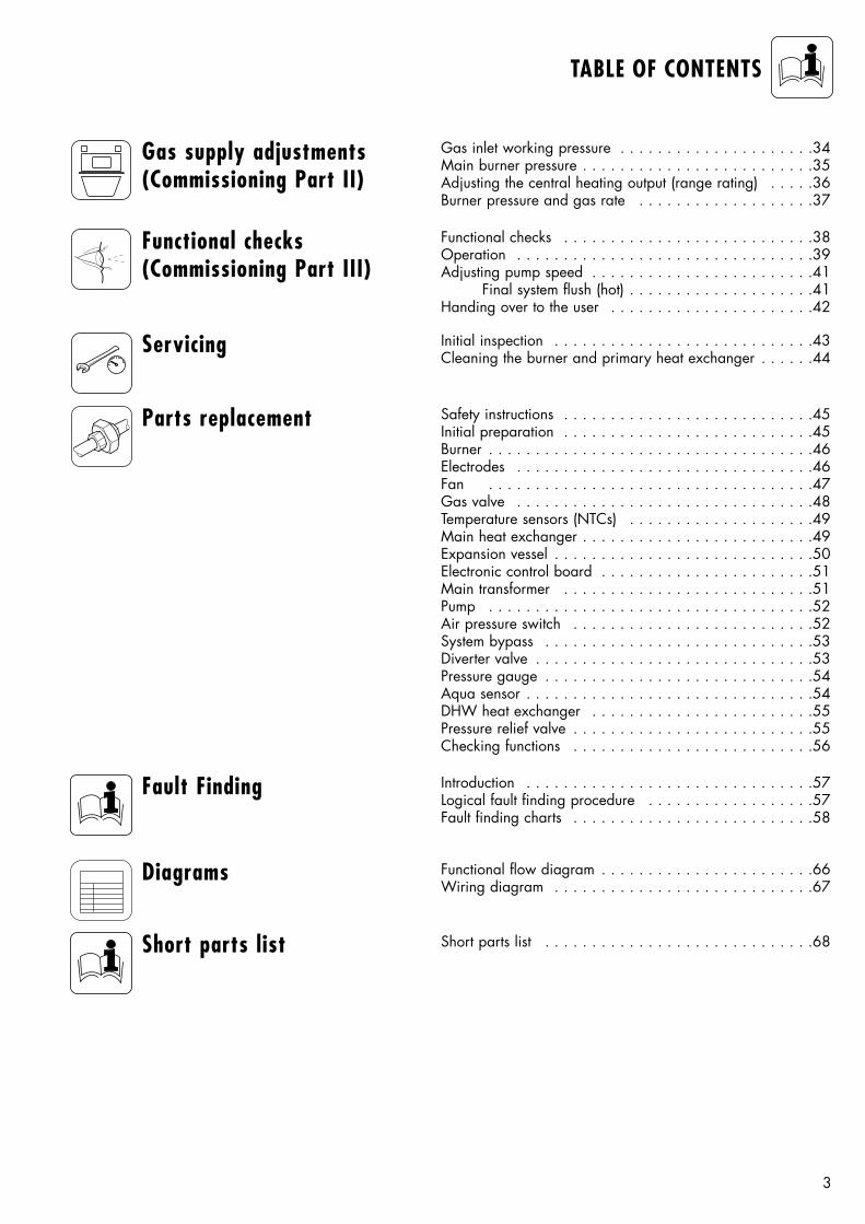
Gas supply adjustments(Commissioning Part II)
Servicing
Fault Finding Introduction . . . . . . . . . . . . . . . . . . . . . . . . . . . . . . .57Logical fault finding procedure . . . . . . . . . . . . . . . . . .57Fault finding charts . . . . . . . . . . . . . . . . . . . . . . . . . .58
Diagrams Functional flow diagram . . . . . . . . . . . . . . . . . . . . . . .66Wiring diagram . . . . . . . . . . . . . . . . . . . . . . . . . . . .67
Short parts list Short parts list . . . . . . . . . . . . . . . . . . . . . . . . . . . . .68
Initial inspection . . . . . . . . . . . . . . . . . . . . . . . . . . . .43Cleaning the burner and primary heat exchanger . . . . . .44
Parts replacement Safety instructions . . . . . . . . . . . . . . . . . . . . . . . . . . .45Initial preparation . . . . . . . . . . . . . . . . . . . . . . . . . . .45Burner . . . . . . . . . . . . . . . . . . . . . . . . . . . . . . . . . . .46Electrodes . . . . . . . . . . . . . . . . . . . . . . . . . . . . . . . .46Fan . . . . . . . . . . . . . . . . . . . . . . . . . . . . . . . . . . .47Gas valve . . . . . . . . . . . . . . . . . . . . . . . . . . . . . . . .48Temperature sensors (NTCs) . . . . . . . . . . . . . . . . . . . .49Main heat exchanger . . . . . . . . . . . . . . . . . . . . . . . . .49Expansion vessel . . . . . . . . . . . . . . . . . . . . . . . . . . . .50Electronic control board . . . . . . . . . . . . . . . . . . . . . . .51Main transformer . . . . . . . . . . . . . . . . . . . . . . . . . . .51Pump . . . . . . . . . . . . . . . . . . . . . . . . . . . . . . . . . . .52Air pressure switch . . . . . . . . . . . . . . . . . . . . . . . . . .52System bypass . . . . . . . . . . . . . . . . . . . . . . . . . . . . .53Diverter valve . . . . . . . . . . . . . . . . . . . . . . . . . . . . . .53Pressure gauge . . . . . . . . . . . . . . . . . . . . . . . . . . . . .54Aqua sensor . . . . . . . . . . . . . . . . . . . . . . . . . . . . . . .54DHW heat exchanger . . . . . . . . . . . . . . . . . . . . . . . .55Pressure relief valve . . . . . . . . . . . . . . . . . . . . . . . . . .55Checking functions . . . . . . . . . . . . . . . . . . . . . . . . . .56
Functional checks(Commissioning Part III)
Functional checks . . . . . . . . . . . . . . . . . . . . . . . . . . .38Operation . . . . . . . . . . . . . . . . . . . . . . . . . . . . . . . .39Adjusting pump speed . . . . . . . . . . . . . . . . . . . . . . . .41
Final system flush (hot) . . . . . . . . . . . . . . . . . . . .41Handing over to the user . . . . . . . . . . . . . . . . . . . . . .42
Gas inlet working pressure . . . . . . . . . . . . . . . . . . . . .34Main burner pressure . . . . . . . . . . . . . . . . . . . . . . . . .35Adjusting the central heating output (range rating) . . . . .36Burner pressure and gas rate . . . . . . . . . . . . . . . . . . .37
4
LIST OF CONTENTS
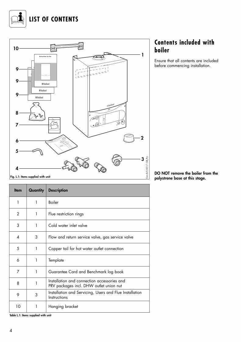
Contents included withboilerEnsure that all contents are includedbefore commencing installation.
DO NOT remove the boiler from thepolystrene base at this stage.
BEDIENUNGSANLEITUNG
BEDIENUNGSANLEITUNG
BEDIENUNGSANLEITUNG
BEDIENUNGSANLEITUNG
8
9
9
9
BEDIENUNGSANLEITUNG
Instructions for Use
7
10
6
1
2
5
4
I
0
3
Fig. L.1: Items supplied with unit
Table L.1: Items supplied with unit
Euro
B/S
021
/1 G
B_Pr
o
Item Quantity Description
1 1 Boiler
2 1 Flue restriction rings
3 1 Cold water inlet valve
5 1 Copper tail for hot water outlet connection
6 1 Template
4 3 Flow and return service valve, gas service valve
7 1 Guarantee Card and Benchmark log book
8 1 Installation and connection accessories and PRV packages incl. DHW outlet union nut
9 3 Installation and Servicing, Users and Flue InstallationInstructions
10 1 Hanging bracket
5
INTRODUCTION
The TURBOmax Pro is a fully automatic, wall mounted, room sealedcombination boiler for central heatingand domestic hot water. Domestic hotwater is supplied directly from theboiler, without requiring a coppercylinder, cold water tank, feed andexpansion tank and associated pipework. Domestic hot water has priority over central heating.
The boiler has been designed for usewith a sealed central heating system,and comes fully tested and assembledwith a built in circulating pump,expansion vessel and diverter valve.
The TURBOmax Pro has an output fordomestic hot water of 28 kW. Theboiler is easily sited on any internalwall and can be installed with eithera horizontal or vertical RSF (roomsealed fan assisted) flue. Two types offlue system are available, rear flueoutlet, top outlet (with turret) concentric flue system (100 mm outside diameter) and an extendedconcentric flue system (125 mm outside diameter). Flue extensions andadditional bends and elbows areavailable for both flue systems toincrease the siting flexibility. The boiler is not suitable for externalinstallation.
This boiler is available in NaturalGas. An optional LPG conversion kitis available.
If desired, an inhibitor may be usedin the system. Guidance on the use ofinhibitors is contained in these instructions.
The boiler contains a domestic hotwater heat exchanger. The temperature in the heat exchanger islimited by the boiler control systemand it is not necessary to install a
scale reducer on the cold mains to theboiler.However, in exceptionally hard waterareas to prevent scale formation inthe property hot water system pipework, a scale reducer may befitted.
TURBOmax Pro combination boilershave a built in diagnostic systemwhich indicates the operational statusof the boiler. This feature provides key information to aid commissioning andfault finding.
The data badge is fitted on the rearof the control panel.
See text of General Requirements forinstallation requirements or notes.
Vaillant ltd. support the Benchmarkinitiative. Within the informationpack, you will find a Benchmark LogBook. It is very important that this iscompleted correctly at the time ofinstallation, commisioning and hando-ver to the user.
Note: This boiler must be installedand service by a competent personin accordance with the Gas Safety(Installation and Use) Regulations1998. In the UK „CORGI“ registered installers undertake thework to a safe and satisfactory standard.
General Information
EC designation
TURBOmax Pro boilers (VUW GB282/2-3) carry the „CE“ Mark. Thisdemonstrates that the boilers fulfil theessential requirements of the GasAppliance Directive (90/396/EEC)and the Gas Appliance (Safety)Regulations 1992.
The „CE“ Mark also demonstrates thatthe boilers comply with the requirements of the ElectromagneticCompatibility Directive(89/336/EEC), the Low VoltageDirective (72/23/EEC), the BoilerEfficiency Directive (92/42/EEC) andthe Boiler (Efficiency) Regulations1993.
6
BOILER SPECIFICATION
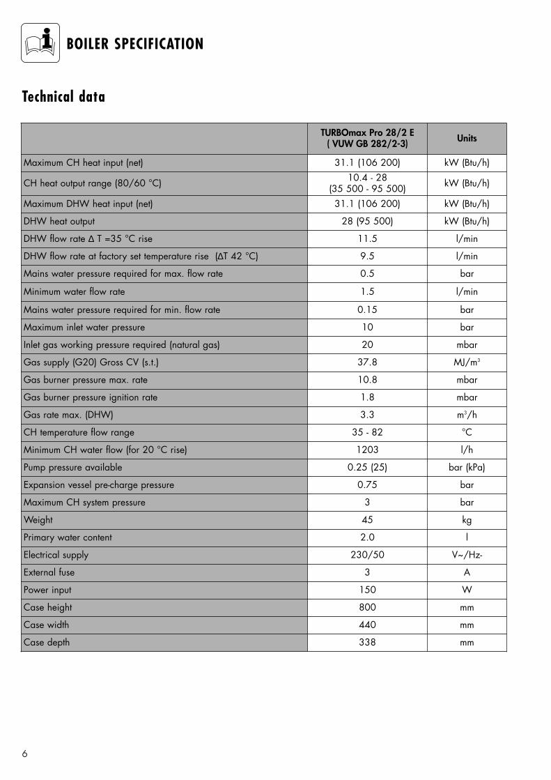
Technical data
TURBOmax Pro 28/2 E( VUW GB 282/2-3) Units
CH heat output range (80/60 °C) 10.4 - 28 (35 500 - 95 500) kW (Btu/h)
DHW heat output 28 (95 500) kW (Btu/h)
DHW flow rate ∆ T =35 °C rise 11.5 l/min
DHW flow rate at factory set temperature rise (∆T 42 °C) 9.5 l/min
Mains water pressure required for max. flow rate 0.5 bar
Minimum water flow rate 1.5 l/min
Mains water pressure required for min. flow rate 0.15 bar
Maximum inlet water pressure 10 bar
Inlet gas working pressure required (natural gas) 20 mbar
Gas burner pressure ignition rate 1.8 mbar
Gas rate max. (DHW) 3.3 m3/h
Weight 45 kg
Primary water content 2.0 l
Maximum CH heat input (net) 31.1 (106 200) kW (Btu/h)
Gas supply (G20) Gross CV (s.t.) 37.8 MJ/m3
Gas burner pressure max. rate 10.8 mbar
CH temperature flow range 35 - 82 °C
Minimum CH water flow (for 20 °C rise) 1203 l/h
Pump pressure available 0.25 (25) bar (kPa)
Expansion vessel pre-charge pressure 0.75 bar
Maximum CH system pressure 3 bar
Electrical supply 230/50 V~/Hz-
External fuse 3 A
Power input 150 W
Maximum DHW heat input (net) 31.1 (106 200) kW (Btu/h)
Case height 800 mm
Case width 440 mm
Case depth 338 mm
7
BOILER SPECIFICATION
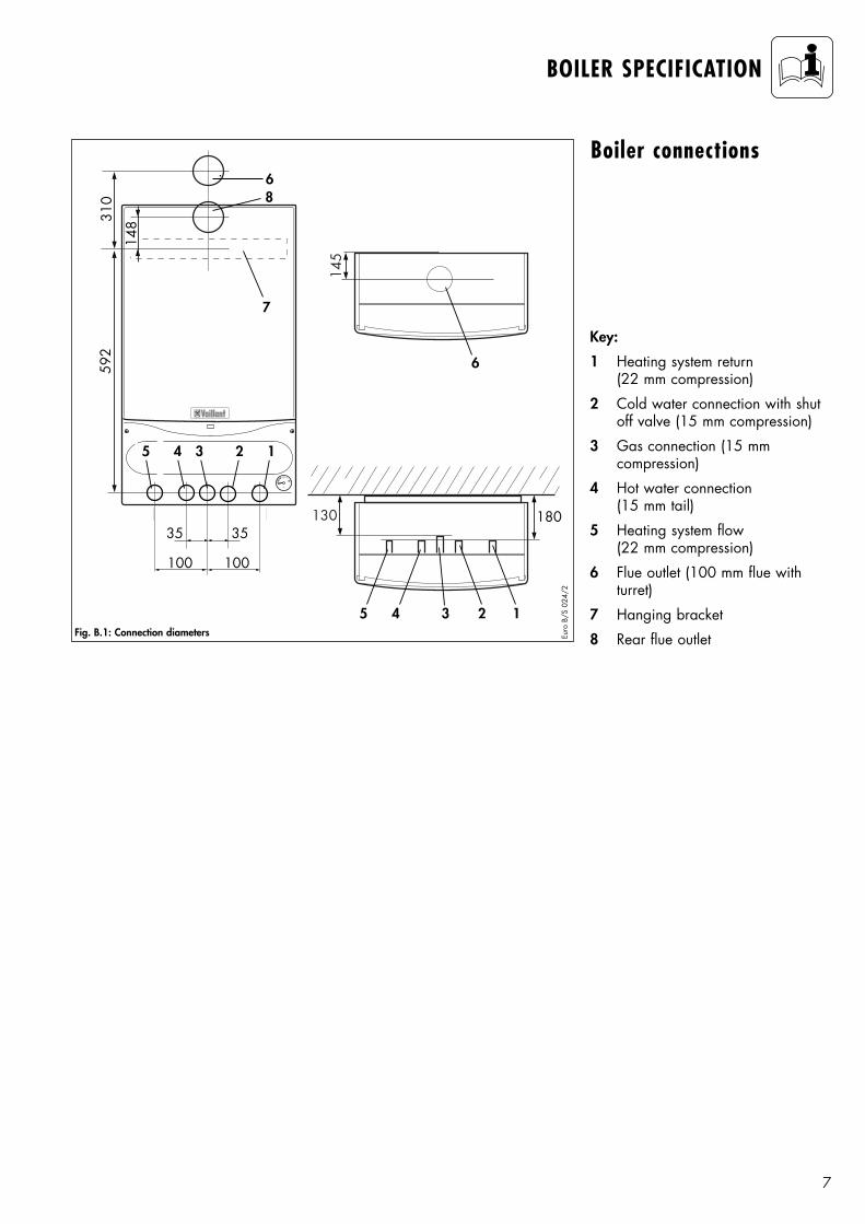
Boiler connections
0
7
6
310
592
145
6
5
100100
35 35
4 3 2
130 180
1
148
8
5 4 3 2 1
Fig. B.1: Connection diameters Euro
B/S
024
/2
Key:
1 Heating system return (22 mm compression)
2 Cold water connection with shutoff valve (15 mm compression)
3 Gas connection (15 mm compression)
4 Hot water connection (15 mm tail)
5 Heating system flow (22 mm compression)
6 Flue outlet (100 mm flue with turret)
7 Hanging bracket
8 Rear flue outlet
8
BOILER SPECIFICATION
C
C
1
2
3
4
5
6
7
8
9
10
11
12
1314
15
1716
18
19
2122
2324
2526
27
28
29
30
31
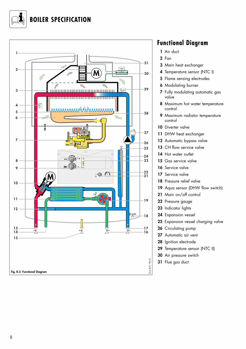
Functional Diagram1 Air duct2 Fan3 Main heat exchanger4 Temperature sensor (NTC I)5 Flame sensing electrodes6 Modulating burner7 Fully modulating automatic gas
value8 Maximum hot water temperature
control9 Maximum radiator temperature
control10 Diverter valve11 DHW heat exchanger12 Automatic bypass valve13 CH flow service valve14 Hot water outlet15 Gas service valve16 Service valve17 Service valve18 Pressure relief valve19 Aqua sensor (DHW flow switch)21 Main on/off control22 Pressure gauge23 Indicator lights24 Expansion vessel25 Expansion vessel charging valve26 Circulating pump27 Automatic air vent28 Ignition electrode29 Temperature sensor (NTC II)30 Air pressure switch31 Flue gas duct
Fig. B.2: Functional Diagram Euro
B/S
196
/0
9
GENERAL REQUIREMENTS
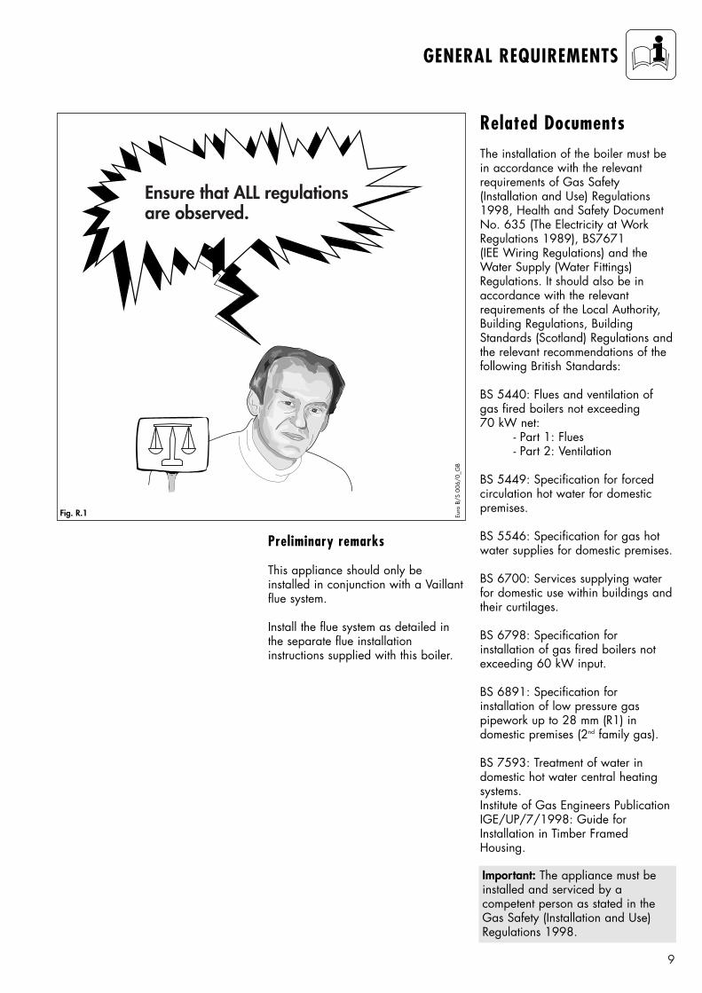
Ensure that ALL regulationsare observed.
Fig. R.1 Euro
B/S
006
/0_G
B
Related DocumentsThe installation of the boiler must bein accordance with the relevant requirements of Gas Safety(Installation and Use) Regulations1998, Health and Safety DocumentNo. 635 (The Electricity at WorkRegulations 1989), BS7671 (IEE Wiring Regulations) and theWater Supply (Water Fittings)Regulations. It should also be inaccordance with the relevant requirements of the Local Authority,Building Regulations, BuildingStandards (Scotland) Regulations andthe relevant recommendations of thefollowing British Standards:
BS 5440: Flues and ventilation ofgas fired boilers not exceeding 70 kW net:
- Part 1: Flues- Part 2: Ventilation
BS 5449: Specification for forced circulation hot water for domestic premises.
BS 5546: Specification for gas hotwater supplies for domestic premises.
BS 6700: Services supplying waterfor domestic use within buildings andtheir curtilages.
BS 6798: Specification for installation of gas fired boilers notexceeding 60 kW input.
BS 6891: Specification for installation of low pressure gas pipework up to 28 mm (R1) in domestic premises (2nd family gas).
BS 7593: Treatment of water indomestic hot water central heatingsystems.Institute of Gas Engineers PublicationIGE/UP/7/1998: Guide forInstallation in Timber FramedHousing.
Important: The appliance must beinstalled and serviced by a competent person as stated in theGas Safety (Installation and Use)Regulations 1998.
Preliminary remarks
This appliance should only be installed in conjunction with a Vaillantflue system.
Install the flue system as detailed inthe separate flue installation instructions supplied with this boiler.
10
GENERAL REQUIREMENTS
Gas SupplyThe gas supplier should ensure theavailability of an adequate supply ofgas.
A gas meter may only be connectedto the service pipe by the supplier ofgas or their contractor.
An existing meter should be checkedto ensure that it is capable of passingthe rate of gas supply required.
Installation pipes should be fitted inaccordance with BS 6891.
Pipework from the meter to the boilermust be of an adequate size. Do notuse pipes of a smaller size than theboiler gas connection (15 mm).
The complete installation must betested for soundness and purged asdescribed in BS 6891.
Boiler locationThe location chosen for the boilermust permit the provision of a satisfactory flue termination. The location must also provide adequatespace for servicing and air circulationaround the boiler. The boiler may beinstalled in any room, although particular attention is drawn to therequirements of BS7671 (IEERegulations) and, in Scotland, theelectrical provisions of the BuildingStandards (Scotland) Regulations, inrespect of the installation of a boilerin a room containing a bath or shower.
Where the installation of the boilerwill be in an unusual location, specialprocedures may be necessary and BS5546 and BS 6798 give detailed guidance on this aspect. The boilermust be mounted on a flat, verticalwall, which must be sufficiently robustto take the weight of the boiler. Theboiler may be installed on a combustible wall, subject to the requirements of the Local Authoritiesand Building Regulations.A compartment used to enclose theboiler must be designed and constructed specifically for this purpose. (An existing cupboard orcompartment may be used providedthat it is modified for the purpose).Details of essential features of cupboard/compartment design including airing cupboard installations are given in BS 6798.If the boiler is to be fitted in a timberframed building, it should be fitted inaccordance with Institute of GasEngineers PublicationIGE/UP/7/1998 „Guide for GasInstallation in Timber FramedHousing“.
Note: Where a room sealed boileris installed in a room containing abath or shower, any electrical switchor boiler control utilising mains electricity should be so situated thatit cannot be touched by a personusing the bath or shower.
11
GENERAL REQUIREMENTS
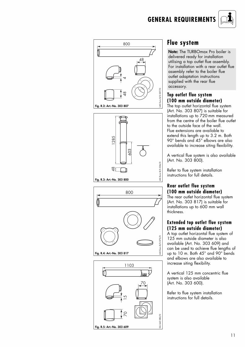
Top outlet flue system(100 mm outside diameter)The top outlet horizontal flue system(Art. No. 303 807) is suitable forinstallations up to 720 mm measuredfrom the centre of the boiler flue outletto the outside face of the wall. Flue extensions are available toextend this length up to 3.2 m. Both90° bends and 45° elbows are alsoavailable to increase siting flexibility.
A vertical flue system is also available(Art. No. 303 800).
Refer to flue system installation instructions for full details.
Rear outlet flue system(100 mm outside diameter)The rear outlet horizontal flue system(Art. No. 303 817) is suitable for installations up to 600 mm wallthickness.
Extended top outlet flue system (125 mm outside diameter)A top outlet horizontal flue system of125 mm outside diameter is also available (Art. No. 303 609) andcan be used to achieve flue lengths ofup to 10 m. Both 45° and 90° bendsand elbows are also available toincrease siting flexibility.
A vertical 125 mm concentric fluesystem is also available (Art. No. 303 600).
Refer to flue system installation instructions for full details.
Flue systemNote: The TURBOmax Pro boiler isdelivered ready for installation utilising a top outlet flue assembly.For installation with a rear outlet flueassembly refer to the boiler flue outlet adaptation instructions supplied with the rear flue accessory.
48
800
48
4
Fig. R.2: Art.-No. 303 807 LAS
Euro
B/S
037
/0
4812
85
603
Fig. R.3: Art.-No. 303 800 LAS
Euro
B/S
036
/0
800
Fig. R.4: Art.-No. 303 817 LAS
Euro
B/S
073
/0
Fig. R.5: Art.-No. 303 609 GU
LA
Z 08
2/070
1103
70
15
12
GENERAL REQUIREMENTS
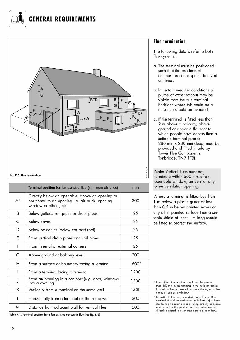
Flue termination
The following details refer to bothflue systems.
a. The terminal must be positionedsuch that the products of combustion can disperse freely atall times.
b. In certain weather conditions aplume of water vapour may bevisible from the flue terminal.Positions where this could be a nuisance should be avoided.
c. If the terminal is fitted less than 2 m above a balcony, above ground or above a flat roof towhich people have access then asuitable terminal guard; 280 mm x 280 mm deep, must beprovided and fitted (made byTower Flue Components,Tonbridge, TN9 1TB).
Note: Vertical flues must not terminate within 600 mm of an openable window, air vent or anyother ventilation opening.
Where a terminal is fitted less than 1 m below a plastic gutter or lessthan 0.5 m below painted eaves orany other painted surface then a sui-table shield at least 1 m long shouldbe fitted to protect the surface.
A
BCD
A
G
H, IF J
B F M
L
LK
K
G
G
F F
E
AA
Fig. R.6: Flue termination
Terminal position for fan-assisted flue (minimum distance) mm
A1) 300
B Below gutters, soil pipes or drain pipes 25
C Below eaves 25
D Below balconies (below car port roof) 25
E From vertical drain pipes and soil pipes 25
F From internal or external corners 25
G Above ground or balcony level 300
I From a terminal facing a terminal 1200
K Vertically from a terminal on the same wall 1500
L Horizontally from a terminal on the same wall 300
M Distance from adjacent wall for vertical Flue 500
GW
595
/2
J From an opening in a car port (e.g. door, window)into a dweling 1200
H From a surface or boundary facing a terminal 600*
Directly below an openable, above an opening orhorizontal to an opening i.e. air brick, openingwindow or other , etc
Table R.1. Terminal position for a fan assisted concentric flue (see fig. R.6)
1) In addition, the terminal should not be nearer than 150 mm to an opening in the building fabricformed for the purpose of accommodating a built-inelement such as a window.
* BS 5440-1 It is recommended that a fanned flue terminal should be positioned as follows: a) at least2m from an opening in a building directly opposite,and b) so that the products of combustion are notdirectly directed to discharge across a boundary.
13
GENERAL REQUIREMENTS
Cupboard or compartmentventilationTURBOmax Pro combination boilersare very high efficiency appliances.As a consequence the heat loss fromthe appliance casing during operation is very low. For cupboardor compartment installations it is therefore not necessary to provideany high or low level permanent airvents for cooling purposes.
Air supplyDetailed recommendations for air supply are given in BS 5440: Part 2.
It is not necessary to have an air ventin the room or internal space in whichthe boiler is installed.
Electrical supplyA 230 V, ~ 50 Hz single phase electricity supply fused to 3 Amp.must be provided in accordance withthe latest edition of BS7671 (IEEWiring Regulations) and any otherlocal regulations that may apply.
The method of connection to themains electricity supply must providea means of completely isolating theboiler and its ancillary controls.Isolation is preferably by the use of afused three pin plug and unswitchedshuttered socket outlet, both complying with the requirements of BS 1363. Alternatively, a 3 Amp.fused doublepole switch with a 3 mmcontact separation on both poles maybe used.This appliance must be earthed.
14
GENERAL REQUIREMENTS
Guide to system requirements
Water circulation system
Detailed recommendations for thewater circulation system are given inBS 6798 and BS 5449: Part 1 (forsmall bore and micro bore centralheating systems).
Pipework not forming part of the useful heating surface should be insulated to help prevent heat lossand possible freezing, particularlywhere pipes are run through roof spaces and ventilated underfloor spaces.
Draining taps must be located inaccessible positions which permit thedraining of the whole system including the boiler and the hot watersystem. Draining taps should be atleast 1/2 in. BSP nominal size andbe in accordance with BS 2879.
The boiler is suitable for use withminibore or microbore systems.Copper tubing to BS 2871: Part 1should be used for water carryingpipework. All capillary joints in theDHW pipework must be made withlead free solder.
Particularly where a new boiler is tobe fitted to an existing system, it isgood practice that the system isthoroughly cleansed. This cleansingshould take place prior to the fittingof the new boiler and be in accordance with BS 7593.
For advice on the application ofsystem cleansers contact eitherSentinel, Betz Dearborn Ltd. Widnes,Cheshire, WA8 8UD. Tel: 0151 495 1861or FernoxAlpha-Fry TechnologiesTandem HouseMarlow Way, Beddington Farm RoadCroydon CRO 4xSTel. 0870 601 5000Fernox technicalhelp line 01799 550811
Filling and make up
The system should be filled with watervia a seperate filling point at a convienient position on the heatingcicuit. The connection must be removed when filling is completed.Where local Water Authority regulation does not allow temporaryconnection, a sealed system fillerpump with break tank must be used.The heating system will not be filledautomatically from the domestic hotwater side.
(Alternative methods of filling sealedsystems are given in BS 5449).
Pressure relief valve
A pressure relief valve is provided with the boiler. This safety device isrequired on all sealed C.H. systemsand is preset at 3 bar and providedwith a 15 mm compression connec-tion for a discharge pipe, which mustbe of no less than 15 mm in diame-ter. The Pressure Relief Valve must notbe used for draining purposes.
Pressure gauge
This is factory fitted to the boiler andindicates the primary circuit pressureto facilitate filling and testing.
15
GENERAL REQUIREMENTS
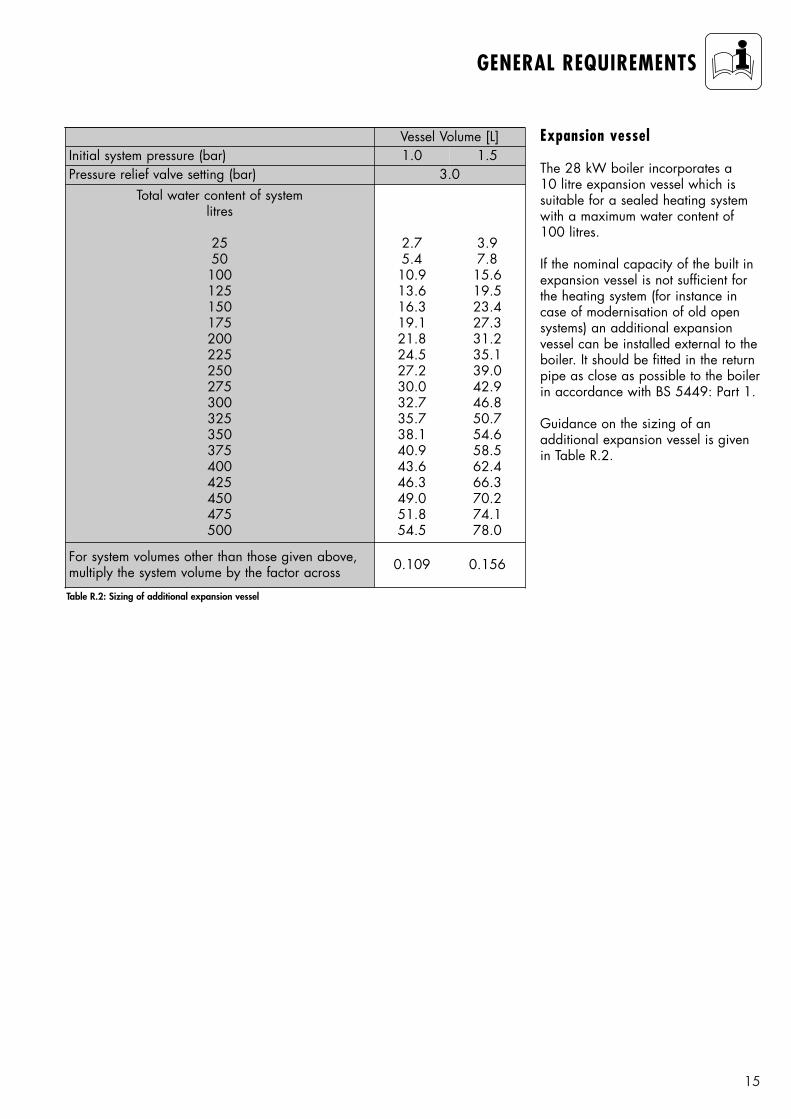
Expansion vessel
The 28 kW boiler incorporates a 10 litre expansion vessel which is suitable for a sealed heating systemwith a maximum water content of 100 litres.
If the nominal capacity of the built inexpansion vessel is not sufficient forthe heating system (for instance incase of modernisation of old opensystems) an additional expansion vessel can be installed external to theboiler. It should be fitted in the returnpipe as close as possible to the boilerin accordance with BS 5449: Part 1.
Guidance on the sizing of an additional expansion vessel is givenin Table R.2.
Table R.2: Sizing of additional expansion vessel
Vessel Volume [L]Initial system pressure (bar) 1.0 1.5Pressure relief valve setting (bar) 3.0
Total water content of systemlitres
2550
100125150175200225250275300325350375400425450475500
2.75.410.913.616.319.121.824.527.230.032.735.738.140.943.646.349.051.854.5
3.97.815.619.523.427.331.235.139.042.946.850.754.658.562.466.370.274.178.0
For system volumes other than those given above,multiply the system volume by the factor across 0.109 0.156
16
GENERAL REQUIREMENTS
0 100 200 300 400 500 600 700 800 900 1000 1100 1200 1300 1400
50
100
150
200
250
300
350
400
450
500
550
600
650
700
Volume flow [l/min]
Lift
[mba
r]
setting II
setting I
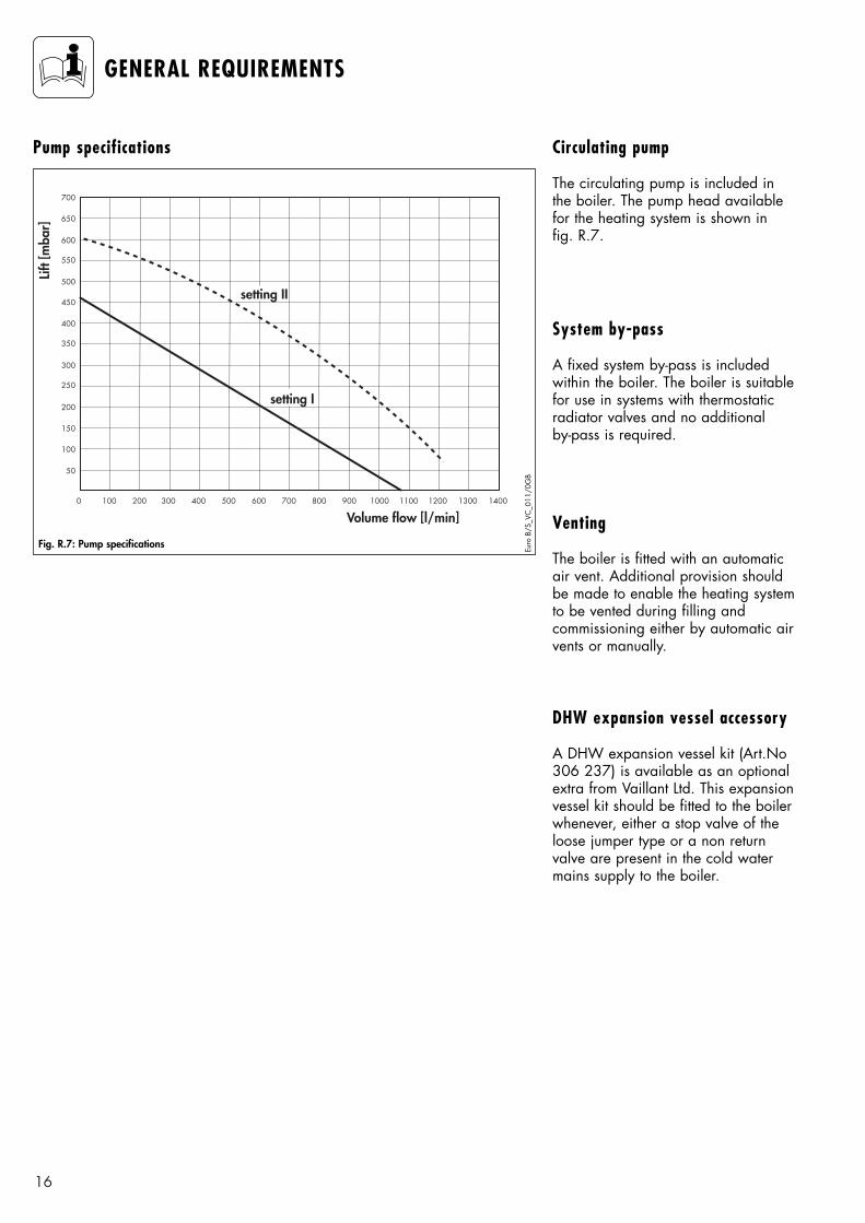
Fig. R.7: Pump specifications
Euro
B/S
_VC
_011
/0G
B
Pump specifications Circulating pump
The circulating pump is included inthe boiler. The pump head availablefor the heating system is shown in fig. R.7.
System by-pass
A fixed system by-pass is included within the boiler. The boiler is suitablefor use in systems with thermostaticradiator valves and no additional by-pass is required.
Venting
The boiler is fitted with an automaticair vent. Additional provision shouldbe made to enable the heating systemto be vented during filling and commissioning either by automatic airvents or manually.
DHW expansion vessel accessory
A DHW expansion vessel kit (Art.No306 237) is available as an optionalextra from Vaillant Ltd. This expansionvessel kit should be fitted to the boiler whenever, either a stop valve of theloose jumper type or a non returnvalve are present in the cold watermains supply to the boiler.
17
GENERAL REQUIREMENTS
150
5
200
5005
I
00 120
60
9030
°Cbar
4
3
21
0
Euro
B/S
022
/1
440
800
338
I
00 120
60
9030
°Cbar
4
3
2
1
0
Euro
B/S
023
/1
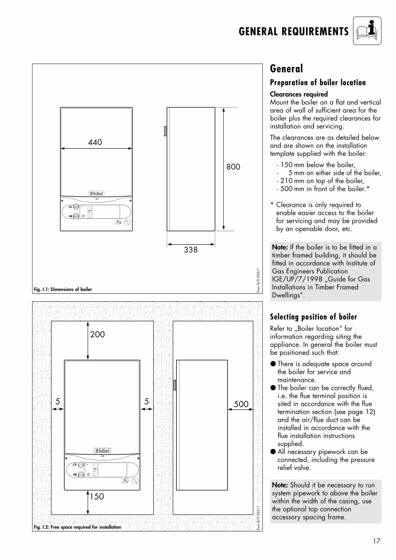
GeneralPreparation of boiler locationClearances requiredMount the boiler on a flat and verticalarea of wall of sufficient area for theboiler plus the required clearances forinstallation and servicing.
The clearances are as detailed belowand are shown on the installation template supplied with the boiler:
- 150 mm below the boiler,- 5 mm on either side of the boiler,- 210 mm on top of the boiler,- 500 mm in front of the boiler.*
* Clearance is only required to enable easier access to the boilerfor servicing and may be providedby an openable door, etc.
Selecting position of boilerRefer to „Boiler location“ for information regarding siting the appliance. In general the boiler mustbe positioned such that:
● There is adequate space aroundthe boiler for service and maintenance.
● The boiler can be correctly flued,i.e. the flue terminal position issited in accordance with the fluetermination section (see page 12)and the air/flue duct can be installed in accordance with theflue installation instructions supplied.
● All necessary pipework can beconnected, including the pressurerelief valve.
Note: If the boiler is to be fitted in atimber framed building, it should befitted in accordance with Institute ofGas Engineers PublicationIGE/UP/7/1998 „Guide for GasInstallations in Timber FramedDwellings“.
Fig. I.2: Free space required for installation
Fig. I.1: Dimensions of boiler
Note: Should it be necessary to runsystem pipework to above the boilerwithin the width of the casing, usethe optional top connection accessory spacing frame.
55
210
124163 03240/242/280/282/824/828 Pro/Plus
60/100
07/2
000
1241
63_0
3
1
3
2
18
BOILER INSTALLATION SEQUENCE
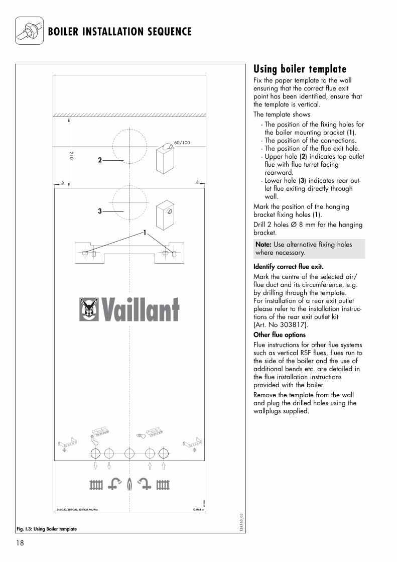
Using boiler templateFix the paper template to the wallensuring that the correct flue exitpoint has been identified, ensure thatthe template is vertical. The template shows
- The position of the fixing holes forthe boiler mounting bracket (1).
- The position of the connections.- The position of the flue exit hole.- Upper hole (2) indicates top outletflue with flue turret facing rearward.
- Lower hole (3) indicates rear out-let flue exiting directly throughwall.
Mark the position of the hangingbracket fixing holes (1).Drill 2 holes Ø 8 mm for the hangingbracket.
Identify correct flue exit.Mark the centre of the selected air/flue duct and its circumference, e.g.by drilling through the template. For installation of a rear exit outletplease refer to the installation instruc-tions of the rear exit outlet kit(Art. No 303817).Other flue optionsFlue instructions for other flue systemssuch as vertical RSF flues, flues run tothe side of the boiler and the use ofadditional bends etc. are detailed inthe flue installation instructions provided with the boiler.Remove the template from the walland plug the drilled holes using thewallplugs supplied.
Note: Use alternative fixing holeswhere necessary.
Fig. I.3: Using Boiler template
I
0
3
320
131
22
26,527
131
105 105
1
2
0
120
6090
30
°C
bar4
32
1
0
Euro
B/S
043
/1
19
BOILER INSTALLATION SEQUENCE
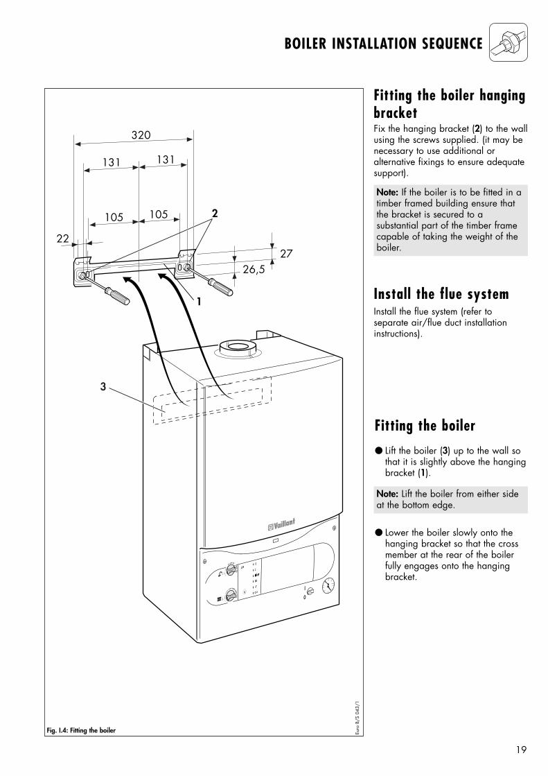
Fig. I.4: Fitting the boiler
Fitting the boiler● Lift the boiler (3) up to the wall so
that it is slightly above the hangingbracket (1).
● Lower the boiler slowly onto thehanging bracket so that the crossmember at the rear of the boilerfully engages onto the hangingbracket.
Note: Lift the boiler from either sideat the bottom edge.
Install the flue systemInstall the flue system (refer to separate air/flue duct installationinstructions).
Fitting the boiler hangingbracketFix the hanging bracket (2) to the wallusing the screws supplied. (it may benecessary to use additional or alternative fixings to ensure adequatesupport).
Note: If the boiler is to be fitted in atimber framed building ensure thatthe bracket is secured to a substantial part of the timber framecapable of taking the weight of theboiler.
3
I
0
2
I
0
90°90°
1
Euro
B/S
041
/1
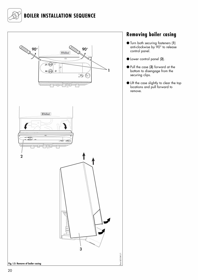
Fig. I.5: Remove of boiler casing
20
BOILER INSTALLATION SEQUENCE
Removing boiler casing● Turn both securing fasteners (1)
anti-clockwise by 90° to releasecontrol panel.
● Lower control panel (2).
● Pull the case (3) forward at the bottom to disengage from the securing clips.
● Lift the case slightly to clear the toplocations and pull forward to remove.
21
BOILER INSTALLATION SEQUENCE
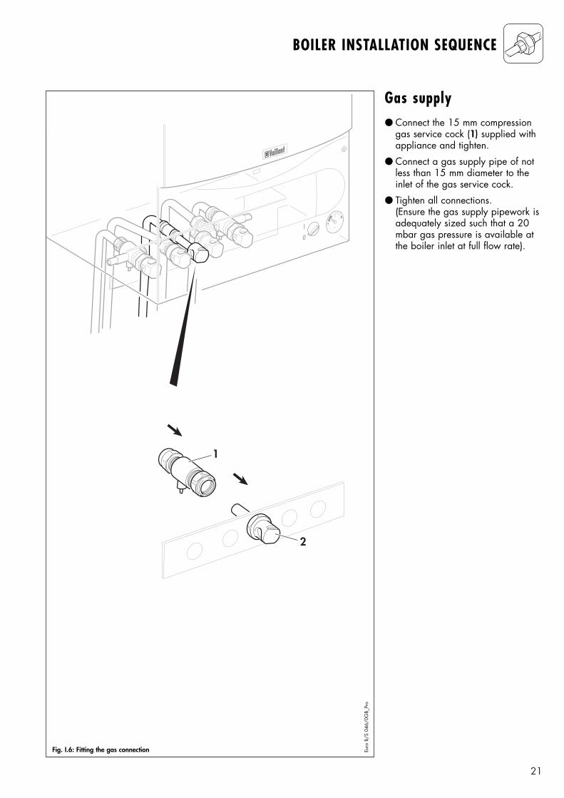
Gas supply● Connect the 15 mm compression
gas service cock (1) supplied withappliance and tighten.
● Connect a gas supply pipe of notless than 15 mm diameter to theinlet of the gas service cock.
● Tighten all connections.(Ensure the gas supply pipework isadequately sized such that a 20mbar gas pressure is available atthe boiler inlet at full flow rate).
I
0
1
2
Euro
B/S
046
/0G
B_Pr
o
Fig. I.6: Fitting the gas connection
22
BOILER INSTALLATION SEQUENCE
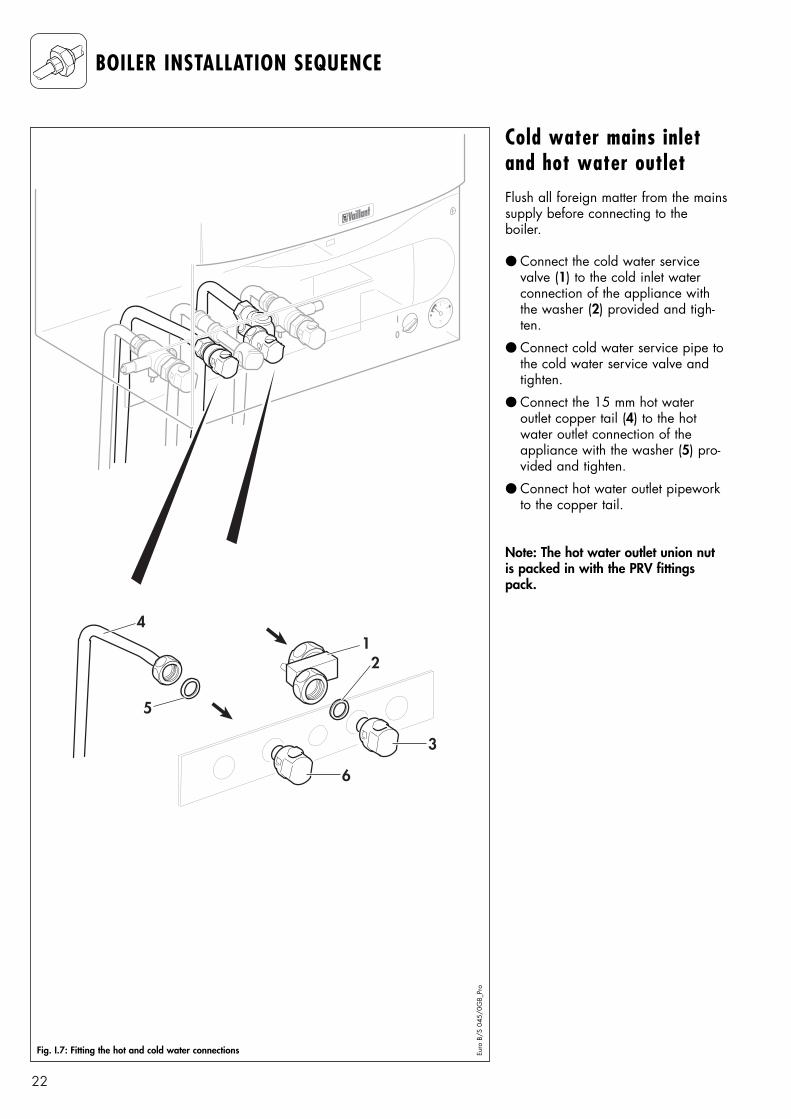
Cold water mains inletand hot water outletFlush all foreign matter from the mainssupply before connecting to the boiler.
● Connect the cold water servicevalve (1) to the cold inlet waterconnection of the appliance withthe washer (2) provided and tigh-ten.
● Connect cold water service pipe tothe cold water service valve andtighten.
● Connect the 15 mm hot water outlet copper tail (4) to the hotwater outlet connection of theappliance with the washer (5) pro-vided and tighten.
● Connect hot water outlet pipeworkto the copper tail.
Note: The hot water outlet union nutis packed in with the PRV fittingspack.
12
3
4
5
6
I
0
Euro
B/S
045
/0G
B_Pr
o
Fig. I.7: Fitting the hot and cold water connections
23
BOILER INSTALLATION SEQUENCE
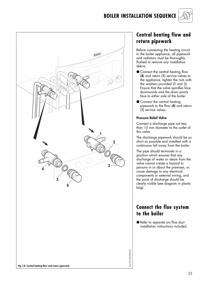
Central heating flow andreturn pipeworkBefore connecting the heating circuitto the boiler appliance, all pipeworkand radiators must be thoroughly flushed to remove any installationdebris.
● Connect the central heating flow(4) and return (1) service valves tothe appliance, tighten the nuts withthe washers provided (5 and 2).Ensure that the valve spindles facedownwards and the drain pointsface to either side of the boiler.
● Connect the central heating pipework to the flow (4) and return(1) service valves.
Pressure Relief Valve
Connect a discharge pipe not lessthan 15 mm diameter to the outlet ofthis valve.
The discharge pipework should be asshort as possible and installed with acontinuous fall away from the boiler.
The pipe should terminate in a position which ensures that anydischarge of water or steam from thevalve cannot create a hazard to persons in or about the premises, orcause damage to any electrical components or external wiring, andthe point of discharge should beclearly visible (see diagram in plasticbag).
Connect the flue systemto the boiler● Refer to separate air/flue duct
installation instructions included.
I
0
1
2
3
65
4
Fig. I.8: Central heating flow and return pipework Euro
B/S
044
/0G
B_Pr
o
24
BOILER INSTALLATION SEQUENCE
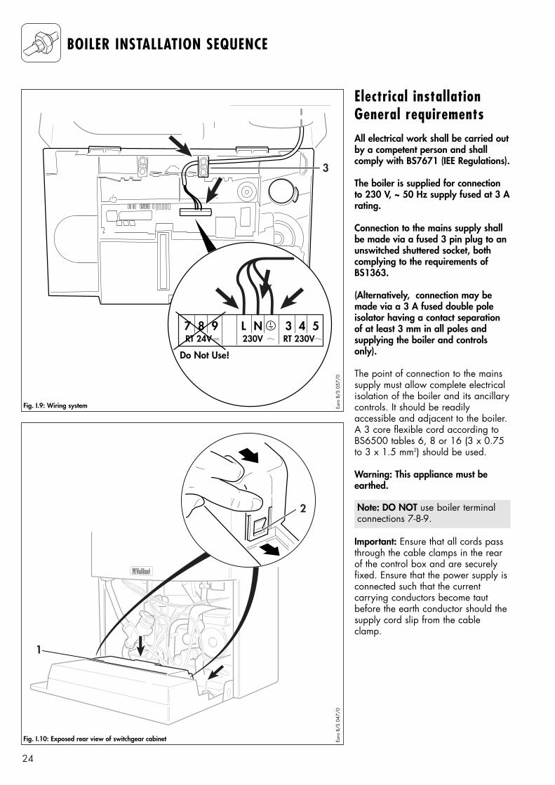
Electrical installationGeneral requirementsAll electrical work shall be carried outby a competent person and shall comply with BS7671 (IEE Regulations).
The boiler is supplied for connectionto 230 V, ~ 50 Hz supply fused at 3 Arating.
Connection to the mains supply shallbe made via a fused 3 pin plug to anunswitched shuttered socket, bothcomplying to the requirements ofBS1363.
(Alternatively, connection may bemade via a 3 A fused double poleisolator having a contact separationof at least 3 mm in all poles and supplying the boiler and controlsonly).
The point of connection to the mainssupply must allow complete electricalisolation of the boiler and its ancillarycontrols. It should be readily accessible and adjacent to the boiler.A 3 core flexible cord according toBS6500 tables 6, 8 or 16 (3 x 0.75to 3 x 1.5 mm2) should be used.
Warning: This appliance must beearthed.
Important: Ensure that all cords passthrough the cable clamps in the rearof the control box and are securelyfixed. Ensure that the power supply isconnected such that the current carrying conductors become tautbefore the earth conductor should thesupply cord slip from the cableclamp.
Note: DO NOT use boiler terminalconnections 7-8-9.
3
NL987 543RT 24V 230V RT 230V
Fig. I.9: Wiring system Euro
B/S
057
/0
2
1
Fig. I.10: Exposed rear view of switchgear cabinet Euro
B/S
047
/0
Do Not Use!
25
BOILER INSTALLATION SEQUENCE
CautionMains connection terminals Land N remain live even whenthe boiler on/off control isswitched off. ● Refit the terminal box cover by
pushing into place until it clipsback into position.
● Raise the control panel and securein place.
Connection to the mainsupply● Lower the control panel.
● Unclip the terminal box cover (1)from the control panel (2).
● Feed the power supply cord in tothe appliance as shown (fig I.9).
● Use cable clamps.
● Connect the power supply cord asfollows (Fig. I.11, on page 26).
Green/yellow (earth) wire boiler terminal Earth sign
Blue (neutral) wireboiler terminal N
Brown (live) wireboiler terminal L
Note: DO NOT use boiler terminalconnections 7-8-9.
26
BOILER INSTALLATION SEQUENCE
Euro
B/S
048
/1
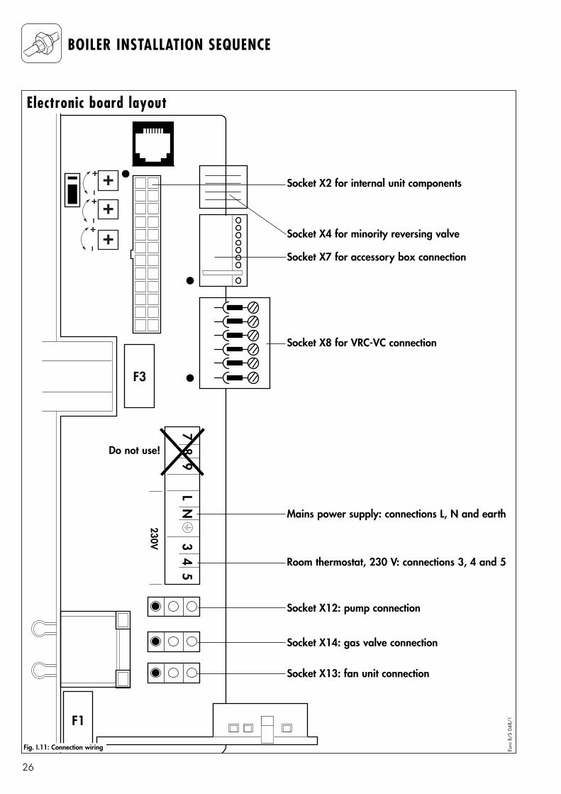
Socket X2 for internal unit components
Socket X4 for minority reversing valve
Socket X7 for accessory box connection
Socket X8 for VRC-VC connection
Room thermostat, 230 V: connections 3, 4 and 5
Socket X12: pump connection
Socket X14: gas valve connection
Socket X13: fan unit connection
Mains power supply: connections L, N and earth
Do not use!
Electronic board layout
Fig. I.11: Connection wiring
27
BOILER INSTALLATION SEQUENCE
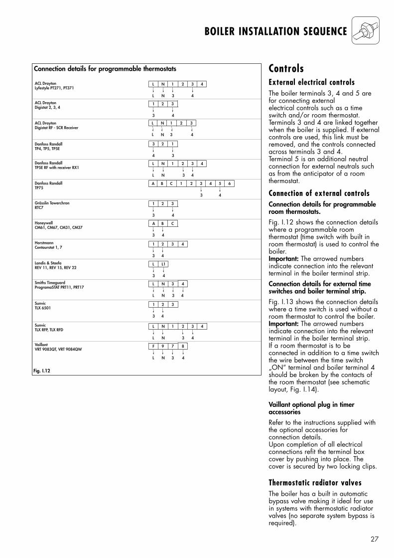
ControlsExternal electrical controlsThe boiler terminals 3, 4 and 5 arefor connecting external electrical controls such as a timeswitch and/or room thermostat.Terminals 3 and 4 are linked togetherwhen the boiler is supplied. If externalcontrols are used, this link must beremoved, and the controls connectedacross terminals 3 and 4.Terminal 5 is an additional neutralconnection for external neutrals suchas from the anticipator of a room thermostat.
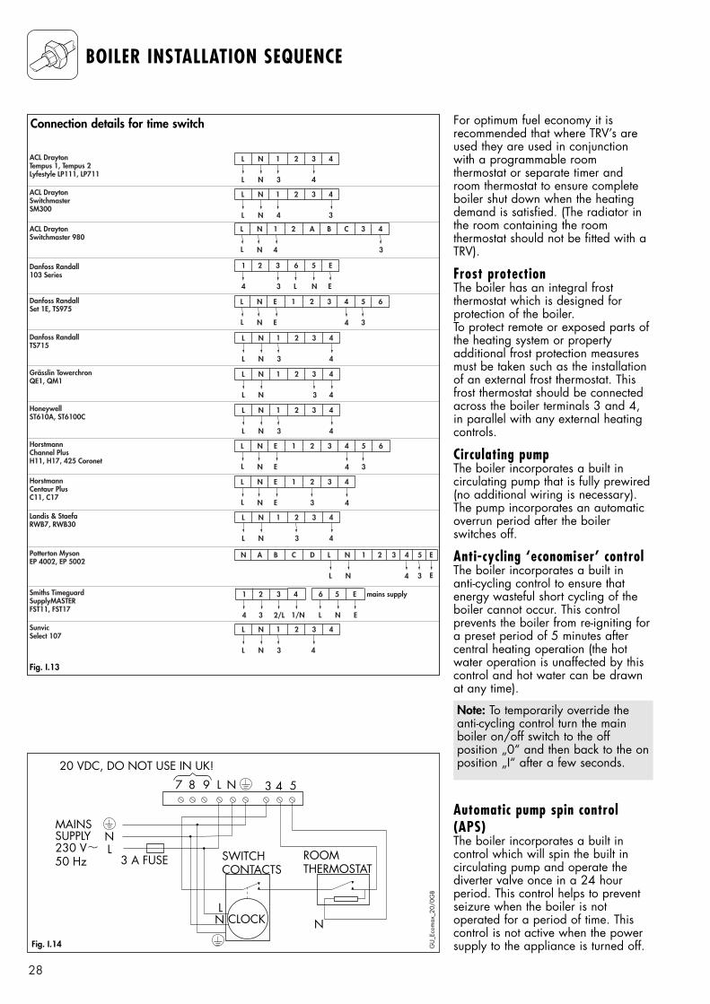
Connection of external controlsConnection details for programmableroom thermostats.Fig. I.12 shows the connection detailswhere a programmable room thermostat (time switch with built inroom thermostat) is used to control theboiler.Important: The arrowed numbers indicate connection into the relevantterminal in the boiler terminal strip.Connection details for external timeswitches and boiler terminal strip.Fig. I.13 shows the connection detailswhere a time switch is used without aroom thermostat to control the boiler.Important: The arrowed numbers indicate connection into the relevantterminal in the boiler terminal strip.If a room thermostat is to be connected in addition to a time switchthe wire between the time switch„ON“ terminal and boiler terminal 4should be broken by the contacts ofthe room thermostat (see schematiclayout, Fig. I.14).
Vaillant optional plug in timer accessoriesRefer to the instructions supplied withthe optional accessories for connection details.Upon completion of all electricalconnections refit the terminal boxcover by pushing into place. Thecover is secured by two locking clips.
Thermostatic radiator valvesThe boiler has a built in automaticbypass valve making it ideal for usein systems with thermostatic radiatorvalves (no separate system bypass isrequired).
Connection details for programmable thermostats
Fig. I.12
L N 2 3 4
L N 3 4
1ACL DraytonLyfestyle PT271, PT371
ACL DraytonDigistat 2, 3, 4
ACL DraytonDigistat RF - SCR Receiver
Danfoss RandallTP4, TP5, TP5E
Danfoss RandallTP5E RF with receiver RX1
Danfoss RandallTP75
Grässlin TowerchronRTC7
HoneywellCM61, CM67, CM31, CM37
HorstmannCentaurstat 1, 7
Landis & StaefaREV 11, REV 15, REV 22
1 2
3 4
3
SunvicTLX 6501
SunvicTLX RFP, TLX RFD
VaillantVRT 9083QT, VRT 9084QW
N 1 3
N 3
2L
L 4
3 2
4 3
1
L N 2 3 4
L N 3 4
1
B C 2 3 41A
3
5 6
4
1 2
3 4
3
A B
3 4
C
1 2 4
3 4
3
L L1
3 4
Smiths TimeguardProgramaSTAT PRT11, PRT17
L N 4
L N
3
3 4
1 2
3 4
3
L N 2 3 4
L N 3 4
1
F 9 8
L N
7
3 4
28
BOILER INSTALLATION SEQUENCE
For optimum fuel economy it is recommended that where TRV’s areused they are used in conjunctionwith a programmable room thermostat or separate timer androom thermostat to ensure completeboiler shut down when the heatingdemand is satisfied. (The radiator inthe room containing the room thermostat should not be fitted with aTRV).
Frost protectionThe boiler has an integral frost thermostat which is designed for protection of the boiler.To protect remote or exposed parts ofthe heating system or property additional frost protection measuresmust be taken such as the installationof an external frost thermostat. Thisfrost thermostat should be connectedacross the boiler terminals 3 and 4,in parallel with any external heatingcontrols.
Circulating pumpThe boiler incorporates a built in circulating pump that is fully prewired(no additional wiring is necessary).The pump incorporates an automaticoverrun period after the boiler switches off.
Anti-cycling ‘economiser’ controlThe boiler incorporates a built in anti-cycling control to ensure thatenergy wasteful short cycling of theboiler cannot occur. This control prevents the boiler from re-igniting fora preset period of 5 minutes after central heating operation (the hotwater operation is unaffected by thiscontrol and hot water can be drawnat any time).
Automatic pump spin control(APS)The boiler incorporates a built in control which will spin the built in circulating pump and operate thediverter valve once in a 24 hour period. This control helps to preventseizure when the boiler is not operated for a period of time. Thiscontrol is not active when the powersupply to the appliance is turned off.
Note: To temporarily override theanti-cycling control turn the mainboiler on/off switch to the off position „0“ and then back to the onposition „I“ after a few seconds.
L N 2 3 4
L N 3 4
1ACL DraytonTempus 1, Tempus 2Lyfestyle LP111, LP711
ACL DraytonSwitchmasterSM300
ACL DraytonSwitchmaster 980
Danfoss Randall103 Series
Danfoss RandallSet 1E, TS975
Danfoss RandallTS715
Grässlin TowerchronQE1, QM1
HoneywellST610A, ST6100C
HorstmannChannel PlusH11, H17, 425 Coronet
HorstmannCentaur PlusC11, C17
L N 2 3 4
L N 4 3
1
Potterton MysonEP 4002, EP 5002
Smiths TimeguardSupplyMASTERFST11, FST17
SunvicSelect 107
N 1 A B C
N 4
2L
L 3
3 4
1 2 6 5 E
4 L3 N
3
E
N E 2 3 4
N E
1L
L 3
5 6
4
L N 2 3 4
L N 3 4
1
L N 2 3 4
L N 3 4
1
L N 2 3 4
L N 3 4
1
N E 2 3 4
N E
1L
L 3
5 6
4
N E 2 3 4
N E
1L
L 3 4
L N 2 3 4
L N 3 4
1
L N 2 3 4
L N 3 4
1
A B D L N
L N
CN
E3
1 2
4
3 4 5 E
1 2 4
4 3 2/L 1/N
3 6 5 mains supply
L N E
E
Landis & StaefaRWB7, RWB30
Fig. I.13
Connection details for time switch
3987
MAINSSUPPLY230 V 50 Hz
L
L
L N
N
N N
20 VDC, DO NOT USE IN UK!
3 A FUSE SWITCH CONTACTS
ROOM THERMOSTAT
CLOCK
4 5
Fig. I.14 GU
_Eco
max
_20/
0GB
29
BOILER INSTALLATION SEQUENCE
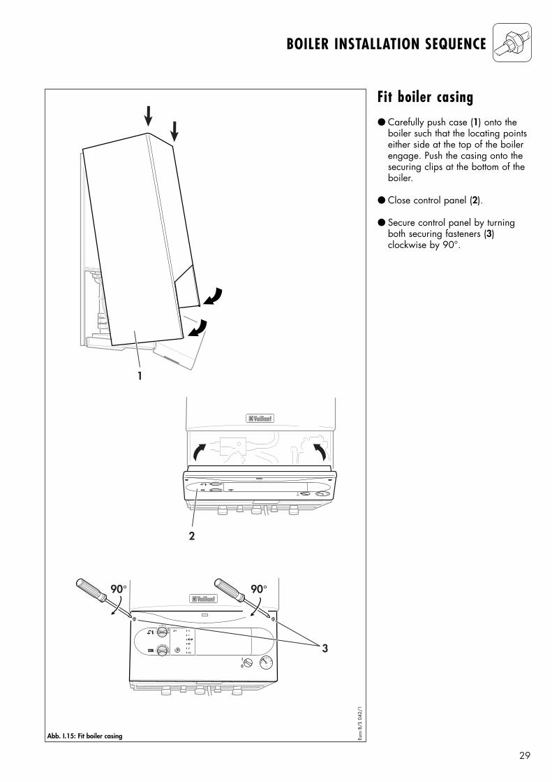
Fit boiler casing● Carefully push case (1) onto the
boiler such that the locating pointseither side at the top of the boilerengage. Push the casing onto thesecuring clips at the bottom of theboiler.
● Close control panel (2).
● Secure control panel by turningboth securing fasteners (3) clockwise by 90°.
1
I
0
I
0
90°90°
3
2
Abb. I.15: Fit boiler casing Euro
B/S
042
/1
30
COMMISSIONING PART I
Preliminary electricalchecksCheck the electrical installation bycarrying out short circuit, earth continuity and resistance to earth testsand a check for correct polarity.
Gas supplyThe complete gas installation including the gas meter must be inspected, tested for soundness andpurged in accordance with BS 6891.
The gas supply to the boiler can bepurged by slackening the gas servicevalve beneath the boiler. Ensure thatthere is adequate ventilation, extinguish all naked flames and donot smoke whilst purging.
After purging, the gas service valveconnection must be retightened andtested for soundness. (The boiler itselfdoes not require purging as this willbe done by the automatic burnersequence control).
Water supplyOpen all domestic hot water taps supplied by the boiler, turn on themains water supply to the boiler andopen the mains water isolating valvebelow the boiler.
Water will now flow through the boiler to the hot taps. Starting withthe lowest tap supplied, turn the hottaps off one at a time until the hotwater pipework is purged of air.
Check all hot and cold water pipework for leaks.

31
COMMISSIONING PART I
32
COMMISSIONING PART I
2
53
4
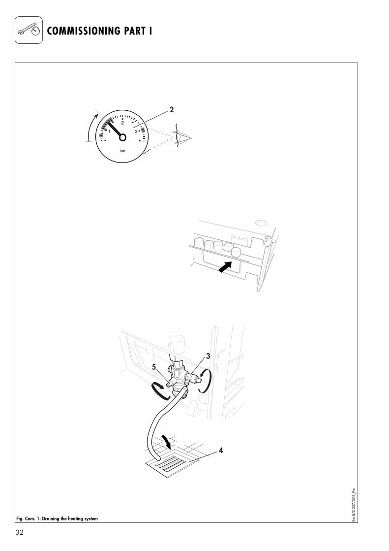
Fig. Com. 1: Draining the heating system Eor B
/S 2
07/0
GB_
Pro
33
COMMISSIONING PART I
Initial system flush(„cold“)The whole of the heating system mustbe flushed out at least twice: oncecold, and once hot as instructed lateron page 41.
Open all radiator or heating valvesand the boiler CH service valves anddrain the heating system and boilercompletely from the lowest points ofthe system via 1/2” BSP drain taps(opened full bore to remove anyinstallation debris prior to lighting theboiler).
Refill the heating system.
Check the operation of the pressurerelief valve by rotating the knob onthe valve.
Filling the heatingsystemProceed as follows to fill the system:
● Open all radiator valves on thesystem.
● Fill the system via the seperate filling point.
● Open the valve slowly and fill theunit with water until the requiredamount has been added (2).
● Bleed the air from the radiators.
● The boiler is equipped with anautomatic air release valve. Toallow this to vent the boiler, thecap top must be slackened by 1 - 2 turns. (This cap must be leftslackened during operation toensure any residual air or systemgases are released).
● Close the filling valve (1) and disconnect the temporary connection.
● Now check the water pressure inthe unit again (and add morewater if necessary).
34
GAS SUPPLY ADJUSTMENTS(COMMISSIONING PART II)
1
2
Euro
B/S
034
/0
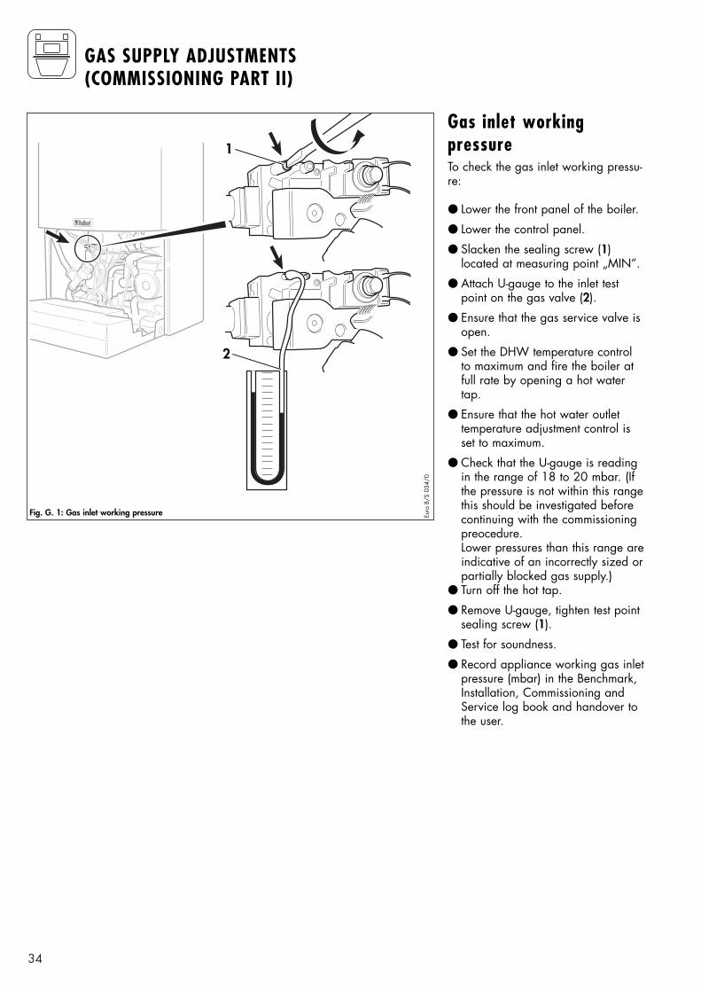
Gas inlet workingpressureTo check the gas inlet working pressu-re:
● Lower the front panel of the boiler.
● Lower the control panel.
● Slacken the sealing screw (1) located at measuring point „MIN”.
● Attach U-gauge to the inlet testpoint on the gas valve (2).
● Ensure that the gas service valve isopen.
● Set the DHW temperature controlto maximum and fire the boiler atfull rate by opening a hot watertap.
● Ensure that the hot water outlet temperature adjustment control isset to maximum.
● Check that the U-gauge is readingin the range of 18 to 20 mbar. (Ifthe pressure is not within this rangethis should be investigated beforecontinuing with the commissioningpreocedure.Lower pressures than this range areindicative of an incorrectly sized orpartially blocked gas supply.)
● Turn off the hot tap.
● Remove U-gauge, tighten test pointsealing screw (1).
● Test for soundness.
● Record appliance working gas inletpressure (mbar) in the Benchmark,Installation, Commissioning andService log book and handover tothe user.
Fig. G. 1: Gas inlet working pressure
35
GAS SUPPLY ADJUSTMENTS(COMMISSIONING PART II)
1a
1
3
2
3a
2a
Euro
B/S
035
/0
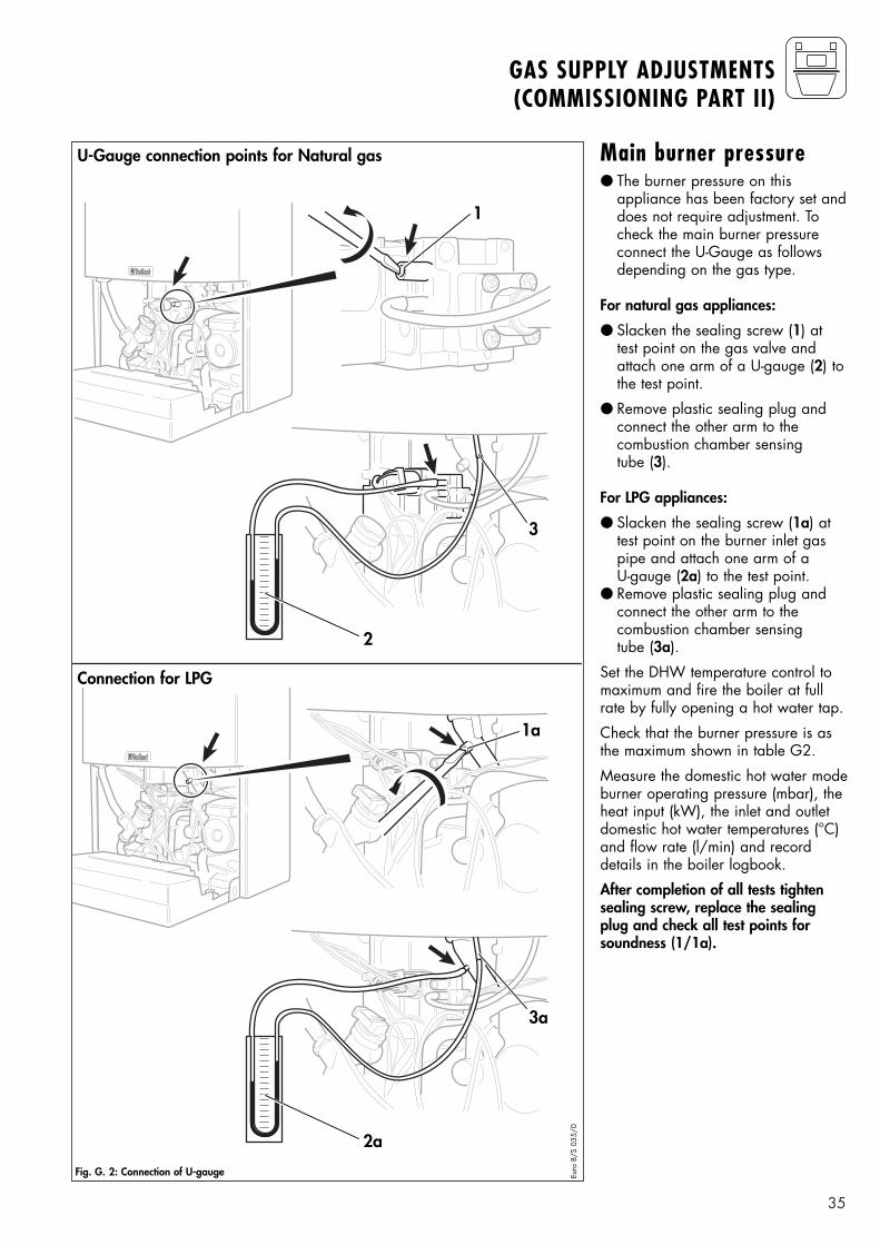
Main burner pressure● The burner pressure on this
appliance has been factory set anddoes not require adjustment. Tocheck the main burner pressureconnect the U-Gauge as follows depending on the gas type.
For natural gas appliances:
● Slacken the sealing screw (1) attest point on the gas valve andattach one arm of a U-gauge (2) tothe test point.
● Remove plastic sealing plug andconnect the other arm to thecombustion chamber sensing tube (3).
For LPG appliances:
● Slacken the sealing screw (1a) attest point on the burner inlet gaspipe and attach one arm of a U-gauge (2a) to the test point.
● Remove plastic sealing plug andconnect the other arm to the combustion chamber sensing tube (3a).
Set the DHW temperature control tomaximum and fire the boiler at fullrate by fully opening a hot water tap.
Check that the burner pressure is asthe maximum shown in table G2.
Measure the domestic hot water modeburner operating pressure (mbar), theheat input (kW), the inlet and outletdomestic hot water temperatures (°C)and flow rate (l/min) and recorddetails in the boiler logbook.
After completion of all tests tightensealing screw, replace the sealingplug and check all test points forsoundness (1/1a).
Fig. G. 2: Connection of U-gauge
U-Gauge connection points for Natural gas
Connection for LPG
36
GAS SUPPLY ADJUSTMENTS(COMMISSIONING PART II)
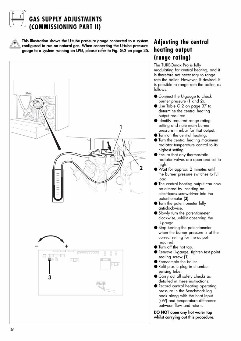
Adjusting the centralheating output (range rating)The TURBOmax Pro is fully modulating for central heating, and itis therefore not necessary to rangerate the boiler. However, if desired, itis possible to range rate the boiler, asfollows:
● Connect the U-gauge to check burner pressure (1 and 2).
● Use Table G.2 on page 37 to determine the central heating output required.
● Identify required range rating setting and note main burner pressure in mbar for that output.
● Turn on the central heating.● Turn the central heating maximum
radiator temperature control to itshighest setting.
● Ensure that any thermostatic radiator valves are open and set tohigh.
● Wait for approx. 2 minutes untilthe burner pressure switches to fullload.
● The central heating output can nowbe altered by inserting an electricans screwdriver into thepotentiometer (3).
● Turn the potentiometer fullyanticlockwise.
● Slowly turn the potentiometer clockwise, whilst observing the U-gauge.
● Stop turning the potentiometerwhen the burner pressure is at thecorrect setting for the output required.
● Turn off the hot tap.● Remove U-gauge, tighten test point
sealing screw (1).● Reassemble the boiler.● Refit plastic plug in chamber
sensing tube.● Carry out all safety checks as
detailed in these instructions.● Record central heating operating
pressure in the Benchmark logbook along with the heat input(kW) and temperature differencebetween flow and return.
DO NOT open any hot water tapwhilst carrying out this procedure.
This illustration shows the U-tube pressure gauge connected to a systemconfigured to run on natural gas. When connecting the U-tube pressuregauge to a system running on LPG, please refer to Fig. G.2 on page 35.
1
2
+-
3
37
GAS SUPPLY ADJUSTMENTS(COMMISSIONING PART II)
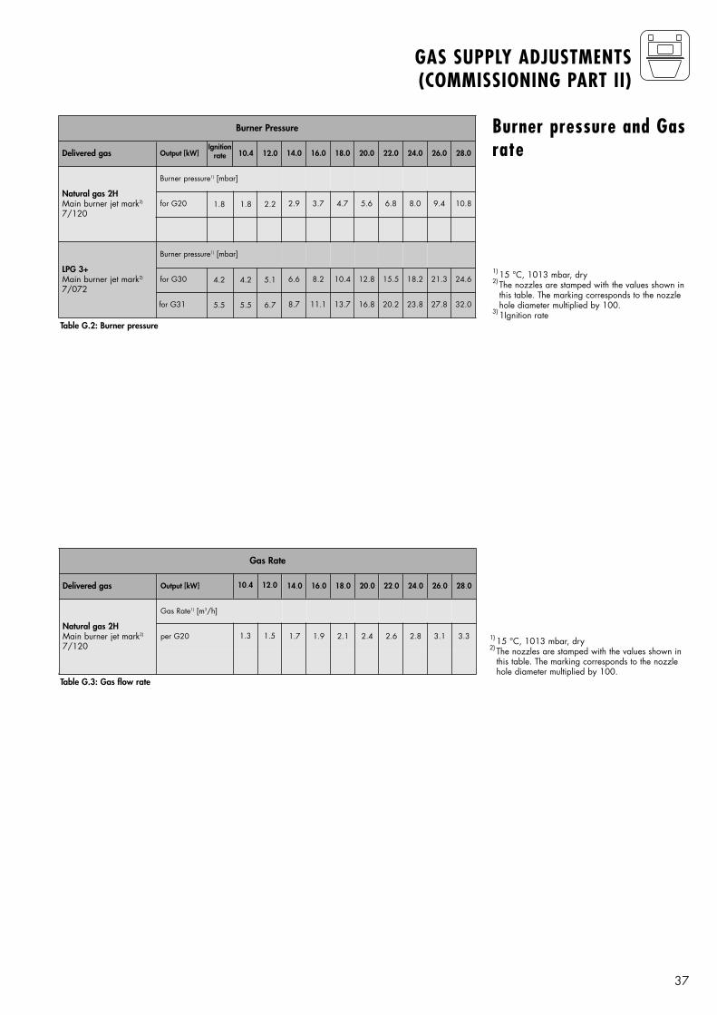
1) 15 °C, 1013 mbar, dry2) The nozzles are stamped with the values shown in
this table. The marking corresponds to the nozzlehole diameter multiplied by 100.
3) 1Ignition rate
1) 15 °C, 1013 mbar, dry2) The nozzles are stamped with the values shown in
this table. The marking corresponds to the nozzlehole diameter multiplied by 100.
Burner pressure and Gasrate
Table G.3: Gas flow rate
Table G.2: Burner pressure
Burner Pressure
Natural gas 2HMain burner jet mark2)
7/120
Burner pressure1) [mbar]
Delivered gas
for G20
Output [kW] 14.0 16.0 18.0 20.0 22.0 24.0 26.0 28.0
LPG 3+Main burner jet mark2)
7/072
2.9
Burner pressure1) [mbar]
3.7 4.7
for G30 6.6 8.2 10.4 12.8 15.5 18.2 21.3 24.6
5.6 6.8
for G31 8.7 11.1 13.7 16.8 20.2 23.8 27.8 32.0
8.0 9.4 10.8
12.0
2.2
10.4
1.81.8
Ignitionrate
5.1
6.7
4.2
5.5
4.2
5.5
Gas Rate
Natural gas 2HMain burner jet mark2)
7/120
Gas Rate1) [m3/h]
Delivered gas
per G20
Output [kW] 14.0 16.0 18.0 20.0 22.0 24.0 26.0 28.0
1.7 1.9 2.1 2.4 2.6 2.8 3.1 3.3
12.0
1.5
10.4
1.3
38
FUNCTIONAL CHECKS(COMMISSIONING PART III)
I
0
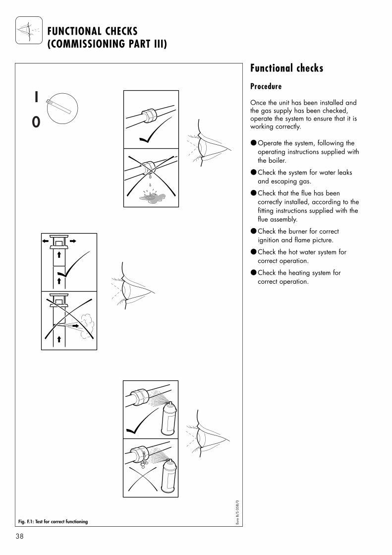
Functional checks
Procedure
Once the unit has been installed andthe gas supply has been checked,operate the system to ensure that it isworking correctly.
● Operate the system, following theoperating instructions supplied withthe boiler.
● Check the system for water leaksand escaping gas.
● Check that the flue has been correctly installed, according to thefitting instructions supplied with theflue assembly.
● Check the burner for correct ignition and flame picture.
● Check the hot water system for correct operation.
● Check the heating system for correct operation.
Fig. F.1: Test for correct functioning Euro
B/S
058
/0
39
FUNCTIONAL CHECKS(COMMISSIONING PART III)
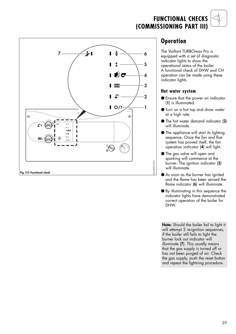
OperationThe Vaillant TURBOmax Pro is equipped with a set of diagnosticindicator lights to show the operational status of the boiler. A functional check of DHW and CHoperation can be made using theseindicator lights.
Hot water system● Ensure that the power on indicator
(1) is illuminated.
● Turn on a hot top and draw waterat a high rate.
● The hot water demand indicator (2)will illuminate.
● The appliance will start its lightingsequence. Once the fan and fluesystem has proved itself, the fanoperation indicator (4) will light.
● The gas valve will open andsparking will commence at the burner. The ignition indicator (5)will illuminate.
● As soon as the burner has ignitedand the flame has been sensed theflame indicator (6) will illuminate.
● By illuminating in this sequence theindicator lights have demonstratedcorrect operation of the boiler forDHW.
I
0
1
2
3
4
5
67
Fig. F.2: Functional check Euro
B/S
015
/1
Note: Should the boiler fail to light itwill attempt 2 re-ignition sequences,if the boiler still fails to light the burner lock out indicator will illuminate (7). This usually meansthat the gas supply is turned off orhas not been purged of air. Checkthe gas supply, push the reset buttonand repeat the lightning procedure.
40
FUNCTIONAL CHECKS(COMMISSIONING PART III)
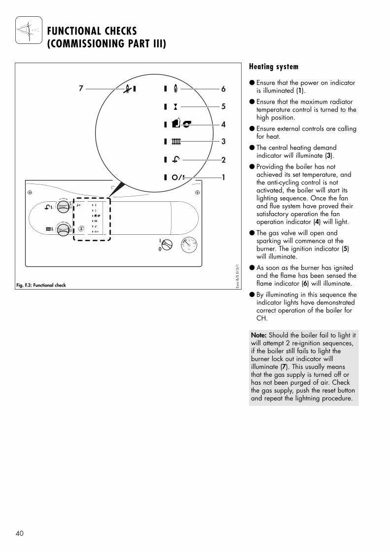
Heating system
● Ensure that the power on indicatoris illuminated (1).
● Ensure that the maximum radiatortemperature control is turned to thehigh position.
● Ensure external controls are callingfor heat.
● The central heating demand indicator will illuminate (3).
● Providing the boiler has not achieved its set temperature, andthe anti-cycling control is not activated, the boiler will start itslighting sequence. Once the fanand flue system have proved theirsatisfactory operation the fan operation indicator (4) will light.
● The gas valve will open and sparking will commence at the burner. The ignition indicator (5)will illuminate.
● As soon as the burner has ignitedand the flame has been sensed theflame indicator (6) will illuminate.
● By illuminating in this sequence theindicator lights have demonstratedcorrect operation of the boiler forCH.
Note: Should the boiler fail to light itwill attempt 2 re-ignition sequences,if the boiler still fails to light the burner lock out indicator will illuminate (7). This usually meansthat the gas supply is turned off orhas not been purged of air. Checkthe gas supply, push the reset buttonand repeat the lightning procedure.
I
0
1
2
3
4
5
67
Fig. F.3: Functional check Euro
B/S
015
/1
41
FUNCTIONAL CHECKS(COMMISSIONING PART III)
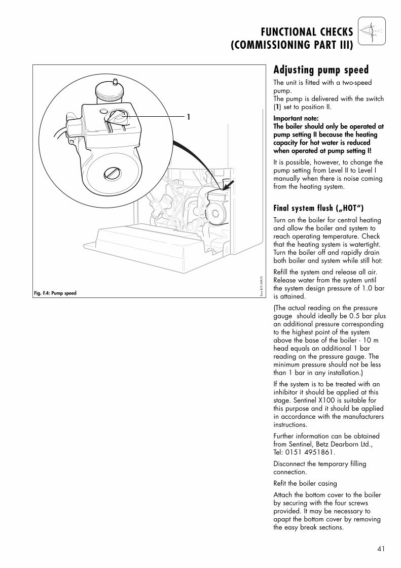
Adjusting pump speedThe unit is fitted with a two-speedpump.The pump is delivered with the switch(1) set to position II.
Important note: The boiler should only be operated atpump setting II because the heatingcapacity for hot water is reducedwhen operated at pump setting I!
It is possible, however, to change thepump setting from Level II to Level Imanually when there is noise comingfrom the heating system.
Final system flush („HOT“)Turn on the boiler for central heatingand allow the boiler and system toreach operating temperature. Checkthat the heating system is watertight.Turn the boiler off and rapidly drainboth boiler and system while still hot:
Refill the system and release all air.Release water from the system untilthe system design pressure of 1.0 baris attained.
(The actual reading on the pressuregauge should ideally be 0.5 bar plusan additional pressure correspondingto the highest point of the systemabove the base of the boiler - 10 mhead equals an additional 1 bar reading on the pressure gauge. Theminimum pressure should not be lessthan 1 bar in any installation.)
If the system is to be treated with aninhibitor it should be applied at thisstage. Sentinel X100 is suitable forthis purpose and it should be appliedin accordance with the manufacturersinstructions.
Further information can be obtainedfrom Sentinel, Betz Dearborn Ltd., Tel: 0151 4951861.
Disconnect the temporary fillingconnection.
Refit the boiler casing
Attach the bottom cover to the boilerby securing with the four screws provided. It may be necessary toapapt the bottom cover by removingthe easy break sections.
1
Fig. F.4: Pump speed Euro
B/S
049
/0
42
FUNCTIONAL CHECKS(COMMISSIONING PART III)
Set the maximum radiator temperaturecontrol to the desired setting.
Set the maximum hot water temperature control to the desired setting.
Instruct the user in the safe and efficient operation of the boiler, inparticular the function of
● The boiler on/off control
● The maximum radiator temperaturecontrol
● The maximum hot water temperature control
● The pressure gauge
Show the user how to operate anyexternal controls.
Explain to the user the importance ofhaving the boiler regularly servicedby a competent servicing company.To ensure regular servicing, it is strongly recommended that arrangements are made for aMaintenance Agreement. Pleasecontact Vaillant Service Solutions(0870 6060 777) for further details.
Ensure the boiler log book is fullycompleted and leave with the enduser. Failure to install and commissionthis appliance to the manufacturersinstructions may invaludate the warranty (Note: This does not affectyour statutory rights).
Leave the user instructions and theboiler log book in the clips providedin the front panel of the boiler.
Leave the installation and servicinginstructions with the user.
Note: fit theBenchmark log bookunder the users instructions.
Handing over to the user
SERVICING
43
Before commencing any servicing ormaintenance work, carry out an initialinspection of the system as follows:
● Inspect the flue, pipework and electrical connections for indications of damage or deterioration.
● Inspect the air supply and ventilation arrangements of theinstallation.
● Check the heating and watersystem, in particular the conditionof radiator valves, evidence of leakage from the heating systemand dripping hot water taps.
Functional check of boiler operation
● Carry out a functional check of theboiler operation as prevoiuslydetailed.
● Remove the appliance casing asdetailed on page 20 and operatethe boiler by fully opening a hotwater tap. Inspect the burner operation through the viewing window. Check that the flames areevenly covering the surface of theburner. Inspect for signs of excessive flame lift or sooting.
Initial Inspection To ensure the continued safe and efficient operation of the boiler it isrecommended that it is checked andserviced as necessary at regular intervals. The frequency of servicingwill depend upon the particular installation conditions and usage, butin general once per year should beadequate. It is the law that all ser-vicing work is carried out by a com-petent person (Corgi registered).
Important: Before starting any maintenance work:
● Isolate the mains electricity supplyby disconnecting the plug at thesocket outlet (if there is only an isolating switch remove the fusefrom the switch).
● Turn OFF the gas supply at the gasservice valve fitted to the boiler.
● Always test for gas soundness andalways carry out functional checksafter any service work and afterexchanging any gas carrying component.
● Always check earth continuity,polarity and resistance to earthwith a multimeter after any servicework and after exchanging anyelectrical component.
Note: The boiler is fitted with a combustion analysis test point. A suitable combustion analyser can beconnected to this point to establishthe combustion performance of theboiler.
44
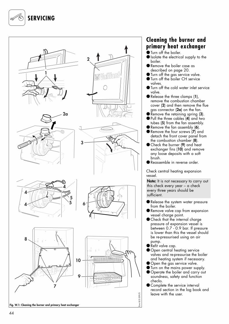
SERVICING
Cleaning the burner andprimary heat exchanger● Turn off the boiler.● Isolate the electrical supply to the
boiler.● Remove the boiler case as
described on page 20.● Turn off the gas service valve.● Turn off the boiler CH service
valves.● Turn off the cold water inlet service
valve.● Release the three clamps (1),
remove the combustion chambercover (2) and then remove the fluegas connector (2a) on the fan.
● Remove the retaining spring (3).● Pull the three cables (4) and two
tubes (5) from the fan assembly.● Remove the fan assembly (6).● Remove the four screws (7) and
detach the front cover panel fromthe combustion chamber (8).
● Check the burner (9) and heatexchanger fins (10) and removeany loose deposits with a softbrush.
● Reassemble in reverse order.
Check central heating expansion vessel.
● Release the system water pressurefrom the boiler.
● Remove valve cap from expansionvessel charge point.
● Check that the internal charge pressure of expansion vessel is between 0.7 - 0.9 bar. If pressureis lower than this the vessel shouldbe re-pressurised using an airpump.
● Refit valve cap.● Open central heating service
valves and re-pressurise the boilerand heating system if necessary.
● Open the gas service valve.● Turn on the mains power supply.● Operate the boiler and carry out
soundness, safety and functionchecks.
● Complete the service intervalrecord section in the log book andleave with the user.
64
44
55
7
9
10
8
1
2
3
2a
Fig. W.1: Cleaning the burner and primary heat exchanger Euro
B/S
059
/0
Note: It is not necessary to carry outthis check every year – a checkevery three years should be sufficient.
45
PARTS REPLACEMENT
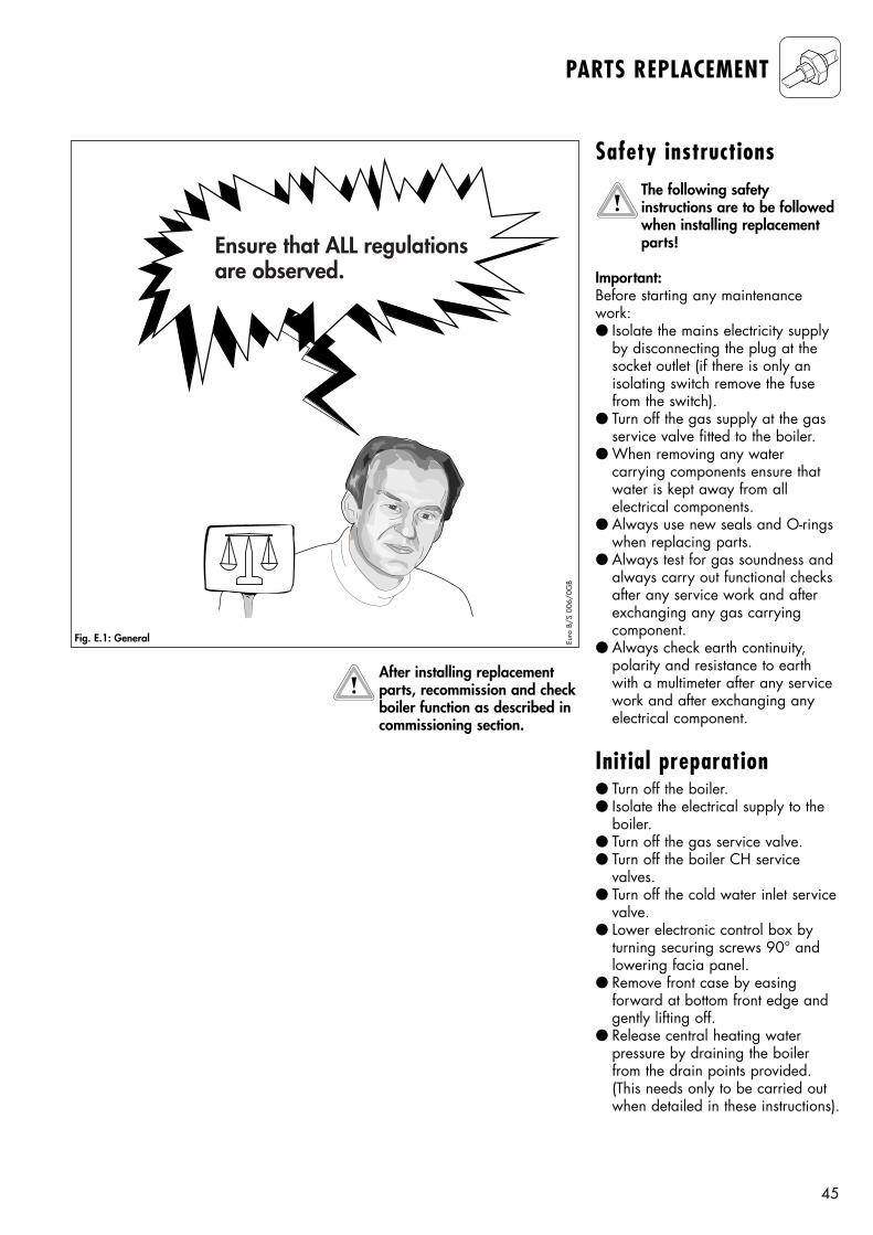
Ensure that ALL regulationsare observed.
Fig. E.1: General Euro
B/S
006
/0G
B
Safety instructions The following safety instructions are to be followedwhen installing replacementparts!
Important:Before starting any maintenancework:● Isolate the mains electricity supply
by disconnecting the plug at thesocket outlet (if there is only an isolating switch remove the fusefrom the switch).
● Turn off the gas supply at the gasservice valve fitted to the boiler.
● When removing any water carrying components ensure thatwater is kept away from all electrical components.
● Always use new seals and O-ringswhen replacing parts.
● Always test for gas soundness andalways carry out functional checksafter any service work and afterexchanging any gas carrying component.
● Always check earth continuity,polarity and resistance to earthwith a multimeter after any servicework and after exchanging anyelectrical component.
Initial preparation● Turn off the boiler.● Isolate the electrical supply to the
boiler.● Turn off the gas service valve.● Turn off the boiler CH service
valves. ● Turn off the cold water inlet service
valve. ● Lower electronic control box by
turning securing screws 90° andlowering facia panel.
● Remove front case by easing forward at bottom front edge andgently lifting off.
● Release central heating water pressure by draining the boilerfrom the drain points provided.(This needs only to be carried outwhen detailed in these instructions).
After installing replacementparts, recommission and checkboiler function as described in commissioning section.
46
1
3 4
5
2
Euro
B/S
158
/1
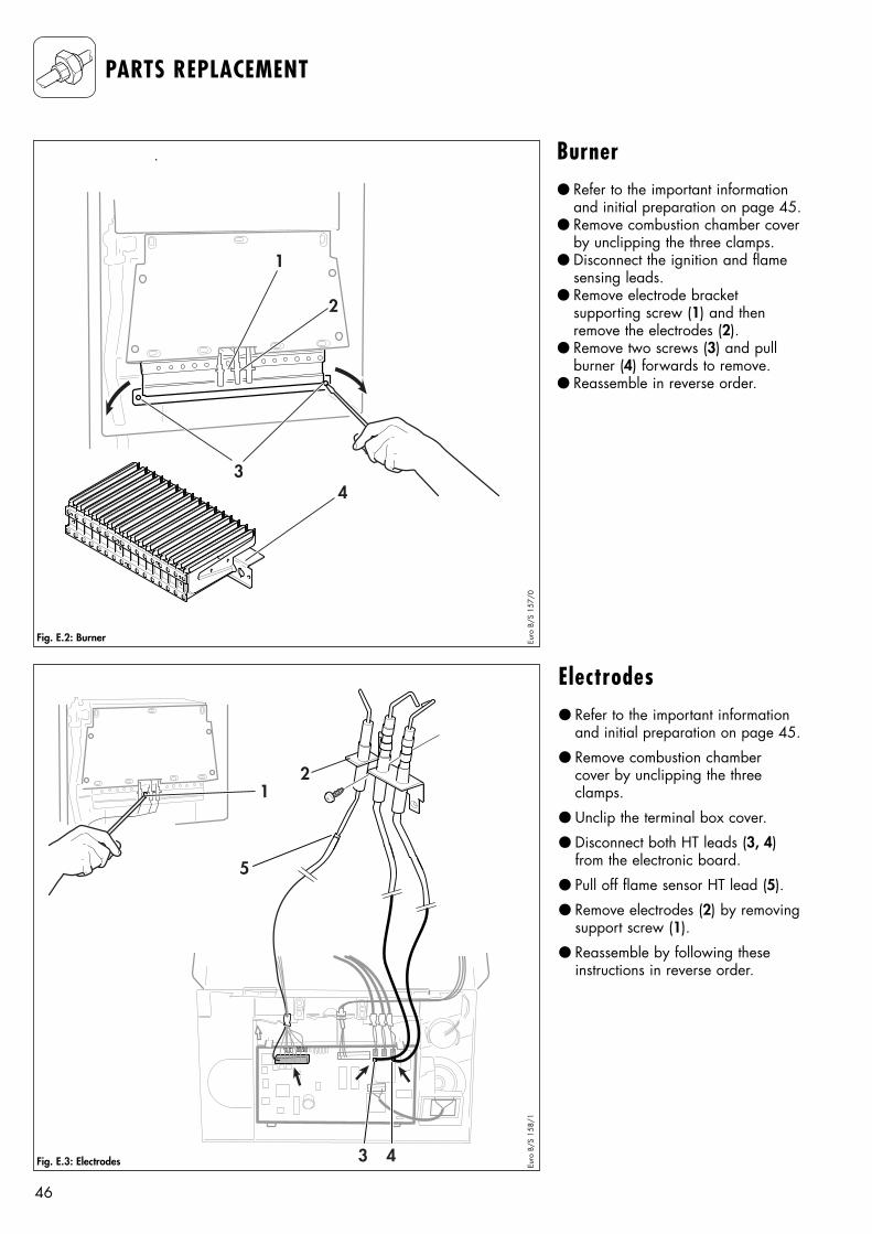
Electrodes● Refer to the important information
and initial preparation on page 45.
● Remove combustion chambercover by unclipping the threeclamps.
● Unclip the terminal box cover.
● Disconnect both HT leads (3, 4)from the electronic board.
● Pull off flame sensor HT lead (5).
● Remove electrodes (2) by removingsupport screw (1).
● Reassemble by following theseinstructions in reverse order.
PARTS REPLACEMENT
3
21
2
4
Fig. E.2: Burner Euro
B/S
157
/0
Fig. E.3: Electrodes
Burner● Refer to the important information
and initial preparation on page 45.● Remove combustion chamber cover
by unclipping the three clamps.● Disconnect the ignition and flame
sensing leads.● Remove electrode bracket
supporting screw (1) and thenremove the electrodes (2).
● Remove two screws (3) and pullburner (4) forwards to remove.
● Reassemble in reverse order.
47
PARTS REPLACEMENT
1
2
4
3
8
9
5
76
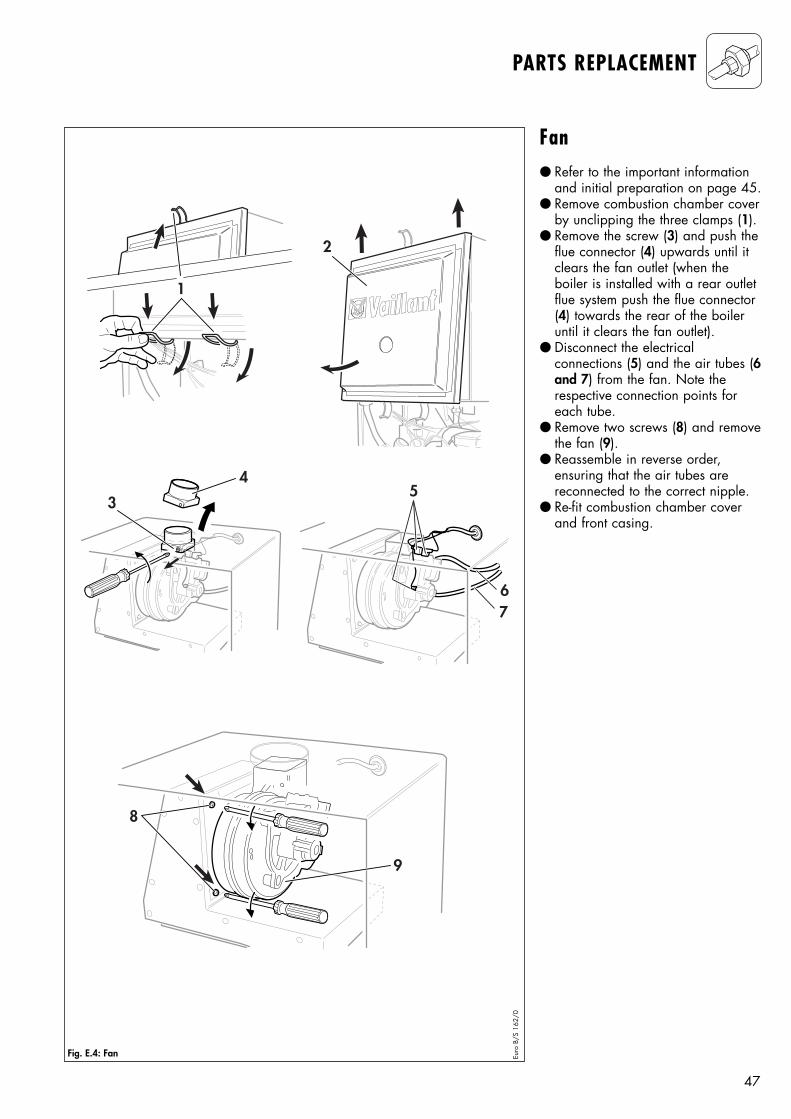
Fig. E.4: Fan Euro
B/S
162
/0
Fan● Refer to the important information
and initial preparation on page 45.● Remove combustion chamber cover
by unclipping the three clamps (1).● Remove the screw (3) and push the
flue connector (4) upwards until itclears the fan outlet (when the boiler is installed with a rear outletflue system push the flue connector(4) towards the rear of the boileruntil it clears the fan outlet).
● Disconnect the electrical connections (5) and the air tubes (6and 7) from the fan. Note the respective connection points foreach tube.
● Remove two screws (8) and removethe fan (9).
● Reassemble in reverse order, ensuring that the air tubes arereconnected to the correct nipple.
● Re-fit combustion chamber coverand front casing.
48
3
1
2
65
7
4
Euro
B/S
297
/0
9 10
813
14
11
12
Euro
B/S
298
/0
PARTS REPLACEMENT
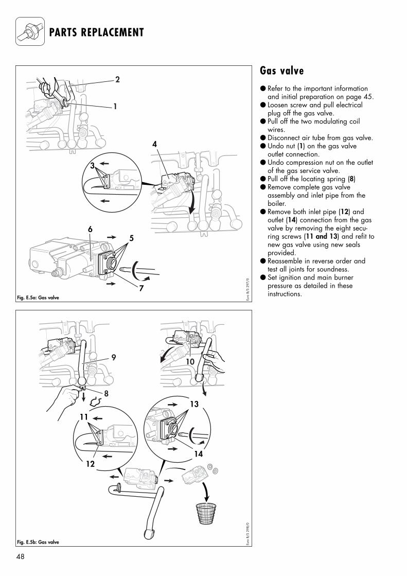
Fig. E.5a: Gas valve
Fig. E.5b: Gas valve
Gas valve● Refer to the important information
and initial preparation on page 45.● Loosen screw and pull electrical
plug off the gas valve.● Pull off the two modulating coil
wires.● Disconnect air tube from gas valve.● Undo nut (1) on the gas valve
outlet connection.● Undo compression nut on the outlet
of the gas service valve.● Pull off the locating spring (8)● Remove complete gas valve
assembly and inlet pipe from theboiler.
● Remove both inlet pipe (12) andoutlet (14) connection from the gasvalve by removing the eight secu-ring screws (11 and 13) and refit tonew gas valve using new seals provided.
● Reassemble in reverse order andtest all joints for soundness.
● Set ignition and main burner pressure as detailed in theseinstructions.
49
PARTS REPLACEMENT
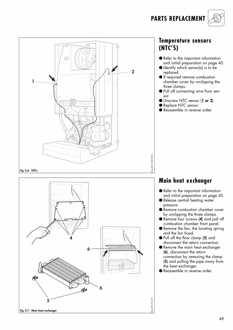
Temperature sensors(NTC’S)● Refer to the important information
and initial preparation on page 45.● Identify which sensor(s) is to be
replaced.● If required remove combustion
chamber cover by unclipping thethree clamps.
● Pull off connecting wire from sen-sor.
● Unscrew NTC sensor (1 or 2).● Replace NTC sensor.● Reassemble in reverse order.
Main heat exchanger● Refer to the important information
and initial preparation on page 45.● Release central heating water
pressure.● Remove combustion chamber cover
by unclipping the three clamps.● Remove four screws (4) and pull off
combustion chamber front panel.● Remove the fan, the locating spring
and the fan hood.● Pull off the flow clamp (5) and
disconnect the return connection.● Remove the main heat exchanger
(6), disconnect the return connection by removing the clamp(5) and pulling the pipe away fromthe heat exchanger.
● Reassemble in reverse order.
2
1
Fig. E.6: NTCs Euro
B/S
163
/0_P
ro
4
6
6
5
Fig. E.7: Main heat exchanger Euro
B/S
161
/0
50
PARTS REPLACEMENT
1
4
2
3
Fig. E.8: Expansion vessel Euro
B/S
164
/0
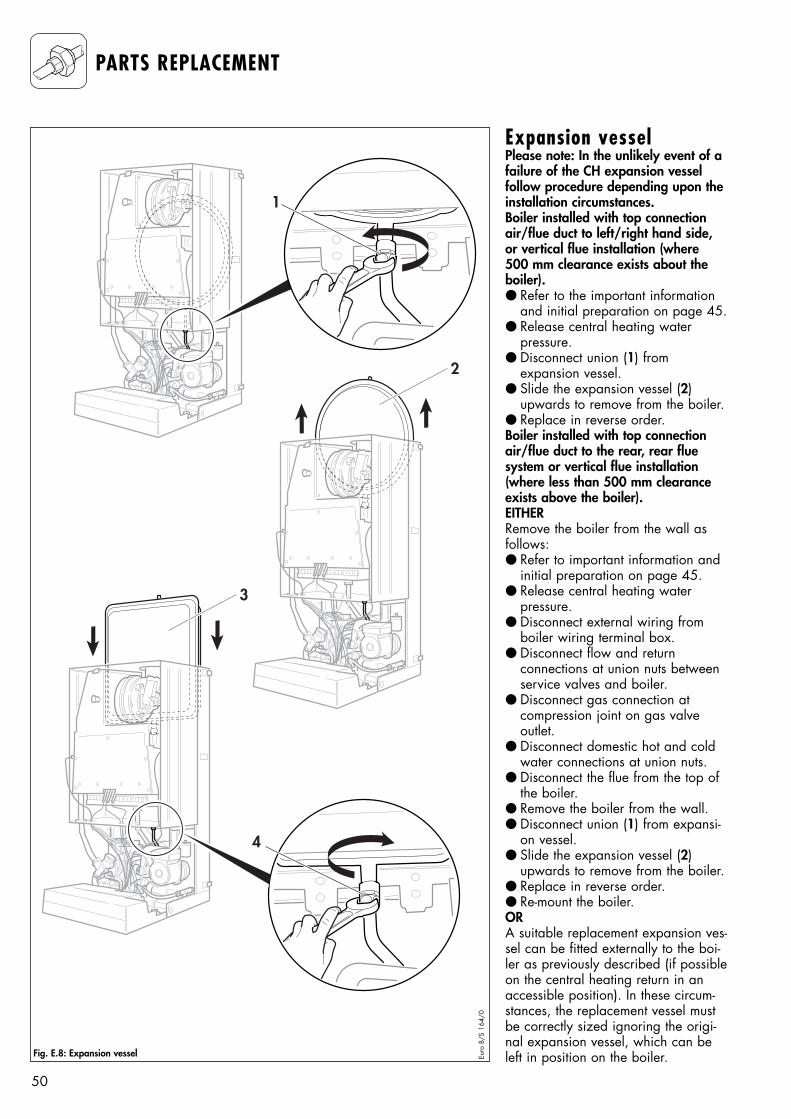
Expansion vesselPlease note: In the unlikely event of afailure of the CH expansion vessel follow procedure depending upon theinstallation circumstances.Boiler installed with top connectionair/flue duct to left/right hand side,or vertical flue installation (where 500 mm clearance exists about theboiler).● Refer to the important information
and initial preparation on page 45.● Release central heating water
pressure.● Disconnect union (1) from
expansion vessel.● Slide the expansion vessel (2)
upwards to remove from the boiler.● Replace in reverse order.Boiler installed with top connectionair/flue duct to the rear, rear fluesystem or vertical flue installation(where less than 500 mm clearanceexists above the boiler).EITHERRemove the boiler from the wall asfollows:● Refer to important information and
initial preparation on page 45.● Release central heating water
pressure.● Disconnect external wiring from
boiler wiring terminal box.● Disconnect flow and return
connections at union nuts betweenservice valves and boiler.
● Disconnect gas connection at compression joint on gas valve outlet.
● Disconnect domestic hot and coldwater connections at union nuts.
● Disconnect the flue from the top ofthe boiler.
● Remove the boiler from the wall.● Disconnect union (1) from expansi-
on vessel.● Slide the expansion vessel (2)
upwards to remove from the boiler.● Replace in reverse order.● Re-mount the boiler.ORA suitable replacement expansion ves-sel can be fitted externally to the boi-ler as previously described (if possibleon the central heating return in anaccessible position). In these circum-stances, the replacement vessel mustbe correctly sized ignoring the origi-nal expansion vessel, which can beleft in position on the boiler.
51
PARTS REPLACEMENT
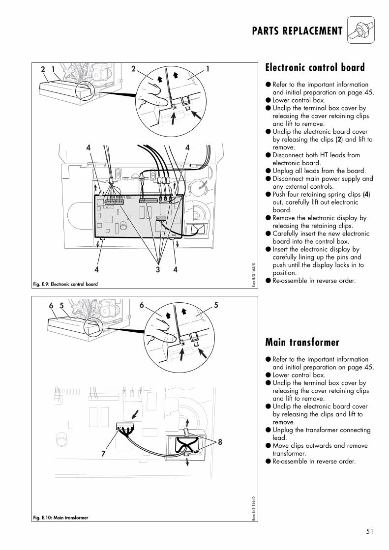
Electronic control board● Refer to the important information
and initial preparation on page 45.● Lower control box. ● Unclip the terminal box cover by
releasing the cover retaining clipsand lift to remove.
● Unclip the electronic board coverby releasing the clips (2) and lift toremove.
● Disconnect both HT leads fromelectronic board.
● Unplug all leads from the board.● Disconnect main power supply and
any external controls. ● Push four retaining spring clips (4)
out, carefully lift out electronicboard.
● Remove the electronic display byreleasing the retaining clips.
● Carefully insert the new electronicboard into the control box.
● Insert the electronic display bycarefully lining up the pins andpush until the display locks in toposition.
● Re-assemble in reverse order.
Main transformer● Refer to the important information
and initial preparation on page 45.● Lower control box. ● Unclip the terminal box cover by
releasing the cover retaining clipsand lift to remove.
● Unclip the electronic board coverby releasing the clips and lift toremove.
● Unplug the transformer connectinglead.
● Move clips outwards and removetransformer.
● Re-assemble in reverse order.
34 4
44
12 2 1
Fig. E.9: Electronic control board Euro
B/S
165
/0
56 6 5
78
Fig. E.10: Main transformer Euro
B/S
166
/0
52
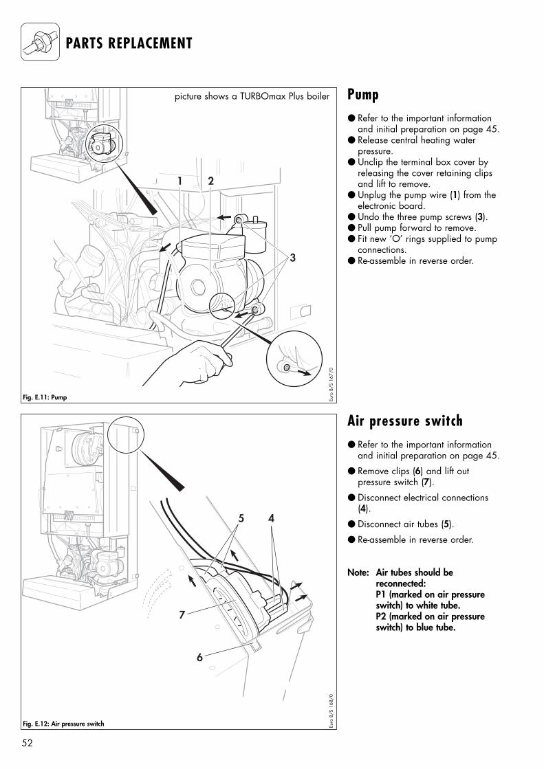
Air pressure switch● Refer to the important information
and initial preparation on page 45.
● Remove clips (6) and lift out pressure switch (7).
● Disconnect electrical connections(4).
● Disconnect air tubes (5).
● Re-assemble in reverse order.
Note: Air tubes should be reconnected:P1 (marked on air pressureswitch) to white tube.P2 (marked on air pressureswitch) to blue tube.
4
7
5
6
Euro
B/S
168
/0
Pump● Refer to the important information
and initial preparation on page 45.● Release central heating water
pressure.● Unclip the terminal box cover by
releasing the cover retaining clipsand lift to remove.
● Unplug the pump wire (1) from theelectronic board.
● Undo the three pump screws (3).● Pull pump forward to remove.● Fit new ‘O’ rings supplied to pump
connections.● Re-assemble in reverse order.3
21
Fig. E.11: Pump Euro
B/S
167
/0
Fig. E.12: Air pressure switch
PARTS REPLACEMENT
picture shows a TURBOmax Plus boiler
53
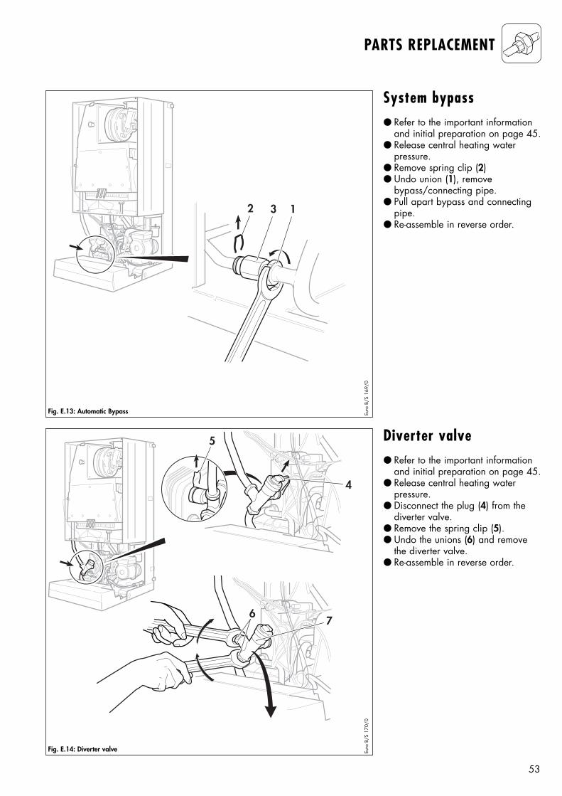
System bypass● Refer to the important information
and initial preparation on page 45.● Release central heating water
pressure.● Remove spring clip (2)● Undo union (1), remove
bypass/connecting pipe. ● Pull apart bypass and connecting
pipe.● Re-assemble in reverse order.
Diverter valve● Refer to the important information
and initial preparation on page 45.● Release central heating water
pressure.● Disconnect the plug (4) from the
diverter valve.● Remove the spring clip (5).● Undo the unions (6) and remove
the diverter valve.● Re-assemble in reverse order.
32 1
Fig. E.13: Automatic Bypass Euro
B/S
169
/0
4
5
67
Fig. E.14: Diverter valve Euro
B/S
170
/0
PARTS REPLACEMENT
54
PARTS REPLACEMENT
2
2
1
Fig. E.15: Pressure gauge Euro
B/S
171/
0
1
4
63
5
Fig. E.16: Aqua sensor Euro
B/S
172
/0G
B_Pr
o
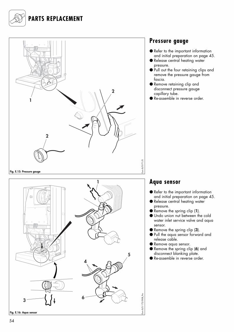
Pressure gauge● Refer to the important information
and initial preparation on page 45.● Release central heating water
pressure.● Pull out the four retaining clips and
remove the pressure gauge fromfascia.
● Remove retaining clip and disconnect pressure gauge capillary tube.
● Re-assemble in reverse order.
Aqua sensor● Refer to the important information
and initial preparation on page 45.● Release central heating water
pressure.● Remove the spring clip (1).● Undo union nut between the cold
water inlet service valve and aquasensor.
● Remove the spring clip (3).● Pull the aqua sensor forward and
release cable.● Remove aqua sensor.● Remove the spring clip (6) and
disconnect blanking plate.● Re-assemble in reverse order.
55
PARTS REPLACEMENT
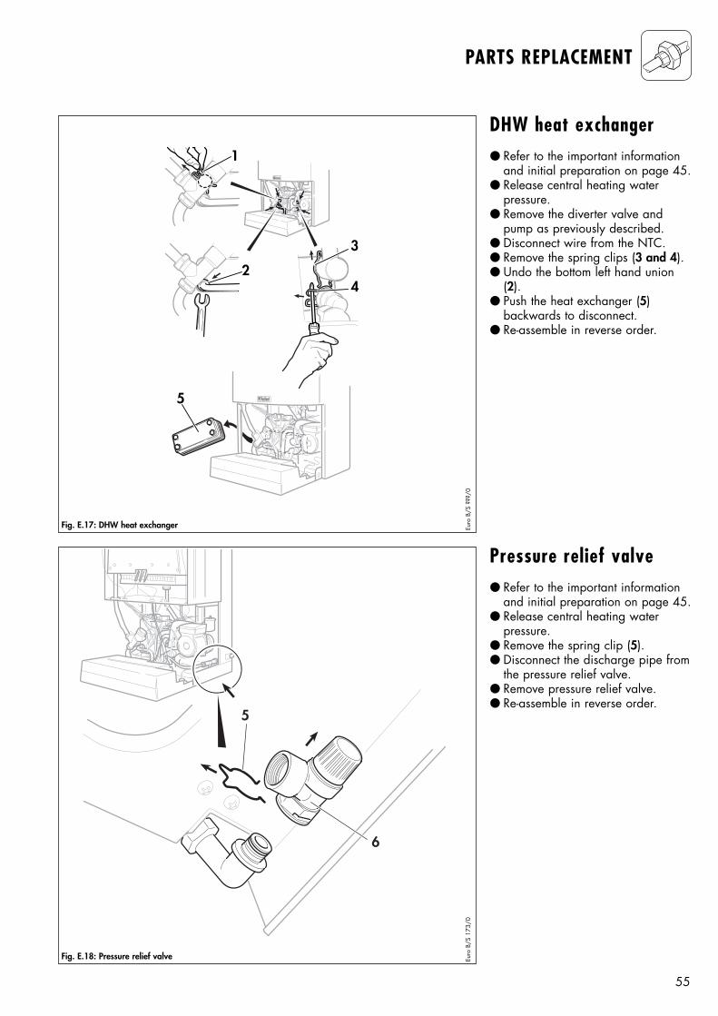
DHW heat exchanger ● Refer to the important information
and initial preparation on page 45.● Release central heating water
pressure.● Remove the diverter valve and
pump as previously described.● Disconnect wire from the NTC.● Remove the spring clips (3 and 4).● Undo the bottom left hand union
(2).● Push the heat exchanger (5)
backwards to disconnect.● Re-assemble in reverse order.
Pressure relief valve ● Refer to the important information
and initial preparation on page 45.● Release central heating water
pressure.● Remove the spring clip (5).● Disconnect the discharge pipe from
the pressure relief valve.● Remove pressure relief valve.● Re-assemble in reverse order.
5
1
2
3
4
Fig. E.17: DHW heat exchanger Euro
B/S
???
/0
6
5
Fig. E.18: Pressure relief valve Euro
B/S
173
/0
56
I
0
Fig. E.19: Functional check Euro
B/S
058
/0
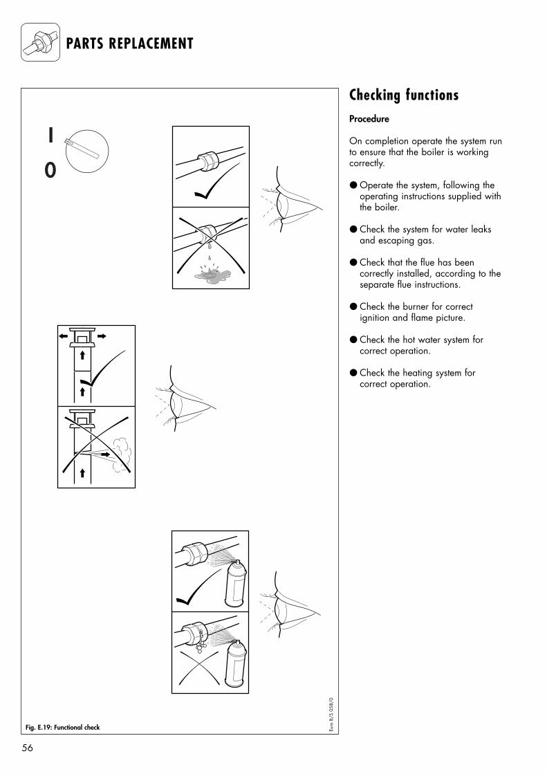
Checking functionsProcedure
On completion operate the system runto ensure that the boiler is workingcorrectly.
● Operate the system, following theoperating instructions supplied withthe boiler.
● Check the system for water leaksand escaping gas.
● Check that the flue has been correctly installed, according to theseparate flue instructions.
● Check the burner for correct ignition and flame picture.
● Check the hot water system for correct operation.
● Check the heating system for correct operation.
PARTS REPLACEMENT
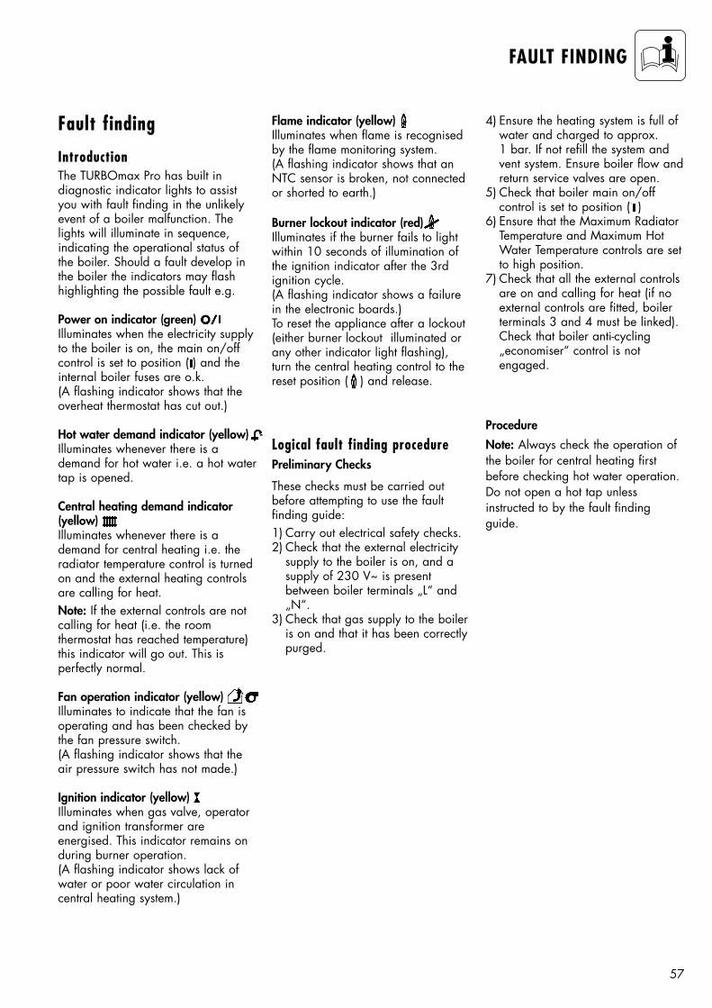
57
FAULT FINDING
Flame indicator (yellow)Illuminates when flame is recognisedby the flame monitoring system.(A flashing indicator shows that anNTC sensor is broken, not connectedor shorted to earth.)
Burner lockout indicator (red)Illuminates if the burner fails to lightwithin 10 seconds of illumination ofthe ignition indicator after the 3rdignition cycle.(A flashing indicator shows a failurein the electronic boards.)To reset the appliance after a lockout(either burner lockout illuminated orany other indicator light flashing),turn the central heating control to thereset position ( ) and release.
Fault finding
IntroductionThe TURBOmax Pro has built in diagnostic indicator lights to assistyou with fault finding in the unlikelyevent of a boiler malfunction. Thelights will illuminate in sequence, indicating the operational status ofthe boiler. Should a fault develop inthe boiler the indicators may flashhighlighting the possible fault e.g.
Power on indicator (green)Illuminates when the electricity supplyto the boiler is on, the main on/offcontrol is set to position ( ) and theinternal boiler fuses are o.k.(A flashing indicator shows that theoverheat thermostat has cut out.)
Hot water demand indicator (yellow)Illuminates whenever there is ademand for hot water i.e. a hot watertap is opened.
Central heating demand indicator (yellow)Illuminates whenever there is ademand for central heating i.e. theradiator temperature control is turnedon and the external heating controlsare calling for heat.Note: If the external controls are notcalling for heat (i.e. the room thermostat has reached temperature)this indicator will go out. This is perfectly normal.
Fan operation indicator (yellow)Illuminates to indicate that the fan isoperating and has been checked bythe fan pressure switch.(A flashing indicator shows that theair pressure switch has not made.)
Ignition indicator (yellow)Illuminates when gas valve, operatorand ignition transformer are energised. This indicator remains onduring burner operation.(A flashing indicator shows lack ofwater or poor water circulation incentral heating system.)
Logical fault finding procedurePreliminary Checks
These checks must be carried outbefore attempting to use the fault finding guide:1) Carry out electrical safety checks.2) Check that the external electricity
supply to the boiler is on, and asupply of 230 V~ is present between boiler terminals „L“ and„N“.
3) Check that gas supply to the boileris on and that it has been correctlypurged.
4) Ensure the heating system is full ofwater and charged to approx.1 bar. If not refill the system andvent system. Ensure boiler flow andreturn service valves are open.
5) Check that boiler main on/off control is set to position ( )
6) Ensure that the Maximum RadiatorTemperature and Maximum HotWater Temperature controls are setto high position.
7) Check that all the external controlsare on and calling for heat (if noexternal controls are fitted, boilerterminals 3 and 4 must be linked).Check that boiler anti-cycling „economiser“ control is not engaged.
Procedure
Note: Always check the operation ofthe boiler for central heating firstbefore checking hot water operation.Do not open a hot tap unless instructed to by the fault findingguide.
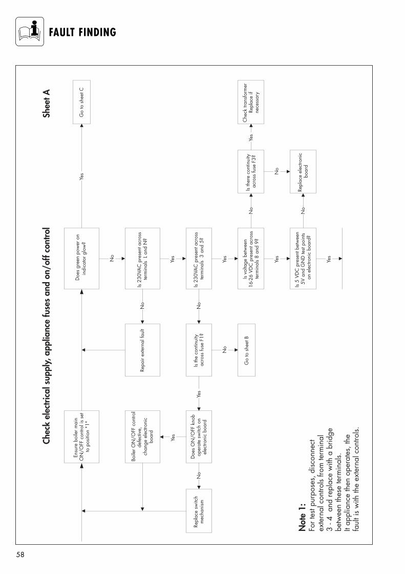
58
FAULT FINDING
Ensu
re b
oile
r mai
nO
N/O
FF c
ontro
l is
set
to p
ositi
on "
1"
Yes
Go
to s
heet
C
Chec
k el
ectri
cal s
uppl
y, a
pplia
nce
fuse
s an
d on
/off
cont
rol
No
Is 23
0VA
C p
rese
nt a
cros
ste
rmin
als
L a
nd N
?
Yes
Is 23
0VA
C p
rese
nt a
cros
ste
rmin
als
3 a
nd 5
?
Yes
Is vo
ltage
bet
wee
n16
-26
VDC
pre
sent
acr
oss
term
inal
s 8
and
9?
Yes
Is 5
VDC
pre
sent
bet
wee
n5V
and
GN
D te
st po
ints
on e
lect
roni
c bo
ard?
Repl
ace
LCD
disp
lay
Yes
No
Repa
ir ex
tern
al fa
ult
Is th
e co
ntin
uity
acro
ss fu
se F
1?
Go
to s
heet
B
Doe
s O
N/O
FF k
nob
oper
ate
switc
h on
elec
troni
c bo
ard
Boile
r ON
/OFF
con
trol
defe
ctiv
e, c
hang
e el
ectro
nic
boar
d
Repl
ace
switc
hm
echa
nism
No
No
No
Yes
Yes
Not
e 1:
For t
est p
urpo
ses,
disc
onne
ctex
tern
al c
ontro
ls fro
m te
rmin
al3
- 4 a
nd re
plac
e w
ith a
brid
gebe
twee
n th
ese
term
inal
s.It
appl
ianc
e th
en o
pera
tes,
the
faul
t is
with
the
exte
rnal
con
trols.
Shee
t A
Is th
ere
cont
inui
tyac
ross
fuse
F3?
No
No
Repl
ace
elec
troni
cbo
ard
No
Che
ck tr
ansfo
rmer
Repl
ace
ifne
cess
ary
Yes
Doe
s gr
een
pow
er o
nin
dica
tor g
low
?
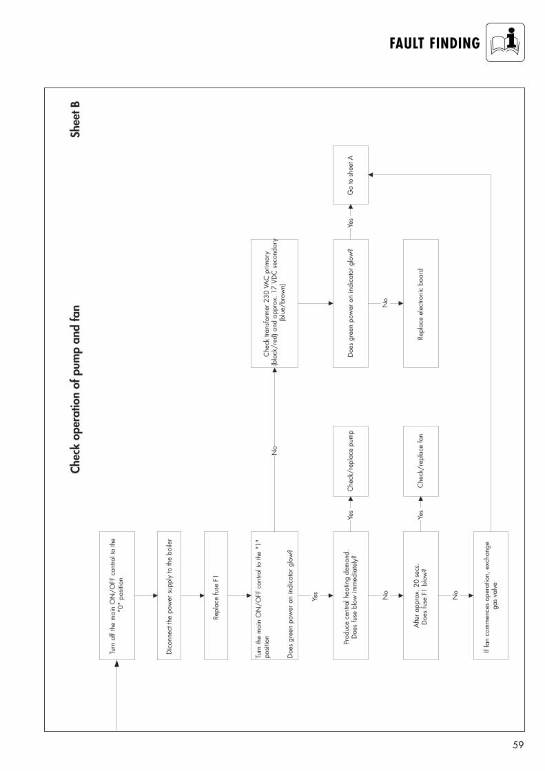
59
FAULT FINDING
Shee
t BCh
eck
oper
atio
n of
pum
p an
d fa
n
Turn
off
the
mai
n O
N/O
FF c
ontro
l to
the
"0"
posit
ion
Dic
onne
ct th
e po
wer
sup
ply
to th
e bo
iler
Go
to s
heet
A
Che
ck tr
ansfo
rmer
230
VA
C p
rimar
y(b
lack
/red
) and
app
rox.
17
VDC
sec
onda
ry(b
lue/
brow
n)
Che
ck/r
epla
ce p
ump
Repl
ace
fuse
F1
If fa
n co
mm
ence
s op
erat
ion,
exc
hang
ega
s va
lve
Afte
r app
rox.
20
secs
.D
oes
fuse
F1
blow
?
Prod
uce
cent
ral h
eatin
g de
man
d.D
oes
fuse
blo
w im
med
iate
ly?
Turn
the
mai
n O
N/O
FF c
ontro
l to
the
"1"
posit
ion
Doe
s gr
een
pow
er o
n in
dica
tor g
low
?
Yes
No
No
No
Yes
Che
ck/r
epla
ce fa
nRe
plac
e el
ectro
nic
boar
d
No
Yes
Yes
Doe
s gr
een
pow
er o
n in
dica
tor g
low
?
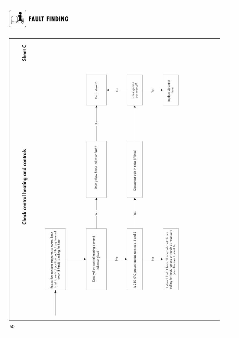
60
FAULT FINDINGCh
eck
cent
ral h
eatin
g an
d co
ntro
ls
Ensu
re th
at ra
diat
or te
mpe
ratu
re c
ontro
l kno
bis
set t
o ve
rtica
l pos
ition
and
that
any
inte
rnal
timer
(if f
itted
) is
calli
ng fo
r hea
t
No
Is 23
0 VA
C p
rese
nt a
cros
s te
rmin
als
4 an
d 5
No
Exte
rnal
faul
t: C
heck
all
exte
rnal
con
trols
are
calli
ng fo
r hea
t, re
plac
e or
repa
ir as
nec
essa
ry(s
ee a
lso n
ote
1 sh
eet A
)
Yes
Yes
Disc
onne
ct b
uilt
in ti
mer
(if f
itted
)
No
Go
to s
heet
D
Doe
s ig
nitio
nco
mm
ence
?
No
Yes
Repl
ace
defe
ctiv
etim
er
Shee
t C
Doe
s ye
llow
cen
tral h
eatin
g de
man
din
dica
tor g
low
? D
oes
yello
w fl
ame
indi
cato
r fla
sh?
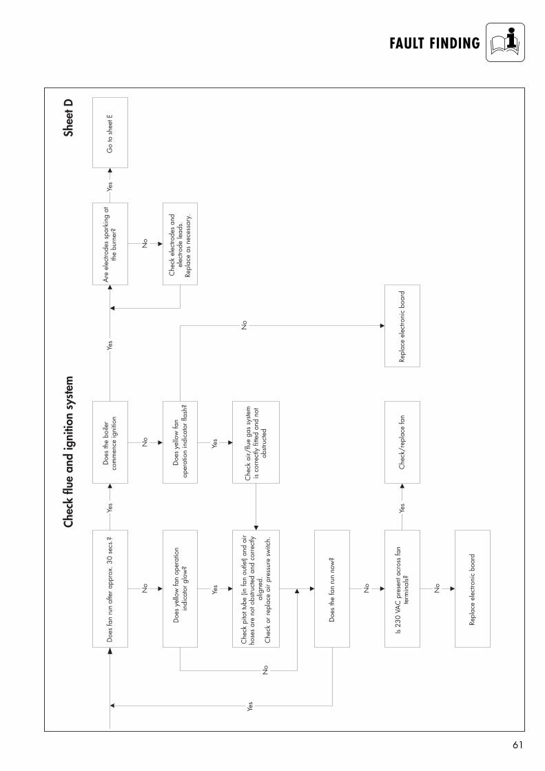
61
FAULT FINDING
Doe
s fa
n ru
n af
ter a
ppro
x. 3
0 se
cs.?
Chec
k flu
e an
d ig
nitio
n sy
stem
No
Che
ck p
itot t
ube
(in fa
n ou
tlet)
and
air
hose
s ar
e no
t obs
truct
ed a
nd c
orre
ctly
alig
ned.
Che
ck o
r rep
lace
air
pres
sure
sw
itch.
Doe
s th
e fa
n ru
n no
w?
Is 23
0 VA
C p
rese
nt a
cros
s fa
nte
rmin
als?
Repl
ace
elec
troni
c bo
ard
Yes
No
No
Yes
No
Yes
Yes
Che
ck/r
epla
ce fa
n
Doe
s th
e bo
iler
com
men
ce ig
nitio
n
Che
ck a
ir/flu
e ga
s sy
stem
is co
rrect
ly fi
tted
and
not
obstr
ucte
d
Yes
No
Repl
ace
elec
troni
c bo
ard
No
Yes
Are
ele
ctro
des
spar
king
at
the
burn
er?
Yes
Go
to s
heet
E
No
Che
ck e
lect
rode
s an
del
ectro
de le
ads.
Repl
ace
as n
eces
sary
.
Shee
t D
Doe
s ye
llow
fan
oper
atio
nin
dica
tor g
low
? D
oes
yello
w fa
nop
erat
ion
indi
cato
r fla
sh?
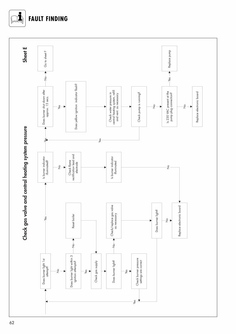
62
FAULT FINDINGCh
eck
gas
valv
e an
d ce
ntra
l hea
ting
syst
em p
ress
ure
Doe
s bu
rner
ligh
t 1st
atte
mpt
?
Doe
s bu
rner
ligh
t with
in 3
igni
tion
atte
mpt
s?
No
Yes
Che
ck g
as s
uppl
y
Doe
s bu
rner
ligh
t?
Yes
Che
ck b
urne
r pre
ssur
ese
tting
s ar
e co
rrect
Yes
No
Rese
t boi
ler
No
Che
ck/r
epla
ce g
as v
alve
as n
eces
sary
Doe
s bu
rner
ligh
t?
No
Repl
ace
elec
troni
c bo
ard
Yes
Is bu
rner
indi
cato
rill
umin
ated
?
No
Che
ck fl
ame
rect
ifica
tion
lead
and
elec
trode
Is bu
rner
indi
cato
rill
umin
ated
No
Yes
Doe
s bu
rner
shu
t dow
n af
ter
appr
ox. 1
5 se
cs.
No
Go
to s
heet
F
Yes
Che
ck w
ater
pre
ssur
e in
cent
ral h
eatin
g sy
stem
, ref
illan
d ve
nt. a
s ne
cess
ary
Che
ck p
ump
is ru
nnin
g?
Yes
Yes
Repl
ace
pum
p
No
Is 23
0 VA
C p
rese
nt a
t the
pum
p pl
ug c
onne
ctio
n?
No
Repl
ace
elec
troni
c bo
ard
Shee
t E
Doe
s ye
llow
igni
tion
indi
cato
r fla
sh?
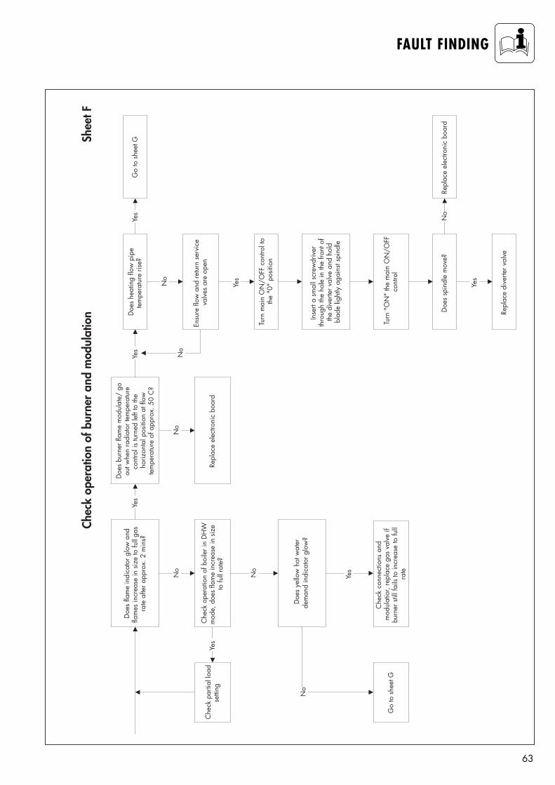
63
FAULT FINDING
Doe
s fla
me
indi
cato
r glo
w a
ndfla
mes
incr
ease
in s
ize
to fu
ll ga
sra
te a
fter a
ppro
x. 2
min
s?Ye
s
Doe
s bu
rner
flam
e m
odul
ate/
go
out w
hen
radi
ator
tem
pera
ture
cont
rol i
s tu
rned
left
to th
eho
rizon
tal p
ositi
on a
t flo
wte
mpe
ratu
re o
f app
rox.
50
C?
Yes
Doe
s he
atin
g flo
w p
ipe
tem
pera
ture
rise
?G
o to
she
et G
Yes
Chec
k op
erat
ion
of b
urne
r an
d m
odul
atio
n
Ensu
re fl
ow a
nd re
turn
ser
vice
valv
es a
re o
pen
No
No
No
Repl
ace
elec
troni
c bo
ard
No
Che
ck o
pera
tion
of b
oile
r in
DH
Wm
ode,
doe
s fla
me
incr
ease
in s
ize
to fu
ll ra
te?
Yes
Che
ck p
artia
l loa
dse
tting
No
No
Go
to s
heet
G
Yes
Che
ck c
onne
ctio
ns a
ndm
odul
atio
r, re
plac
e ga
s va
lve
ifbu
rner
stil
l fai
ls to
incr
ease
to fu
llra
te
Turn
mai
n O
N/O
FF c
ontro
l to
the
"0"
posit
ion
Yes
Inse
rt a
smal
l scr
ewdr
iver
thro
ugh
the
hole
in th
e fro
nt o
fth
e di
verte
r val
ve a
nd h
old
blad
e lig
htly
aga
inst
spin
dle
Turn
"O
N"
the
mai
n O
N/O
FFco
ntro
l
Doe
s sp
indl
e m
ove?
Yes
Repl
ace
elec
troni
c bo
ard
Repl
ace
dive
rter v
alve
No
Shee
t F
Doe
s ye
llow
hot
wat
erde
man
d in
dica
tor g
low
?
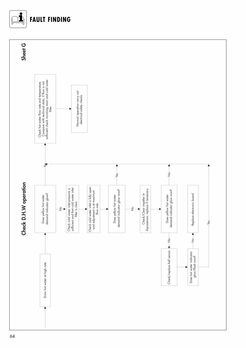
64
FAULT FINDING
Dra
w h
ot w
ater
at h
igh
rate
Yes
Che
ck h
ot w
ater
flow
rate
and
tem
pera
ture
.C
ompa
re w
ith te
chni
cal d
ata,
if fl
ow is
not
suffi
cien
t che
ck in
com
ing
mai
n an
d co
ld w
ater
filte
r.
Nor
mal
ope
ratio
n ca
rry
out
elec
trica
l saf
ety
chec
ks
No
Che
ck c
old
wat
er in
let p
ress
ure
issu
ffici
ent a
nd th
at c
old
wat
er in
let
filte
r is
clea
r
Che
ck c
old
wat
er in
let i
s fu
lly o
pen
and
adju
stmen
t is
at m
axim
umflo
w ra
te
Che
ck/C
lear
impe
ller i
nA
quas
enso
r, re
plac
e if
nece
ssar
y
Che
ck/r
epla
ce h
all s
enso
r
Repl
ace
elec
troni
c bo
ard
Doe
s ho
t wat
er in
dica
tor
glow
/fla
sh n
ow?
No
No
Yes
Yes
No
Shee
t G
No
Chec
k D.
H.W
ope
ratio
n
Doe
s ye
llow
hot
wat
erde
man
d in
dica
tor g
low
?
Doe
s ye
llow
hot
wat
erde
man
d in
dica
tor g
low
now
?
Doe
s ye
llow
hot
wat
erde
man
d in
dica
tor g
low
now
?

65
FAULT FINDING
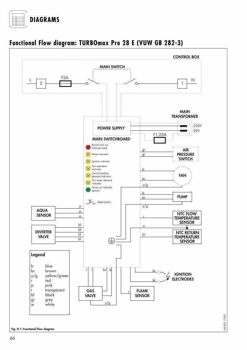
66
DIAGRAMS
POWER SUPPLY
F2AL2
N1
MAIN SWITCH
MAINTRANSFORMER
230V20V
AIRPRESSURESWITCH
FAN
PUMP
NTC FLOWTEMPERATURE
SENSOR
FLAMESENSOR
GASVALVE
AQUASENSOR
F1,25A
NTC RETURNTEMPERATURE
SENSOR
Burner lock outindicator (red)
Hot water demandindicator
Central heatingdemand indicator
Fan operationindicator
Ignition indicator
Flame indicator
Power on indicator(green)
MAIN SWITCHBOARD
IGNITIONELECTRODES
Legend
b bluebr browny/g yellow/greenr redp pinkt transparentbl blackgr greyw white
gr
b
br
y/g
bbr
y/g
br
t
w
p
t
br
br
r
bbr
y/gReset button
gr
pp
r
CONTROL BOX
DIVERTERVALVE bl
blblbl
Fig. D.1: Functional Flow diagram Euro
B/S
17
6/0
Functional Flow diagram: TURBOmax Pro 28 E (VUW GB 282-3)
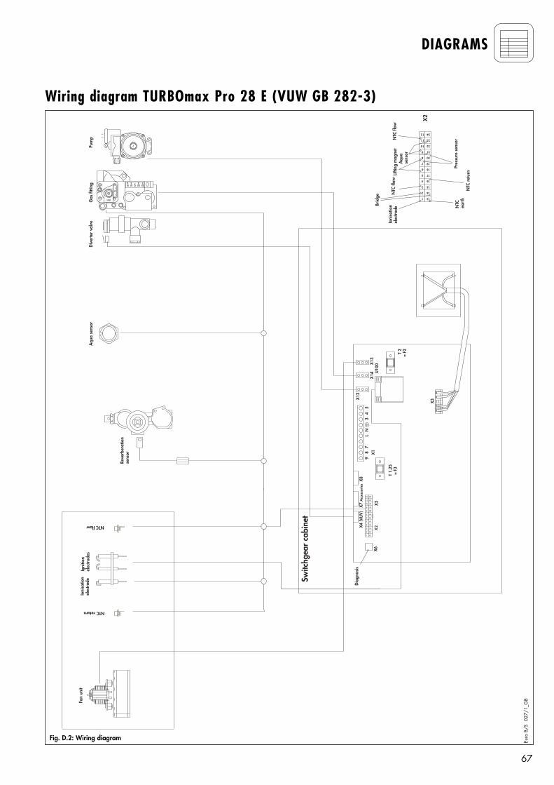
67
DIAGRAMS
Switc
hgea
r ca
bine
t
U10
0
X3
T 2
= F2
T 1,
25 =
F3
X2X2
X1
24
23
1
12
13
14
15
16
17
18
19
20
21
22
2
3
4
5
6
7
8
9
10
11
X6
Diag
nosi
s
X2
Aqu
ase
nsor
Pres
sure
sen
sor
NTC
ret
urn
NTC
ea
rth
Ioni
satio
nel
ectro
de
Brid
ge
NTC
flow
NTC
flow
Lifti
ng m
agne
t
24
23
1
12
13
14
15
16
17
18
19
20
21
22
2
3
4
5
6
7
8
9
10
11
Fan
unit
Igni
tion
elec
trode
sG
as fi
tting
Dive
rter
val
veA
qua
sens
or
Ioni
satio
nel
ectro
dePu
mp
Reve
rber
atio
nse
nsor
NTC flow
NTC return
X8X4
(VU
V)X1
2
X14
X13
97
L4
8N
35
X7 A
cces
sorie
s
1234
EV1
Fig. D.2: Wiring diagram Euro
B/S
02
7/1_
GB
Wiring diagram TURBOmax Pro 28 E (VUW GB 282-3)
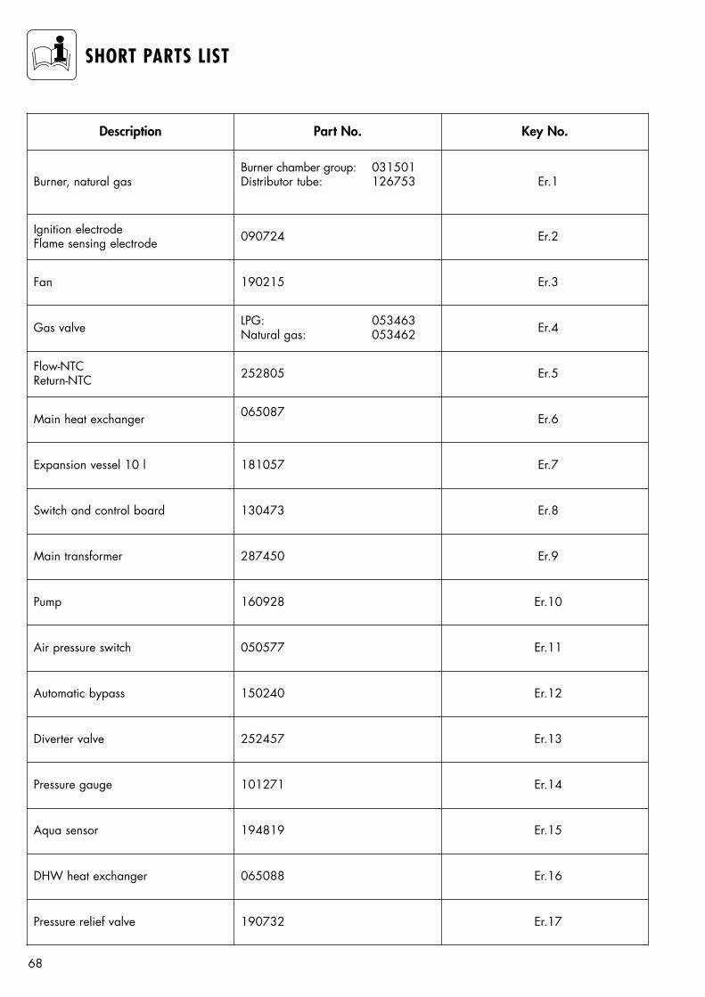
68
SHORT PARTS LIST
Description Part No. Key No.
Burner, natural gasBurner chamber group: 031501Distributor tube: 126753 Er.1
Ignition electrodeFlame sensing electrode 090724 Er.2
Fan 190215 Er.3
Gas valve LPG: 053463Natural gas: 053462 Er.4
Flow-NTCReturn-NTC 252805 Er.5
Main heat exchanger 065087 Er.6
Expansion vessel 10 l 181057 Er.7
Switch and control board 130473 Er.8
Main transformer 287450 Er.9
Pump 160928 Er.10
Air pressure switch 050577 Er.11
Automatic bypass 150240 Er.12
Diverter valve 252457 Er.13
Pressure gauge 101271 Er.14
Aqua sensor 194819 Er.15
DHW heat exchanger 065088 Er.16
Pressure relief valve 190732 Er.17
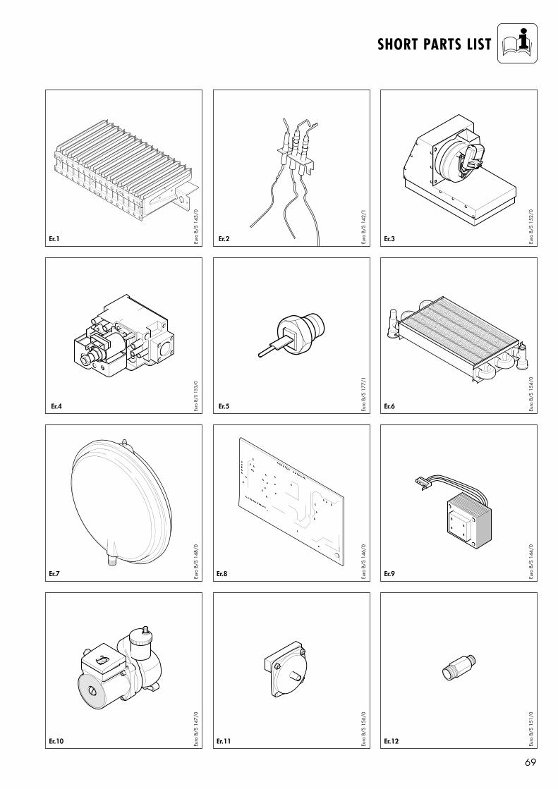
69
SHORT PARTS LIST
Er.1 Er.3
Er.4 Er.6
Er.7 Er.8 Er.9
Er.10 Er.11 Er.12
Euro
B/S
143
/0Eu
ro B
/S 1
48/0
Euro
B/S
147
/0
Euro
B/S
146
/0Eu
ro B
/S 1
56/0
Euro
B/S
152
/0Eu
ro B
/S 1
54/0
Euro
B/S
144
/0Eu
ro B
/S 1
51/0
Euro
B/S
153
/0
Er.2
Er.5
Euro
B/S
142
/1Eu
ro B
/S 1
77/1
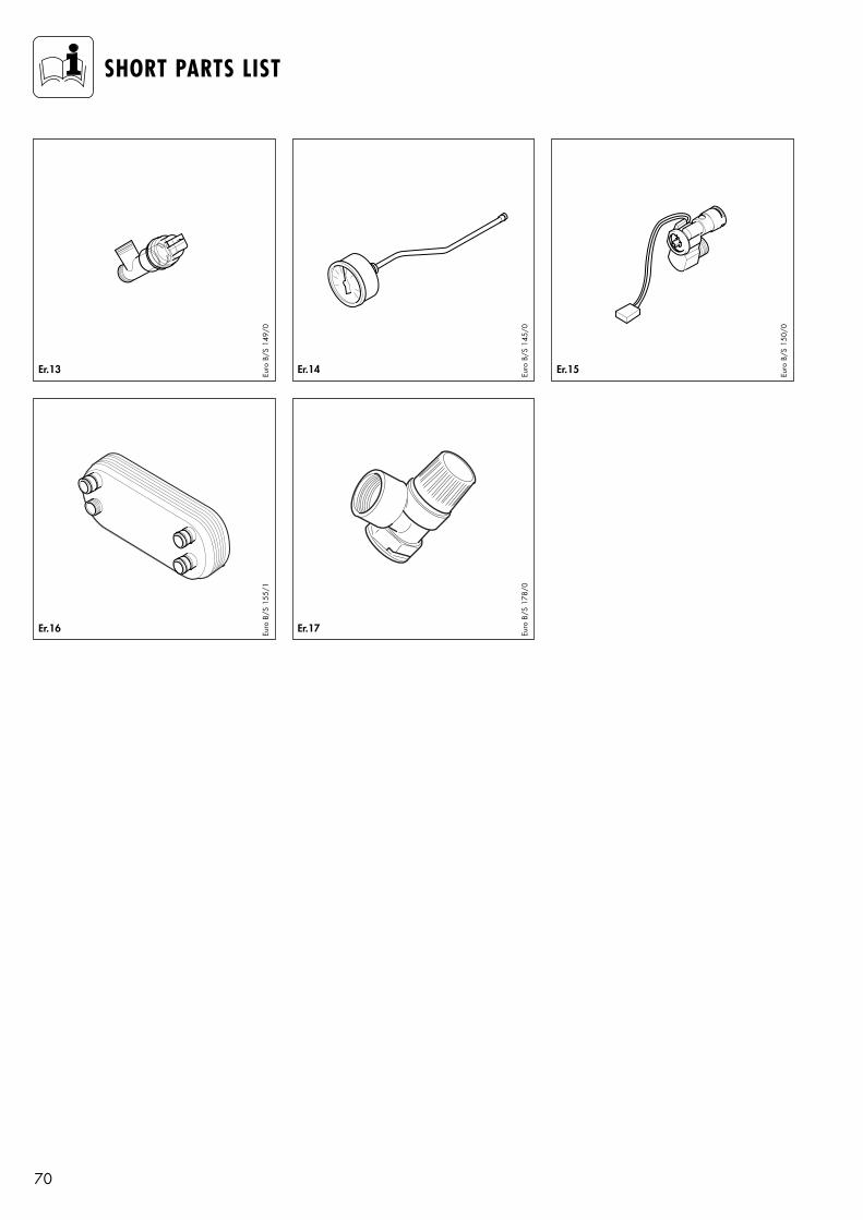
70
SHORT PARTS LIST
Er.13 Er.14
Er.17
Er.15Euro
B/S
149
/0
Euro
B/S
145
/0Eu
ro B
/S 1
78/0
Euro
B/S
150
/0
Er.16 Euro
B/S
155
/1

71

83 4
1 11
GB1
1·
02/2
002
Mü ·
Printe
d on
100
% re
cycle
d pa
per ·
Sub
ject t
o alt
eratio
n
Head OfficeVaillant Ltd., Vaillant House,Medway City Estate, Trident Close,Rochester, Kent ME2 4EZ
Service Solutions 0870 6060 777Technical Advice 01634 292392