Embed Size (px)
Citation preview
11/19
INSTRUCTIONS FOR EDITING AND COORDINATION
SECTION 08100
METAL DOORS AND FRAMES
1. New hollow metal opening construction: The minimum width of doors shall be 3'-0". Egress doors with panic hardware shall be a minimum of 3-4”. Kitchen storeroom, exterior receiving doors, walk-in cooler/refrigerator in High and Middle Schools shall be a minimum of 4’-0” in order to allow pallets thru the doors. For Elementary school 3’-0” door shall be used everywhere in the kitchen.
2. New frame openings shall be 7'-4" high at the following locations:
A. Exterior doors.
B. Corridor exit and fire doors.
C. Mechanical and Electrical rooms.
3. All exterior doors in new or existing openings shall be hollow metal.
4. All hollow metal frames shall be grouted solid.
08100-1 11/19
SECTION 08100
METAL DOORS AND FRAMES
PART 1 - GENERAL
1.01 RELATED DOCUMENTS
A. Drawings and General Provisions of Contract, including General Conditions and Division 1 Specification Sections, apply to the Work of this Section, with special attention to the following:
1. Section 01092 - Mounting Heights
1.02 RELATED WORK
A. Section 08211 - Wood Doors (Particle Core)
B. Section 08326 – Cross Corridor Packaged Door Pair Assemblies
C. Section 08710 - Finish Hardware
D. Section 08800 - Glazing (vision panels).
E. Section 09900 - Painting
F. Section 16620 - Security Intrusion
1.03 DESCRIPTION OF WORK
A. This Section includes provision and installation of exterior hollow metal doors, exterior and interior hollow metal door frames, and interior hollow metal window frames where indicated on the drawings.
1.04 QUALITY ASSURANCE
A. Hollow metal work: Manufactured in accordance with requirements of ANSI/SDI-100-91 "Recommended Specifications for Standard Steel Doors and Frames".
B. Hollow metal door and frame supplier: Direct factory supplier who employs a certified door consultant (CDC) or other individual who can demonstrate equivalent knowledge and experience.
C. Field Installation: Comply with SDI-105, "Recommended Erection Instructions for Steel Frames."
D. Labeled Fire Doors and Frames: Tested in accordance with UL-10B, ASTM E152, and NFPA 252.

METAL DOORS AND FRAMES SECTION 08100
08100-2 11/19
E. Installation of doors and hardware shall be in accordance with ANSI/DHI A115.1G-199, “Installation Guide for Doors and Hardware”.
1.05 SHOP DRAWINGS AND PRODUCT DATA
A. Submit shop drawings covering each type of frame, each type of door, frame anchorage details, and a door and frame schedule. Indicate coordination with hardware requirements. Show cutouts and hardware reinforcement where required.
B. Submit manufacturers product data technical specifications and installation instructions for each type of door.
C. Include certifications required to show compliance with this Section.
1.06 REQUIREMENTS OF REGULATORY AGENCIES
A. Where fire-rated doors and frames are indicated, provide units tested and labeled as a rated assembly and labeled by Underwriter's Laboratories, Inc., Intertek Testing Services - Warnock Hersey or other authorized labeling agency.
B. Non-sprinklered buildings: All labeled doors in rated enclosed stairways shall comply with the VUSBC for maximum temperature rise of 450oF after 30 minutes of standard fire test exposure. Such compliance shall be clearly stated on the door label.
1.07 DELIVERY, STORAGE AND HANDLING
A. Deliver, store, and handle hollow metal work in manner to prevent damage and deterioration.
1. Provide packaging such as cardboard or other containers, separators, banding, spreaders, and paper wrappings to protect hollow metal items.
B. Storage of Doors: Doors shall be stored in an upright position under cover. Place the units on at least 4” (101.6 mm) wood sills on floors in a manner that will prevent rust and damage. Do not use non-vented plastic or canvas shelters, which create humidity and promote rusting. If the corrugated wrapper on the door becomes wet, or moisture appears, remove the wrapper immediately. Provide at least a ¼” (6.35 mm) space between the doors to promote air circulation.
C. Storage of Frames: Frames shall be stored under cover on 4” (101.6 mm) wood sills on floors in a manner that will prevent rust and damage. Do not use non-vented plastic or canvas shelters, which create humidity and promote rusting. Assembled frames shall be stored in a vertical position, with no more than five
METAL DOORS AND FRAMES SECTION 08100
08100-3 11/19
units in a single stack. Provide at least a ¼” (6.35 mm) space between frames to promote air circulation.
D. Follow other special storage and handling requirements of manufacturer.
E. Protect exposed finish surfaces of pre-finished items with masking tape.
F. Inspect delivered doors and frames for damage. Minor damage may be repaired provided that the repairs are acceptable to the Owner’s Representative and Architect. Hollow metal doors and frames damaged in transit, during storage and handling, or during the construction process shall be replaced at no cost to the Owner when such items cannot be restored by field repairs.
1.08 WARRANTY
A. Provide a one (1) year warranty against defects in materials and workmanship.
PART 2 - PRODUCTS
2.01 METAL DOORS
A. Fabricate steel door units to be rigid, neat in appearance and free from defects, warp or buckle. To the fullest extent practical, fit and assemble units in manufacturer's plant. Clearly identify work that cannot be permanently factory - assembled before shipment, to assure proper assembly at project site. Comply with SDI-100 requirements as follows:
1. Exterior Doors: ANSI/SDI-100-16, Level IV, extra heavy-duty, Model 2 (MSG No. 14); fabricate from galvanized sheet steel.
B. Fabricate exposed faces and hardware reinforcements of doors from cold-rolled steel conforming to ASTM A924, A60 zinc coating (hot dipped).
C. Fabricate frames, concealed stiffeners, reinforcement, edge channels, louvers and moldings from either cold-rolled steel conforming to ASTM A366.
D. Close top and bottom edges of exterior doors as integral part of door construction or by addition of minimum 14-gage steel channels; conforming to ASTM A924, with A60 zinc coating (hot dipped). Top channels shall be flush, bottom channels shall be inverted or flush.
E. Core Materials
1. Non-rated doors: Non-toxic honeycomb or vertical steel stiffened internal reinforcing manufactured of hot rolled, pickled and oiled steel per ASTM A569.
METAL DOORS AND FRAMES SECTION 08100
08100-4 11/19
2. Fire labeled doors: Temperature rise rating mineral fiber core.
F. Exposed Fasteners: Unless otherwise indicated, provide countersunk, flat or Phillips heads for exposed screws and bolts.
G. Shop Painting:
1. Clean, treat, and paint exposed surfaces of steel doors, including galvanized surfaces (see 2.03, Finish).
2. Clean steel surfaces of mill scale, rust, oil, grease, dirt, and other foreign materials before application of paint.
3. Apply shop coat of prime paint of even consistency to provide a uniformly finished surface ready to receive finish paint.
H. Louver and Vision Panels
1. Provide factory pre-cut openings for installation of vision panels and metal louvers as indicated by door types shown on drawing.
2. Vision Panel Frames: Door manufacturer's standard steel glass molding, 18-gauge minimum.
3. Vision Panel Frames, Labeled Doors: Metal vision frames shall be Air Louvers, Inc. beveled vision lite with glass retainer, model #VLFEZ or VSIG, coordinate with glazing thickness, and be listed by Underwriter's Laboratories, Inc. and carry U. L. Label. All corners are to be mitered and flush welded. Counter-sunk flush mounting holes shall be pre-punched and plated thru-bolt fasteners provided by the factory. Vision frames shall be 18 gauge cold rolled steel, and shall be degreased and given a phosphate preparation prior to a baked silicon polyester powder coat finish.
I. Undercut non-rated doors as indicated on drawings to allow for adequate air transfer.
2.02 DOOR FRAMES
A. Fabricate frames with mitered corners, welded construction for interior and exterior applications. Knocked-down frames for field assembly shall be allowed only at retro-fitted applications as indicated on the drawings.
B. Minimum gauges: 16 gauge cold rolled steel for interior frames; 14 gauge galvanized steel with A60 zinc coating for exterior frames.
METAL DOORS AND FRAMES SECTION 08100
08100-5 11/19
C. Break-form steel sheets:
1. Provide profiles and shapes free of warp, buckles, fractures or other defects.
2. Form stops integral with frames unless otherwise shown.
D. Corners and connection shall be mitered and welded with exposed welds ground flush and smooth.
E. Frame Reinforcement: Reinforce per SDI 107.
1. Hinge reinforcement: Minimum 7 gauge.
2. Strike reinforcement: Minimum 16 gauge.
3. Closer reinforcement: Minimum 14 gauge.
4. Provide welded-in-place guards for all hardware cutouts.
F. Anchors:
1. Provide one anchor at each jamb for each 2 feet 6 inches of door height or fraction thereof.
2. Vary anchor types where required by conditions to provide positive fastening to, and compatible with adjacent construction:
a. Attachment to Masonry Construction:
(1) Galvanized(2) Adjustable, flat, corrugated or perforated “T” shaped with
leg not less than 2 inches wide by 10 inches long.
b. Attachment to Drywall Construction:
(1) Manufacturers standard compression type for Drywall type frame.
(2) Steel or Wood Stud type to accommodate frame jamb depth and face dimension.
c. Existing Masonry or Concrete
(1) 3/8 inch countersunk flat head bolt and expansion shields.(2) Locate 6 inches from top and bottom and maximum 24
inches on center.(3) Weld pipe spacers or other type of spacers, per
manufacturers standard design, in back of frame soffit.
METAL DOORS AND FRAMES SECTION 08100
08100-6 11/19
3. Weld a 16-gauge minimum metal clip angle at bottom of each jamb member for anchoring to floor, with a minimum of 2 fasteners per clip.
4. Provide "B-label" type adjustable strap anchors for labeled units.
2.03 PREPARATION FOR FINISH HARDWARE
A. Prepare frames and door to receive hardware:
1. Furnish hollow metal, manufacturer-approved hardware schedule, hardware templates and samples of physical hardware where necessary to ensure correct fitting and installation.
2. Preparation includes sinkages and cutouts for mortise and concealed hardware.
3. Prepare frames for security devices as required by Section 08710 and Division 16 Electrical Specifications. Provide cutouts and backboxes as part of the work of this section.
B. Provide reinforcements for both concealed and surface-applied hardware.
1. Drill and tap mortise reinforcements at factory, using templates.
2. Install reinforcements with concealed connections designed to develop full strength of reinforcements.
C. Provide dust boxes for the following:
1. Strike plate cutouts.
D. Prepare frames to receive inverted type door silencers; coordinate with approved hardware schedule.
2.04 FINISH
A. Welded unit frames and doors shall be leveled and ground smooth; exterior frames and doors shall be galvanized.
B. Apply mineral filler to eliminate weld scars and other blemishes.
C. All doors, frames, and other components shall be cleaned, phosphatized and finished with one coat of baked-on rust inhibiting primer complying with ANSI A224.1.
METAL DOORS AND FRAMES SECTION 08100
08100-7 11/19
1. Door and frame units shall be finished in the field in accordance with Paint Schedule in Section 09900, Painting.
PART 3 - EXECUTION
3.01 INSTALLATION OF FRAMES
A. Install frames and doors in accordance with the Steel Door Institute’s recommended erection procedures (SDI 105). Install labeled doors and frames in accordance with NFPA 80.
B. Exercise care in setting of frames to maintain scheduled dimensions, hold head level and maintain jambs plumb and square.
C. Secure anchorages and connections to adjacent construction; grout all frames solid.
D. Wherever possible, leave frame spreader bars intact until frames are set perfectly square and plumb, and anchors are securely attached.
E. Where frames are installed in existing wall construction, secure with manufacturers recommended, "retrofit" anchorage devices, or as otherwise indicated on the drawings.
F. Secure welded unit frames to structural steel framing concealed in hollow metal work, and make field splices.
G. Allow for expansion movement.
H. Fill exposed fasteners and other blemishes.
I. Where non-galvanized frames come in contact with concrete or masonry, coat frame throat with one full coat of bituminous paint.
3.02 DOOR INSTALLATION
A. Fit hollow metal doors accurately in frames, with clearances specified in SDI 105:
1. 1/8 inch between door and frame at heal and jambs.2. 1/8 inch at meeting edges of door pairs.3. 3/4 inch above finish floor at sills without threshold.4. 1/4 inch at sills with threshold.
B. Ensure that doors contact frame stops uniformly.
C. Install fire-rated doors with clearances specified in NFPA No. 80.
METAL DOORS AND FRAMES SECTION 08100
08100-8 11/19
3.03 HARDWARE INSTALLATION
A. Install hardware in accordance with Hardware Manufacturer’s written instructions and Section 08710. Drill and tap for machine screws where required; do not use self-tapping screws.
3.04 PRIME COAT TOUCH-UP
A. Immediately after erection, areas where primer coat has been damaged shall be sanded smooth and touched up with same primer as applied at shop.
B. Remove rust and apply touch-up primer as specified above.
C. Touch-up shall not be obvious and shall blend into paint finish.
3.05 ADJUSTMENT AND CLEANING
A. Remove dirt, excess sealant, mortar, glazing compounds, or other foreign material from exposed door and frame surfaces.
B. Adjust moving parts for smooth, unhindered operation.
C. Fill minor dents, holes etc. with metal filler and sand smooth and flush with adjacent surfaces. Prime and paint to match adjacent surface.
3.06 PROTECTION
A. Protect installed hollow metal work against damage or deterioration from other construction work or undue weathering. Correct any damages to hollow metal work prior to finish painting.
END OF SECTION
08211-1 11/19
SECTION 08211
WOOD DOORS
(PARTICLE CORE)
PART 1 - GENERAL
1.01 RELATED DOCUMENTS
A. Drawings and General Provisions of Contract, including General Conditions and Division 1 Specification Sections, apply to the Work of this Section.
1.02 RELATED WORK
A. Section 01740: Warranties and Bonds
B. Section 08100: Metal Doors and Frames
C. Section 08710: Finish Hardware
D. Section 08800: Glazing
E. Section 16610: Fire Detection and Alarm System (Fire rated doors)
1.03 REFERENCES
A. NFPA 80-99: “Fire Doors and Fire Windows”
B. NFPA 252-95: “Standard Methods of Fire Tests of Door Assemblies”
C. Architectural Woodwork Institute (AWI)
D. Window and Door Manufacturers Association (WDMA)
E. Intertek Testing Services - Warnock Hersey (ITS-WH)
F. ICC/ANSI A117-1-1998: “Accessible and Usable Buildings and Facilities”
G. UL 10C-98: “Positive Pressure Fire Tests of Door Assemblies”
1.04 DESCRIPTION OF WORK
A. Provide and install interior solid core doors, including fire doors, where shown and scheduled on the drawings.
1.05 QUALITY ASSURANCE

WOOD DOORS (PARTICLE CORE) SECTION 08211
08211-2 11/19
A. General: Comply with AWI Quality Standards of the Architectural Woodwork Institute (AWI Section 1300, latest edition), and WDMA 1.S.1A latest edition.
B. Fire Doors: Comply with NFPA 80 for labeled fire doors. Fire doors shall be tested in compliance with NFPA 252 or UL 10-C for positive pressure. A physical label shall be permanently affixed to the fire doors.
C. Supplier shall be a qualified direct distributor for the door manufacturer.
D. All doors furnished for this project shall be fabricated by a single manufacturer to ensure uniformity in appearance and construction.
E. In order to verify compliance with Product Standards in Part 2, Owner reserves the right to randomly select, field cut, and inspect two (2) doors delivered to the Project Site. Failure of the tested doors in meeting Product Standards may, at the discretion of the Owner, require replacement of some or all doors at no cost to the Owner.
1.06 SHOP DRAWINGS AND PRODUCT DATA
A. Product Data: Submit door manufacturer's product data, specifications and installation instructions for each type of wood door.
1. Include details of core and edge construction, trim for openings, and louvers and similar components.
2. Include finishing specifications for doors to receive factory applied shop finish.
3. Include certifications required to show compliance with specifications.
B. Shop Drawings: Submit shop drawings indicating location and size of each door, elevation of each kind of door, details of construction, location and extent of hardware blocking, fire ratings, requirements for factory sealing and other pertinent data.
C. Samples: Submit samples indicating veneer and door construction, indicating exposed edges, stile and rail construction, and core composition. Include door finish samples.
D. Submit manufacturer’s warranty statement.
1.07 REQUIREMENTS OF REGULATORY AGENCIES
A. Where fire rated doors are indicated on the drawings, provide units tested and labeled by Underwriter's Laboratories Inc., Factory Mutual, ITS-Warnock Hersey or other such testing agencies which are demonstrated to be acceptable to the local code officials.
WOOD DOORS (PARTICLE CORE) SECTION 08211
08211-3 11/19
B. Non-Sprinklered Buildings: All labeled doors in rated enclosed stairways shall comply with the VUSBC for maximum temperature rise of 450o F after 30 minutes of standard fire test exposure. Such compliance shall be clearly stated on the door label.
1.08 DELIVERY, STORAGE, AND HANDLING
A. Deliver wood doors to site only after completion of "wet" trades and after building is dry, heated and ventilated.
B. Deliver wood doors in manufacturer's original packaging, individually bagged, with manufacturer's identifying label intact. Inspect doors for damage after delivery.
C. Store wood doors in a secure dry area, safe from extreme variations in temperature and humidity, with HVAC system in operation. Acceptable humidity range shall be no less than 25%, nor greater than 55%.
D. Stack doors flat on lumber supported at ends and center. Protect top and bottom doors of stack from damage to door surface. Do not drag one door across another when stacking or unstacking.
1.09 WARRANTY
A. Warranty: Submit signed, warranty executed on manufacturer's standard form. Provide for replacing (including cost of rehanging and refinishing), at no cost to Owner, wood doors exhibiting defects in materials or workmanship, including warp and de-lamination, for lifetime of the installation of interior doors as follows:
1. Telegraphing of stile and rail through face, causing surface variation in excess of 1/100 inch in any 3-inch space.
2. Warp or twist of 1/4 inch or more in any plane of door face.
PART 2 - PRODUCTS
2.01 DOOR TYPES
A. Flush faced type interior wood doors (rated and non-rated).
2.02 DOORS
A. Flush Interior doors: PC-5 (AWI 1300-S-7), 1-3/4 inch thick, Type I (face assembly), Type II (core assembly), Class I with plain sliced, book matched, stain grade red oak face veneers; Custom Grade for face material and exposed edges.
1. Core construction: Particleboard core complying with AHSI A208.1-LD-2, bonded to stiles and rails.

WOOD DOORS (PARTICLE CORE) SECTION 08211
08211-4 11/19
2. Stiles: Minimum 1-3/8” (after trim) face thickness for vertical edges.
3. Top and Bottom Rails: Minimum 1-3/8” (after trim and standard undercut) face thickness for horizontal edges.
4. All horizontal and vertical edges shall be solid wood, one piece or laminated without voids or show-through except that Structural Composite Lumber (SCL) shall be acceptable as an alternative to solid wood.
5. Provide Bonded edge interface of stiles and rails to particleboard core per AWI 1300-S-5. Adhesive shall conform to Type I or Type II, ANSI/WDMA I.S.1-A Series. Abrasively plane and sand surfaces before veneering to avoid telegraphing of core parts through veneer face.
B. Fire-Rated Solid Core Doors: Grade, face veneers and stile and rail construction shall match non-rated flush interior doors, except as required to meet ratings indicated on drawings, and as noted below. Provide manufacturers standard mineral core construction for fire labeling required by drawings and as tested and labeled by a recognized testing agency listed in 1.07.
1. Provide minimum 5” top rail for door closer mounting.
C. Doors shall be pre-fit, beveled, and pre-machined at the factory.
D. Factory Finish: Provide door manufacturer’s factory finish, which shall meet or exceed AWI System TR-6, catalyzed polyurethane. Finish shall be clear (no stain). System shall consist of three coats of sealer, sanding, and two topcoats. Cure to produce finish complying with AWI Quality Standards, Section 1500.
1. Factory seal top and bottom rails of door.
E. CHPS Requirement for Low Emitting Materials
1. Products shall meet the VOC content requirements in the applicable category of South Coast Air Quality Management District (SCAQMD) rule 1113. Architectural coatings current edition.
2. Provide paints, coatings, adhesives and wood products that have low emission of VOC’s as approved by CHPS.
2.03 LOUVERS AND VISION PANELS
A. Provide factory pre-cut openings for installation of vision panels and metal louvers as indicated by door types shown on the drawings.

WOOD DOORS (PARTICLE CORE) SECTION 08211
08211-5 11/19
B. Vision Panel Frames, Non-labeled doors: Manufacturers standard flush wood glass lite moldings, matching door face veneer. Set and putty nail attachment locations.
C. Vision Panel Frames, Labeled Fire Doors: Metal vision frames shall be Air Louvers, Inc. or comparable beveled visionlite with glass retainer (model #VLF-EZ), listed by Underwriter's Laboratories, Inc. and shall carry U.L. label. All corners shall be mitered and flush welded. Counter-sunk flush mounting holes shall be prepunched and plated thru-bolt fasteners provided by the factory.
Vision frames shall be 18 gauge cold rolled steel, and shall be degreased and given a phosphate preparation prior to a baked silicon polyester powder coat finish.
2.04 FABRICATION
A. Fabricate doors in accordance with requirements of AWI Quality Standards, Section 1300 and WDMA standards (I.S. 1-A).
B. Provide doors with minimum 1/4 inch thick edge strips, of wood species to match face veneers.
C. Bevel-strike edge of single acting doors 1/8 inch in 2 inches. Radius strike edge of double acting swing doors 2-1/8 inches.
D. Pre-machine and prepare doors to receive hardware. Refer to Section 08710 for hardware requirements. Provide proper blocking to accommodate hardware. Comply with approved hardware schedule and hardware templates.
1. Coordinate with Division 16 for preparation required to accommodate security devices and electromagnetic door holders.
E. Where doors shall be installed in existing frames, fabricate doors to fit existing
frames. Field verify all existing frames prior to door fabrication to ensure correct fit.
PART 3 - EXECUTION
3.01 INSPECTION
A. Inspect the locations where the doors shall be installed. Notify the Architect and Owner’s Representative of any conditions that would adversely affect the installation or normal operation of the doors. Do not proceed until unsatisfactory conditions have been corrected.
1. Verify that door frames are of type required for door and are installed as required for proper installation of doors.

WOOD DOORS (PARTICLE CORE) SECTION 08211
08211-6 11/19
2. Inspect frames prior to door installation. Do not install doors in frames out of plumb or square that would otherwise hinder the proper operation of the doors.
B. Field Testing: Owner may elect to field cut two (2) doors as described in 1.05 E.
3.02 INSTALLATION
A. Fitting and Machining (for new doors in existing frames).
1. Fit doors for width by planing; for height by sawing.
a. 1/2 inch from bottom.
b. 1/8 inch maximum from top.
c. Comply with NFPA 80 for fitting clearances of fire-rated doors.
2. Machine doors for hardware. A plus or minus 1/32-inch tolerance is allowable on hardware locations. A plus 1/32-inch, minus 1/64-inch tolerance is allowable for lock front cutouts
3. Seal job site cut surfaces with two (2) coats of varnish before final hanging of doors.
B. Installation of Doors:
1. Install in accordance with requirements of AWI Section 1300 and WDMA standards. All doors shall be allowed to acclimate to controlled building environment (temperature and humidity) before installation.
2. Clearances:
a. Allow maximum of 1/8 inch at jamb and head.
b. Allow maximum of 1/8 inch at lock edges.
c. Allow maximum of 3/8 inch over threshold or saddle.
d. Allow maximum of 1/2 inch over decorative floor coverings (3/4 inch maximum for non-combustible floor).
3. Install fire-rated doors in accordance with NFPA 80.
4. Drill pilot holes for all fasteners for hinges, lock hardware, and other devices.

WOOD DOORS (PARTICLE CORE) SECTION 08211
08211-7 11/19
5. Field finishing: For field modifications only. See Section 09900, Painting. Field finishing shall be performed on all six sides of doors prior to hardware installation.
3.03 WORK AT EXISTING WOOD DOORS (delete if not applicable to project work scope)
A. Trim and refit interior non-rated doors in conjunction with new carpet work where necessary to ensure free door movement. Seal all cut edges immediately after alterations.
B. Modify exterior doors as required to receive new weatherstripping and hardware specified under Section 08710.
C. No doors bearing Labels showing compliance with U. L., Warnock-Hersey or Factory mutual fire resistance criteria shall be altered in field.
D. Work includes removal and replacement of all hardware as required to accomplish Work specified herein, and required for proper reinstallation.
3.04 ADJUSTMENT AND CLEANING
A. Wood doors that are hingebound, not swinging freely or otherwise operating improperly shall be rehung; replace door(s) if deficiencies cannot be corrected by rehanging.
B. Protect doors to minimize damage or deterioration prior to Owner acceptance. Temporarily cover doors with original wrapping until accepted.
C. Refinish or replace doors damaged during construction.
D. Remove all trash and debris associated with the work of this Section from the Project area and dispose of legally.
END OF SECTION

08326-1 11/19
SECTION 08326
CROSS CORRIDOR PACKAGED DOOR PAIR ASSEMBLIES
PART 1 - GENERAL
1.01 RELATED DOCUMENTS
A. Drawings and General Provisions of Contract, including General Conditions and Division 1 Specifications Sections, shall apply to this Section.
1.02 RELATED WORK
A. Section 08100 - Metal Doors and Frames
B. Section 08710- Finish Hardware
C. Section 09900 - Painting
D. Section 16610 - Fire Detection and Alarm System
1.03 DESCRIPTION OF WORK
A. Provide and install cross-corridor door pair assemblies, including frame, where indicated on the Drawings. Except for work excluded, assemblies shall include hardware (factory installed or provided and installed as a package under this section) and other accessories required for a complete, functioning installation, labeled where scheduled.
B. Work excluded: Provision and installation of magnetic door holders and permanent core.
1.04 SUBMITTALS
A. Shop Drawings: Indicate each door and frame condition, with applicable installation details, finish hardware, and finishes.
B. Product Data: Provide manufacturer's catalog cuts and technical data for doors, hardware and trim. Provide evidence of compliance with hourly rating as required for labeled assemblies.
C. Samples:
1. Upon request, provide physical sample of door slab showing core and face construction. Show vertical edge construction, top and bottom construction stiffeners, hinge condition and applied hardware reinforcement.
2. Provide sample of continuous hinge.

CROSS CORRIDOR PACKAGED DOOR PAIR ASSEMBLIES SECTION 08326
08326-2 11/19
3. Submit color/finish samples for hardware and trim.
1.05 QUALITY CONTROL
A. Installer qualifications: Installer of door assemblies shall be an authorized representative of the Manufacturer.
B. Installer shall employ workmen who are knowledgeable and well trained in the Manufacturer's installation procedures.
C. The Factory representative shall inspect all cross corridor door pair assemblies (see 3.04, Inspection).
1.06 DELIVERY, STORAGE, AND HANDLING
A. Deliver door assemblies to project area only after completion of "wet" trades.
B. Deliver door assemblies in Manufacturer's intact, original packaging, with all identifying labels attached.
C. Store door assemblies in an upright position in a secure, conditioned space until ready for installation. Place units on sills at least 4” high. Inspect packaging to ensure that doors are not subject to trapped moisture. Provide space between doors for air circulation.
1.07 REQUIREMENTS OF REGULATORY AGENCIES
A. Where fire-rated doors and frames are indicated on the Drawings, provide units tested and labeled by Underwriter's Laboratories, Factory Mutual, Warnock-Hersey, or other testing agency acceptable to local code officials.
B. Non-Sprinklered Buildings: All labeled doors in rated enclosed stairways shall
comply with the VUSBC for maximum temperature rise of 450F after 30 minutes of standard fire test exposure. Such compliance shall be clearly stated on the door label.
1.08 WARRANTY
A. Provide Manufacturer's standard warranty covering door assemblies against defects in materials and workmanship for a minimum period of two (2) years.
PART 2 - PRODUCTS
2.01 ACCEPTABLE DOOR SYSTEM MANUFACTURERS
A. "Total Door Systems", as manufactured by Openings, Inc. (40 West Howard Street, Pontiac, Michigan 48058, 1-248-335-7380, www.total-door.com).

CROSS CORRIDOR PACKAGED DOOR PAIR ASSEMBLIES SECTION 08326
08326-3 11/19
B. “The Rite Door”, as manufactured by Adams Rite Manufacturing Co. (260 Santa Fe Street, Pomona, CA 91767, 1-800-872-3267, www.adamsrite.com).
C. “CVC Door System”, as manufactured by Von Duprin, Div. of Ingersoll-Rand Co. (2720 Tobey Drive, Indianapolis, IN 46219, 1-317-613-8944, www.vonduprin.com)
D. Other manufacturers, when pre-bid approved in accordance with Section 01630, shall be acceptable.
2.02 MATERIALS
A. Door Assemblies: Provide doors complete with hinging and/or suspension system, locking mechanism, and hollow metal doors complying with applicable provisions of Section 08100 for hollow metal doors. Doors shall be labeled as scheduled on the Drawings.
B. Frames: Comply with applicable provisions of Section 08100 for hollow metal frames, compatible with door and hardware requirements of this Section.
C. Hardware: All hardware shall be factory installed and shall include, but not be limited to, the following:
1. Panic Exit Devices (Total Door System): Series P14, function LP05 panic exit device with 60 series lever handle and Q19 escutcheon for both leaves of pair. Provide function PEO panic exit device at double egress doors only.
2. Panic Exit Devices (Rite Door): Adams Rite Manufacturing Company. Inset Exit Device concealed Top Rod Only. Standard doors: Model D-8576 (Life Safety Rated). Fire rated doors: Model D-3676.
a. Life safety rated devices shall dog with push bar protruding no more than 3/8 inch beyond surface of door.
b. Undogged devices shall not protrude more than 1-3/8 inch beyond door surface.
c. Push bar travel shall be one inch toward mounting bar.
d. Lever: Adams Rite Model 3081, 3082, or 3083; match style of lever provided under Section 08710: Door Hardware.
3. Panic Exit Devices (“CVC” Door System): Ingersoll Rand Co., Von Duprin 9949 Series exit device, with concealed vertical cable, Less Bottom Latch (LBL) . pre-installed on Steelcraft L Series flush hollow metal doors. Standard doors Model 9949-LBL; fire rated doors: Model 9949-F-LBL.
a. Lever/Lever Trim: Von Duprin 996L / 996L-BE

CROSS CORRIDOR PACKAGED DOOR PAIR ASSEMBLIES SECTION 08326
08326-4 11/19
4. Hinges: Manufacturer’s standard, subject to compliance with the following: continuous linear hinge, painted steel, full mortise, extending full height of door. Hinges for labeled doors shall be listed by Underwriters Laboratories, Inc., for up to 90 minutes.
a. Approved manufacturer for hinges:
1) Reference 08710-Finish Hardware.
2) Pre-bid approved substitution in accordance with Section 01630.
5. Closers: Rigid, heavy duty, parallel arm with full feature metal cover.
a. Size the closers in accordance with manufacturer's recommendations. Closers shall comply with ADA Accessibility guidelines for opening force and sweep period. Closers shall have adjustable backcheck and positioning valve.
b. Install closers at 180-degree templating to provide maximum ADA opening force compliance.
c. Approved closers:
1) Reference 08710-Finish Hardware / High Frequency Surface Door Closers
6. Electro-magnetic Door Holders: Furnished and installed under Section 16610.
7. Cylinders: Furnish and install Schlage Full Size Interchangeable Core Mortise Cylinder Housing where keyed cylinders are required. Construction & Permanent Cores furnished and installed under Section 08710.
2.03 FINISHES
A. Door Faces and edges: Manufacturer's standard factory prime painting. Doors shall have final field applied painted finish in accordance with Section 09900.
B. Hardware:
1. Panic Exit Devices: US26D satin chrome
2. Lever Trim: US26D satin chrome.
3. Closers: Manufacturer's standard aluminum paint finish on metal cover.

CROSS CORRIDOR PACKAGED DOOR PAIR ASSEMBLIES SECTION 08326
08326-5 11/19
2.04 FABRICATION
A. Fabricate cross-corridor door pair assemblies in compliance with Manufacturer's written specifications and applicable code requirements.
B. Verify dimensions and field conditions prior to commencing fabrication. Notify Architect when conditions are encountered that are at variance with shop drawings.
C. Coordinate door assembly details with details of adjacent work in order to assure proper attachments and clean, neat fitting junctions.
PART 3 - EXECUTION
3.01 INSPECTION OF PREMISES
A. Prior to commencing installation of the Work, examine parts of the building structure which are to receive the door assembly. Notify the Architect and Owner’s Representative of any discrepancies or conditions that would adversely affect proper installation and performance of door system. Do not proceed until such conditions have been corrected.
3.02 INSTALLATION
A. Install Work in accordance with reviewed shop drawings, requirements of this Section, and Manufacturer's written installation instructions.
B. Hang doors and adjust to freely swing without binding, sticking, sagging, or excessive clearances. Maintain tolerances as required by Manufacturer. Install labeled doors in accordance with NFPA 80.
C. Once installation is complete, adjust operating hardware for proper operation.
3.03 PROTECTION
A. Protect installed door assemblies from damage until final acceptance by Owner. Repair damage in accordance with Manufacturer's recommendations, or replace unit at no cost to Owner if damage is the result of activities of other trades.
3.04 INSTALLATION INSPECTION
A. The Factory Representative shall inspect all installed cross corridor door pair assemblies and hardware prior to final acceptance by the Owner, in order to ensure proper installation, adjustment, and operation. The representative shall provide a written report to the Owner’s Representative and the Architect within two weeks after inspection.

CROSS CORRIDOR PACKAGED DOOR PAIR ASSEMBLIES SECTION 08326
08326-6 11/19
3.05 CLEAN UP
A. Remove all debris, tools and excess materials associated with the Work of this Section, and dispose of legally off site.
END OF SECTION

11/19
INSTRUCTIONS FOR EDITING
SECTION 08330
OVERHEAD COILING GRILLES
1. Only use overhead Coiling Grilles where possible to avoid dead-end corridors.
08330-1 11/19
SECTION 08330
OVERHEAD COILING GRILLES
PART 1 - GENERAL
1.01 RELATED DOCUMENTS
A. Drawings and General Provisions of Contract, including General Conditions and Division 1 Specification Sections, apply to the Work of this Section, with special attention to the following:
1. Shop Drawings: Section 01340.
2. Operating and Maintenance Data: Section 01730.
3. Warranties and Bonds: Section 01740.
1.02 RELATED WORK
A. Cylinder keying: Section 08710.
B. Electrical Connections (Where applicable for motorized installations): Division 16 Specifications.
1.03 DESCRIPTION OF WORK
A. Locations of overhead coiling grilles and types of installations are indicated on the Drawings.
B. Furnish and install grilles as complete, functioning assemblies.
C. Where applicable, furnish all inserts and anchoring devices required to be built into openings by work of other trades.
1.04 QUALITY ASSURANCE
A. Single Source Responsibility: Provide coiling grilles as complete assemblies produced by one manufacturer.
B. Installation shall be performed by an authorized representative, in accordance with manufacturer's standards and instructions.
1.05 SUBMITTALS
A. Product Data: Submit manufacturer's product data, rough-in diagrams and installation instructions. Provide operating and maintenance information in accordance with Section 01730.

OVERHEAD COILING GRILLES SECTION 08330
08330-2 11/19
B. Shop Drawings: Submit drawings detailing the interface of coiling grilles with each opening condition. Provide drawings of special components or special conditions that are not otherwise fully presented in product data.
1.06 WARRANTY
Provide manufacturer's standard one (1) year warranty on parts and labor.
PART 2 - PRODUCTS
2.01 ACCEPTABLE MANUFACTURERS
A. Wayne Dalton, Mt. Hope, OH, 1-800-827-DOOR, www.wayne-dalton.com (Basis of Specification).
B. Cornell Iron Works, Mountaintop, PA, 1-800-233-8366, www.cornelliron.com (subject to compliance with the requirements of this Specification)
C. Other manufacturers, pre-bid approved in accordance with Section 01630, and complying with the requirements and the intent of this Section shall be acceptable.
2.02 MATERIALS AND CONSTRUCTION
A. Grille Curtain: Straight Pattern design; Staggered Link or Brick Pattern shall not be acceptable. Curtain construction shall be as follows:
1. Continuous, roll formed 5/16" minimum diameter galvanized steel horizontal rods, covered with aluminum spacer tubes, spaced 2" maximum on center, and interconnected by aluminum vertical links. The vertical links shall be spaced no more than 6" on center, and shall rotate on the rods.
2. Bottom Bar: Manufacturer's standard extruded aluminum tube, reinforced for wider openings where required by manufacturer's standards for design.
a. Provide replaceable PVC or neoprene continuous floor bumper.
b. Where motorized grilles are indicated, provide "Sensor Edge" safety bottom bar to stop or reverse operation should grille come in contact with an obstruction.
3. End Links: Manufacturer's standard end links, designed to retain curtain in guides, and to maintain curtain alignment and prevent lateral movement.
OVERHEAD COILING GRILLES SECTION 08330
08330-3 11/19
B. Locking Device (Manual push-up): Slide bolts with cylinder locks on secured side and thumb latch with security mesh on the unsecured side. Cylinder locks shall be Schlage and shall be provided under Section 08710. Locks shall be factory installed.
C. Jamb Guides: Manufacturer's standard design; extruded aluminum with return lips of bars to retain curtain in position. Guides shall accommodate a continuous pile strip, PVC insert, or other continuous device to prevent metal-to-metal contact and minimize travel noise. See Drawings for jamb type and mounting condition.
D. Counterbalancing Mechanism: Grille shall be counter balanced by means of one or more steel helical torsion springs, mounted around a cold-rolled inner steel shaft, and contained in a spring barrel.
1. Springs shall be oil tempered, heat-treated steel, greased, packed and designed to accommodate an overload factor of 25%. Spring tension shall be adjustable, and accessible from outside of end bracket plate or barrel.
2. Counterbalance mechanism shall be designed to limit deflection to 0.03" per foot of door opening width under full loading.
3. Ball bearings shall be greased sealed or self-lubricating bearings.
4. Bracket Plates: Manufacturer's standard design, to carry counterbalancing shaft. Drive end brackets for motorized units shall have a grease sealed ball bearing.
E. Hood: Formed from 24 gauge galvanized steel when concealed, 0.032" alloy 3003 aluminum when exposed. Hood shall completely enclose coiled grille and operating mechanism. Where any portion of hood is exposed to view, provide hood with closed ends matching material and finish of hood. Concealed installation: Provide removable metal access/soffit panel and mount bottom of hood flush to the finished ceiling.
F. Operation: Provide manual push-up operation for units not exceeding 18 feet in opening width, or 11 feet in opening height.
1. Motorized Grilles: Provide motorized operation where indicated on the drawings for opening dimensions exceeding the maximum as indicated above. Motor operator shall be properly sized for weight of grille and opening width, and shall include the following features:
a. U.L. listed, with NEMA 1 enclosure, overload protection with reset, and limit switches.

OVERHEAD COILING GRILLES SECTION 08330
08330-4 11/19
b. Key controlled operation.
c. Emergency hand crank to provide operation in the event of motor failure.
G. Finish: All aluminum parts shall be mill finish. All ungalvanized ferrous metal parts shall receive a shop coat of rust inhibitive metal primer.
PART 3 - EXECUTION
3.01 INSPECTION AND INSTALLATION
A. Examine openings into which the grilles shall be installed. Notify Owner’s Representative and Architect of any adverse conditions that would affect proper installation of the Work. Do not begin until all conditions are corrected.
B. Install grilles and operating equipment complete with all necessary hardware and accessories, in accordance with approved final submittals, and manufacturer’s written installation instructions.
3.02 CLEANING AND ADJUSTMENT
A. Upon completion of the installation, lubricate, test, and adjust grilles to ensure ease of operation. Grilles shall operate free of any warpage, twisting or distortion, and fit uniformly and fully into jamb guides.
B. All exposed surfaces shall be thoroughly cleaned in accordance with manufacturer's written recommendations.
C. Remove all trash, excess materials, tools and equipment associated with the installation from the premises. Legally dispose of all trash and debris.
END OF SECTION

11/19
INSTRUCTIONS FOR EDITING
SECTION 08331
SIDE MOUNTED FOLDING GATES
1. Only use Side mounted folding gates where possible to avoid dead-end corridors.
08331-1 11/19
SECTION 08331
SIDE MOUNTED FOLDING GATES
PART 1 - GENERAL
1.01 RELATED DOCUMENTS
A. Drawings and General Provisions of Contract, including General Conditions and Division 1 Specification Sections, apply to the Work of this Section, with special attention to the following:
1. Shop Drawings: Section 01340.
2. Operating and Maintenance Data: Section 01730.
3. Warranties and Bonds: Section 01740.
1.02 RELATED WORK
A. Cylinder keying: Section 08710.
B. Electrical Connections (Where applicable for motorized installations): Division 16 Specifications.
1.03 DESCRIPTION OF WORK
A. Locations of folding gates and types of installations are indicated on the Drawings.
B. Furnish and install folding gates as complete, properly functioning assemblies.
C. Where applicable, furnish all inserts and anchoring devices required to be built into openings.
1.04 QUALITY ASSURANCE
A. Single Source Responsibility: Provide folding gates as complete assemblies produced by one manufacturer.
B. Installation shall be performed by an authorized representative, in accordance with manufacturer's written standards and instructions.
1.05 SUBMITTALS
A. Product Data: Submit manufacturer's product data, rough-in diagrams and installation instructions. Provide operating and maintenance information in accordance with Section 01730.
SIDE MOUNTED FOLDING GATES SECTION 08331
08331-2 11/19
B. Shop Drawings: Submit drawings detailing the interface of folding gates with each opening condition. Provide drawings of special components or special conditions that are not otherwise fully presented in product data.
1.06 WARRANTY
Provide manufacturer's standard one (1) year warranty on parts and labor.
PART 2 - PRODUCTS
2.01 ACCEPTABLE MANUFACTURERS
A. Acorn Wire and Iron Works, Chicago, IL, 1-800-552-2676 (www.acornwire.com) Model 5761S, Surface Mounted (Basis of Specification).
B. Criterion Products, Inc., Baldwin Park, CA, 1-888-406-1469 (www.criterionproducts.com) Model DC-3000 with JC-1000 “Quick Release” Device.
C. Other pre-bid approved manufacturers complying with the requirements and the intent of this Section shall be acceptable; see Section 01630.
2.02 MATERIALS AND CONSTRUCTION
A. Gate: Vertical members shall be two ¾” x 3/8” cold rolled channels spaced not greater than 6” o. c. Lattice bars shall be 5/8” x 3/16” cold rolled flat steel. Vertical end bars shall be cold rolled box type sections to receive roller bearings and cylinder lock. All moving parts shall be fitted with rollers. Folding type and bottom tracks shall have gusset braces in all corners. Provide automatic hold up for top track, rubber floor rests for bottom track. Gate shall have self-locking tieback arm.
B. Cabinet: Cabinet shall be constructed of 3/16” cold rolled Z bar frame with 16-gauge steel back. Flush 16 gauge door shall have formed C edges. Cabinet shall be surface mounted on wall.
C. Hinges: Gate shall have special hinges permitting cabinet door to close and lock when gate is in both stacked and extended position.
D. Locking Device: Gate shall accommodate cylinder lock on unsecured side. Provide lever handle latch with shielded enclosure on the secured side. Surface mounted cabinet shall also receive a cylinder lock. The shielded enclosure provided by the gate manufacturer shall consist of a metal case with a glass cover or “quick release” device with protective collapsible box for thumb-turn release on secured side. Cylinder locks for gate and cabinet shall be keyed alike and shall be provided under Section 08710.
SIDE MOUNTED FOLDING GATES SECTION 08331
08331-3 11/19
E. Finish: Gate and cabinet shall have electrostatic sprayed finish, color to be selected by Architect from manufacturer’s standard colors.
PART 3 - EXECUTION
3.01 INSTALLATION
A. Examine openings into which the folding gates shall be installed. Notify Owner’s Representative and Architect of any adverse conditions that would affect proper installation of the Work. Do not begin until all conditions are corrected.
B. Install folding gates and operating equipment complete with all necessary hardware and accessories, in accordance with approved final submittals and manufacturer’s written installation instructions.
3.02 CLEANING AND ADJUSTMENT
A. Upon completion of the installation, lubricate, test, and adjust grilles to ensure ease of operation. Gates shall operate free of any warpage, twisting, or distortion, and fit uniformly and fully into jamb guides.
B. All exposed surfaces shall be thoroughly cleaned in accordance with manufacturers written recommendations.
C. Remove all trash, excess materials, tools and equipment associated with the installation from the premises. Legally dispose of all trash and debris.
END OF SECTION

08332-1 11/19
SECTION 08332
OVERHEAD ROLLING SERVICE DOORS
PART 1 - GENERAL
1.01 RELATED DOCUMENTS
A. Drawings and general provisions of the Contract, including General Conditions and Division 1 specifications sections apply to this Section.
1.02 RELATED WORK
A. Cylinder Keying: Section 08710.
1.03 SUMMARY OF WORK
A. Location(s) of overhead rolling doors are indicated on the Drawings.
B. Furnish and install manual, overhead, insulated rolling doors as complete functioning assemblies.
1.04 SYSTEM DESCRIPTION
A. Design Requirements
1. Wind loading: Design and reinforce rolling doors to withstand a 20 PSF wind loading pressure.
2. Cycle life: Design doors for a “normal use” cycle of 20 cycles per day.
1.05 QUALITY ASSURANCE
A. Manufacturer’s Qualifications: ISO 9001 registered, with a minimum of five years’ experience in producing overhead rolling service doors.
B. Installer’s Qualifications: Shall have written approval by the service door manufacturer and a minimum five years’ successful experience in installing overhead rolling service doors.
1.06 SUBMITTALS
A. Comply with the applicable provisions of Section 01340.
B. Submit the following:
1. Manufacturer’s product data showing major door components and accessories, material characteristics and finishes.

OVERHEAD ROLLING SERVICE DOORS SECTION 08332
08332-2 11/19
2. Manufacturer’s technical data indicating compliance with system design requirements.
3. Evidence of quality assurance compliance.
4. Shop drawings showing interface with adjacent work and other special conditions indicated on the Drawings and not covered by standard product data.
5. Manufacturer’s written installation instructions.
1.07 DELIVERY, STORAGE AND HANDLING
A. Follow manufacturer’s written recommendations for delivery, storage and handling.
B. Door components shall be delivered to the project site with original packaging intact, including all identifying labels.
C. Store door components in a secure area safe from exposure to weather and construction activities.
1.08 WARRANTY
A. Provide one year warranty against defects in materials and workmanship.
1.09 OPERATING AND MAINTENANCE DATA
A. Provide Operating and Maintenance Manuals in accordance with Section 01730.
PART 2 - PRODUCTS
2.01 ACCEPTABLE MANUFACTURERS
A. Cornell Iron Works, Inc., Mountaintop, PA, 1-800-233-8366, www.cornelliron.com, shall be the basis of specification.
B. Overhead Door of Washington, D.C., Beltsville, MD, 1-301-937-1800 (subject to the requirements of this Section).
C. Equivalent products of other manufacturers, pre-bid approved in accordance with Section 01630, shall be acceptable.
2.02 ROLLING SERVICE DOOR
OVERHEAD ROLLING SERVICE DOORS SECTION 08332
08332-3 11/19
A. Cornell “Thermiser” Insulated Door.
B. Operation: Manual chain operation using reduction gears.
C. Mounting: Interior face-of-wall mounting on prepared door opening.
2.03 DOOR MATERIALS AND CONSTRUCTION
A. Curtain slat material: No. 6F, 24 gauge galvanized steel exterior, 24 gauge galvanized steel interior. Steel: Commercial quality with ASTM A653, Grade 40 galvanized steel zinc coating (G90).
B. Insulation: 7/8” thick foamed in place closed cell urethane foam; R-value = 6.33.
C. Curtain slat construction: Double skin, interlocking roll formed slats, 15/16” thick with riveted nylon endlocks. Provide windlocks to meet specified wind load.
D. Bottom bar: Reinforced, extruded aluminum interior face with full depth insulation. Exterior slat shall match curtain slat material.
E. Finishes:
1. Exterior slat finish: Phosphate treatment of galvanized steel, followed by a baked-on polyester powder coat (minimum 2.5 mil cured film thickness). Color: As selected by Architect from manufacturers standard color range; allow a minimum of 32 colors.
2. Interior slat finish: Phosphate treatment of galvanized steel, followed by a “light gray” baked-on polyester enamel coating (minimum 0.6 mil cured film thickness).
3. Bottom bar finish:
a. Exterior face: Match exterior curtain slats
b. Interior face: Mill finish aluminum
F. Guides:
1. Fabricate from minimum 3/16” structural steel angles. Top of inner and outer guides shall be flared outwards to form a “bellmouth” for entry of curtain slats into guides. Provide removable guide stoppers. The top 16 ½” of coil side guide angles shall be removable.
2. Guide finish: ASTM A123, Grade 85, zinc coating, hot dipped galvanized.

OVERHEAD ROLLING SERVICE DOORS SECTION 08332
08332-4 11/19
G. Counterbalance shaft assembly:
1. Barrel shall be a steel pipe, capable of supporting curtain load with a maximum deflection of 0.03 inches per foot of width.
2. Spring balance: Oil tempered, heat treated steel helical torsion spring assembly. Effort required to operate shall not exceed 25 lbs. Assembly shall be equipped with wheel for applying and adjusting spring torque.
H. Brackets:
1. Fabricate from minimum 3/16” steel plate with permanently lubricated ball or roller bearings at rotating support points. Brackets shall support counterbalance assembly and form end closures.
2. Finish: Phospate treatment followed by a “light gray” baked-on polyester powder coat, minimum 2.5 mil cured film thickness.
I. Hood:
1. 24 gauge galvanized steel with reinforced top and bottom edges and ¼” intermediate support brackets.
2. Finish: Phosphate treatment followed by “light gray” baked-on polyester enamel coating.
J. Weatherstripping:
1. Bottom bar: Replaceable, 3-point compressible vinyl gasket extending into guides.
2. Replaceable vinyl strip, sealing against fascia side of curtain.
3. Lintel Seal: Nylon brush seal filled at doorhead.
4. Hood: Neoprene/rayon baffle to resist air flow above coil.
K. Locking: Master Keyable cylinder supplied under Section 08710. Cylinder shall be operable from both sides of bottom bar.
L. Vision Panels: 10” x 1 ½” x ¾” thick, oval acrylic panes set in curtain slats with double sided foam glazing tape and fully contained. Refer to Drawings for number and placement.
M. Manual chain hoist: Provide chain hoist operator with endless steel chain, chain pocket wheel and guard, geared reduction unit, and chain keeper secured to guide.

OVERHEAD ROLLING SERVICE DOORS SECTION 08332
08332-5 11/19
PART 3 - EXECUTION
3.01 INSPECTION
A. Examine substrates of adjacent work on which rolling door assembly shall be installed. Verify that conditions are in accordance with approved shop drawings and that conditions are suitable for proper installation and operation of rolling door.
B. Notify Architect and Owner’s Representative of any unsatisfactory conditions encountered during examination. Do not proceed until corrective work has been completed.
3.02 INSTALLATION
A. Install doors complete with required accessories and operating hardware. Installation shall be in accordance with manufacturer’s written instructions and the approved final shop drawings.
B. Apply a continuous bead of sealant along both edges of each guide angle and along the perimeter of the hood assembly.
3.03 ADJUSTMENTS
A. Following completion of installation, lubricate, test and adjust doors to ensure ease of operation, free from warp, twist or distortion.
3.04 CLEANING
A. Clean surfaces soiled by work of this Section in accordance with manufacturer’s written instructions.
B. Remove all surplus materials and debris associated with the work of this Section from the project area and dispose of legally.
3.05 DEMONSTRATION
A. Demonstrate proper operation and maintenance to the Owner’s personnel.

OVERHEAD ROLLING SERVICE DOORS SECTION 08332
08332-6 11/19
END OF SECTION
08333-1 11/19
SECTION 08333
ROLLING FIRE DOORS
PART 1 - GENERAL
1.01 RELATED DOCUMENTS
A. Drawings and General Provisions of Contract, including General Conditions and Division 1 Specification Sections, apply to the work of this Section.
1.02 SUMMARY
A. Section Includes: Manual, automatic closing, overhead rolling fire doors.
B. Related Sections:
1. 06100–Rough Carpentry.
2. 08710–Finish Hardware.
3. 09910–Paint.
4. Division 16. Electrical wiring and conduit, fuses, disconnect switches, connection of operator to power supply, installation of control station and wiring, and connection to alarm systems.
C. Related Products Supplied, But Not Installed Under This Section:
1. Control Station.
2. Smoke/heat detectors.
3. Annunciator
1.03 SYSTEM DESCRIPTION
A. Performance Requirements:
1. Provide doors with Underwriters' Laboratories, Inc. label for the fire rating classification, 3/4 hr.
2. Provide doors with Underwriters' Laboratories, Inc. label for “Leakage Rated Assembly” or “S” label.
a. Comply with NFPA 105 air leakage requirements.
b. Pass UL test procedure 1784.

ROLLING FIRE DOORS SECTION 08333
08333-2 11/19
1.04 SUBMITTALS
A. Reference Section 01330–Submittal Procedures; submit the following items:
1. Product Data.
2. Shop Drawings: Include special conditions not detailed in Product Data. Show interface with adjacent work.
3. Quality Assurance/Control Submittals:
a. Provide proof of manufacturer ISO 9001:2000 registration.b. Provide proof of manufacturer and installer qualifications - see 1.4
below.c. Provide manufacturer's installation instructions.
4. Closeout Submittals:
a. Operation and Maintenance Manual.b. Certificate stating that installed materials comply with this
specification.
1.05 QUALITY ASSURANCE
A. Qualifications:
1. Manufacturer Qualifications: ISO 9001:2000 registered and a minimum of five years experience in producing fire [and smoke control] units of the type specified.
2. Installer Qualifications: Manufacturer's approval.
1.06 DELIVERY STORAGE AND HANDLING
A. Reference Section 01660–Product Storage and Handling Requirements.
B. Follow manufacturer's instructions.
1.07 WARRANTY
A. Standard Warranty: Two years from Substantial Completion
PART 2 - PRODUCTS
2.01 MANUFACTURERS
A. Manufacturer: Cornell Iron Works, Inc., Crestwood Industrial Park, Mountaintop, PA 18707. Telephone: (800) 233-8366.
ROLLING FIRE DOORS SECTION 08333
08333-3 11/19
B. Model: ERD11
C. Overhead Door Company of Washington, D.C., Beltsville, MD, (301) 937-1800 (subject to compliance with the requirements of the Specification.)
D. Other manufacturers pre-bid approved in accordance with Section 01630 and complying with the standard of quality described in this Section, shall be acceptable.
2.02 MATERIALS
A. Curtain:
1. Slats: No. 5F, flat faced 22 gauge, Grade 40 steel, ASTM A 653 galvanized steel zinc coating.
2. Bottom Bar: Two 2x2x1/8 inch (50x50x3.2 mm) structural steel angles.
3. Fabricate interlocking continuous slat sections with high strength steel endlocks secured with two ¼” (6.35 mm) rivets per UL requirements.
4. Slat Finish:
a. GalvaNex Coating System and phosphate treatment followed by baked-on polyester powder coat, color as selected by Architect from manufacturer's standard color range, minimum 32 colors; minimum 2.5 mils (0.065 mm) cured film thickness; ASTM D-3363 pencil hardness: H or better.
5. Bottom Bar Finish:
a. Steel: Phosphate treatment followed by baked-on polyester powder coat, [color as selected by Architect from manufacturer's standard color range, minimum 32 colors] [custom color as selected by Architect]; minimum 2.5 mils (0.065 mm) cured film thickness; ASTM D-3363 pencil hardness: H or better.
B. Guides: Fabricate with minimum 3/16 inch (4.76 mm) structural steel. Top of inner and outer guide angles to be flared outwards to form bellmouth for smooth entry of curtain into guides. Provide removable guide stoppers to prevent over travel of curtain and bottom bar.
Top 16 ½” (419.10 mm) of coil side guide angles to be removable for ease of curtain installation and as needed for future curtain service.
1. Finish:

ROLLING FIRE DOORS SECTION 08333
08333-4 11/19
a. Steel: ASTM A 123, Grade 85 zinc coating, hot-dip galvanized after fabrication.
C. Counterbalance Shaft Assembly:
1. Barrel: Steel pipe capable of supporting curtain load with maximum deflection of 0.03 inches per foot (2.5 mm per meter) of width.
2. Spring Balance: Oil-tempered, heat-treated steel helical torsion spring assembly designed for proper balance of door to ensure that maximum effort to operate will not exceed 25 lbs (110 N). Provide wheel for applying and adjusting spring torque.
D. Brackets: Fabricate from minimum 1/4 inch (6.35 mm) steel plate with permanently lubricated ball or roller bearings at rotating support points to support counterbalance shaft assembly and form end closures.
1. Finish:
a. Phosphate treatment followed by baked-on polyester powder coat, color as selected by Architect from manufacturer's standard color range, minimum 32 colors; minimum 2.5 mils (0.065 mm) cured film thickness; ASTM D-3363 pencil hardness: H or better.
E. Hood: 24 gauge galvanized steel with reinforced top and bottom edges. Provide minimum 1/4 inch (6.35 mm) steel intermediate support brackets as required to prevent excessive sag.
1. Finish:
a. GalvaNex Coating System to include an ASTM A 653 galvanized base coating treated with dual process rinsing agents in preparation of a chemical bonding, with baked-on polyester base coat and a baked-on polyester finish coat. Hood color to match slat color.
F. Smoke Seals:
1. Bottom Bar: Two, replaceable, UL listed, nylon pile smoke seals.
2. Guides and Head: Replaceable, UL listed, nylon pile smoke seals sealing against fascia side of curtain.
2.03 ACCESSORIES
A. Locking:
1. Master keyable cylinder operable from both sides of bottom bar.
ROLLING FIRE DOORS SECTION 08333
08333-5 11/19
2.04 OPERATION
A. Manual M100 Chain Hoist: Provide combination chain / controlled closing system operator including endless steel chain, geared reduction unit, chain keeper and a combination close operation / automatic drop test cable located at floor level. Integral to the unit is a locking mechanism to hold the door at any position of travel during normal door operation mode and a governor to control automatic closing speed.
Automatic closure shall be activated by fusible link means of a fail-safe releasing device. Doors shall maintain an average closing speed of not more than 9” (229 mm) per second during normal and automatic closing. Resetting of spring tension or mechanical dropouts shall not be required.
B. Automatic Closing and Speed Governor Mechanism:
1. M100 FireGard Chain System:
a. Activation: Melting of fusible link or use of combination close operation / automatic drop test cable located at floor level.
b. Operation: Hand chain operated for normal use. When automatic closing is activated, integral brake and chain operator shall disengage. Integral governor controls closing speed.
c. Average Closing Speed: Not more than 9 inches (229 mm) per second.
d. Reset Procedure: Resetting of spring tension or mechanical dropouts shall not be required. If tested by activating automatic drop test cable, reset by releasing drop test cable. If activated by a release device, re-insert chain end link into release device. If tested by melting / cutting of fusible link, replace fusible link.
2. Cornell SS90-B Control:a. Provide a controller to release the door at the activation of a
smoke detector or fire alarm annunciation. The controller shall be 120V and capable of up to 4 different inputs.
PART 3 - EXECUTION
3.01 EXAMINATION
A. Examine substrates upon which work will be installed and verify conditions are in accordance with approved shop drawings.
B. Coordinate with responsible entity to perform corrective work on unsatisfactory substrates.

ROLLING FIRE DOORS SECTION 08333
08333-6 11/19
C. Commencement of work by installer is acceptance of substrate.
3.02 INSTALLATION
A. General: Install door and operating equipment with necessary hardware, anchors, inserts, hangers and supports.
B. Comply with NFPA80 and NFPA 105 and follow manufacturer's installation instructions.
3.03 ADJUSTING
A. Following completion of installation, including related work by others, lubricate, test, and adjust doors for ease of operation, free from warp, twist, or distortion.
3.04 FIELD QUALITY CONTROL
A. Site Test: Test doors for normal operation and automatic closing. Coordinate with authorities having jurisdiction to witness test and sign Drop Test Form.
3.05 CLEANING
A. Clean surfaces soiled by work as recommended by manufacturer.
B. Remove surplus materials and debris from the site.
3.06 DEMONSTRATION
A. Demonstrate proper operation, testing and reset procedures to Owner's Representative.
B. Instruct Owner's Representative in maintenance procedures.
END OF SECTION

08334-1 11/19
SECTION 08334
ROLLING COUNTER DOORS
PART 1 - GENERAL
1.01 RELATED DOCUMENTS
A. Drawings and General Provisions of Contract, all of the Contract Documents, including General Conditions, and Division 1 General Requirements, apply to the work of this Section.
1.02 SUMMARY
A. The work of this Section includes two (2) rolling counter doors located in Room A103, Concessions.
B. Related Sections: Other specification sections which directly relate to the work of this Section include, but are not limited to, the following:
1. Section 08710 – Finish Hardware; key cylinders for locks.
1.03 SUBMITTALS
A. Product Data: Submit manufacturer’s product data and installation instructions for each type of rolling counter door. Include both published data and any specific data prepared for this project.
B. Shop Drawings: Submit shop drawings for approval prior to fabrication. Include detailed plans, elevations, details of framing members, required clearances, anchors, and accessories. Include relationship with adjacent materials.
1.04 QUALITY ASSURANCE
A. Manufacturer: Rolling counter doors shall be manufactured by a firm with a minimum of five years experience in the fabrication and installation of rolling counter doors. Manufacturers proposed for use, which are not named in these specifications, shall submit evidence of ability to meet performance and fabrication requirements specified, and include a list of five projects of similar design and complexity completed within the past five years.
B. Installer: Installation of rolling counter doors shall be performed by an authorized representative of the manufacturer.
C. Single-Source Responsibility: Provide doors, guides, motors, and related primary components from one manufacturer for each type of door. Provide secondary components from source acceptable to manufacturer of primary components.
ROLLING COUNTER DOORS SECTION 08334
08334-2 11/19
D. Pre-Installation Conference: Schedule and convene a pre-installation conference just prior to commencement of field operations, to establish procedures to maintain optimum working conditions and to coordinate this work with related and adjacent work.
1.05 DELIVERY, STORAGE, AND HANDLING
A. Deliver materials and products in labeled protective packages. Store and handle in strict compliance with manufacturer’s instructions and recommendations. Protect from damage form weather, excessive temperatures and construction operations.
PART 2 - PRODUCTS
2.01 ACCEPTABLE MANUFACTURERS
A. Cornell Iron Works, in Mountaintop, Pennsylvania; Telephone 800-233-8366; (design standard).
B. Overhead Door Corporation, Pennsylvania Division; Telephone 800-929-2553 or 717-248-0131.
C. Other manufacturer(s) pre-bid approved in accordance with Section 01630.
2.02 ROLLING COUNTER DOORS
A. Model ESC-10 for non-fire rated Rolling Counter Door by Cornell Iron Works. Model ERC-10 for fire rated Rolling Counter Door.
B. Curtain to consist of #1F interlocked flat-faced slats, ½” deep of 22 gauge stainless steel. Molded high-strength nylon endlocks riveted to ends of alternate slats. Bottom bar to be extruded aluminum tubular section with continuous lift handle and vinyl astragal.
C. Guides to be stainless steel formed guides, 12 gauge, equipped with polypropylene pile runners and snap-on trim to cover fasteners. Attached guides to jambs with ¼” bolts, spaced not more than 12” apart.
D. Counterbalance shaft assembly shall consist of steel pipe capable of supporting curtain load with maximum deflection of 0.03” per foot of width and helical torsion spring assembly designed for proper balance of door to insure that effort to operate door will not exceed 15 pounds. Provide wheel for applying spring torque and for future adjustment.
E. Brackets shall be reinforced steel plate to support counterbalance assembly, form end closures and provide mounting surface for securing ends of hood.
F. Hood shall be 24 gauge stainless steel. Intermediate supports shall be provided as required to prevent excessive sag.

ROLLING COUNTER DOORS SECTION 08334
08334-3 11/19
G. Operation shall be manual push-up.
H. Equip doors with latching by slide bolts suitable for use with two point dead locks with mortise cylinders operable from Cafeteria side.
I. Wall Mounting Condition: Face-of-wall mounting.
2.03 FINISHES
A. Exposed stainless steel shall be #4 finish.
PART 3 - EXECUTION
3.01 PREPARATION
A. Take field dimensions and examine conditions of substrates, supports, and other conditions under which this work is to be performed. Do not proceed with work until unsatisfactory conditions are corrected.
3.02 INSTALLATION
A. Strictly comply with manufacturer’s installation instructions and recommendations. Coordinate installation with adjacent work to ensure proper clearances and allow for maintenance.
B. Instruct Owner’s personnel in proper operating procedures and maintenance schedule.
3.03 ADJUSTING AND CLEANING
A. Test roll counter doors for proper operation and adjust as necessary to provide proper operation without binding or distortion.
B. Touch-up damaged coatings and finishes and repair minor damage in a manner acceptable to Owner’s representative and Architect. Clean exposed surfaces using non-abrasive materials and methods recommended by manufacturer of material or product being cleaned.
END OF SECTION

11/19
INSTRUCTIONS FOR EDITING AND COORDINATION
SECTION 08400
ENTRANCES AND STOREFRONTS
1. Subparagraph 2.06 (E): Make sure there are screens at cafeteria and kitchen windowsshown on drawings because of flying insects.
08400-1 11/19
SECTION 08400
ENTRANCES AND STOREFRONTS
PART 1 - GENERAL
1.01 RELATED DOCUMENTS
A. Drawings and General Provisions of Contract, including General Conditions and other Division 1 Specification Sections, apply to the Work of this Section.
1.02 RELATED WORK
A. Structural Support: Division 5
B. Finish Hardware: Section 08710
C. Glazing: Section 08800
1.03 QUALITY ASSURANCE
A. Structural Properties: Design, fabricate and install work to withstand wind loads for components and cladding as defined in the current Virginia USBC Refer to the Code Sections governing Glass and Glazing, and Structural Loads. Deflection shall not exceed 1/175 of span. Provide a safety factor of 1.65 of allowable stress.
B. Provision for Thermal Movement: Fabricate and install the entrance and storefront to provide for such expansion and/or contraction of component materials as will be caused by an ambient temperature range of 150o F. without causing harmful buckling, opening of joints, undue stresses on fasteners, or other detrimental effects.
C. Water Infiltration: There shall be no water (other than condensation) on room side of any of finally fabricated and installed members. Test for infiltration in accordance with ASTM E331, using a minimum test pressure of 8 PSF.
D. Air Infiltration: Test units in accordance with ASTM E283. Infiltration shall not exceed .06 CFM per square foot of fixed area.
1.04 SUBMITTALS
A. Shop Drawings and Manufacturer's Literature:
1. Shop Drawings:
ENTRANCES AND STOREFRONTS SECTION 08400
08400-2 11/19
a. Show construction of each component, metal thickness, installation and erection details including connections, anchorage, fastening, sealing methods and location.
b. Provide sections of typical members, dimensional elevations, frame size, spacing of anchors, and fasteners and detail of accessories.
2. Manufacturer's Recommended Maintenance Procedures.
B. Samples: Submit two (2) each of the following:
1. 12-inch extrusion or rolled section.
2. Full range of standard colors available (Refer to 2.01C).
C. Certificates: Manufacturer's certificate stating that materials meet specification requirements, including the following:
1. Air Infiltration
2. Water Infiltration
3. Code compliance for Structural Performance.
1.05 PRODUCT DELIVERY, STORAGE, AND HANDLING:
A. Inspect storefront units at time of delivery. Damaged units shall be replaced at no cost to Owner.
B. Store units in upright position off ground on dunnage.
C. Protect from weather and damage in a well ventilated, dry and secure area.
D. Store in designated areas as close as possible to point of installation.
1.06 WARRANTY
A. Provide manufacturer’s written one (1) year warranty.
PART 2 - PRODUCTS
2.01 MATERIALS
A. Aluminum: 6063-T5 or T6 alloy and temper. Framing members shall have a nominal face dimension of 2" and an overall depth of 4-1/2".

ENTRANCES AND STOREFRONTS SECTION 08400
08400-3 11/19
B. Fasteners: All exposed fasteners shall be either aluminum or stainless steel in accordance with ASTM A164. No plated steel fasteners shall be allowed.
C. Finish: All exposed surfaces shall be free of scratches or other blemishes and shall be finished using the following method:
1. Organic: Kynar-based "Duranar" or "Fluropon," complying with AA-M12-C41-R1X and AAMA 2605.
2. Color: Selection shall be made from manufacturer's standard range of colors.
2.02 ACCEPTABLE MANUFACTURERS
A. Kawneer Company, Inc., Norcross, GA, 1-770-449-5555, (www.kawneeer.com) (Basis of Specification).
B. EFCO Corporation, Monett, MO, 1-800-221-4169 (www.efcocorp.com).
C. “Amarlite”, Arch Aluminum and Glass, LLC, Tamarac, FL, 1-800-432-8132 (www.arch.amarlite.com).
D. United States Aluminum, Waxahachie, TX, 1-972-937-9651 (www.usalum.com).
E. Other manufacturers, pre-bid in accordance with Section 01630, shall be acceptable.
2.03 STOREFRONT FRAMING
A. Basis of Specification: Kawneer "TRIFAB VG (VersaGlaze) 451/451T”.
1. Types of Kawneer Aluminum Storefront Systems include:
a. Trifab® VG 451 Storefront System- 2” x 4-1/2” nominal dimension; Non-Thermal Unit
b. Trifab® VG 451T Storefront System- 2” x 4-1/2” nominal dimension; Thermal Unit
2.04 ENTRANCE DOORS
A. Basis of design: Kawneer Insulclad 560, wide stile, heavy traffic thermal entrance door.

ENTRANCES AND STOREFRONTS SECTION 08400
08400-4 11/19
2.05 HARDWARE FOR ENTRANCE DOORS
A. See Section 08710 for hardware and hardware mounting heights; provide cutouts and recesses as required by manufacturer of hardware.
B. See Division 16 for security devices.
2.06 OPERABLE VENT UNITS
A. Inswing Hopper Vents: Provide Kawneer “8225TL ISOLOCK (Thermally Broken)” Project-in hopper windows, including required hardware, trims stools, shims and anchors and perimeter sealing, meeting the requirements of AAMA Grade and Performance Rating for P-AW70.
B. Outswing Casements: Provide Kawneer “1600 GLASSvent Outswing Casement” heavy commercial windows, including required hardware items, meeting the requirements of AMMA Grade and Performance Class Rating for C-AW70 windows.
C. Hardware: Cast white bronze cam locking handles for operable units. Operating hardware shall be stainless steel 4-bar hinges.
D. Stops: Provide factory installed limit stops at operable vents to control the extension of vent so that the vent shall not project beyond the face of the wall; coordinate with details on the Drawings.
E. Screens: Provide insect screens at Cafeteria and Kitchen windows only. Provide flat type screen mounted on exterior side of frame of operating units. Extruded aluminum frames, 6063-T5 alloy and temper, joined at corners: 18 x 16 mesh aluminum screen cloth; frames finished to match aluminum windows; splines shall be extruded vinyl, removable to permit rescreening.
2.07 SUNSHADE
A. Single blade sunshade system: Kawneer “Versoleil” where indicated on the Drawings.
1. Blade shape: Airfoil.
2. Blade depth: 10-inches.
3. Blade Angle Settings: 0 degrees.
2.08 FABRICATION

ENTRANCES AND STOREFRONTS SECTION 08400
08400-5 11/19
A. Accurately fit and securely join storefront frame connections to provide tightly closed joints. Accurately make all cutouts, recesses, mortising or milling operations required for hardware and reinforce with backing plates to insure adequate strengths of connections. Reinforce division and corner members as required to adequately support doors, tempered glass and additional loads. Securely anchor vertical members to structural members. Shop fabricates extruded or formed members into complete units, in such a manner that units can be installed without removal of any part.
B. Glass framing members shall provide for flush glazing on all sides with through-sightlines, and no projecting stops to face joints. The system shall provide fully resilient settings for glass and panels by use of elastomeric gaskets on both sides of the glass. Adapters and mountings for trim moldings and face materials shall be designed so as to permit the installation of these products in regular manner, and not interfere with the normal assembly and weathering of the grid framing.
C. Sizes of components and necessary field connection and fastenings required for installation shall permit easy assembly by means of standard construction equipment and tools.
D. Welding:
1. Filler rods: AWS A.5.3.62.
2. Finish surfaces free of distortion and discoloration.
3. Remove weld spatter and welding oxide from finished surfaces.
4. Grind weld beads flush with exposed surfaces and polish to blend with adjacent finish.
E. Mechanical Assemblies:
1. Fit corner joints rigid and weathertight.
2. Conceal fasteners wherever possible.
F. Protective coatings:
1. Factory-applied.
2. Solvent-clean metal surface.
3. Apply bituminous coating compound to aluminum in contract with galvanically incompatible metal.

ENTRANCES AND STOREFRONTS SECTION 08400
08400-6 11/19
4. Apply zinc chromate primer to aluminum surfaces to be installed in contact with concrete or mortar.
G. Weatherstrip:
1. Install weatherstripping in retaining grooves designed as integral part of the doorframe and stile and mullions.
2. Weatherstripping shall be continuous at corners.
H. Finish: Refer to 2.01.
2.09 HARDWARE
A. Provided and installed under Section 08710.
2.10 GLAZING
A. Shall be as specified in Section 08800.
2.11 SEALANTS
A. Shall be as specified in Section 07900.
2.12 STOREFRONT ELEVATIONS
A. See Drawings for storefront profiles and details.
PART 3 - EXECUTION
3.01 INSPECTION
A. Storefront openings shall be checked for size, plumb, level and alignment before erection of framing. Notify Architect and Owner’s Representative of any conditions encountered that would interfere with proper installation.
B. Do not proceed with installation until unsatisfactory conditions are corrected.
3.02 INSTALLATION
A. Certified Installer: Factory trained, certified, and possessing identification as a “Certified Installer”. As an alternative, installer shall demonstrate suitably equivalent competence and experience.
B. Install work true to line, plumb, level, square, in proper planes with other work, free from sags, waves, buckles, or other objectionable defects. Adequately

ENTRANCES AND STOREFRONTS SECTION 08400
08400-7 11/19
anchor work to resist safely all stresses to which the work shall normally be subjected.
C. Builders' hardware and thresholds: Coordinate with Section 08710 for accurate fit in accordance with manufacturer's printed instructions. Doors shall operate smoothly and quietly after installation and adjustment. Door closing devices shall be adjusted immediately prior to final inspection.
D. At jambs and head of frames, fill space between back of frame and the enclosing walls solid with fiberglass, rock wool, or untarred oakum packed tight to within 3/8 in. of each face of the aluminum frame.
E. Coordinate with hardware manufacturer’s representative to provide installation inspection of closers and exit devices prior to final acceptance by Owner. A written report shall be provided to the Owner’s Representative and Architect within two weeks after inspection.
3.03 CLEANING
A. Clean aluminum surfaces with a non-toxic cleanser on all exposed surfaces, removing all mortar, paint, sealants, or other contaminants.
B. Remove all debris associated with the work of this section, and dispose of legally.
3.04 PROTECTION
A. After cleaning, protect all framing members from damage by work of other trades. Protect surface finish from scratches or other blemishes. Maintain protection until final acceptance by Owner.
END OF SECTION

11/19
INSTRUCTIONS FOR EDITING AND DRAWING COORDINATION
SECTION 08520
ALUMINUM WINDOWS
EDITING:
1. Subparagraph 1.04 (B): Delete this passage if replacement windows are not part of the work scope.
2. Subparagraph 2.01 (A) 1: Make sure there are screens at cafeteria and kitchen windows shown on drawings because of flying insects.
3. Subparagraph 2.01 (I): Delete reference to replacement trim if replacement windows are not part of the work scope.
DRAWING COORDINATION:
1. Basis of Design: Select a window manufacturer for purposes of detailing. Where replacement windows are part of work scope, show window details incorporating manufacturer's panning trim on typical sill, head, and jamb conditions for existing openings.
08520-1 11/19
SECTION 08520
ALUMINUM WINDOWS
PART 1 - GENERAL
1.01 RELATED DOCUMENTS
A. Drawings and General Provisions of Contract, including General Conditions and Division 1 Specifications Sections, apply to the work of this Section.
1.02 RELATED WORK
A. Section 01520 - Construction Aids (Temporary enclosures)
B. Section 04200- Masonry
C. Section 06100 – Rough Carpentry
D. Section 07265- Liquid Applied Air Barrier
E. Section 07900 - Sealants
F. Section 08400 - Storefront Window Framing
G. Section 08800 - Glazing
1.03 REFERENCE STANDARDS
A. Specifications for Aluminum Windows: AAMA/NWWDA 101/I.S.2-97.
B. Life Cycle Specifications and Test Methods for Architectural Grade Windows: AAMA 910.
C. Test Methods for Thermal Transmittance and Condensation Resistance: AAMA 1503.
D. Air Infiltration Test: ASTM E283
E. Water Resistance Test: ASTM E331 and ASTM E547
F. Uniform Load Deflection Test and Uniform Load Structural Test: ASTM E330.
G. Care and Handling of Architectural Aluminum: AAMA-10-97
H. Organic Coatings: AAMA 2605-02
I. Anodic Coatings: AAMA 611-98

ALUMINUM WINDOWS SECTION 08520
08520-2 11/19
1.04 WORK DESCRIPTION
A. Provide materials, labor and equipment necessary for complete, in-place and functioning thermally broken, Architectural Grade, projected aluminum windows, complete with mullions, trim, hardware and all accessories as shown on the drawings and specified in this Section.
B. Replacement Windows: In addition to the scope of work described in (A) above, provide the following:
1. Removal of existing window units to include operable sashes, mullions, glazing, hardware, or other existing construction required for installation of replacement units. Integrity of existing openings shall be maintained.
2. Replacement trim and accessories such as panning, expanders, or other installation hardware specifically required for replacement work and as required to retrofit existing openings and perimeter frames (See Drawings).
1.05 QUALITY ASSURANCE
A. Acceptable Manufacturers: Not less than five (5) years experience in manufacture of aluminum windows of type specified for project.
B. Erector Qualifications: Not less than five years successful experience in installation of aluminum windows.
C. Allowable tolerances:
1. Material tolerances:
a. Solid extrusions: Minimum nominal metal thickness as required by frame profile and AAMA rating, plus or minus 0.006 inches.
b. Hollow extrusions: Minimum nominal metal thickness as required by frame profile and AAMA rating, plus or minus 0.010 inches.
2. Size tolerances: Dimensions within plus or minus 1/16 inches.
D. Source Quality Control:
1. Window test units shall comply with requirements of AAMA/NWWDA/ CSA101/I.S2/A440-08. Conduct tests to certify compliances with the following performance requirements as specified in AAMA 101-97 and indicated below.

ALUMINUM WINDOWS SECTION 08520
08520-3 11/19
2. Uniform Load Deflection Test
a. Conduct in accordance with ASTM E330.
b. Maximum deflection of frame or sash member shall not exceed 1/175 of the span in any direction when subjected to AAMA specified test pressure, both positive and negative.
c. There shall be no damage to fasteners.
3. Uniform Load Structural Test
a. With vents closed and locked, test unit in accordance with ASTM 330 at a static air pressure difference of 97.5 PSF, both positive and negative.
b. There shall be no glass breakage, damage to fasteners, hardware, support arms, actuating mechanisms, or any other damage that would render the window inoperable.
4. Water Resistance Test:
a. At static pressure difference per ASTM E331: 15 psf.
b. No water penetration for 15 minutes when window is subject to rate of flow of 5 gallon/hour/square feet with differential pressure across window unit of 6.24 psf.
5. Air Infiltration Test:
a. With vents closed and locked, perform in accordance with ASTM E283.
b. Air infiltration shall not exceed the following valves (per foot of perimeter crack) at air pressure difference of 6.24 psf:
1) Fixed Units: .06 cubic feet pr minute (ft3/min).
2) Operable Units: .10 cubic feet per minute (ft3/min).
6. Thermal Transmittance Test:
a. With vents closed and locked, test in accordance with AAMA 1503.1.

ALUMINUM WINDOWS SECTION 08520
08520-4 11/19
b. Combined Thermal Transmittance: no more than 0.45 operable 0.38 fixed BTU/hr/ft2/degree F @ 15 mph wind velocity.
7. Condensation Resistance:
a. With vents locked and closed, test in accordance with AAMA 1503.1.
b. Resistance factor (CRF): not less than 74.
8. Life Cycle Testing: Test sample preparation, testing procedures and report content shall comply with AAMA 910.
E. Minimum wall thickness of frame extrusions: 0.125".
1.06 SUBMITTALS
A. Samples: Supply required number of each of the following:
1. Two (2) - 12 inch long extrusions.
2. One (1) - Corner assembly of window.
3. Indicate full range of standard finish colors.
B. Shop Drawings and Manufacturer's Literature:
1. Shop Drawings:
a. Show construction of all parts, metal thickness, installation and erection details including connections, anchorage, fastening sealing methods, and location. Indicate all trim accessories necessary to frame new and/or existing openings.
b. Sections of typical members, dimensioned elevations, frame sizes, spacing of anchors and fasteners and details of accessories.
2. Manufacturer's Recommended Installation and Maintenance Procedures.
C. Test reports from AAMA accredited laboratories certifying test performances as specified in 1.05, Quality Assurance, for the window type specified in this Section.
D. Certificates: Manufacturer's Notice of Product Certification stating that the tested window meets or exceeds the referenced criteria for the appropriate window type per AAMA/NWWDA 101/I.S.2/A440-08.
ALUMINUM WINDOWS SECTION 08520
08520-5 11/19
1.07 PRODUCT DELIVERY, STORAGE AND HANDLING
A. Handle and protect windows in accordance with AAMA CW-10-97.
B. Store windows in upright position off ground on dunnage.
C. Protect from water and damage.
D. Store in designated areas as close as possible to point of installation.
E. Protect window units against damage from weather, construction activities or other hazards during and after installation.
1.08 WARRANTY
A. Warranty windows and glazing against failure of materials or workmanship to include water leakage or air infiltration, deflections, faulty operation of sash, deterioration of finish or metal in excess of normal weathering and defects in hardware and weather stripping.
B. Warranty Period: Unit integrity: Minimum of 5 years; Finish: Minimum 15 year warranty covering chipping, peeling, cracking and blistering.
PART 2 - PRODUCTS
2.01 WINDOWS
A. Thermally Broken, Aluminum Projected Windows: AAMA AP-AW40 minimum with inswinging hopper vent(s), as detailed on the Drawings.
1. Provide screens at cafeteria and kitchen windows only. Refer to
Drawings for specific locations.
B. Approved Manufacturers and Window Products:
1. EFCO Corporation Series 450X Thermal AW-PG120-AP Grade Projected window. (EFCO Corporation, Monett, MO, 1-800-221-4169, www.efcocorp.com.
2. Wausau Invent 4250i series project-in/ Fixed aluminum windows. Wausau, WI. 1-877-678-2983. (www.wausauwindow.com).

ALUMINUM WINDOWS SECTION 08520
08520-6 11/19
3. YKK AP America, Inc. Yow 350 T-U AW80 Thermal Project-in/Fixed Window with 1” trim. (YKK AP America, Inc., Austell, GA, 1-800-955-9551, www.ykkap.com).
4. Win-Vent Series 850 Thermal, (Win-Vent Architectural Windows, a Division of Extrusions, Inc., Fort Scott, KA, 1-800-295-3113, www.winventwindows.com).
5. Kawneer Series 6500 Thermal Project-in/ Fixed, Kawneer Company, Inc., Atlanta, GA, 1-877-505-3771 (www.kawneer.com)
6. DeSCo Series I85+ AW80 Thermal Project-in/ Fixed (DeSCo Architectural, Inc, 716 3rd St, SE DeSmet, SD 57231, 1-800-952-5534. (www.descoarc.com)
7. Pre-bid approved manufacturer and window product in accordance with Section 01630.
C. Aluminum: Extruded, 6063-T5 or T6 alloy and tempered.
D. Thermal Break Construction: Window units fabricated with an integrally concealed thermal barrier, located in a manner which eliminates metal to metal contact, and provides a continuous break around the entire perimeter of frame and sash. Reinforcing members and fasteners shall comply with Section 1 of AAMA 101-97.
E. Provide heavy duty locking cam type window hardware made of Nickel - Bronze Alloy with US25D finish for operable units. Operating hardware shall be 4-bar stainless steel arms.
F. Finish: All exposed surfaces shall be free of scratches and other blemishes and shall be finished using the following method.
1 . Organic Coating: 70% fluoropolymer paint finish complying with AAMA 2605 and AA-M12-C42-R1X.
G. Provide flat type screen mounted on exterior side of frame of operating units. Screen frame shall be extruded aluminum, tubular construction designed to interlock into frame and be removable.
H. Provide means of drainage for water and condensation by use of weep holes.
I. Replacement Trim:
1. Casing covers, panning trim: one piece, aluminum extrusions designed to lock around entire frame, to provide weathertight connection, but
ALUMINUM WINDOWS SECTION 08520
08520-7 11/19
allowing expansion and contraction. Thickness: no less than .062 inches.
2. Interior trim: Extruded aluminum, not less than .062 inches thick, with no exposed screws.
J. Stops: Provide factory installed limit stops at operable vents to control the extension of vent so that the vent shall not project beyond the face of the wall; coordinate with details on the Drawings.
PART 3 - EXECUTION
3.01 INSPECTION
A. Verify that openings are dimensionally within allowable tolerances, are plumb, level, clean, provide a solid anchoring service, and are in accordance with the Drawings and approved final shop drawings.
B. Notify the Architect and Owner’s Representative of any deficiencies or deviations from the Drawings that would impede the proper installation and operation of window assemblies. Do not proceed until such conditions have been corrected.
3.02 INSTALLATION
A. Use only skilled tradesmen, with work done in accordance with manufacturer’s written instructions and the approved shop drawings.
B. Plumb and align window faces in a single plane for each wall plane; erect windows and accessories square and true.
C. Anchor windows to maintain permanent positions when subjected to normal thermal movement, building movement and design wind load.
D. Furnish and apply sealants to provide a weather tight installation at all joints and intersections, and at opening perimeter. Wedge compressible insulation between unit frames and existing or new construction; wipe off excess sealant and leave all exposed surfaces and joints clean and smooth.
E. Cover all openings at the end of the working day, where work has not been completed, to minimize exposure to weather, and to prevent unauthorized entry into premises.
1. Secure exposed openings with plywood panels. Use of plastic sheeting is not acceptable.

ALUMINUM WINDOWS SECTION 08520
08520-8 11/19
2. Unsealed perimeter frames shall be protected temporarily by using backing rods or similar accessories.
3.03 ADJUSTMENTS
A. Adjust operating vents and hardware for tight fit at contact points and weather stripping, to ensure smooth operation of operable vents, and to provide weathertight seal.
3.04 CLEAN-UP
A. Leave windows and adjacent surfaces clean and free of excess sealant, foreign materials and other debris. Use only those cleaning agents that are recommended by window manufacturer.
B. Remove all debris, packaging, banding, and surplus materials from the job site and dispose of legally.
END OF SECTION

11/19
INSTRUCTIONS FOR EDITING
TUBULAR SKYLIGHTS
SECTION 08625
TUBULAR SKYLIGHTS
1. Page 08625-5, paragraph 2.02 (B.2, B.3, B.4, B.8): Edit items for project requirements.
2. Page 08625-6, paragraph 2.02 (B.8.b and B.8.c): Select one lens paragraph and delete the one not required for project requirements.
08625-1 11/19
SECTION 08625
TUBULAR SKYLIGHTS
PART 1 - GENERAL
1.01 RELATED DOCUMENTS
A. Drawings and General Provisions of Contract, including General Conditions and Division-1 Specification Sections, apply to the Work of this Section.
1.02 DESCRIPTION OF WORK
A. Tubular daylighting device, consisting of roof dome, reflective tube, and diffuser assembly; configuration as indicated on the drawings.
B. Accessories
1. Daylight Dimmers
1.03 RELATED SECTIONS
A. Section 07510-4 Ply Built-Up Roofing with Gravel Ballast and Insulation.
B. Section 07600-Flashing and Sheet Metal.
C. Section 16620-Security Intrusion System
1.04 REFERENCES
A. ASTM B 209- Standard Specification for Aluminum and Aluminum-Alloy Sheet and Plate.
B. ASTM E 84- Standard Test Method for Surface Burning Characteristics of Building Materials; 2008a.
C. ASTM A 463/A 463M-Standard Specification for Steel Sheet, Aluminum Coated, by the Hot Dip Process; 2006.
D. ASTM A 653/A 653M-Standard Specification for Steel Sheet, Zinc Coated (Galvanized), by the Hot Dip Process; 2007
E. ASTM A792/A 792M-Standard Specification for Steel Sheet, 55% Aluminum-Zinc Alloy Coated by the Hot-Dip Process
F. ASTM E 283-Test Method for Rate of Air Leakage Through Exterior Windows, Curtain Walls, and Doors Under Specified Pressure Differences Across the Specimen; 2004.

TUBULAR SKYLIGHTS SECTION 08625
08625-2 11/19
G. ASTM E 308-Standard Practice for Computing the Colors of Objects by Using the CIE System; 2006.
H. ASTM E 330-Structural Performance of Exterior Windows, Curtain Walls and Doors; 2002.
I. ASTM E 547-Test Method for Water Penetration of Exterior Windows, Skylights, Doors and Curtain walls by Cyclic Air Pressure Difference; 2000.
J. ASTM E 1886-Standard Test Method for Performance of Exterior Windows, Curtain Walls, Doors, and Impact Protective Systems Impacted by Missiles(s) and Exposed to Cyclic Pressure Differentials.
K. ASTM E 1996-Standard Specification for Performance of Exterior Windows, Curtain Walls, Doors and Impact Protective Systems Impacted by Windborne Debris in Hurricane.
L. ASTM D 635-Test Method for Rate of Burning and/or Extent of Time of Burning of Self-Supporting Plastics in a Horizontal Position; 2006.
M. ASTM D-1929-Test Method for Ignition Properties of Plastics; 1996 (2001).
N. UL 181-Factory Made Air Ducts and Air Connectors
O. ICC AC-16-Acceptance Criteria for Plastic Skylights, 2008.
1.05 PERFORMANCE REQUIREMENTS
A. Completed tubular daylighting device assemblies shall be capable of meeting the following performance requirements:
1. Air infiltration Test: Air infiltration will not exceed 0.30 cfm/sf aperture with a pressure delta of 1.57 psf across the tube when tested in accordance with ASTM E 283.
2. Water Resistance Test: No uncontrolled water leakage at 10.5 psf pressure differential with water rate of 5 gallons/hour/sf when tested in accordance with ASTM E 547.
3. Uniform Load Test:
a. No breakage, permanent damage to fasteners, hardware parts, or damage to make daylighting system inoperable or cause excessive permanent deflection of any section when tested at a Positive Load of 150 psf (7.81 kPa) or Negative Load of 70 psf (3.35 kPa).
TUBULAR SKYLIGHTS SECTION 08625
08625-3 11/19
b. All units shall be tested with a safety factor of (3) for positive pressure and (2) for negative pressure, acting normal to plane of roof in accordance with ASTM E 330.
4. Fire Testing:
a. When used with the Dome Edge Protection Band, all domes meet fire rating requirements as described in the 2006 International Building Code.
b. Self-Ignition Temperature-Greater than 650 degrees F per ASTM D-1929.
c. Smoke Density-Rating no greater than 450 per ASTM Standard E 84 in way intended for use. Classification C.
d. Rate of Burn and/or Extent-Maximum Burning Rate: 2.5 inches/min (62mm/min) Classification CC-2 per ASTM D 635.
e. Rate of Burn and/or Extent-Maximum Burn Extent: 1 inch (25 mm) Classification CC-1 per ASTM D 635.
1.06 SUBMITTALS
A. Submit under provisions of Section 01340.
B. Product Data: Manufacturer’s data sheets on each product to be used, including:
1. Preparation instructions and recommendations.
2. Storage and handling requirements and recommendations.
3. Installation methods.
C. Shop drawings. Submit shop drawings showing layout, profiles and product components, including anchorage, flashings and accessories.
D. Verification Samples: As requested by Architect.
E. Test Reports: Independent testing agency or evaluation service reports verifying compliance with specified performance requirements.
1.07 QUALITY ASSURANCE

TUBULAR SKYLIGHTS SECTION 08625
08625-4 11/19
A. Manufacturer Qualifications: Engaged in manufacture of tubular daylighting devices for minimum 15 years.
1.08 DELIVERY, STORAGE, AND HANDLING
A. Store products in manufacturer’s unopened packaging until ready for installation.
B. Store and dispose of solvent-based materials, and materials used with solvent-based materials, in accordance with requirements of local authorities having jurisdiction.
1.09 PROJECT CONDITIONS
A. Maintain environmental conditions (temperature, humidity, and ventilation) within limits recommended by manufacturer for optimum results. Do not install products under environmental conditions outside manufacturer’s absolute limits.
1.10 WARRANTY
A. Daylighting Device: Manufacturer’s standard warranty for 10 years.
B. Electrical Parts: Manufacturer’s standard warranty for 5 years, unless otherwise indicated.
PART 2 - PRODUCTS
2.01 MANUFACTURERS
A. Acceptable Manufacturer: Solatube International Inc; 2210 Oak Ridge Way, Vista CA 92081. 410-995-6400. Local email: [email protected]
B. Substitutions: Other manufacturers, pre-bid approved per Section 01630, shall be acceptable, provided they comply with all requirements of this section.
C. Requests for substitutions will be considered provided a lighting layout with photometric data is supplied to demonstrate light levels will meet original design intent.
2.02 TUBULAR DAYLIGHTING DEVICES
A. Tubular Daylighting Devices General: Transparent roof-mounted skylight dome and self-flashing curb, reflective tube, and ceiling level diffuser assembly, transferring sunlight to interior spaces; complying with ICC AC-16.
B. SolaMaster Series: Solatube Model 750 DS-C Penetrating Ceiling, 21 inch (530 mm) Daylighting System:

TUBULAR SKYLIGHTS SECTION 08625
08625-5 11/19
1. Roof Dome Assembly: Transparent, UV and impact resistant dome with lashing base supporting dome and top of tube.
a. Outer Dome Glazing: Type DA, 0.125 inch (3.2 mm) minimum thickness injection molded acrylic classified as CC2 material; UV inhibiting (100 percent UV C, 100 percent UV B and 98.5 percent UV A), impact modified acrylic blend.
b. Raybender 300: Variable prism optic molded into outer dome to capture low angle sunlight and limit high angle sunlight.
c. Inner Dome Glazing: Type DAI, 0.115 inch (3 mm) minimum thickness acrylic classified as CC2 material.
2. Roof Flashing Base:
a. One Piece: One piece, seamless, leak-proof flashing functioning as base support for dome and top of tube. Sheet steel, corrosion resistant conforming to ASTM A 653/A 653M or ASTM A 463/A 463M or AST A792/A 792 M, 0.028 inch (0.7 mm) plus or minus .006 inch (.15 mm) thick.
1) Base style: Type FC, Curb cap, with inside dimensions of 27 inches by 27 inches (685 mm x 685 mm) to cover curb as specified in Section 07600.
3. Curb Insulator: Type CI, Thermal isolation material for use at curb base.
4. Dome Edge Protection Band: Type PB, For fire rated roofs with turret height less than 8 inches (203 mm). Galvanized steel. Nominal thickness of 0.03i9 inch (1 mm).
5. Tube Ring: Attached to top of base section; 0.090 inch (2.3 mm) nominal thickness injection molded high impact PVC; to prevent thermal bridging between base flashing and tubing and channel condensed moisture out of tubing.
6. Dome Seal: Adhesive backed weatherstrip 0.63 inch (16 mm) tall by 0.28 inch (7 mm).
7. Reflective Tubes: Aluminum sheet, thickness 0.018 inch (0.5 mm).
a. General:
1) Interior Finish: Spectralight Infitity high reflectance specular finish on exposed reflective surface. Specular reflectance for visible spectrum (400 nm to 760 nm)

TUBULAR SKYLIGHTS SECTION 08625
08625-6 11/19
greater than 99 percent. Total solar spectrum reflectance (400 nm to 2500 nm) less than 80.2 percent.
2) Color: a* and b* (defined by CIE L*a*b* color model) shall not exceed plus 2 or be less than minus 2 as determined in accordance to ASTM E 308.
b. Top Tube Angle Adapter and Bottom Tube Angle Adapter Kit, Type AK:
1) Reflective 45 degree adjustable top and bottom angle adapters (one each), 16 inches (406 mm) long
c. Extension Tube:
1) Reflective extension tube, Type EXX, Notched for Open Ceiling diffuser attachment, 24 inches (610 mm) or 48 inches (1220 mm) long. Provide enough tubing to cover the distance from roof curb to ceiling.
8. Diffuser Assemblies for Tubes Penetrating Ceilings: Solatube Model 750 DS-C. Ceiling mounted box transitioning from round tube to square ceiling assembly, supporting light transmitting surface at bottom termination of tube, 23.8 inches by 23.8 inches (605 mm by 605 mm) square frame to fit standard suspended ceiling grids or hard ceilings.
a. Round to square transition box made of opaque polymeric material, classified as CC2, Class C, 0.110 inch (2.8 mm) thick.
b. Lens: Type L1 OptiView Fresnel lens design to maximize light output and diffusion with extruded aluminum frame and EPDM foam seal to minimize condensation and bug, dirt and air infiltration per ASTM E 283. Visible Light Transmission shall be greater than 90 percent at 0.022 inch (0.6 mm) thick. Classified as CC2.
c. Natural Effect Lens made of acrylic, classified as CC2, Class C, 0.060 inch (1.5 mm) thick, with open cell foam seal to minimize condensation and bug, dirt, and air infiltration per ASTM E 283.
9. Accessories:
a. Security Bar: Type B Security Bar 0.375 inch (95 mm) stainless steel bar across flashing diameter opening.

TUBULAR SKYLIGHTS SECTION 08625
08625-7 11/19
b. Local Dimmer Control utilizing a butterfly baffle design of Spectralight infinity reflective material to minimize shadowing when in use: Provided with dimmer switch and cable.
1) Daylight Dimmer: Type D1 Electro-mechanically actuated daylight valve; for universal input voltages ranging between 90 and 277 V at 50 or 60 Hz; maximum current draw of 50 ma per unit; controlled by low voltage, series Type T02; circuited, 4 conductor, size 22 cable; providing daylight output between 2 and 100 percent. Provided with dimmer switch and cable.
2) Switch: See division 16 and electrical drawings.
3) Cable: See division 16 and electrical drawings.
c. Security Kit: Type SK Dome Security Kit, rivets with nylon spacers to replace dome screws.
2.03 ACCESSORIES
A. Fasteners: Same material as metals being fastened, non-magnetic steel, non-corrosive metal of type recommended by manufacturer, or injection molded nylon.
B. Suspension Wire: Steel, annealed, galvanized finish, size and type for application and ceiling system requirement.
C. Sealant: Polyurethane or copolymer based elastometric sealant as provided or recommended by manufacturer.
D. Plenum Wrap: Equal to 3M Fire Barrier Plenum Wrap 5A.
PART 3 - EXECUTION
3.01 EXAMINATION
A. Do not begin installation until substrates have been properly prepared.
B. If substrate preparation is the responsibility of another installer, notify Architect of unsatisfactory preparation before proceeding.
3.02 PREPARATION
A. Clean surfaces thoroughly prior to installation.
TUBULAR SKYLIGHTS SECTION 08625
08625-8 11/19
B. Prepare surfaces using the methods recommended by the manufacturer for achieving the best result for the substrate under the project conditions.
3.03 INSTALLATION
A. Install in accordance with manufacturer’s printed instructions.
B. Install low voltage wiring in accordance with wiring installation requirements in Division 16, Section 16620.
C. After installation of first unit, field test to determine adequacy of installation. Conduct water test in presence of Owner, Architect, or Contractor, or their designated representative. Correct if needed before proceeding with installation of subsequent units.
3.04 PROTECTION
A. Protect installed products until completion of project.
B. Touch-up, repair or replace damaged products before Substantial Completion.
END OF SECTION
11/19
INSTRUCTIONS FOR EDITING
SECTION 08630
TUBULAR DAYLIGHTING DEVICE
1. Use this device only in large gymnasium spaces or other large room areas as approved in advance by owner.
2. Edit paragraph 2.02 B.5 if rated roof assemblies are not required.

08630-1 11/19
SECTION 08630
TUBULAR DAYLIGHTING DEVICE
PART 1 - GENERAL
1.01 RELATED DOCUMENTS
A. Drawings and General Provisions of Contract, including General Conditions and other Division 1 Specification Sections, apply to the Work of this Section.
1.02 RELATED WORK
A. Tubular daylighting device, consisting of roof dome, reflective tube, and diffuser assembly; configuration as indicated on the drawings.
B. Accessories
1. Daylight Dimmers2. Security Guard3. Wire Suspension Kit
1.03 RELATED SECTIONS
A. Section 07510- 4 Ply Built Up Roofing with Gravel Ballast and Insulation.
B. Section 07600- Flashing and Sheet Metal
C. Section 16110-Conduits, Raceways, Fittings and Cable Trays
1.04 REFERENCES
A. ASTM B 209 - Standard Specification for Aluminum and Aluminum-Alloy Sheet and Plate.
B. ASTM E 84 - Standard Test Method for Surface Burning Characteristics ofBuilding Materials; 2008a.
C. ASTM A 463/A 463M-Standard Specification for Steel Sheet, Aluminum Coated, by the Hot Dip Process; 2006.
D. ASTM A 653/A 653M-Standard Specification for Steel Sheet, Zinc Coated(Galvanized), by the Hot Dip Process; 2007
E. ASTM A792/A 792M-Standard Specification for Steel Sheet, 55% Aluminum-ZincAlloy Coated by the Hot-Dip Process
TUBULAR DAYLIGHTING DEVICE SECTION 08630
08630-2 11/19
F. ASTM E 283-Test Method for Rate of Air Leakage Through Exterior Windows, Curtain Walls, and Doors Under Specified Pressure Differences Across the Specimen; 2004.
G. ASTM E 308-Standard Practice for Computing the Colors of Objects by Using the CIE System; 2006.
H. ASTM E 330-Structural Performance of Exterior Windows, Curtain Walls andDoors; 2002.
I. ASTM E 547-Test Method for Water Penetration of Exterior Windows, Skylights, Doors and Curtain walls by Cyclic Air Pressure Difference; 2000.
J. ASTM E 1886-Standard Test Method for Performance of Exterior Windows, Curtain Walls, Doors, and Impact Protective Systems Impacted by Missiles(s) and Exposed to Cyclic Pressure Differentials
K. ASTM E 1996-Standard Specification for Performance of Exterior Windows, Curtain Walls, Doors and Impact Protective Systems Impacted by Windborne Debris in Hurricane
L. ASTM D 635-Test Method for Rate of Burning and/or Extent of Time of Burning of Self-Supporting Plastics in a Horizontal Position; 2006.
M. ASTM D-1929-Test Method for Ignition Properties of Plastics; 1996 (2001).
N. UL 181-Factory Made Air Ducts and Air Connectors
O. ICC AC-16-Acceptance Criteria for Plastic Skylights, 2008.
1.05 PERFORMANCE REQUIREMENTS
A. Completed tubular daylighting device assemblies shall be capable f meeting the following performance requirements:
1. Air Infiltration Test:
a. Single Dome (M74 OS Type DP): Passes Air infiltration; maximum
of 0.05 cfm/ft2 (0.3 L/s/m2) when tested according to AMAIWDMA/CSA 101/I.S.2/A440-11, ICC-ES AC-16, and ASTM E 283.
b. Single Dome (M74 OS Type DP): meets or exceeds the air leakage performance levels with a maximum 0.4 cfm/ft2 when tested in accordance with AAMAIWDMA/CSA 101/I.S.2/A440 and ASTM E 283.
TUBULAR DAYLIGHTING DEVICE SECTION 08630
08630-3 11/19
c. Air exfiltration will not exceed 0.4 cfm/sf aperture with a pressure delta of 1.57 psf across the tube when tested in accordance with ASTM E 283.
2. Water Resistance Test:
a. Single Dome (M74 OS Type DP): No uncontrolled water leakage with a pressure differential of 12.11 psf (580 Pa) or 15 percent of design pressure and a water spray rate of 5 gallons/hour/sf for 24 minutes when tested in accordance with AAMA/WDMA/CSA 101/I.S.2/A440-11, ICC-ES AC-16, ASTM E 547, ASTM E 331, and TAS 202.
3. Uniform Load Test:
a. Design Pressure ±80.20 psf (±3.84 kPa). No breakage, permanent damage to fasteners, hardware parts, or damage to make daylighting system inoperable or cause excessive permanent deflection of any section when tested at a Positive Load of 240.6 psf (11.52 kPa) or Negative Load of 160 psf (7.66 kPa) when tested according to AAMA/WDMA/CSA 101/I.S.2/A440-11, ICC-ES AC-16, and ASTM E 330
4. Hurricane Resistance:
a. Large Missile Impact test: A minimum of missile level D for Wind Zone 4. No signs of penetration, rupture, or opening when tested in accordance with ASTM E 1886 and ASTM E 1996. No signs of penetration, rupture, or opening when tested in accordance with TAS 201Uniform Static Air Pressure Test: Design pressure rating a minimum of plus or minus 80.2 psf (3.84 kPa) when tested in accordance with ASTM E 1886, ASTM E 1996, and TAS 202
5. Fall Protection Performance:
a. Passes fall protection test: (M74 OS - All Types) No penetration of dome or curb cap shall occur when subject to 700 Lb (318.2 Kg)/60 second static load test and 700 Lb (318.2 Kg)/2-foot (610 mm) impact drop test when tested in accordance with OSHA 29 CFR 1926 Subpart M (Fall Protection) 1926.501(b)(4)(i); 1926.501(i)(2); and 1926.501(b) (4)(ii).
b. Static test performed to demonstrate that a M74 OS tubular daylight device system, installed according to the manufacturer's instructions and in new or undamaged condition can support a 350-Lb (159 Kg) weight at any one time based on
TUBULAR DAYLIGHTING DEVICE SECTION 08630
08630-4 11/19
1926.502(i)(2).
c. Impact test was performed to demonstrate the adequacy of the 700 Lb (318.2 Kg) static test results
1.06 SUBMITTALS
A. Submit under provisions of Section 01340.
B. Product Data: Manufacturer’s data sheets on each product to be used, including:
1. Preparation instructions and recommendations.2. Storage and handling requirements and recommendations.3. Installation methods.
C. Shop drawings. Submit shop drawings showing layout, profiles and product components, including anchorage, flashings and accessories.
D. Verification Samples: As requested by Architect.
E. Test reports: Independent testing agency or evaluation service reports verifying compliance with specified performance requirements.
1.07 QUALITY ASSURANCE
A. Manufacturer Qualifications: Engaged in manufacture of tubular daylighting devices for minimum 15 years.
1.08 QUALITY ASSURANCE
A. Store products in manufacturer’s unopened packaging until ready for installation.
B. Store and dispose of solvent-based materials, and materials used with solvent-based materials, in accordance with requirements of local authorities having jurisdiction.
1.09 PROJECT CONDITIONS
A. Maintain environmental conditions (temperature, humidity, and ventilation) within limits recommended by manufacturer for optimum results. Do not install products under environmental conditions outside manufacturer's absolute limits.
1.10 WARRANTY
A. Daylighting Device: Manufacturer’s standard warranty for 10 years.

TUBULAR DAYLIGHTING DEVICE SECTION 08630
08630-5 11/19
B. Electrical Parts: Manufacturer’s standard warranty for 5 years, unless otherwise indicated.
PART 2 - PRODUCTS
2.01 MANUFACTURERS
A. Aceptable Manufacturer: Solatube International Inc; 2210 Oak Ridge Way, Vista CA 92081. 410-995-6400. (Local Contact: CBG South, 410-995-6400 or [email protected])
B. Substitutions: Other manufacturers, pre-bid approved per Section 01630, shall be acceptable, provided they comply with all requirements of this section.
C. Requests for substitutions will be considered provided a lighting layout with photometric data is supplied to demonstrate light levels will meet original design intent.
2.02 TUBULAR DAYLIGHTING DEVICES
A. General: Transparent roof-mounted skylight dome and self-flashing curb, reflective tube, and ceiling level diffuser assembly, transferring sunlight to interior spaces; complying with ICC AC-16.
B. SkyVault Series: Solatube Model SM74DS-O Open Ceiling, 28.5 inch (724 mm) Daylighting System:
1. Daylight Collector (Type C) with key components consisting of:
a. Collector Dome: Polycarbonate 0.125 inch (3.2 mm) minimum thickness classified as CC1 material; UV inhibiting
b. Cylinder: Polycarbonate 0.093 inch (2.4 mm) minimum thickness, classified as CC1 material; UV inhibiting. Dimensions 35.88 inches (911 mm) high by 51.5 inches (1308 mm) arc length.
c. Collector Cylinder Light Tracker Reflector: Aluminum sheet, thickness 0.018 inch (0.5 mm). Interior Finish: Spectralight Infinity with Cool Tube Technology combining ultra-high Visible Light reflectance with Ultra-low Infrared (IR) reflectance. Specular reflectance greater than 99 percent for the Visible Light spectrum (400 nm to 760 nm)
d. Micro-replicated Raybender HD Fresnel Lens: Daylight collecting lens. Impact resistant acrylic, 0.020 inch (0.51 mm) thick film with linear prism lens structure, classified as CC2

TUBULAR DAYLIGHTING DEVICE SECTION 08630
08630-6 11/19
material.
2. Roof Dome Assembly: Transparent, UV and impact resistant dome with flashing base supporting dome and top of tube.
3. Fasteners: Non-corrosive metal fasteners including: non-magnetic stainless steel, zinc plated steel, aluminum, or injection molded nylon.
a. Outer Dome Glazing: Type DP, 0.125 inch (3.2 mm) minimum
thickness, vacuum formed polycarbonate classified as CC1
material; UV inhibiting (100 percent UVC, 100 percent UVB
and 98.8 percent of the range of UVA transmission).
4. Curb Cap Flashing Base: One piece, seamless, leak-proof flashing and
base support for dome and top of tube and cap flashing. Fabricated of
galvanized steel, conforming to ASTM A 653/A 653M or ASTM A 463/A
463M or ASTM A792/A 792M, with a thickness of 0.0276 inch (0.7 mm)
plus or minus .004 inch (.01 mm).
a. Base Style: Type FC, Curb-cap, with inside dimensions of 35.5
inches by 35.5 inches (905 mm by 905 mm) to cover curb
specified in Section 07600 and as indicated on Drawings.
b. Insulation: Nominal 1 inch thick thermal isolation pad to reduce
thermal conduction between curb-cap and tubing and thermal
convection between room air and curb-cap. Polyisocyanurate
foam insulation rated R-6.
5. Dome Edge Protection Band: For Classified Roof Assemblies,
curbheight (by others or built on site) must be more than 8 inches (203
mm) above finished roof. Galvanized steel. (delete paragraph if no rated
roof)
6. Reflective Tubes: Aluminum sheet, thickness 0.018 inch (0.5 mm)
conforming to ASTM B 209 with Tab-Lock tube joint structural
connection system.
a. Extension Tubes:
1) Reflective extension tube, length as required for configuration
indicated on Drawings.
2) Belt Alignment Tab aligns Tube Belt on to tube in the correct
location.
3) Interior Finish: Spectralight Infinity with Cool Tube Technology
combining ultra-high Visible Light reflectance with Ultra-low
Infrared (IR) reflectance. Patented spectrally-selective optical
surface yields specular reflectance greater than 99 percent for
the Visible Light spectrum (400 nm to 760 nm) and less than

TUBULAR DAYLIGHTING DEVICE SECTION 08630
08630-7 11/19
20% reflectance for Infrared (IR) wavelengths longer than
980nm, resulting in a spectrally-selective Total Solar
Spectrum (400 nm to 2500 nm) less than 80.2 percent.
7. Diffuser Assemblies (Open Ceiling): 28.5 inch (724 mm) diameter diffuser
attached directly to bottom of tube (Type: B)
a. Amplifier: Type A, Conical shaped assembly 23.7 inches (602
mm) tall, 28.5 inches (724 mm) upper diameter, and 36 inches
(914 mm) lower diameter. Amplifier collimates incident light. Light
reflects off 2 successively angled facets designed to mix the light
to reduce glare and to correct the incident angle by 15 degrees
and 25 degrees successively thereby improving the transmission
efficiency through the diffuser lens by reducing retro-reflection
due to first surface refraction and concentrating the distribution of
light by reducing the cone of illumination relative to the incident
angle correction.
b. Diffuser Lens: Type L2, Prismatic lens designed to maximize light
output and diffusion. Visible Light Transmission shall be greater
than 90 percent at 0.100 inch (2.5 mm) thick. Classified as CC2.
8. Thermal Performance:
a. Thermal Insulation Panel with Integral 24" (610 mm) Extension
Tube: Type TIP, high-performance dual-glazed, thermally-broken
tube insulation system consisting of two acrylic panels, spaced
1.0 inch (25.4mm) apart, classified CC2 Class C material, 0.110
inch (2.8 mm) thick, housed in a polyethylene terephthalate
glycol- modified (PETG) or acrylonitrile butadiene styrene (ABS)
band classified as CC2 material 0.060 inch (1.5 mm) thick by
1.75 inch (44.5 mm) high with Spectralight Infinity high
reflectance specular finish interior surface, and assembled with
stainless steel disk spacers 0.0197 inch (0.5 mm) thick and
aluminum rivets 0.13 inch (3.2 mm) fastened periodically around
the perimeter. Dual-glazed Panel assembly integrated with a 12"
Upper and a 12" Lower Transition Tube made of Spectralight
Infinity with Cool Tube Technology combining ultra-high Visible
Light reflectance with Ultra-low Infrared (IR) reflectance to form a
nominal 24.9 inch (633mm) tube assembly with integrated Tab-
Lock connections.
9. Accessories:
a. Local Dimmer Control utilizing a butterfly baffle design
of Spectralight infinity reflective material to minimize
shadowing when in use: Provided with dimmer switch and cable.

TUBULAR DAYLIGHTING DEVICE SECTION 08630
08630-8 11/19
1. Daylight Dimmer: Type D1 Electro-mechanically actuated daylight valve; for universal input voltages ranging between 90 and 277 V at 50 or 60 Hz; maximum current draw of 50 ma per unit; controlled by low voltage, series Type T02; circuited, 4 conductor, size 22 cable; providing daylight output between 2 and 100 percent. Provided with dimmer switch and cable.
2. Switch: See division 16 and electrical drawings.
3. Cable: See division 16 and electrical drawings.
2.03 ACCESSORIES
A. Fasteners: Same material as metals being fastened, non-magnetic steel, non-corrosive metal of type recommended by manufacturer, or injection molded nylon.
B. Sealant: Polyurethane or copolymer based elastometric sealant as provided or recommended by manufacturer.
C. Protective Cage: Shop protective cage from 2.0” x 2.0” square opening, lock crimp weave, aluminum wire diameter .250”, as manufactured by McNichols Co. or equal. Size as required to span between roof joists and extend up to roof deck. Attach a n d s e c u r e to existing roof joist structure.
PART 3 - EXECUTION
3.01 EXAMINATION
A. Do not begin installation until substrates have been properly prepared.
B. If substrate preparation is the responsibility of another installer, notify Architect of unsatisfactory preparation before proceeding.
3.02 PREPARATION
A. Clean surfaces thoroughly prior to installation.
B. Prepare surfaces using the methods recommended by the manufacturer for achieving the best result for the substrate under the project conditions.
3.03 INSTALLATION
A. Install in accordance with manufacturer’s printed instructions.
TUBULAR DAYLIGHTING DEVICE SECTION 08630
08630-9 11/19
B. Install low voltage wiring in accordance with wiring installation requirements in Division 16.
C. After installation of first unit, field test to determine adequacy of installation. Conduct water test in presence of Owner, Architect, or Contractor or their designated representative. Correct if needed before proceeding with installation of subsequent units.
3.04 PROTECTION
A. Protect installed products until completion of project.
B. touch-up, repair or replace damaged products before Substantial Completion.
END OF SECTION

Page 1 of 7 11/19
INSTRUCTIONS FOR EDITING
SECTION 08710
FINISH HARDWARE
1. Hardware sets shall be based upon the "Hardware Design Requirements" format that follows this page. Renewal projects may require deviations from these standards depending upon individual project conditions. Where a relatively new addition has been constructed prior to undertaking a renewal, and the doors are in good condition, include hardware sets to upgrade all locksets with levers, and replace or modify panic hardware as required by survey and to comply with ADA. Include hardware sets in construction drawings.
2. Show locations of removable mullions on the Drawings. Coordinate locations with Fairfax County Public Schools.
3. 1.04 Work Description: Edit based on project requirements for the Sections indicated.
4. 1.05 Description of Hardware: Edit list of required types of hardware to match project requirements.
5. 1.11 Hardware Mounting Heights: Edit for grade level applicable to project.
6. Part 2 – Products: Delete hardware products not used for the project.

Page 2 of 7 11/19
HARDWARE DESIGN REQUIREMENTS
Typical Items - (See spec for standards)
1. Fire rated doors shall take precedence in all situations over these hardware standards
2. All hardware shall comply with ADA
3. All doors shall have doorstops and silencers
4. All paired doors without center mullions shall be provided with full height steel astragals
5. All locksets shall be lever type
6. All overhead closers shall be provided with rigid heavy-duty parallel arms. Closer applications shall be limited to those conditions indicated in the standards listed below.
Hardware Standards - New Work
Renewal work may require modification depending on existing conditions
Exterior Doors
(1) Corridor, stair, cafeteria, gym, PE locker rooms, library exit doors, band, choral, and orchestra exit doors.
continuous hinges, aluminum thresholds
XP panic hardware with pull (VR910). Provide one (1) door with cylinder lock per series (all shall have dogging with hex key)
Surface overhead closer-high frequency
kick plates
gasketing
(2) Storage doors
ND80PD lockset
1 ½ pair hinges (3 pair hinges on paired doors)
gasketing, threshold
metal astragal (paired doors)
flush bolts (paired doors)
(3) All other exterior non-panic hardware (departmental doors, shops, art, home economics, etc.)
ND80 PD lockset
1 ½ pair hinges
surface overhead closer – standard frequency
Page 3 of 7 11/19
kick plates
gasketing, threshold (4) Kitchen loading/unloading/can Storage: Coordinate jamb depth, hardware mounting
height, and/or door swing.
ND75 PD lockset
1 ½ pair hinges
surface overhead closer with hold-open – standard frequency
gasketing and threshold (low profile)
kick plate
(5) P. E. Storage doors, Mechanical/Electrical doors
ND80PD lockset
1 ½ pair hinges
gasketing, threshold
Surface overhead door holder/stop
(6) Doors from corridors or other spaces to enclosed courtyards
continuous hinges, aluminum thresholds
XP panic hardware with pull (VR910). Provide one (1) door with cylinder lock per series (all shall have dogging with hex key)
Surface overhead closer-high frequency
kick plates
gasketing
door contacts
Power supply o Doors normally closed and lockedo Free egress at all timeso Mechanical key overrideo Doors monitored by intrusion system
(7) Card reader openings:
XP panic hardware with pull (VR910). Provide one (1) door with cylinder lock per series (all shall have dogging with hex key). Provide one (1) door with electric latch retraction & electric power transfer controlled by card reader, access control system, and Aiphone buttons in office. Coordinate with Division 16 & Security.
Surface overhead closers-high frequency
Provide auto operator at main entrance.
kick plates
gasketing
door contacts
continuous hinges, aluminum thresholds
Power supply o Doors normally closed and lockedo Free egress at all times

Page 4 of 7 11/19
o Mechanical key overrideo Entry allowed by valid credential or Aiphone button in officeo There should be no actuator on the outside main entrance. Outside access
for ADA door opener is unlocked and actuated by valid credential or Aiphone button in office. Interior main vestibule access by valid credential only.
o Inside actuator for egress (main entrance and vestible) always active.
(8) SACC
1 ½ pair hinges
Storeroom lockset
Electric strike
Surface overhead closer-standard frequency
Kick plates
Gasketing
Credential reader
Aiphone intercom/remote release
Door contacto Doors normally closed and lockedo Free egress at all timeso Mechanical key overrideo Entry by valid credential or key override or remote releaseo Door monitored
Interior Doors
(1) Classrooms, Resource rooms, conference room, offices, work rooms, production rooms, multipurpose C. R.'s, small group teaching spaces, lounges, clinic
ND50PD lockset
1 ½ pair hinges
wall or OH stop
(2) Science preparation rooms, departmental storage rooms
ND80PD lockset
1 ½ pair hinges
surface overhead closer – standard frequency
wall or OH stop
(3) Student Group toilets
push-pull
1 ½ pair hinges
kick plates
surface overhead closers – High frequency
B663P classroom deadbolt
wall or OH stop
(4) Staff toilets (along the main corridors ES, MS, HS)
Page 5 of 7 11/19
L9485T x L283-722 Faculty restroom function mortise w/ outside indicator & ADA thumb turn
1 ½ pair hinges
wall or OH stop
(5) Staff toilets (within controlled spaces ES, MS, HS)
L9040 x L583-722 Privacy Mortise Lock function with outside Indicator and ADA thumb turn
1 ½ pair hinges
Wall or OH stop
(6) Gym, cafeteria, library; band, choral, and orchestra rooms; all other spaces requiring panic hardware
panic hardware with pulls (VR910). Provide one (1) door with cylinder lock per series, provide cylinder dogging with indicator (CDSI).
HO (hold open) surface overhead closers – high frequency (if rated provide non-hold open)
1 ½ pair hinges
Wall or OH stops
kick plates
Note: For fire-rated openings at gym, cafeteria and library, provide levers with cylinders for all doors; no dogging
(7) Interior rated stair doors and rated door assemblies
panic hardware with lever (no cylinders unless required for community use security)
surface overhead closers – High frequency
1 ½ pair hinges
kick plates
Wall or OH stops
Note - these doors to be held open with magnetic hold-open devices (Division 16)
(8) Interior exit door (non-rated) vestibule, departmental doors in corridors (push/pulls at departmental vestibule doors)
panic hardware with pulls. Provide one (1) door with cylinder lock per series. All shall have dogging with indicator (CDSI).
surface overhead closers – High frequency
1 ½ pair hinges
wall or OH stops
kick plates
(9) P. E. Locker rooms

Page 6 of 7 11/19
surface overhead closers – High frequency
XP panic hardware with cylinder dogging w/ indicator (CDSI) VR910 pull and cylinder lock with hex key dogging
kick plates
wall or OH stops
1 ½ pair hinges
(10) General storage rooms, records rooms,Janitor storage, equipment, supply roomsMechanical/Electrical rooms
ND80PD
surface overhead closer – standard frequency
1 ½ pair hinges
(11) Janitor closets
ND80PD
1 ½ pair hinges
(12) Classroom and clinic toilets
ND10S
1 ½ pair hinges
surface overhead closer-standard frequency (at classroom toilets)
(13) "Time Out" Rooms (Special Education Facilities)
Magnetic Locks (2 ea per door)
Power Supply connected to fire alarm system
Key switch
1- ½ pair hinges
Pull
(14) Food Service Managers Office - Dry Food Storage
Electronic Lock System – stand alone
Surface overhead door closer – standard frequency
1 ½ pair hinges
(15) Elevators, Lifts, Gym Curtains, and Motorized Projection Screen Switches
Rim cylinder and core at each level
(16) Electrical rooms requiring panic hardware
Panic or fire exit hardware with VR910 pull & cylinder

Page 7 of 7 11/19
Surface overhead door closer-standard frequency
1 ½ pair hinges
(17) Interior cross corridor security doors for non-rated door assemblies requiring panic hardware
Panic hardware with CDSI and pulls VR910. Provide one (1) door with cylinder lock per series. ( cylinders required for community use security).
Surface overhead closers – high frequency
1 ½ pair hinges
Wall or OH holder
(18) Wellness Room
1 ½ pair hinges
ND80PD storeroom function lock
Surface overhead closer – standard frequency
Wall or OH stops
4212 Electric strike, PS902-4R-KL Power supply
Credential reader-by Div. 16 - Door normally closed & locked -Free egress at all times
Entry with valid credential or key override. Upon loss of power or fire alarm activation, door remains locked
(19) Kitchen / Serving
1 ½ pair hinges
L460T deadbolt w/indicator
Surface overhead closer – standard frequency
Wall stop/holder
08710-1 11/19
SECTION 08710
FINISH HARDWARE
PART 1 - GENERAL
1.01 RELATED DOCUMENTS
A. Drawings and General Provisions of the Contract, including General Conditions and Division One Specification Sections, apply to the Work of this Section.
1.02 REFERENCE STANDARDS
A. The Americans with Disabilities Act Accessibility Guidelines (ADAAG) and ICC/ANSI A117.1.
B. BHMA – Builders Hardware Manufacturers AssociationC. DHI – Door and Hardware InstituteD. NFPA – National Fire Protection Association
1. NFPA 80: Fire Doors and Windows2. NFPA 101: Life Safety Code3. NFPA 252: Fire Tests of Door Assemblies
E. UL – Underwriters Laboratories1. UL 10C: Positive Pressure Fire Tests of Door Assemblies 2. UL 305: Panic Hardware
F. ITS-WH – Intertek Testing Service - Warnock Hersey G. SDI – Steel Door InstituteH. WDI – Wood Door InstituteI. AWI – Architectural Woodwork InstituteJ. NAAM – National Association of Architectural Metal Manufacturers
1.03 RELATED WORK
A. Shop Drawings, Product Data and Samples: Section 01340B. Substitutions and Product Options: Section 01630C. Cleaning: Section 01710D. Metal Doors and Frames: Section 08100E. Wood Doors: Section 08211F. Cross Corridor Packaged Door Pair Assemblies: Section 08326G. Entrances and Storefronts: Section 08400H. Interior Signage: Section 10440I. Elevators and Lifts: Division 14J. Security Intrusion: Section 16620K. Fire Alarm System: Section 16710L. Door Access Video Entry System: Section 16626 (Elementary & Middle Schools
only)
1.04 WORK DESCRIPTION
A. The work of this section includes, but is not limited to, the following:
FINISH HARDWARE SECTION 08710
08710-2 11/19
1. All door hardware, including cylinder locks for the following (where applicable):
a. Cross corridor door pair assemblies - Section 08326b. Overhead Coiling Grilles - Section 08330c. Side Mounted Folding Gates - Section 08331d. Overhead Rolling Service Doors – Section 08332e. Hydraulic Elevator - Section 14240f. Handicapped Lifts - Section 14420
B. Contractor shall provide all labor necessary to install hardware and accessories.
C. Hardware for windows and casework is covered under the applicable Sections in Divisions 8 and 12 respectively.
1.05 DESCRIPTION OF HARDWARE
A. The required types of hardware include (but are not necessarily limited to) the following:
1. Butts and Hinges2. Continuous Hinges3. Lock Cylinders and Keys4. Flush Bolts5. Panic & Fire Exit Devices6. Push/Pull Units7. Door Closers8. Door Control Devices9. Electro-mechanical locksets10. Protective Plates11. Stripping and Seals12. Thresholds13. Removable mullions14. Astragals15. Magnetic Locks16. Electromagnetic releases, key switches and power supplies
1.06 QUALITY ASSURANCE
A. Qualifications of Manufacturers: Products used in the Work of this Section shall be produced by manufacturers regularly engaged in manufacture of similar items and with a history of successful production acceptable to the Architect and Owner.
B. Qualifications of Hardware Supplier: Direct factory contract supplier who employs a certified architectural hardware consultant (AHC), available at reasonable times during course work for project hardware consultation to Owner, Architect and Contractor and responsible for detailing, scheduling and ordering of finish hardware.
C. Hardware: New, free from defects, blemishes and excessive play. Each kind of hardware shall be supplied from a single manufacturer.

FINISH HARDWARE SECTION 08710
08710-3 11/19
D. Departures from Approval Materials: Substitutions shall not be allowed except as provided in Section 01630. Include product data and comparison of proposed substitution and specified product. Furnish operating samples upon request.
E. Fire Rated Openings: Provide hardware for fire rated openings in compliance with A.I.A. (NBFU) Pamphlet No. 80 and NFPA Standard No. 80. This requirement takes precedence over other requirements for such hardware. Provide only hardware that has been tested and listed by UL for the types and sizes of doors required, and which complies with the requirements of the door and door frame labels.
1. Where panic exit devices are required on fire rated doors, (with supplementary marking on door UL label indicating "Fire Door to be Equipped with Fire Exit Hardware") provide UL label on exit device indicating "Fire Exit Hardware."
1.07 SUBMITTALS
A. Existing Buildings: Prior to submittal, carefully inspect existing condition to verify finish hardware required to complete work, including sizes quantities and suitability of specified materials. Conflicts between scheduled materials and actual conditions shall be documented in writing to the Architect and Owner’s Representative.
B. Submit copies of hardware schedule in accordance with Section 01340. Organize vertically formatted schedule into “Hardware Sets” with index of doors and headings, indicating complete designations of every item required for each door or opening. Include the following information:
1. Type, style, function, size, quantity and finish of hardware items. Use BHMA finish codes per ANSI A156.18.
2. Name, part number and manufacturer of each item.3. Fastenings and other pertinent information.4. Location of hardware set coordinated with floor plans and door schedule.5. Explanation of abbreviations, symbols, and codes contained in schedule.6. Mounting locations for hardware.7. Door and frame sizes, materials and degrees of swing.8. List of manufacturers used and their nearest representative with address and
phone number.9. Catalog cuts.10. Manufacturer’s technical data templates and installation instructions with
copy of transmittal indicating applicable data has been distributed to the installer.
11. Date of jobsite visit.12. Key control schedule for all locksets.13. Material samples.14. Guarantees15. Evidence of Coordination of hardware types with work of other trades.

FINISH HARDWARE SECTION 08710
08710-4 11/19
1.08 PRODUCT HANDLING AND STORAGE
A. Packing and Marking: Individually package each unit of finish hardware, complete with proper fastenings and appurtenances, clearly marked on the outside to indicate the contents and specific locations in the Work.
B. Protection: Provide secure lock-up for hardware delivered to the project, but not yet installed. Contractor shall exercise care in the handling and installation of hardware items that are not immediately replaceable, so that the completion of the work will not be delayed by hardware losses, both before and after installation.
1. Permanent keys and cores: Provide secure delivery direct to Owner. (Keying Requirements, 2.03)
C. Replacements: In the event of damage after delivery, the Contractor shall make all repairs and replacements necessary at no additional cost to the Owner.
1.09 SEQUENCING AND COORDINATION
A. Verify proper wall reinforcement. Coordinate floor mounted hardware with finish floor materials and floor substrates. Furnish manufacturer templates to door and frame fabricators.
B. Provide door and opening frame submittals to hardware supplier to confirm that adequate provisions are made to ensure proper hardware installation.
1.10 WARRANTIES
A. Provide manufacturer’s warranties as follows:
1. Closers: Ten (10) years for mechanical devices2. Exit Devices: Three (3) years3. Hinges: Life of installation4. All other Hardware: One (1) year
1.11 HARDWARE MOUNTING HEIGHTS
A. Mounting heights of hardware from standing level (see Drawings) shall be as follows: (Measured from floor to centerline of hardware device)
1. Grades K through 6:
a. Push Plates: 42"b. Pull Handles: 42"c. Levers: 36"d. Exit Devices: 36" to centerline of push bare. Deadlocks: 48" maximum
2. Grades 7 through 12 and adults:

FINISH HARDWARE SECTION 08710
08710-5 11/19
a. Push plates: 50"b. Pull handles: 42"c. Levers: 36"d. Exit Devices: 40" to centerline of push bare. Deadlocks: 48" maximum
PART 2 - PRODUCTS
2.01 GENERAL
A. References to specific products are used to establish minimum standards of utility and quality. Provide the specific products as indicated or pre-approved in accordance with Section 01630.
B. Manufacturers: Hardware standards described in this Section shall be considered as standards of quality. Review and approval shall be based on conformity to operation, design, finish and quality of specified hardware. Furnish items for use on doors and frames that are compatible with the thickness, profile, swing and other requirements, which are critical to proper function. Numbers shall be taken from, but not necessarily limited to (except as noted), the catalogs of the following manufacturers.
1. Ball-Bearing Butt Hinges:
a. Hagerb. Bommerc. Ives
2. Continuous Hinges:
a. Markarb. Roton/Hagerc. Ives
3. Push/Pulls and Protection Plates:
a. Ivesb. Trimcoc. Rockwood
4. Overhead Closers:
a. Nortonb. LCNc. Sargent
5. Exit Devices

FINISH HARDWARE SECTION 08710
08710-6 11/19
a. Von Duprin (98/99 series) (no substitutions)Ives VR910 Series trims (no substitutions)
6. Locksets/Latchsets: Schlage “ND Series” (no substitutions)
7. Stops, Coordinators, Bumpers, & Silencers:
a. Ivesb. Trimcoc. Rockwood
8. Seals and Bottoms
a. Pemkob. Zeroc. National Guard Products (NGP)
9. Thresholds and Gasketing:
a. Pemkob. Zeroc. National Guard Products (NGP)
10. Flush Bolts:
a. Ivesb. Trimcoc. Rockwood
11. Key System, Cylinders & Key blanks: Schlage (no substitutions)
12. Cylinder Guards: Schlage
13. Keyed removable mullions: Von Duprin
14. Magnetic Locks, Power Supply and Key Switches (“Time Out” Rooms in Special Education Centers): Schlage Electronics
15. Overhead Stops & Holders:
a. Glynn-Johnsonb. ABHc. Sargent
16. Electronic Access Control Locking System (Food Service Kitchens): Schlage Electronics
17. Coordinators:
FINISH HARDWARE SECTION 08710
08710-7 11/19
a. Ivesb. Trimcoc. Rockwood
18. Low Energy Auto Operators:
a. LCNb. Record / Keane Monroe
C. All finish hardware shall be furnished and packaged with all necessary screws, bolts, and other fasteners of suitable sizes and type to anchor the hardware in position for long life under hard use.
D. Furnish fastenings where necessary using expansion shields, toggle bolts, sex bolts and other anchors approved by the Architect, compatible with the material to which the hardware is to be applied, and in conformance with the recommendations of the hardware manufacturer.
E. All fastenings shall match the hardware material and finish.
F. Finishes: Take special care to coordinate all of the various manufactured items furnished under this Section. Where practical, ensure uniform finish of all the various hardware components.
1. Unless noted otherwise, all hardware shall have 630 satin stainless steel finish. If stainless steel finish is not available as a standard, then satin chrome Sparta -626 shall be acceptable.
2.02 MATERIALS
A. Butt Hinges
1. Provide hinge open widths of sufficient throw to permit maximum door swing. Where doors are required to swing 180 degrees, furnish hinges of sufficient throw to clear the trim.
2. Furnish 5-knuckle, ball bearing half surface hinges with through bolts and back plates on mineral core labeled doors.
3. Furnish 5-knuckle, ball bearing full mortise hinges with non-rising pins for non-labeled interior doors.
4. Furnish non-removable pins at out-swinging exterior doors, non-rising pins at interior doors.
5. Provide not less than 3 hinges per door leaf.
6. Interior hinges shall be plated steel; exterior hinges shall be stainless steel with non-removable pins.

FINISH HARDWARE SECTION 08710
08710-8 11/19
7. All hinges shall be standard weight, average frequency.
8. Products as follows:
Hager Bommer IvesFull Mortise BB1279 BB5000 5BB1
BB1168 BB5004 5BB1HWBB1191 BB5002 5BB1BB1199 BB5006 5BB1HW
Half Surface BB1163 BB5304 5BB4HW
B. Continuous Hinges
1. Acceptable Manufacturers:
a. Markarb. Roton/Hagerc. Ives
2. Pin and Barrel Hinges:
a. Stainless Steel 14 ga. 630(US32D) finish, ¼” diameter stainless steel pin and split nylon bearings, full door height.
b. Templated hole pattern.
c. Products:
1. Markar FM300/HG3152. Hager 790-900/790-9153. Ives 700/715
3. Geared Aluminum Hinges:
a. Geared aluminum leafs with an interlocking cover, full door height.b. Templated hole pattern.c. Products:
1. Hager 780-112HD/780-224HD2. Ives 112HD/224HD
Note: Prep for Security Switches where required.
C. Locksets, latchsets and deadbolts: Extra Heavy Duty Cylindrical Locks and Latches: as scheduled. (Schlage ND Series)
1. Chassis: cylindrical design, corrosion-resistant, plated cold-rolled steel, through bolted.
FINISH HARDWARE SECTION 08710
08710-9 11/19
2. Locking Spindle: stainless steel, interlocking design.
3. Latch Retractors: forged steel. Balance of inner parts: corrosion resistant plated steel, or stainless steel.
4. Lever Trim: accessible design, independent operation, spring-cage supported, minimum 2” clearance from lever mid-point to door face.
5. Strikes: 16 gage curved steel, bronze or brass with 1” deep box construction, lips of sufficient length to clear trim and protect clothing.
6. Provide Schlage auxiliary reinforcement kit (37-001) for reinforcement of lever sets in hollow metal doors.
7. Certifications:
a. ANSI A156.2, Series 4000, Grade 1.b. UL listed for A label and lesser class single doors up to 4 ft. x 8 ft.
D. Exit Devices:
1. All devices shall be non-handed "touch bar" rim type; concealed or surface mounted rod type devices are not acceptable with exception of cross-corridor fire-labeled pairs of doors and then only recessed type concealed vertical rod device Less Bottom Rod (LBR) application meeting fire codes. A factory representative, in order to ensure proper adjustment and operation, shall inspect all devices after installation. A report shall be filed with the Owner’s Representative and Architect after completion of the inspection.
2. Independently certified of passing 1,000,000 cycle test.
3. Exit devices shall be listed by UL for accident and hazard. Devices shall conform to ANSI A156.3-2014, Grade 1 and conform to NFPA 80 and NFPA 101.
4. Panic bars shall be sized prior to installation to minimum operable width in order to meet door-opening requirements for ADA accessibility and code egress. Panic device shall not project into the minimum required clear opening width (32”).
5. Touch pad shall extend a minimum of ½ of the door width. Touch pad height shall exceed height of mechanism case or rail assembly (T-Shaped) to eliminate pinch parts. Provide stainless steel touch pads with no exposed fasteners. Plastic touch pads are not acceptable.
6. All devices shall carry a three-year warranty against manufacturing defects and workmanship.
FINISH HARDWARE SECTION 08710
08710-10 11/19
7. Furnish sex bolts and backplates for panic devices to be mounted on all doors. All devices mounted on labeled wood doors shall be through-bolt mounted on door per the door manufacturer’s requirements.
8. Furnish required filler plates and shim kits for flush mounting of devices on all doors.
9. Provide touch bars with return stroke fluid dampers and rubber bottoming dampers, compression springs, plus anti-rattle devices.
10. Exit device centercase assembly shall be machined steel. Cast centercase assemblies are not acceptable.
11. Compression springs shall be used throughout exit device. Use of load bearing torsion and extension springs is not acceptable.
12. Latch bolts shall be one-piece with dead latching feature standard to prevent latchbolt tampering and shall contain a self-lubricant coating, which reduces friction and wear. Plated latch bolts are not acceptable.
13. Dogging mechanism shall be mechanical, positive stop, hook type. Plastic dogging components are not acceptable. Provide CDSI-cylinder dogging with indicator and ADA thumb turn mortise cylinder.
14. All surface strikes shall be roller type and come complete with a locking plate underneath to prevent movement.
15. Device mechanism housing shall be extruded for durability and shall not have any exposed rivets or screws on back of device that could be seen through a glass light.
16. Endcaps shall be flush-mounted with mechanism housing to resist damage. Overlapping endcaps are not acceptable.
17. Vertical rod devices shall be UL labeled for fire door applications without the use of bottom rod assemblies.
18. Outside lever trim shall be heavy-duty with a cam lift mechanism and a standard breakaway feature to limit damage to the unit from vandalism. Trim shall be forged brass with a minimum average thickness on the escutcheon of .130”. Vandal-resistant pull trim shall be one-piece, 11 ga. stainless steel, with black “Plastisol” grip. All trim shall be designed to through-bolt mount to back of exit device by means of four concealed welded lugs.
19. Exterior openings shall have XP rim devices providing 2-piece adaptive dual-pivoting latchbolt providing 90 degree latchbolt to strike engagement upon duress.

FINISH HARDWARE SECTION 08710
08710-11 11/19
20. Acceptable Products:
Von Duprin 98/99 SeriesXP98/99 Series
Trim: 996L Breakaway Lever VR910DT/VR910NL Pull Trim
E. Overhead Closers:
1. High Frequency Surface Door Closers
a. Locations: 1. All exterior doors2. All doors equipped with panic exit devices3. Corridor doors at PE/gym, cafeteria, locker rooms4. Group toilets5. Library (main access)6. Main reception office7. Guidance reception office8. Other areas as specified
b. Shall conform to ANSI A156.4, Grade 1, NFPA 80, NFPA 101 and UL10C
c. ISO 9000 certified. Units shall be stamped with date of manufacturer code.
d. Where parallel arm closers are specified, provide forged rigid heavy duty with large nut at elbow.
e. Factory representative to inspect all closers prior to final acceptance to ensure proper installation and adjustment. A written report shall be filed with the Architect and Owner after inspection.
f. Closers shall have metal cover with standard powder coat or painted finish.
g. All closers to be installed with steel through bolts and non-ferrous back plates. Back plates shall be rectangle in shape and of sufficient size to capture all four bolts in single plate, but not less than ½” clearance from edge of plate to edge of bolt hole. Thickness shall not be less than .038” (20ga.) thick.
h. Locate closers on interior side of exterior doors and on the non-public side of interior doors, unless otherwise specified.
FINISH HARDWARE SECTION 08710
08710-12 11/19
i. Provide plates, brackets and special templates when needed for interface with particular header door and wall conditions and adjacent hardware.
j. Closers shall have a stable fluid withstanding temperature range of 120 degrees to 30 degrees hydraulic fluid.
k. Install closers and templating to provide maximum ADA opening force compliance.
l. Provide auxiliary stop or closer arm with integral spring stop on closer applications that open past 105-degrees without contacting an adjacent wall.
m. Closers shall be non-handed cast iron, 1.5” diameter bore with single piece forged piston, one body for all applications. Closers to be multi-size 1 thru 6.
n. Acceptable Products:
LCN Norton (xCWF) Sargent4040XPM 9500M 281MC-O4040XPM-EDA PR9500MxPR7701-5 Arm 281MC-P1O4040XPM-SCNS UNI 9500M 281MC-CPS
Note: (H) suffix for hold-open feature
2. Standard Frequency Surface Door Closers:
a. Shall conform to ANSI A156.4, Grade 1, NFPA 80, NFPA 101 and UL 10C.
b. Full rack-and-pinion type closer, die cast aluminum cylinder, 1.25” diameter bore minimum, with single piece forged piston, non-critical screw valves: back check, sweep and latch.
c. ISO 9000 certified. Units shall be stamped with date of manufacturer code.
d. Where parallel arm closers are specified, arms shall be forged, rigid heavy duty, with large nut at elbow.
e. Closers shall be non-handed, one body for all applications. Closers to be multi-size 1 thru 6. Closers shall be sized to the door and application at time of installation.
f. Factory representative shall inspect all closers prior to final acceptance to ensure proper installation and adjustment. A written report shall be filed with the Architect and Owner’s Representative after inspection.

FINISH HARDWARE SECTION 08710
08710-13 11/19
g. Closers shall have “full feature” metal cover with manufacturer’s standard powder coat or painted finish.
h. All closers to be installed with steel through bolts and non-ferrous back plates. Back plates shall be rectangle in shape and of sufficient size to capture all four bolts in single plate, but not less than ½” clearance from edge of plate to edge of bolt hole. Thickness shall not be less than .038” (20ga.) thick.
i. Provide auxiliary stop or closer arm with integral spring stop for closer applications that open past 105-degrees without contacting an adjacent wall.
j. Install closer templating to provide maximum ADA opening force compliance.
k. Acceptable Products:
LCN Norton (XCWF) Sargent1450MC 8501M 1431-0-CMC1450EDA-MC PR8501MxPR8020-5 Arm 1431-PED-CMC1450SCNS-MC UNI 8501M 1431-CPS/CMC
Note: (H) suffix for hold-open feature
F. Removable Mullions:
1. Shall be provided at selected door pairs where such door pairs are scheduled for panic exit devices, both labeled and non-labeled. Only one (1) removable mullion shall be required at one (1) door pair where door pairs occur in a group. See door/opening schedule on the Drawings.
2. When removable mullions are listed provide steel 2” x 3” tube controlled by an interchangeable core type operating cylinder under the masterkey system, and from the same manufacturer as the exit device. Furnish stabilizers similar to Von Duprin 154 with all removable mullions.
3. Acceptable Products:
a. Von Duprin Keyed Removable Mullion: 1. KR4954 x 154 (non-fire labeled)2. KR9954 x 499F x 154 (fire labeled)
G. Protection Plates:
1. Fasteners: Provide manufacturer’s standard exposed fasteners for door trim units (kick plates, edge trim, viewers, and similar units), either machine screws or self-tapping screws.

FINISH HARDWARE SECTION 08710
08710-14 11/19
2. Fabricate edge trim of stainless steel, not more than ½” or less than 1/16” smaller in length than door dimension.
3. Fabricate protection plates (armor, kick or mop) not more than 1 ½” less than door width on stop side and not more than ½” less than door width on pull side, x the height indicated. Where protection plates and half-surface hinge backplates conflict, reduce protection plate width by clearance required, plus ½”.
4. Metal Plates: Stainless steel, .050” (U.S. 18 ga.), beveled 3 edges (B3E).
5. Acceptable Products:
a. Ives 8400 Seriesb. Trimco K0050 Seriesc. Rockwood K1050 Series
H. Door Silencers (all doors): All hollow metal frames shall have gray resilient type silencers. Quantity: (3) for each single door and (6) for each pair of doors.
1. Products:Ives Trimco Rockwood
Metal Doors: SR64 1229A 608Wood Doors: SR65 1229B 609
I. Doors Stops (all doors): shall be furnished to prevent damage to doors or hardware from striking adjacent walls or fixtures. Provide wall bumpers; except where not practical, furnish floor stops. Where conditions prohibit the use of either wall or floor type stops, furnish surface mounted overhead stops.
1. Acceptable Products:
Ives TrimcoWS406CCV 1270WVFS444 1201FS495
J. Provide soundproofing and/or light proofing similar to door gasketing, but specifically designed for the intended purpose, for the following doors:
1. Band, choral, orchestra, and music classrooms
2. Darkrooms
3. T. V. studios
K. Electro-Magnetic door releases: Furnished and installed under Section 16610.
L. Security Intrusion Devices: Furnished and installed under Section 16610.

FINISH HARDWARE SECTION 08710
08710-15 11/19
M. Provide astragals at door pairs where removable or fixed mullions are not specified or indicated on the drawings. Provide full height solid metal bar type astragal.
N. Thresholds and Gasketing:
1. Thresholds and full perimeter gasketing, including doors sweeps with nylon brush inserts, shall be provided on all exterior doors.
2. Thresholds: Aluminum, saddle type, ADA compliant for handicap accessibility. Size as required for opening condition.
a. Sealant: Set in full bed of butyl rubber or polyisobutylene mastic sealant.
3. Gasketing: Metal type with polyurethane or silicone gasket insert. Vinyl inserts shall not be acceptable.
4. Sound Seals: Provide metal sound seals with neoprene or silicone inserts. Provide door sweeps with neoprene inserts. Provide adjustable perimeter seals and automatic door bottoms only when required to achieve STC rating.
O. Flush Bolts:
1. Flush Bolt Heads: Minimum of ½ inch diameter rods of brass, bronze, or stainless steel with minimum 12-inch long rod for doors up to 84 inches in height.
2. Fire Rated Surface Bolts: Minimum 1 inch throw; listed and labeled for fire rated doors.
3. Mortise Flush Bolts: Minimum ¼ inch throw.
4. Provide Dust Proof Strikes.
5. Acceptable Products:
a. Ives FB30/FB40 Seriesb. Trimco 3800/3900 Seriesc. Rockwod 18/19 Series, 550 Series
P. Electro Magnetic Lock Systems (Time Out Rooms)
1. Locks: Furnish electromagnetic locks of the design, type function as specified here within, designed to interface with electrical security components.
a. Locks shall be direct-hold type with automatic voltage selection.
FINISH HARDWARE SECTION 08710
08710-16 11/19
b. Locks must meet the requirements of ANSI/BHMA standards A156.23.
c. Locks shall provide a minimum of 1200 lbs. Holding force, with fail-safe feature, releasing upon loss of power.
d. Locks are to be furnished with a door status monitor and magnetic bond sensor.
e. Provide and install a Mini consol momentary switch SDC model DTMO-1 mounted adjacent to the fire control panel in main office. If run lengths are exceeded, provide additional equipment to meet the extended range.
f. All locks shall have a manufacturer’s limited lifetime warranty on the magnetic coil and one (1) year on the electronic control module.
g. Acceptable product: Schlage Electronics GF 3000.
Q. Power Supply (Time Out Rooms): Furnish power supply specifically designed to interface with all designated electrical security components.
1. Power supplies shall be Underwriter Laboratories (UL) listed and tested to meet UL 294 specifications.
2. 12 or 24 volt, field selectable with current limited foldback circuit overload protection. Output voltage shall be filtered and regulated.
3. The unit shall have a NEMA 1, UL listed enclosure, with battery backup and a key locking cover.
4. Acceptable product: Schlage Electronics GF3000.
R. Key Switches (Time Out Rooms): Furnish heavy-duty key switches of the design and function as specified here within.
1. Key switch shall have a cast housing with a concealed high security attachment, anti-tamper screws, plastic shroud to protect wiring and a 7-amp switch.
2. The cover plate shall be of stainless steel construction.
3. Acceptable products: Schlage Electronics 653-04xL2
S. Electronic Access Control Locking System (Food Service kitchens)
1. Heavy-duty cylindrical type lock, chassis shall accommodate standard 161 lock prep, field reversible handing.
FINISH HARDWARE SECTION 08710
08710-17 11/19
2. Outside and inside levers shall operate independently of each other. Disablement of secured levers shall not permit latch bolt retraction from secure side while allowing emergency egress.
3. Furnished with classroom and storeroom function.
4. Emergency mechanical key override.
5. Exterior applications shall be provided with outside escutcheon gasket to resist intrusion of dust, weather and foreign material, capable of exterior operation at temperatures of 4 degrees F to 131 degrees F.
6. Outside escutcheon shall contain an integrated 12-button keypad.
7. Visual red and green LED indicators showing activation, operational status, error conditions and low power.
8. 5000 code capacity, programmable at keypad.
9. Operation by self-generated power or 4 “AA” non-proprietary alkaline batteries shall exceed 80,000 operating cycles.
10. Resistant to radio frequency and electrostatic discharge.
11. Acceptable Product: Schlage Electronics #AD-200-CY-70-KP-RHO-626-RD. (No substitution allowed.)
T. Overhead Holders and Stops:
Furnish concealed overhead holder/stop complying with ANSI/BHMA A156.8 of the type, design and function as specified here within.
1. All holders shall be non-handed and furnished complete with proper fasteners.
2. All holder arms and channels shall be made of extruded bronze or stainless steel.
3. Shock absorber to be a shock absorbing coil steel spring with a rubber insert.
4. Furnish sex bolts on all wood doors.
Acceptable Products:
Glynn-Johnson ABH100 Series 1000 Series450 Series 4000 Series
FINISH HARDWARE SECTION 08710
08710-18 11/19
U. Coordinators:
1. Meets ANSI/BHMA A156.3, Type 21A. Non-handed, compatible with flush bolts. Provide proper Filler Bar to cover entire length of stop and Mounting Bracket, allowing stop mounted hardware. Provide special templating if required.
Acceptable Products:
Ives COR Series x Filler Bar x Mounting BracketTrimco 3094 Series x Filler Bar x Mounting BracketRockwood 1600 Series x Filler Bar x Mounting Bracket
V. LOW ENERGY AUTOMATIC SWING DOOR OPERATORS
1. System shall conforms to ANSI/BHMA standards A156.19, combining a control system with heavy duty electrically powered door operators to provide easy access for physically handicapped persons, and shall provide full closing force required to control closing and latching of door.
2. Provide control system with on-board diagnostics, on-board power supply, electronic circuit protection, auto reverse, power boost, and shall comply with ADA reduced opening force requirements. Provide motor gear box controlled by a microprocessor based control box to open doors slowly to 90 degrees, with a breakaway function to prevent damage to the operator. Door operator to operate as conventional closer if deactivated by fire alarm system or loss of power.
3. Furnish complete system with components necessary for proper installation of door operator including wall or jamb mounted actuators. Actuators shall be provided at each side of the door opening for access from either direction. Provide two (2) Touchless actuators per door opening, excluding the exterior entrance side. Model 8310-813.
4. Warranty power operators from defects in materials and workmanship for a period of two (2) years from date of manufacture.
5. Coordinate with Division 16 for interface of electrified hardware and access control system.
6. Types and Manufacturers:
LCN Record/KM
9530/9540 Series 8100 Series
FINISH HARDWARE SECTION 08710
08710-19 11/19
Note: Electrical Contractor shall provide all power wiring, junction boxes, conduit, rectifiers, transformers, etc., including all connections as required to provide a complete operational system. Reference Division 16.
W. Miscellaneous: All other items, not specifically described but required for a complete and proper installation of finish hardware, shall be as selected by the Contractor, but subject to the approval of the architect.
2.03 KEYING REQUIREMENTS
A. Key System: Schlage “Everest 29 T Family” utility-patented restricted keyway, non-interchangeable core, except interchangeable core type operating cylinders for panic hardware, removable mullions, mortise locksets, overhead/coiling doors, padlocks, elevators. Utility patent protection to extend at least until 2029. Key blanks shall be available only from factory-direct sources; blanks provided by after-market key blank manufacturers shall not be allowed. Requirements are as follows:
1. Existing factory registered grand master key system.
2. Non-interchangeable core construction keying: inserted type partial key. At each phase and at substantial completion, remove inserts in presence of Owner’s Representative; demonstrate consequent non-operability of construction key. At substantial completion, give all removed inserts and all construction keys to Owner.
3. Interchangeable core construction keying: Furnish temporary keyed-alike cylinders/cores. Remove at substantial completion and install permanent cylinders/cores in presence of Owner’s Representative. Demonstrate that construction keys no longer operate.
4. Temporary cylinders/cores shall remain property of supplier.
5. Furnish 10 construction keys.
6. Stamp each change key with facility code; key set symbol and “DO NOT DUPLICATE”. Biting will not be stamped on change key.
7. Furnish 2 construction control keys.
8. Furnish 2 extractor tools 35-057.
9. Furnish not less than 3 keys each lock or 2 keys each keyed alike group with a minimum of 6 keys per group.
10. Furnish the following quantities of master keys:
a. Elementary Schools: 16 eachb. Middle Schools/Centers: 18 eachc. High Schools: 36 each
FINISH HARDWARE SECTION 08710
08710-20 11/19
d. Secondary schools 41 each
11. Furnish to Owner a complete bitting list of all keys used on this project in Excel format.
12. Recombinate entire project at no extra expense to Owner if construction keys or construction cylinder inserts are missing.
13. Furnish to Owner 10 faculty restroom lock emergency keys for Elementary, Middle and High School Projects.
14. Provide elevator cores at each level keyed to the school master.
15. Provide cores for gym curtains and motorized projection screens switches, keyed to the school master.
B. Key Cylinders: utility patented 6-pin solid brass construction.
C. Locks and cylinders: keyed at factory of lock manufacturer where permanent records are maintained. Locks and cylinders shall be of the same manufacturer.
D. All keys and bitting list sent shall be directly from lock manufacturer to Owner marked with project name, via registered mail to:
Director, Design and Construction, Fairfax County Public SchoolsProject:8115 Gatehouse Road, Suite 3500Falls Church, VA 22042-1203
2.04 KEY CABINET
A. Lund Equipment Co. “Deluxe”, all steel wall cabinet, or comparable. Provide cabinet to accommodate required number of keys, plus an additional 50% key expansion capability. Furnish a dual tag system in conjunction with Owner’s Representative and Contractor. Hardware supplier shall install all permanent change keys and shall cross reference indexes in cabinet by construction phase for renovations, or complete for new construction.
PART 3 - EXECUTION
3.01 INSTALLATION
A. Coordinate hardware installation with work of other trades. Supply information related to the approved hardware schedule, including manufacturers’ basic written installation instructions.
B. Install hardware per manufacturer’s written instructions and recommendations. Upon completion of the installation, and as a condition of its acceptance, visually
FINISH HARDWARE SECTION 08710
08710-21 11/19
inspect all finish hardware furnished under this Section and place in optimum working condition. Do not install surface-mounted items until finishes have been completed on substrate. Set units level, plumb and true to line and location. Adjust and reinforce attachment substrate for proper installation and operation.
1. When hardware is to be attached to existing metal surface and insufficient reinforcement exists, use “RivNuts”, “NutSerts” or similar anchoring device for screws.
C. Drill pilot holes for fasteners in wood doors and/or frames.
3.02 ADJUSTING
A. Adjust and check for proper operation and function. Replace units which cannot be adjusted to operate freely and smoothly.
1. Hardware damaged by improper installation or adjustment methods shall be repaired or replaced at no extra cost to Owner.
3.03 DEMONSTRATION
A. Demonstrate electrical, electronic and pneumatic hardware systems, including manufacturer’s recommended adjustment and maintenance procedures.
3.04 PROTECTION AND CLEANING
A. Cover installed hardware, protect from paint, cleaning agents, weathering, construction activities, etc. until accepted by Owner. Remove covering materials and clean hardware immediately prior to substantial completion.
B. In addition to requirements of Section 01710, use all necessary care during installation of the work to prevent scratching, gouging, chipping, etc. of the surface of adjoining work.
C. At completion of each segment of installation in a room or space, promptly remove all scraps, debris, and surplus materials related to the work of this Section from the work area and dispose of legally.
D. Clean adjacent wall, frame and door surfaces soiled from installation/reinstallation process.
3.05 EXISTING HARDWARE
A. Inspect, clean, and lubricate locksets and latchsets designated to remain.
B. Inspect, tighten, and lubricate hinges to remain.
C. Inspect all closers designated to remain for proper operation; adjust and tighten fasteners.

FINISH HARDWARE SECTION 08710
08710-22 11/19
3.06 INSPECTION
A. Inspection: Conduct in the presence of the hardware supplier and Owner’s Representative.
B. Follow-up inspection: Installer shall provide letter of agreement to Owner that, approximately 6 months after substantial completion, installer shall visit project with representatives of the manufacturers of the locking devices and door closers, and shall perform the following:
1. Re-adjust hardware.
2. Evaluate maintenance procedures and recommend changes or additions, and instruct Owner’s personnel.
3. Identify items that have deteriorated or failed.
4. Submit written report identifying observed problems and potential future problems.
3.07 HARWARE SCHEDULE
A. Hardware sets are included on the drawings and are cross-referenced by set number to the Door/Opening Schedule.
END OF SECTION

08746-1 11/19
SECTION 08746
LOW ENERGY AUTOMATIC SWING DOOR OPERATORS
PART 1 GENERAL
1.01 RELATED DOCUMENTS
A. Drawings and General Provisions of Contract, including General Conditions and Division One Specifications Sections, apply to the work of this section.
1.02 RELATED SECTIONS
A. Section 08100 - Metal Doors and Frames
B. Section 08211 - Wood doors.
C. Section 08400 - Entrances and Storefronts
D. Section 08710 - Finish Hardware
E. Division 16 - Electrical: 115 VAC, single-phase, 15 amp fused circuit to door headers, two 24 VAC Class II wires between door headers and remote activation devices, 1/2 inch (12 mm) conduit and electrical boxes at activators.
1.03 REFERENCES
A. ANSI/BHMA A156.19 - American National Standard for Power Assist & Low Energy Power Operated Doors.
B. Underwriters Laboratories: UL 325 - Standard for Door, Drapery, Gate, Louver, and Window Operators and Systems.
1.04 SUMMARY OF WORK
A. Work under this Section shall comprise furnishing and installing electro-mechanical low energy powered door operators, with an opening force not exceeding 14 lb-force (62 N).
B. Coordination of all related electrical hardware in Division 08710 and final electrical connection shall be part of this Section. Electric service shall be provided under Division 16.
1.05 SUBMITTALS
A. Submit under provisions of Section 01340.
B. Product Data: Submit Manufacturer's catalog data, detail sheets, and specifications.

LOW ENERGY AUTOMATIC SWING DOOR OPERATORS SECTION 08746
08746-2 11/19
C. Shop Drawings: Prepare specifically for this project; show dimensions of operators and interface with other products and installed construction.
D. Operating and Maintenance Data: Provide manufacturer’s operating and maintenance instructions, parts lists, and wiring diagrams.
1.06 QUALITY ASSURANCE
A. Installer Qualifications: Factory-trained, with a minimum of three (3) years successful experience in installing low energy automatic door operators.
1.07 WARRANTY
A. Provide a minimum two (2) year manufacturer’s warranty covering defects in materials and workmanship.
PART 2 PRODUCTS
2.01 MANUFACTURERS
A. Acceptable manufacturer: Products specified herein are based on Dor-O-Matic “Senior Swing” operators. Comparable products by Keane Monroe shall be acceptable.
B. Requests for substitutions will be considered in accordance with provisions of Section 01630.
C. Single Source: All door operator components and accessories required for this project shall be provided by a single manufacturer.
2.02 DOOR OPERATORS
A. Operation: Push button, push plate, switch-activated, or manual opening, with power boost closing and holding; comply with ANSI A156.19 and UL 325.
B. Features:
1. Manual opening force: 14 lb-force (62 N) maximum.
2. Closing force: 6 lb-force (26.6 N).
3. Factory-set door hold-open voltage.
4. Manual "On-Off-Hold Open" switches.
5. Fail safe: In event of power failure, make door operate manually with controlled spring close as though equipped with a manual door closer, without damage to operator components.
6. Provide adjustment by microprocessor control for:

LOW ENERGY AUTOMATIC SWING DOOR OPERATORS SECTION 08746
08746-3 11/19
a. Opening speed.b. Back check.c. Hold open, from 5 to 30 seconds.d. Closing speed.e. Opening force (torque limiting).f. Acceleration during opening and recycling, for soft start.g. Door will safely stop and reverse if an object is encountered in the
opening or closing cycle.
C. Equipment: Completely electro-mechanical; comply with ANSI A156.19 and UL 325.
1. Control box and motor/gear box: Contained in aluminum housing; precision-machined gears and bearing seats and all-weather lubricant, mounted on vibration isolators.
a. Design for surface-applied exterior application.
2. Gears: Manufactured by operator manufacturer specifically for operators.
3. Motor: DC permanent magnet motor with shielded ball bearings. Stop motor when door stops or is fully open and when breakaway is operated.
4. Door operating arm: Forged steel, attached at natural pivot point of door; do not use slide block in top of door.
a. Exposed arms: Factory polished and finished to match operator enclosure.
5. "On-Off-Hold Open" switch: Three-position toggle or rocker type.
6. Control circuits for actuators and safeties: Low voltage, NEC Class II.
7. Service conditions: Satisfactory operation between minus 30 degrees F (minus 34 degrees C) and 160 degrees F (71 degrees C).
8. Power supply required: 115 VAC.
9. Microprocessor control: 115 VAC. Micro switches shall not be acceptable. Mount control in snap-in type control box.
D. Enclosure: Extruded header concealing all operating parts except arms and manual control switches.
1. Surface-Applied Mounting: On surface of door frame/wall, maximum of 1/8 inch (3 mm) above top of door.
2. No exposed fasteners.
3. Finish of Exposed Headers: Anodized aluminum.
LOW ENERGY AUTOMATIC SWING DOOR OPERATORS SECTION 08746
08746-4 11/19
2.03 ACTIVATORS
A. As listed in hardware sets
B. Material: Stainless steel.
C. Marking: "Push to operate door"
2.04 MARKINGS
A. Decals: Visible from either side, instructing the user as to the operation and function of the door.
2.05 COORDINATION AND RELATED WIRING
A. Coordinate with the hardware supplier any and all electrical hardware specified and furnished under 08710.
B. It is the responsibility of this Section to insure the availability of proper service wiring, insure that final connections have been made, and that all electrical hardware performs properly at openings equipped with low energy automatic swing door operators.
PART 3 EXECUTION
3.01 EXAMINATION
A. Prior to beginning the work of this Section, verify that door openings and doors are properly installed and ready for installation of door operators. Notify Architect and Owner’s Representative if any conditions are encountered which would adversely affect the installation and proper function of the door operator.
B. Verify that electrical service is available, properly located, and is compatible with the electrical characteristics of the automatic door operator.
C. Do not begin work until all adverse conditions have been corrected.
3.02 INSTALLATION
A. Install in accordance with manufacturer's written instructions and final approved shop drawings; comply with ANSI A156.19.
B. Verify that electrical connections are made correctly and with dedicated grounding.
3.03 ADJUSTMENT
A. Adjust door operators and for proper operation, without binding or scraping and without excessive noise.
LOW ENERGY AUTOMATIC SWING DOOR OPERATORS SECTION 08746
08746-5 11/19
3.04 CLEAN UP
A. Remove all excess materials, tools, packaging and other debris associated with the work of this Section from the work area, and dispose of legally.
3.05 MAINTENANCE
A. Instruct Owner’s personnel in the proper maintenance of the automatic door operator.
END OF SECTION

11/19
INSTRUCTIONS FOR EDITING
SECTION 08800
GLAZING
(LOW-E)
1. This specification (low-e glazing) to be used only at total (Renovation and Addition) projects. Discuss with D&C staff the need to use this section at any other project scope besides full blown Renovation/Additions scope.

08800-1 11/19
SECTION 08800
GLAZING
(LOW-E)
PART 1 - GENERAL
1.01 RELATED DOCUMENTS
A. Drawings and General Provisions of Contract, including General Conditions and other Division 1 Specification Sections, apply to the Work of this Section.
1.02 RELATED WORK
A. Warranties and Bonds: Section 01740.
B. Metal Doors and Frames: Section 08100.
C. Wood Doors: Section 08211.
D. Entrances and Storefronts: Section 08400.
E. Aluminum Windows: Section 08520.
F. Glazed Curtain Walls: Section 08900.
1.03 REFERENCE STANDARDS
A. Safety Standard for Architectural Glazing Materials, CPSC, Title 16, Part 1201 of the Code of Federal Regulations.
B. ANSI Z 97.1 (2004), American National Standard for Safety Glazing Materials Used in Buildings.
C. Glazing Standards: Glass Association of North America (GANA) “Glazing Manual” and “Sealant Manual”.
1.04 SUBMITTALS
A. Submit copies of manufacturer's specifications, technical data and installation instructions for each type of glass required. Include test data substantiating that glass complies with specified requirements, including UL product classifications for fire rated safety glazing.
B. Submit samples of each type of glass specified.
C. Submit samples of glazing sealants, tape, and setting blocks.
GLAZING SECTION 08800
08800-2 11/19
1.05 DELIVERY AND STORAGE
A. Deliver glass to site in suitable containers that will protect glass from weather and breakage.
B. Standard Glass: Provide labels showing glass manufacturers' identity, type of glass, thickness and quality on each piece of glass. Label shall remain on glass until glass has been set and inspected. Certificates will be accepted in lieu of labels for shop or job cut glass. See special requirements listed in 1.06 below for non-rated and fire rated safety glass.
C. Glazing materials shall arrive at project site in manufacturer’s original, unopened and labeled containers.
1.06 QUALITY ASSURANCE
A. Non-rated Safety glass: comply with ANSI Z97.1 and CPSC 16 CFR 1201, category I & II for door glass, and bear a permanent, factory applied identification label on each piece.
B. Fire rated safety glass: Comply with the following:
1. Impact safety rating: CPSC 16 CFR1201, Categories I and II.
2. Positive Pressure Test: UL 10C – Positive.Pressure Fire Tests of Door Assemblies.
3. UL 9 – Fire Tests of Window Assemblies.
C. Glazing: Comply with recommendations of the GANA "Glazing Manual" and "Sealant Manual” (www.glasswebsite.com).
1.07 WARRANTIES
A. Provide a two (2) year written warranty on glazing installation, and a five (5) year warranty upon the hermetic seal of the insulating glass (no visual obstruction due to internal moisture). Fire rated safety glass shall have the Manufacturer’s standard five (5) year limited warranty.
B. Low-E Coating warranty of 10 years.
C. Spandrel ceramic frit warranty of 5 years.
PART 2 - PRODUCTS
2.01 GLASS
A. Insulating Glass: Meet requirements of SIGMA in accordance with ASTM E2190. Provide units of 2 sheets of clear annealed or float glass as indicated,
GLAZING SECTION 08800
08800-3 11/19
permanently and hermetically sealed together at edges with spacers and sealant to provide a dehydrated air space with 60 degrees F. dew point. Provide “Low-E” Magnetic Sputtered coating on second surface of insulating glass units. Fabricate to sizes and shapes indicated.
1. Acceptable products:
a. SunGuard SN54 by Guardian Industries
b. Viracon VNE1-63
c. PPG Solarban 70XL.
d. Other manufacturers prebid approved in accordance with Section 01630 and complying with the standard of quality described in this Section, shall be acceptable.
2. Product Specification (SN54 by Guardian Industries)
a. 1” SunGuard SN54 (2) Insulating Coated Glass
1. Exterior Glass Ply: ¼” Clear (Heat Strengthened). 2. Coating: SN54 on #2 Surface3. Airspace: ½” airspace – black4. Silicone: black5. Interior Glass Ply: ¼” Clear (Heat Treatment - AN, HS or
FT as required by regulations).
b. Performance Requirements
1. Visible Light Transmittance: 54% 2. Exterior (Vis-Out) Reflectance: 13% 3. Winter U-Value: 0.29 4. Solar Heat Gain Coefficient: 0.28
c. Insulating Coated Spandrel Glass:
1. Exterior Glass Ply: ¼” Clear (Heat Strengthened)2. Coating: SN 54 on #2 Surface3. Airspace: ½” airspace – black4. Silicone: black5. Interior Glass Ply: ¼” Clear (Heat Treatment - AN, HS or
FT as required by regulations).6. Ceramic Frit: Warm Gray on #4 Surface
3. Product Specification (70XL by PPG)
a. 1” Solarban 70XL(2) Insulating Coated Glass1. Exterior Glass Ply: ¼” Clear (Heat Treatment)
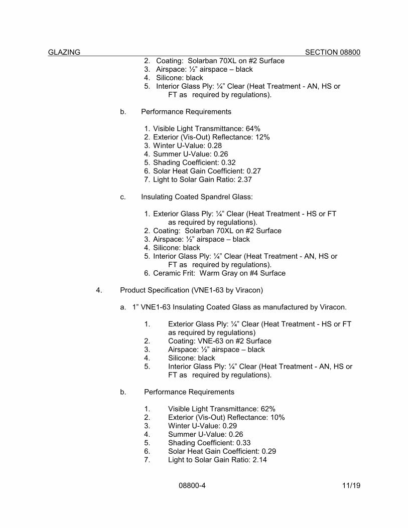
GLAZING SECTION 08800
08800-4 11/19
2. Coating: Solarban 70XL on #2 Surface3. Airspace: ½” airspace – black4. Silicone: black5. Interior Glass Ply: ¼” Clear (Heat Treatment - AN, HS or
FT as required by regulations).
b. Performance Requirements
1. Visible Light Transmittance: 64% 2. Exterior (Vis-Out) Reflectance: 12% 3. Winter U-Value: 0.28 4. Summer U-Value: 0.26 5. Shading Coefficient: 0.32 6. Solar Heat Gain Coefficient: 0.27 7. Light to Solar Gain Ratio: 2.37
c. Insulating Coated Spandrel Glass:
1. Exterior Glass Ply: ¼” Clear (Heat Treatment - HS or FT as required by regulations).
2. Coating: Solarban 70XL on #2 Surface3. Airspace: ½” airspace – black4. Silicone: black5. Interior Glass Ply: ¼” Clear (Heat Treatment - AN, HS or
FT as required by regulations).6. Ceramic Frit: Warm Gray on #4 Surface
4. Product Specification (VNE1-63 by Viracon)
a. 1” VNE1-63 Insulating Coated Glass as manufactured by Viracon.
1. Exterior Glass Ply: ¼” Clear (Heat Treatment - HS or FT as required by regulations)
2. Coating: VNE-63 on #2 Surface3. Airspace: ½” airspace – black4. Silicone: black5. Interior Glass Ply: ¼” Clear (Heat Treatment - AN, HS or
FT as required by regulations).
b. Performance Requirements
1. Visible Light Transmittance: 62%2. Exterior (Vis-Out) Reflectance: 10%3. Winter U-Value: 0.294. Summer U-Value: 0.265. Shading Coefficient: 0.336. Solar Heat Gain Coefficient: 0.297. Light to Solar Gain Ratio: 2.14

GLAZING SECTION 08800
08800-5 11/19
c. Insulating Coated Glass Spandrel Glass:
1. Exterior Glass Ply: ¼” Clear (Heat Treatment - HS or FT as required by regulations).
2. Coating: VNE-63 on #2 Surface3. Airspace: ½” airspace – black4. Silicone: black5. Interior Glass Ply: ¼” Clear (Heat Treatment - AN, HS or
FT as required by regulations).
5. Windows, Storefront and Curtain Wall Units: 1/4" float glass with 1/2" air space for a total thickness of 1".
6. Toilet room, locker room, and shower room units: Same as standard unit, except that one sheet shall be frosted or obscured for translucence
7. Provide tempered insulating glazing at all locations required by code.
B. Tempered Glass: ASTM C1048-85, Kind FT, Condition A, Type I, Class 1, 1/4 inch or 3/8 inch thick, clear, as indicated. Provide wherever tempered glass (T) is indicated or required. Glass shall have a permanent, factory applied identification mark.
C. Float Glass: ASTM C1036, Type I, Class 1, Quality q3, 1/4 inch thick, clear.
D. Fire Rated, impact safety rated glass for fire rated doors, and borrow lites (fire rating requirements range from 20 minutes to 2 hours depending on drawing requirements). Product shall be safety rated glass ceramic glass.
1. Approved Manufacturers:
a. Safety Rated Ceramic Glass:
1) “Firelite Plus”, Nippon Electric Glass Company, Ltd., distributed by Technical Glass Products, Kirkland, WA, 1-800-426-0279, (www.fireglass.com)
2) “Keralite FR-L”, Vetrotech Saint-Gobain, Auburn, WA, 1-888-803-9533, (www.vetrotech.com/us).
3) “Pyran Platinum” by Schott, distributed by Glass Distributors Inc. 301-779-2430
2. Material Characteristics:
a. Ceramic Glass:
1) Thickness: 5/16” (8mm)

GLAZING SECTION 08800
08800-6 11/19
2) Weight: 4lbs./sq.ft.
3) Approximate visible light transmission: 85%
3. Each piece of glass shall be labeled with a permanent manufacturer’s logo, including the product name, fire rating, and testing laboratory logo (Warnock-Hersey International or Underwriters Laboratory).
E. Laminated Glass: ANSI Z97.1, type FT, Class 1, clear plastic P/B interlayer, 1/4" thick. Glass shall have a permanent, factory applied identification mark.
F. Frosted or obscure glass: ANSI Z-97.1, CPSC 16, CFR 1201 Category I and II; provide at all group toilets, gymnasiums and locker rooms or as shown on drawings with windows at exterior walls.
G. Mirrors (Gymnastics): Silverized clear float glass, ¼” thick. Provide safety backing laminate, adhesively bonded to glass.
1. Mirror glass: Comply with ASTM C1048, kind FT coated glass.
2. Safety backing: “CRL Category II Safety Backing Tape”,C.R..Laurence Co., Inc. (www.crlaurence.com). Backing shall comply with ANSI Z971 and CPSC Category II impact rating (400 foot pounds).
H. Acrylic Plastic Glazing: Lexan 9034 high-impact clear ¼” thick glazing; 14% visible light transmission, United States Plastic Corp., AtoGlass or pre-approved equal.
2.02 GLAZING SEALANTS/COMPOUND
A. Provide black exposed glazing materials. Provide hardness of materials as recommended by manufacturer for the required application and condition of installation of each case. Provide only compounds proven to be fully compatible with surfaces contacted. For fire rated glass, provide flame resistant gasket material and glazing tape.
B. Sealant: "50% joint movement capability, UV and weather resistant, primerless adhesion; tested under U. L. 723-79 "Test for Surface Burning Characteristics.
1. Dow Corning 795, Dow Corning Corp., Midland, MI (www.dowcorning.com).
2. “Silglaze II 2800”, GE Sealants and adhesives, 1-866-ASK-GESA (www.gesealants.com).
3. “Spectrem 2”, Tremco Inc., 1-800-321-7906 (www.tremcosealants.com).
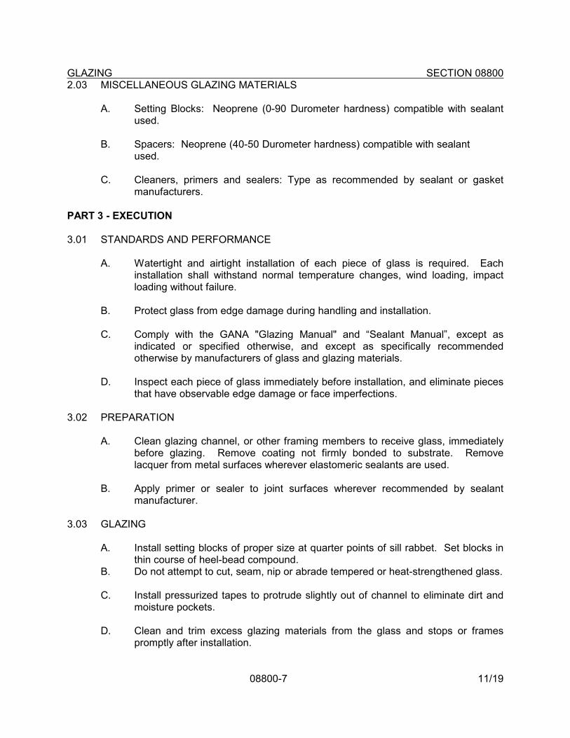
GLAZING SECTION 08800
08800-7 11/19
2.03 MISCELLANEOUS GLAZING MATERIALS
A. Setting Blocks: Neoprene (0-90 Durometer hardness) compatible with sealant used.
B. Spacers: Neoprene (40-50 Durometer hardness) compatible with sealant used.
C. Cleaners, primers and sealers: Type as recommended by sealant or gasket manufacturers.
PART 3 - EXECUTION
3.01 STANDARDS AND PERFORMANCE
A. Watertight and airtight installation of each piece of glass is required. Each installation shall withstand normal temperature changes, wind loading, impact loading without failure.
B. Protect glass from edge damage during handling and installation.
C. Comply with the GANA "Glazing Manual" and “Sealant Manual”, except as indicated or specified otherwise, and except as specifically recommended otherwise by manufacturers of glass and glazing materials.
D. Inspect each piece of glass immediately before installation, and eliminate pieces that have observable edge damage or face imperfections.
3.02 PREPARATION
A. Clean glazing channel, or other framing members to receive glass, immediately before glazing. Remove coating not firmly bonded to substrate. Remove lacquer from metal surfaces wherever elastomeric sealants are used.
B. Apply primer or sealer to joint surfaces wherever recommended by sealant manufacturer.
3.03 GLAZING
A. Install setting blocks of proper size at quarter points of sill rabbet. Set blocks in thin course of heel-bead compound.
B. Do not attempt to cut, seam, nip or abrade tempered or heat-strengthened glass.
C. Install pressurized tapes to protrude slightly out of channel to eliminate dirt and moisture pockets.
D. Clean and trim excess glazing materials from the glass and stops or frames promptly after installation.

GLAZING SECTION 08800
08800-8 11/19
E. Remove and replace glass which is broken, chipped, cracked, abraded or damaged in other ways during construction and including natural causes, accidents and vandalism.
3.04 CLEANING
A. After installation is complete, remove all excess materials such as trash, debris, tools, primers and sealants, and dispose of legally.
END OF SECTION

11/19
INSTRUCTION FOR EDITING
SECTION 08810
GLAZING
1. This section to be used for projects dealing with Additions only (No Renovation). Consult with D&C staff to make sure that low-e glazing is not required.
2. Page 08800-2 and 08800-3, Paragraph 2.01: Edit glass types to delete any types not applicable to project.

08810-1 11/19
SECTION 08810
GLAZING
PART 1 - GENERAL
1.01 RELATED DOCUMENTS
A. Drawings and General Provisions of Contract, including General Conditions and other Division 1 Specification Sections, apply to the Work of this Section.
1.02 RELATED WORK
A. Warranties and Bonds: Section 01740.
B. Metal Doors and Frames: Section 08100.
C. Wood Doors: Section 08210.
D. Entrances and Storefronts: Section 08400.
E. Aluminum Windows: Section 08520.
1.03 REFERENCE STANDARDS
A. Safety Standard for Architectural Glazing Materials, CPSC, Title 16, Part 1201 of the Code of Federal Regulations.
B. ANSI Z 97.1 (1984), American National Standard for Safety Glazing Materials Used in Buildings.
C. Glazing Standards: Glass Association of North America (GANA) “Glazing Manual” and “Sealant Manual”.
1.04 SUBMITTALS
A. Submit copies of manufacturer's specifications, technical data and installation instructions for each type of glass required. Include test data substantiating that glass complies with specified requirements, including UL product classifications for fire rated safety glazing.
B. Submit samples of each type of glass specified.
C. Submit samples of glazing sealants, tape, and setting blocks.

GLAZING SECTION 08810
08810-2 11/19
1.05 DELIVERY AND STORAGE
A. Deliver glass to site in suitable containers that will protect glass from weather and breakage.
B. Standard Glass: Provide labels showing glass manufacturers' identity, type of glass, thickness and quality on each piece of glass. Label shall remain on glass until glass has been set and inspected. Certificates will be accepted in lieu of labels for shop or job cut glass. See special requirements listed in 1.05 below for non-rated and fire rated safety glass.
C. Glazing materials shall arrive at project site in manufacturer’s original, unopened and labeled containers.
1.06 QUALITY ASSURANCE
A. Non-rated Safety glass: comply with ANSI Z97.1 and CPSC 16 CFR 1201, category I & II for door glass, and bear a permanent, factory applied identification label on each piece.
B. Fire rated safety glass: Comply with the following:
1. Impact safety rating: CPSC 16 CFR1201, Categories I and II.
2. Positive Pressure Test: UL 10C – Positive.Pressure Fire Tests of Door Assemblies.
3. UL 9 – Fire Tests of Window Assemblies.
C. Glazing: Comply with recommendations of the GANA "Glazing Manual" and "Sealant Manual” (www.glasswebsite.com).
1.07 WARRANTIES
A. Provide a two (2) year written warranty on glazing installation, and a five (5) year warranty upon the hermetic seal of the insulating glass (no visual obstruction due to internal moisture). Fire rated safety glass shall have the Manufacturer’s standard five (5) year limited warranty
PART 2 - PRODUCTS
2.01 GLASS
A. Insulating Glass: Meet requirements of SIGMA for class CBA rating in accordance with ASTM E773 and E774. Provide units of 2 sheets of clear annealed or float glass as indicated, permanently and hermetically sealed
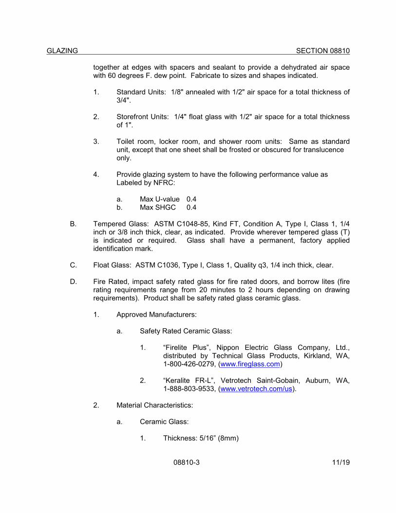
GLAZING SECTION 08810
08810-3 11/19
together at edges with spacers and sealant to provide a dehydrated air space with 60 degrees F. dew point. Fabricate to sizes and shapes indicated.
1. Standard Units: 1/8" annealed with 1/2" air space for a total thickness of 3/4".
2. Storefront Units: 1/4" float glass with 1/2" air space for a total thickness of 1".
3. Toilet room, locker room, and shower room units: Same as standard unit, except that one sheet shall be frosted or obscured for translucence
only.
4. Provide glazing system to have the following performance value asLabeled by NFRC:
a. Max U-value 0.4b. Max SHGC 0.4
B. Tempered Glass: ASTM C1048-85, Kind FT, Condition A, Type I, Class 1, 1/4 inch or 3/8 inch thick, clear, as indicated. Provide wherever tempered glass (T) is indicated or required. Glass shall have a permanent, factory applied identification mark.
C. Float Glass: ASTM C1036, Type I, Class 1, Quality q3, 1/4 inch thick, clear.
D. Fire Rated, impact safety rated glass for fire rated doors, and borrow lites (fire rating requirements range from 20 minutes to 2 hours depending on drawing requirements). Product shall be safety rated glass ceramic glass.
1. Approved Manufacturers:
a. Safety Rated Ceramic Glass:
1. “Firelite Plus”, Nippon Electric Glass Company, Ltd., distributed by Technical Glass Products, Kirkland, WA, 1-800-426-0279, (www.fireglass.com)
2. “Keralite FR-L”, Vetrotech Saint-Gobain, Auburn, WA, 1-888-803-9533, (www.vetrotech.com/us).
2. Material Characteristics:
a. Ceramic Glass:
1. Thickness: 5/16” (8mm)
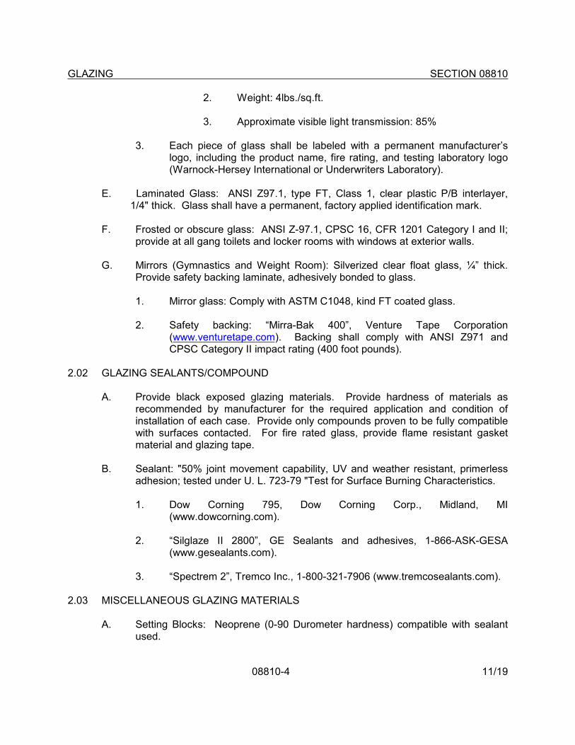
GLAZING SECTION 08810
08810-4 11/19
2. Weight: 4lbs./sq.ft.
3. Approximate visible light transmission: 85%
3. Each piece of glass shall be labeled with a permanent manufacturer’s logo, including the product name, fire rating, and testing laboratory logo (Warnock-Hersey International or Underwriters Laboratory).
E. Laminated Glass: ANSI Z97.1, type FT, Class 1, clear plastic P/B interlayer, 1/4" thick. Glass shall have a permanent, factory applied identification mark.
F. Frosted or obscure glass: ANSI Z-97.1, CPSC 16, CFR 1201 Category I and II; provide at all gang toilets and locker rooms with windows at exterior walls.
G. Mirrors (Gymnastics and Weight Room): Silverized clear float glass, ¼” thick. Provide safety backing laminate, adhesively bonded to glass.
1. Mirror glass: Comply with ASTM C1048, kind FT coated glass.
2. Safety backing: “Mirra-Bak 400”, Venture Tape Corporation (www.venturetape.com). Backing shall comply with ANSI Z971 and CPSC Category II impact rating (400 foot pounds).
2.02 GLAZING SEALANTS/COMPOUND
A. Provide black exposed glazing materials. Provide hardness of materials as recommended by manufacturer for the required application and condition of installation of each case. Provide only compounds proven to be fully compatible with surfaces contacted. For fire rated glass, provide flame resistant gasket material and glazing tape.
B. Sealant: "50% joint movement capability, UV and weather resistant, primerless adhesion; tested under U. L. 723-79 "Test for Surface Burning Characteristics.
1. Dow Corning 795, Dow Corning Corp., Midland, MI (www.dowcorning.com).
2. “Silglaze II 2800”, GE Sealants and adhesives, 1-866-ASK-GESA (www.gesealants.com).
3. “Spectrem 2”, Tremco Inc., 1-800-321-7906 (www.tremcosealants.com).
2.03 MISCELLANEOUS GLAZING MATERIALS
A. Setting Blocks: Neoprene (0-90 Durometer hardness) compatible with sealant used.

GLAZING SECTION 08810
08810-5 11/19
B. Spacers: Neoprene (40-50 Durometer hardness) compatible with sealant used.
C. Cleaners, primers and sealers: Type as recommended by sealant or gasket manufacturers.
PART 3 - EXECUTION
3.01 STANDARDS AND PERFORMANCE
A. Watertight and airtight installation of each piece of glass is required. Each installation shall withstand normal temperature changes, wind loading, impact loading without failure.
B. Protect glass from edge damage during handling and installation.
C. Comply with the GANA "Glazing Manual" and “Sealant Manual”, except as indicated or specified otherwise, and except as specifically recommended otherwise by manufacturers of glass and glazing materials.
D. Inspect each piece of glass immediately before installation, and eliminate pieces that have observable edge damage or face imperfections.
3.02 PREPARATION
A. Clean glazing channel, or other framing members to receive glass, immediately before glazing. Remove coating not firmly bonded to substrate. Remove lacquer from metal surfaces wherever elastomeric sealants are used.
B. Apply primer or sealer to joint surfaces wherever recommended by sealant manufacturer.
3.03 GLAZING
A. Install setting blocks of proper size at quarter points of sill rabbet. Set blocks in thin course of heel-bead compound.
B. Do not attempt to cut, seam, nip or abrade tempered or heat-strengthened glass.
C. Install pressurized tapes to protrude slightly out of channel to eliminate dirt and moisture pockets.
D. Clean and trim excess glazing materials from the glass and stops or frames promptly after installation.

GLAZING SECTION 08810
08810-6 11/19
E. Remove and replace glass which is broken, chipped, cracked, abraded or damaged in other ways during construction and including natural causes, accidents and vandalism.
3.04 CLEANING
A. After installation is complete, remove all excess materials such as trash, debris, tools, primers and sealants, and dispose of legally.
END OF SECTION


![Louvers Selection[1]](https://img.pdfslide.us/doc/110x75/577c7f031a28abe054a2dc2f/louvers-selection1.jpg)