Embed Size (px)
Citation preview
IM05805003K
Effective January 2003
Instructions for Cutler-Hammer Diesel Engine Fire Pump Controllers

IM05805003K Page i
Effective January 2003
Table of Contents1. INSTALLATION AND MOUNTING OF CONTROLLER............................................................. 1
2. ELECTRICAL CONNECTIONS ....................................................................................................... 1
2.1 WIRE SIZES....................................................................................................................................... 1
3. SYSTEM PRESSURE CONNECTION.............................................................................................. 2
4. MAIN DISPLAY PANEL .................................................................................................................... 2
4.1 LCD DISPLAY.................................................................................................................................... 24.2 ANNUNCIATORS ............................................................................................................................... 24.3 MAIN SWITCH................................................................................................................................... 24.4 FUNCTION (F1, F2, F3) AND MENU KEYS .......................................................................................... 24.5 SILENCE AND RESET BUTTON ........................................................................................................... 24.6 LAMP TEST BUTTON ......................................................................................................................... 24.7 TIME/PRINT BUTTON ........................................................................................................................ 2
5. OPERATION OF CONTROLLER .................................................................................................... 3
5.1 OFF MODE ........................................................................................................................................ 35.2 MANUAL MODE ................................................................................................................................ 35.3 AUTO MODE ..................................................................................................................................... 35.4 STOP MODES .................................................................................................................................... 35.5 WEEKLY TEST TIMER........................................................................................................................ 35.6 TEST MODE ...................................................................................................................................... 45.7 RUN PERIOD TIMER (RPT) ................................................................................................................. 45.8 SEQUENTIAL START TIMER............................................................................................................... 4
6. PROGRAMMING THE MAIN CONTROLLER ............................................................................. 5
6.1 TO PROGRAM THE CONTROLLER....................................................................................................... 56.2 PROGRAM DECRIPTIONS ................................................................................................................... 5
6.2.1 Change Date ........................................................................................................................... 56.2.2 Change time............................................................................................................................ 56.2.3 Weekly Timer .......................................................................................................................... 56.2.4 Run Period Timer ................................................................................................................... 56.2.5 Language ................................................................................................................................ 56.2.6 Pressure Transducer............................................................................................................... 66.2.7 Pressure Start Pt..................................................................................................................... 66.2.8 Pressure Stop Pt ..................................................................................................................... 66.2.9 Low Suction Shutdown............................................................................................................ 66.2.10 Printer Deviation .................................................................................................................... 66.2.11 Current Pressure .................................................................................................................... 66.2.12 Sequential Start....................................................................................................................... 66.2.13 Stop Mode ............................................................................................................................... 66.2.14 AC Failure Start ..................................................................................................................... 66.2.15 Print Routine........................................................................................................................... 76.2.16 Print Status ............................................................................................................................. 76.2.17 Select Mode or Press Menu .................................................................................................... 7
7. ALARM SIGNALS............................................................................................................................... 8
7.1 BATTERY FAILURE ........................................................................................................................... 87.2 CHARGER FAILURE........................................................................................................................... 87.3 ENGINE RUN..................................................................................................................................... 87.4 ENGINE OVERSPEED ......................................................................................................................... 87.5 FAIL TO START ................................................................................................................................. 87.6 RELIEF VALVE DISCHARGE............................................................................................................... 87.7 HIGH ENGINE TEMPERATURE............................................................................................................ 8
Page ii IM05805003K
Effective January 2003
7.8 LOW / HIGH FUEL ............................................................................................................................. 87.9 LOW OIL PRESSURE .......................................................................................................................... 87.10 LOW / HIGH RESERVOIR.................................................................................................................... 87.11 LOW ROOM TEMPERATURE............................................................................................................... 8
8. BATTERY CHARGERS ..................................................................................................................... 9
9. OPERATING TEMPERATURE ........................................................................................................ 9
10. INITIAL START UP.......................................................................................................................... 10
10.1 AUTOMATIC START TEST................................................................................................................ 1010.2 MANUAL START TEST..................................................................................................................... 1110.3 TEST START TEST ........................................................................................................................... 1110.4 WEEKLY EXERCISER TEST .............................................................................................................. 11
11. FIELD FAILURE ALARM SIMULATION .................................................................................... 12
11.1 CHARGER FAILURE......................................................................................................................... 1211.2 BATTERY FAILURE ......................................................................................................................... 1211.3 LOW OIL PRESSURE ........................................................................................................................ 1211.4 HIGH ENGINE TEMPERATURE.......................................................................................................... 1211.5 ENGINE FAIL TO START................................................................................................................... 1211.6 ENGINE OVERSPEED ....................................................................................................................... 1211.7 OTHER ALARMS (PUMP ROOM ALARMS) ......................................................................................... 12
12. PRINTER - RECORDER INSTRUCTIONS............................................................................... 13
12.1 OPERATING PROCEDURE ................................................................................................................ 1312.2 SELF TEST FUNCTION ..................................................................................................................... 1312.3 PAPER LOADING ............................................................................................................................. 1312.4 PRINT MODES ................................................................................................................................. 14
12.4.1 Auto Print ............................................................................................................................. 1412.4.2 Manual Print......................................................................................................................... 14
12.5 PRINT STATUS ................................................................................................................................ 1412.6 PRINTER DEVIATION....................................................................................................................... 1412.7 REPLACEMENT PAPER TYPE............................................................................................................ 15
13. FACEPLATE DETAILS................................................................................................................. 16
14. MENU FLOWCHART .................................................................................................................. 17
15. APPENDIX A: ANNUNCIATOR ALARMS.............................................................................. 18
16. APPENDIX B: PRINTER 'EVENT' MESSAGES ..................................................................... 19
17. DIMENSIONS AND SHIPPING WEIGHT................................................................................. 20
18. FIELD CONNECTIONS, TERMINAL BLOCK ........................................................................ 21
19. TYPICAL SCHEMATIC............................................................................................................... 22
IM05805003K Page 1
Effective January 2003
Installation & MaintenanceManual for Diesel Engine
Fire Pump ControllerIn order to familiarize yourself with the FD100 Diesel Controller, please read this instructionmanual thoroughly and carefully. Retain the manual for future reference.
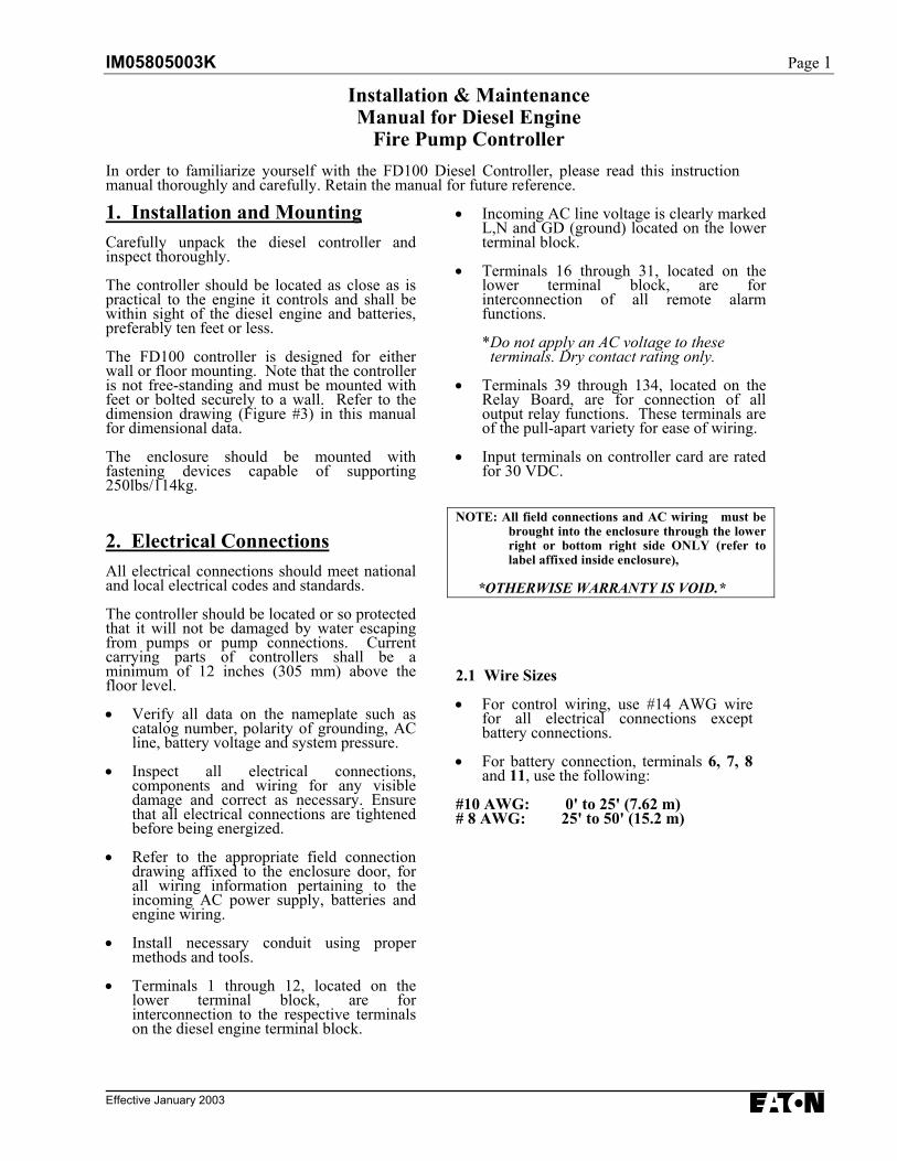
1. Installation and MountingCarefully unpack the diesel controller andinspect thoroughly.
The controller should be located as close as ispractical to the engine it controls and shall bewithin sight of the diesel engine and batteries,preferably ten feet or less.
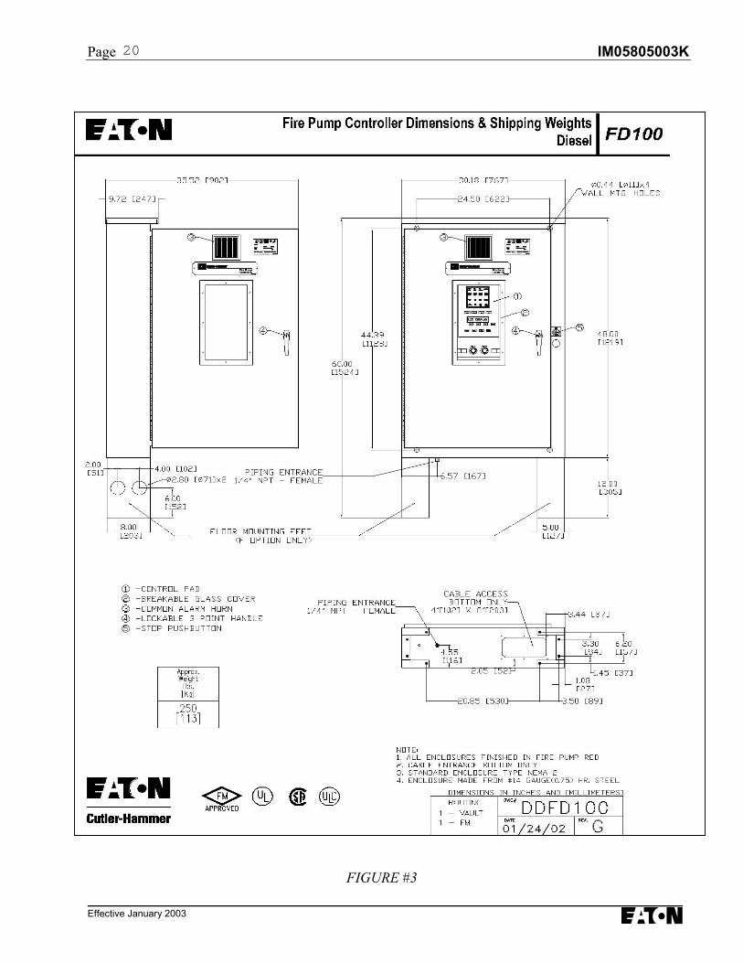
The FD100 controller is designed for eitherwall or floor mounting. Note that the controlleris not free-standing and must be mounted withfeet or bolted securely to a wall. Refer to thedimension drawing (Figure #3) in this manualfor dimensional data.
The enclosure should be mounted withfastening devices capable of supporting250lbs/114kg.
2. Electrical ConnectionsAll electrical connections should meet nationaland local electrical codes and standards.
The controller should be located or so protectedthat it will not be damaged by water escapingfrom pumps or pump connections. Currentcarrying parts of controllers shall be aminimum of 12 inches (305 mm) above thefloor level.
• Verify all data on the nameplate such ascatalog number, polarity of grounding, ACline, battery voltage and system pressure.
• Inspect all electrical connections,components and wiring for any visibledamage and correct as necessary. Ensurethat all electrical connections are tightenedbefore being energized.
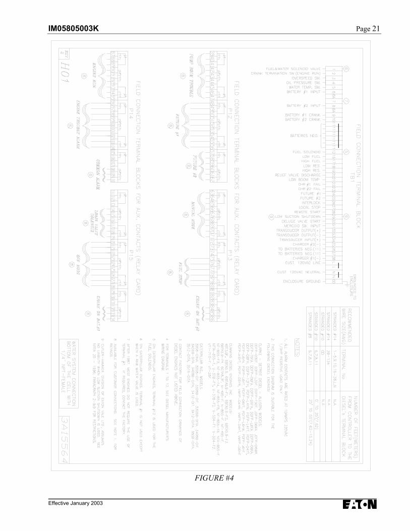
• Refer to the appropriate field connectiondrawing affixed to the enclosure door, forall wiring information pertaining to theincoming AC power supply, batteries andengine wiring.
• Install necessary conduit using propermethods and tools.
• Terminals 1 through 12, located on thelower terminal block, are forinterconnection to the respective terminalson the diesel engine terminal block.
• Incoming AC line voltage is clearly markedL,N and GD (ground) located on the lowerterminal block.
• Terminals 16 through 31, located on thelower terminal block, are forinterconnection of all remote alarmfunctions.
*Do not apply an AC voltage to these terminals. Dry contact rating only.
• Terminals 39 through 134, located on theRelay Board, are for connection of alloutput relay functions. These terminals areof the pull-apart variety for ease of wiring.
• Input terminals on controller card are ratedfor 30 VDC.
NOTE: All field connections and AC wiring must bebrought into the enclosure through the lowerright or bottom right side ONLY (refer tolabel affixed inside enclosure),
*OTHERWISE WARRANTY IS VOID.*
2.1 Wire Sizes
• For control wiring, use #14 AWG wirefor all electrical connections exceptbattery connections.
• For battery connection, terminals 6, 7, 8and 11, use the following:
#10 AWG: 0' to 25' (7.62 m)# 8 AWG: 25' to 50' (15.2 m)
Page 2 IM05805003K
Effective January 2003
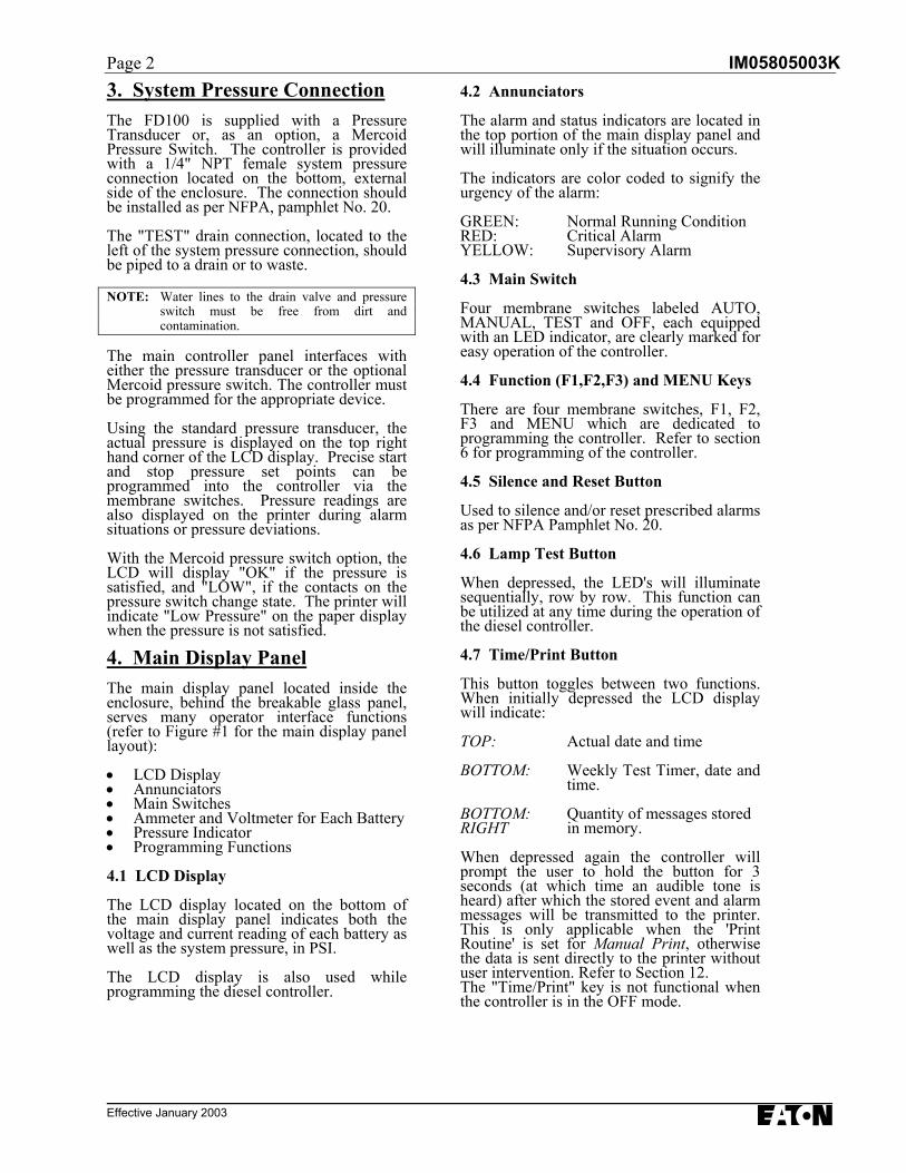
3. System Pressure ConnectionThe FD100 is supplied with a PressureTransducer or, as an option, a MercoidPressure Switch. The controller is providedwith a 1/4" NPT female system pressureconnection located on the bottom, externalside of the enclosure. The connection shouldbe installed as per NFPA, pamphlet No. 20.
The "TEST" drain connection, located to theleft of the system pressure connection, shouldbe piped to a drain or to waste.
NOTE: Water lines to the drain valve and pressureswitch must be free from dirt andcontamination.
The main controller panel interfaces witheither the pressure transducer or the optionalMercoid pressure switch. The controller mustbe programmed for the appropriate device.
Using the standard pressure transducer, theactual pressure is displayed on the top righthand corner of the LCD display. Precise startand stop pressure set points can beprogrammed into the controller via themembrane switches. Pressure readings arealso displayed on the printer during alarmsituations or pressure deviations.
With the Mercoid pressure switch option, theLCD will display "OK" if the pressure issatisfied, and "LOW", if the contacts on thepressure switch change state. The printer willindicate "Low Pressure" on the paper displaywhen the pressure is not satisfied.
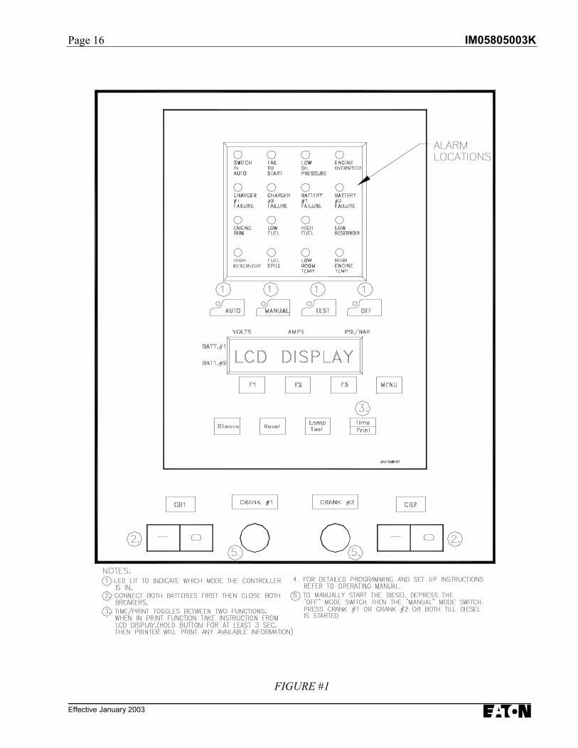
4. Main Display PanelThe main display panel located inside theenclosure, behind the breakable glass panel,serves many operator interface functions(refer to Figure #1 for the main display panellayout):
• LCD Display• Annunciators• Main Switches• Ammeter and Voltmeter for Each Battery• Pressure Indicator• Programming Functions
4.1 LCD Display
The LCD display located on the bottom ofthe main display panel indicates both thevoltage and current reading of each battery aswell as the system pressure, in PSI.
The LCD display is also used whileprogramming the diesel controller.
4.2 Annunciators
The alarm and status indicators are located inthe top portion of the main display panel andwill illuminate only if the situation occurs.
The indicators are color coded to signify theurgency of the alarm:
GREEN: Normal Running ConditionRED: Critical AlarmYELLOW: Supervisory Alarm
4.3 Main Switch
Four membrane switches labeled AUTO,MANUAL, TEST and OFF, each equippedwith an LED indicator, are clearly marked foreasy operation of the controller.
4.4 Function (F1,F2,F3) and MENU Keys
There are four membrane switches, F1, F2,F3 and MENU which are dedicated toprogramming the controller. Refer to section6 for programming of the controller.
4.5 Silence and Reset Button
Used to silence and/or reset prescribed alarmsas per NFPA Pamphlet No. 20.
4.6 Lamp Test Button
When depressed, the LED's will illuminatesequentially, row by row. This function canbe utilized at any time during the operation ofthe diesel controller.
4.7 Time/Print Button
This button toggles between two functions.When initially depressed the LCD displaywill indicate:
TOP: Actual date and time
BOTTOM: Weekly Test Timer, date andtime.
BOTTOM: Quantity of messages storedRIGHT in memory.
When depressed again the controller willprompt the user to hold the button for 3seconds (at which time an audible tone isheard) after which the stored event and alarmmessages will be transmitted to the printer.This is only applicable when the 'PrintRoutine' is set for Manual Print, otherwisethe data is sent directly to the printer withoutuser intervention. Refer to Section 12.The "Time/Print" key is not functional whenthe controller is in the OFF mode.
IM05805003K Page 3
Effective January 2003
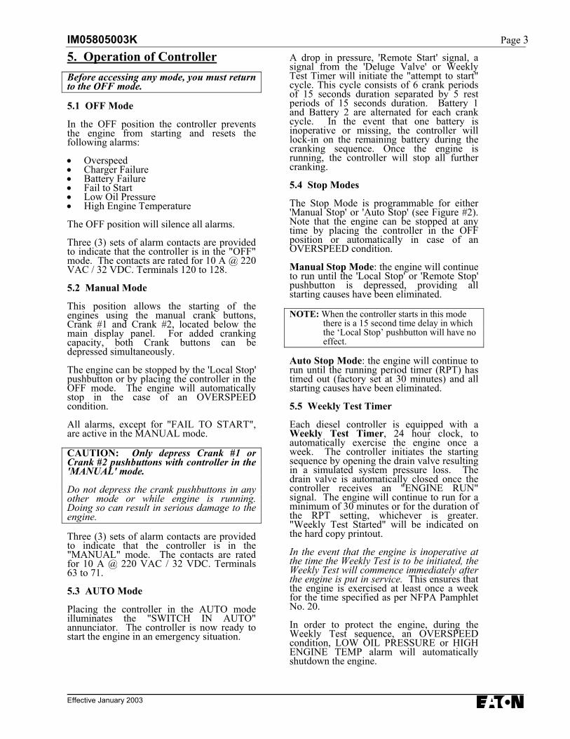
5. Operation of ControllerBefore accessing any mode, you must returnto the OFF mode.
5.1 OFF Mode
In the OFF position the controller preventsthe engine from starting and resets thefollowing alarms:
• Overspeed• Charger Failure• Battery Failure• Fail to Start• Low Oil Pressure• High Engine Temperature
The OFF position will silence all alarms.
Three (3) sets of alarm contacts are providedto indicate that the controller is in the "OFF"mode. The contacts are rated for 10 A @ 220VAC / 32 VDC. Terminals 120 to 128.
5.2 Manual Mode
This position allows the starting of theengines using the manual crank buttons,Crank #1 and Crank #2, located below themain display panel. For added crankingcapacity, both Crank buttons can bedepressed simultaneously.
The engine can be stopped by the 'Local Stop'pushbutton or by placing the controller in theOFF mode. The engine will automaticallystop in the case of an OVERSPEEDcondition.
All alarms, except for "FAIL TO START",are active in the MANUAL mode.
CAUTION: Only depress Crank #1 orCrank #2 pushbuttons with controller in the'MANUAL' mode.
Do not depress the crank pushbuttons in anyother mode or while engine is running.Doing so can result in serious damage to theengine.
Three (3) sets of alarm contacts are providedto indicate that the controller is in the"MANUAL" mode. The contacts are ratedfor 10 A @ 220 VAC / 32 VDC. Terminals63 to 71.
5.3 AUTO Mode
Placing the controller in the AUTO modeilluminates the "SWITCH IN AUTO"annunciator. The controller is now ready tostart the engine in an emergency situation.
A drop in pressure, 'Remote Start' signal, asignal from the 'Deluge Valve' or WeeklyTest Timer will initiate the "attempt to start"cycle. This cycle consists of 6 crank periodsof 15 seconds duration separated by 5 restperiods of 15 seconds duration. Battery 1and Battery 2 are alternated for each crankcycle. In the event that one battery isinoperative or missing, the controller willlock-in on the remaining battery during thecranking sequence. Once the engine isrunning, the controller will stop all furthercranking.
5.4 Stop Modes
The Stop Mode is programmable for either'Manual Stop' or 'Auto Stop' (see Figure #2).Note that the engine can be stopped at anytime by placing the controller in the OFFposition or automatically in case of anOVERSPEED condition.
Manual Stop Mode: the engine will continueto run until the 'Local Stop' or 'Remote Stop'pushbutton is depressed, providing allstarting causes have been eliminated.
NOTE: When the controller starts in this modethere is a 15 second time delay in whichthe ‘Local Stop’ pushbutton will have noeffect.
Auto Stop Mode: the engine will continue torun until the running period timer (RPT) hastimed out (factory set at 30 minutes) and allstarting causes have been eliminated.
5.5 Weekly Test Timer
Each diesel controller is equipped with aWeekly Test Timer, 24 hour clock, toautomatically exercise the engine once aweek. The controller initiates the startingsequence by opening the drain valve resultingin a simulated system pressure loss. Thedrain valve is automatically closed once thecontroller receives an "ENGINE RUN"signal. The engine will continue to run for aminimum of 30 minutes or for the duration ofthe RPT setting, whichever is greater."Weekly Test Started" will be indicated onthe hard copy printout.
In the event that the engine is inoperative atthe time the Weekly Test is to be initiated, theWeekly Test will commence immediately afterthe engine is put in service. This ensures thatthe engine is exercised at least once a weekfor the time specified as per NFPA PamphletNo. 20.
In order to protect the engine, during theWeekly Test sequence, an OVERSPEEDcondition, LOW OIL PRESSURE or HIGHENGINE TEMP alarm will automaticallyshutdown the engine.
Page 4 IM05805003K
Effective January 2003
5.6 TEST Mode
Placing the controller in the TEST positioninitiates a starting sequence by opening thedrain valve resulting in a pressure loss. Thecontroller will start the engine in theautomatic mode.
The TEST sequence can be terminated byputting the controller in the OFF mode,otherwise the STOP mode prevails asprogrammed.
All alarms are active in the test mode. Inorder to protect the engine, in the test mode,an OVERSPEED condition, LOW OILPRESSURE or HIGH ENGINE TEMP alarmwill automatically shutdown the engine.
5.7 Run Period Timer
The Run Period Timer (RPT) performs theautomatic stopping function in a Fire PumpController after a start initiated by thepressure switch during automatic operation.
The purpose of the RPT is to ensure that theengine is not subjected to frequent starts inresponse to the pressure. Refer to Section 6for programming of the RPT.
5.8 Sequential Start Timer
The Sequential Start Timer is standard in alldiesel fire pump controllers.
“The controller for each unit of multiplepump units operating in parallel shallincorporate a sequential timing device toprevent any one motor from startingsimultaneously with any other motor. Ifwater requirements call for more than onepumping unit to operate, the units shall startat intervals of 5 to 10 seconds. Failure of aleading motor to start shall not preventsubsequent pumping units from starting” –NFPA, Pamphlet 20, Chapter 7.
The sequential start timer (SST) delays thestarting of a fire pump in response to thepressure switch. It does not delay apushbutton or emergency handle start..
With a SST in each controller, any pump maybe selected as the lead pump by appropriatesetting of the timers. If the lead pumprestores the pressure in less than the time
delays applied to the lag pumps, then the lagpumps will not start.
In addition, the provision of a sequential starttimer, set to a few seconds delay, will preventthe lead pump controller from responding tomomentary hydraulic transient pressure losswhich would otherwise start the fire pumpunnecessarily.
The SST can be programmed from 0 – 300seconds. Typically, each pump should bedelayed by 10 seconds from the pump aheadof it. If hydraulic transients are a problem,all timers can be adjusted for a few secondsextra time delay.
IM05805003K Page 5
Effective January 2003
6. Programming of the MainController
>> The controller is programmable << in the 'OFF' mode only
The LCD display will prompt theprogrammer with data and allow the operatorto modify the program using a combinationof the MENU key and three function keys;F1, F2 and F3. The displayed parametervalue indicates the present setting of thecontroller. Located above the F1, F2 & F3keys are designated symbols and/or wordsdescribing their function. The function keysare used to increase, decrease or accept presetvalues.
While programming, a Function key or theMENU key must be depressed within a 60second time period, otherwise the controllerwill return to the initial prompt.
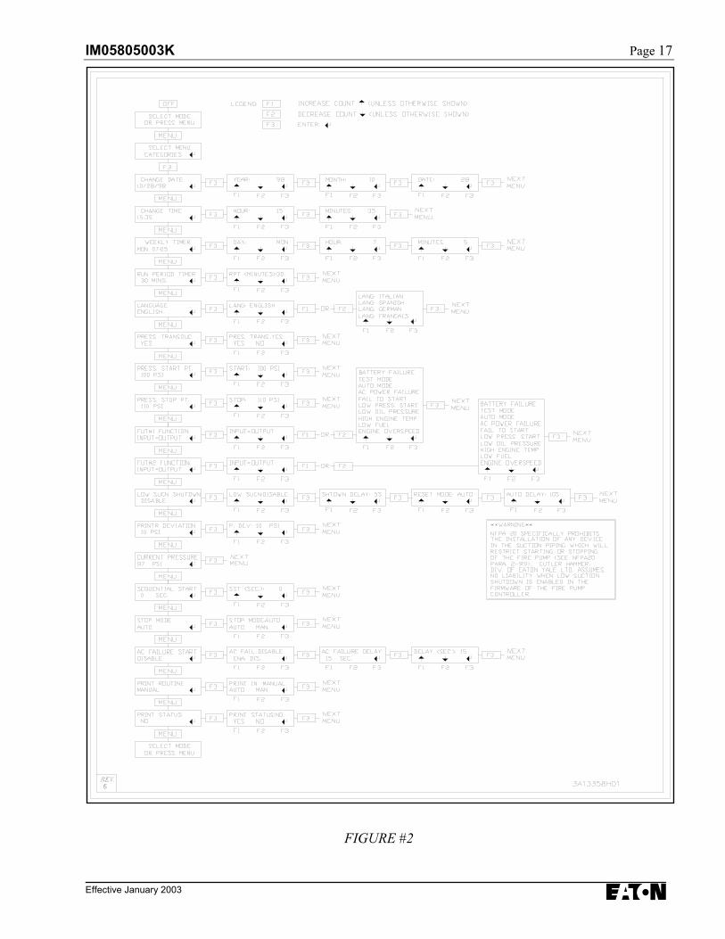
6.1 To Program The Controller
Place the controller in the 'OFF' mode anddepress the MENU key, followed by the F3key. Figure #2 (Page 17) illustrates thesequence in which the operator is promptedfor each parameter. To move to the nextparameter, press the MENU key. Note thatmoving from one parameter to the next doesnot affect the value of the parameter currentlydisplayed.
F1 and F2 are used to change the value whileF3 is used to enter the value into memory oraccept the present value and proceed to thenext parameter.
For example, if the parameter displayed is"CHANGE DATE", press the MENU keythree (3) times to access the "RUN PERIODTIMER" parameter and press F3 to changethe time. F1 increases the count, F2decreases the count and F3 enters the selectedvalue into memory and proceeds to the nextparameter.
PROGRAMMABLE RANGES
Run Period Timer: 1-60 minsPressure (Start/Stop): 1-500 PSIPressure Deviation: 1-100 PSIAC Failure Delay: 0-300 secSequential Start Timer: 0-300 secLow Suction Shutdown YES or NO
6.2 Program Descriptions
Refer to Appendix A attached .
6.2.1 Change Date
Factory set, however, this parameter allowsthe user to set the current date.
6.2.2 Change Time
Factory set, however, this parameter allowsthe user to set the current time.
6.2.3 Weekly Timer
This function allows the user to set thecontroller to automatically start and stop theengine once per week. Select the day andtime (24-hour clock) for the engine to run.Once selected, choose the run time desired, inminutes. The engine will now start once perweek as programmed. The engine will runfor a minimum of 30 minutes or for theduration of the RPT setting, whichever isgreater.
You can view the status of the Weekly Testdate by depressing the TIME/PRINT buttontwice.
6.2.4 Run Period Timer
To activate the RPT, the STOP MODEfunction must be ‘Set for Automatic’ (seebelow in this section). When the engine isstarted in response to the pressure switch, itwill continue to run for the duration of theRPT, in minutes. Once timed out, if nofurther starting causes prevail, the engine willautomatically stop.
If the engine is started manually the RPT hasno affect and the engine must be stoppedmanually.
If the STOP MODE function is ‘Set forManual’, the RPT does not affect theoperation of the controller and becomesinoperative.
The timing range for the RPT is: 1-60 mins
Note: that the RPT timer must be reset to thirty(30) minutes when the controller is placed inservice.
6.2.5 Language
The language can be selected for eitherEnglish, Spanish or French.
Page 6 IM05805003K
Effective January 2003
6.2.6 Pressure Transducer
When selected as YES, the controller willstart based on the signal from the pressuretransducer.
When selected as NO, the engine will startwhen the controller detects a contact closurebetween terminals 31+11, i.e. Mercoidpressure switch start.
For both starting conditions above, theSequential Start Timer is activated whenselected.
6.2.7 Pressure Start Pt
The value programmed determines at whatpressure the controller will initiate a startcommand to the engine.
The pressure range is: 1-500 PSI
6.2.8 Pressure Stop Pt
The value programmed determines at whatpressure the system must reach before thecontroller will STOP the engine, eithermanually via the STOP pushbutton orautomatically via the RPT timer. If the actualpressure does not exceed the STOP pressurevalue, the engine will continue to run.
The pressure range is: 1-500 PSI
6.2.9 Low Suction Shutdown
This function monitors a contact closurebetween terminals 29+11. If shutdown isdisabled, the LCD display will show lowsuction and the engine will continue to run.
If shutdown is enabled, to prevent thecontroller from responding to momentaryhydraulic transient pressure loss (whichwould otherwise shut down the engineunnecessarily), a time delay must beprogrammed to ensure a steady state.
The shutdown time delay is selectablebetween 0-30 seconds. Upon detecting asteady state contact closure, the engine willturn off.
The reset mode of the engine is userselectable. For AUTOMATIC reset, a timedelay between 0- 30 seconds is selected, afterwhich the controller observes the input for atrue signal, and if true, will not allow theengine to restart. If false, the controller willfunction as normal and respond to a startsignal.
If MANUAL reset is selected, the RESETpushbutton must be depressed to reset thecontroller. If the situation continues to exist,the controller will not restart the engine andthe alarm will reappear.
The LCD display will indicate ‘Low SuctionShutdown’ in both situations.
NFPA 20, Section 2-9.9, specifically prohibits theinstallation of any device in the suction pipingthat will restrict starting or stopping of the firepump. Cutler-Hammer assumes no liability whenthis function is used.
6.2.10 Printer Deviation
This value determines how often to printsystem pressure fluctuations as programmedby the user. In effect, it performs as a chartrecorder.
For example, if 10 PSI is programmed, eachtime the system pressure fluctuates by 10PSI, up or down, the actual pressure isrecorded in memory and printed, tagged witha date and time. This method avoidscontinual, time-based printing of unnecessarypressure values.
6.2.11 Current Pressure
Allows the user to view the actual pressureduring programming of the Diesel Controller.
6.2.12 Sequential Start
This parameter allows you to program a startdelay after a start request. To bypass the startdelay, set the parameter to zero.
The programmable range is: 0-300 sec
6.2.13 Stop Mode
If ‘Set for Manual’, once started, the engineMUST be stopped manually by depressingthe STOP pushbutton located on the flange,regardless of the starting cause. If ‘Set forAuto’, the RPT becomes operative.
6.2.14 AC Failure Start
If ‘Enabled’, the controller will automaticallystart upon the loss of AC power. There willbe a non-adjustable delay of 180 secondsbefore the AC failure is detected. Anadditional delay can be set if desired. Timerange is between 0 & 300 seconds. If‘disabled’ AC power failure will have noaffect on the starting of the engine.
IM05805003K Page 7
Effective January 2003
6.2.15 Print Routine
If selected for Auto, the messages will printimmediately without any user intervention.
If selected for Manual, the messages will bestored in the controller’s memory and willprint once the TIME/PRINT key is pushedand held for 3 seconds.
To avoid paper build up inside the enclosure,it is recommended that the print mode beselected as ‘MANUAL’ during normaloperation of the controller.
6.2.16 Print Status
If selected as ‘NO’, a Status report will notprint when exiting the programming menu. Ifselected as ‘YES’, after exiting the programmode, and pressing the Time/Print button for3 seconds, the programmed parameters andselected controller readings will be printed.This is most helpful during and aftercommissioning of the Fire Pump Controller.A sample status printout is shown in section12:
6.2.17 Select Mode or Press Menu
If programming of the unit is completepressing the mode keys will put the controllerback into operation.
Page 8 IM05805003K
Effective January 2003
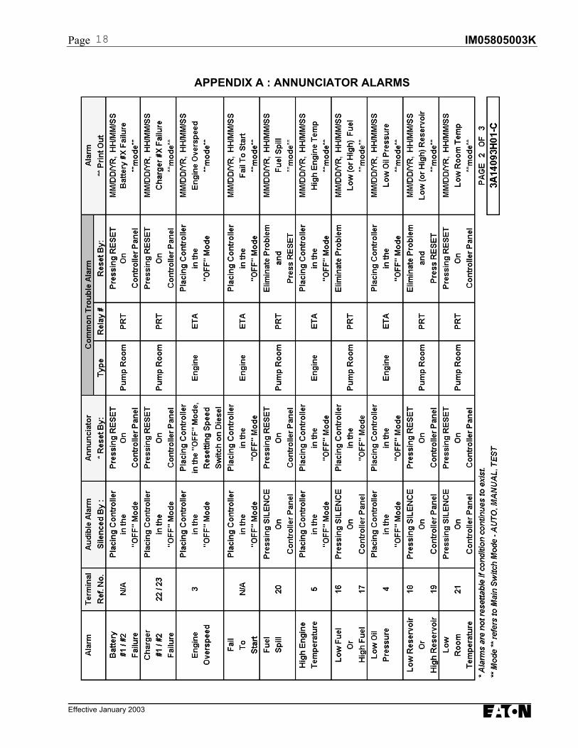
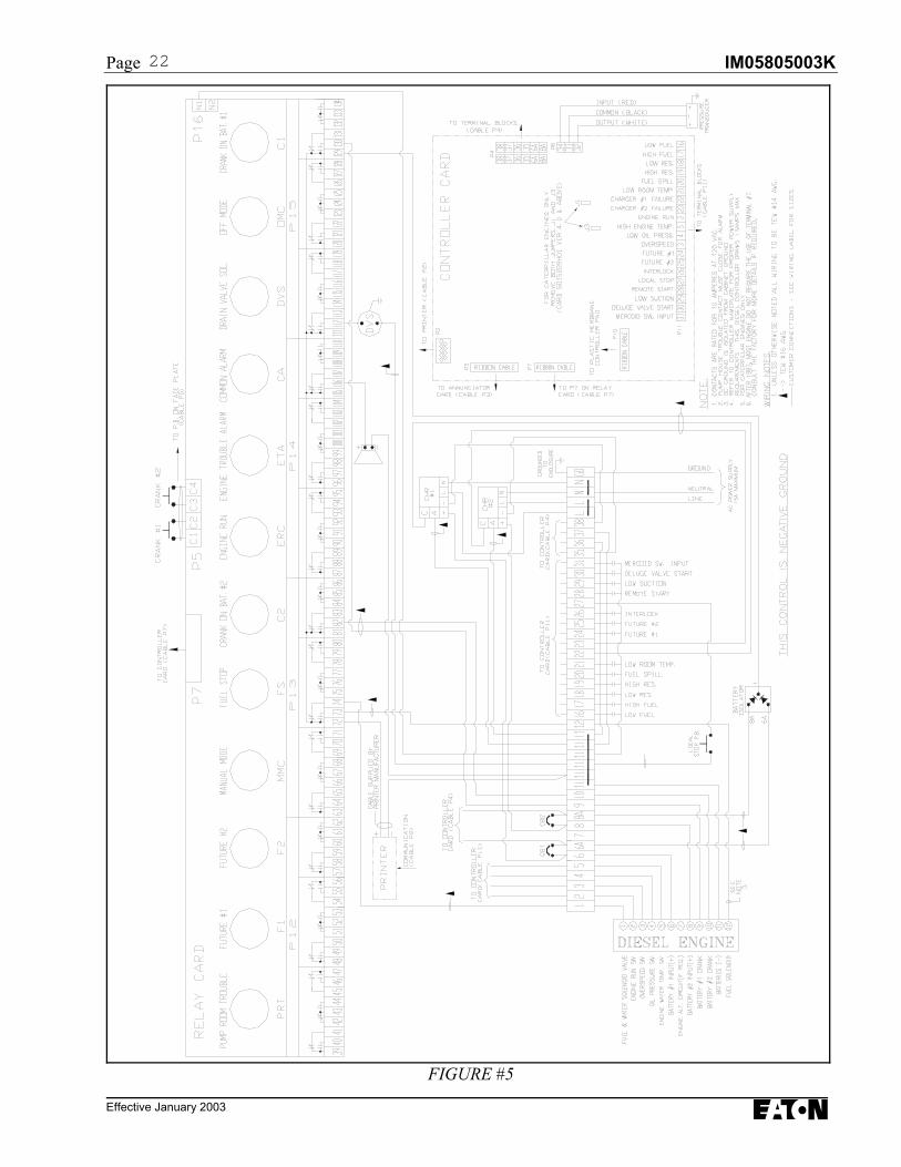
7. Alarm Signals (Annunciator Panel)Each FD100 Diesel Controller is equippedwith all the alarms as shown on page 18.Unused alarms can be activated at any time.Refer to the schematic supplied with theFD100 for alarm connections.
Refer to Appendix A: "Annunciator Alarms"affixed inside the enclosure, which describeseach alarm, method of resetting, associatedterminal reference number, common troublealarm and print out. Section 12 describes the"Print Mode".
7.1 Battery Failure
There are two annunciators on the alarmpanel for, "Battery #1 Failure" and "Battery#2 Failure". The alarm is activated duringthe cranking cycle when the controller detectsa weak or discharged battery, i.e. 67% ofrated voltage, or less, or whenever a batterycable is disconnected.
7.2 Charger Failure
There are two annunciators on the alarmpanel for, "Charger #1 Failure" and "Charger#2 Failure". The alarm is activated when thesupply power to the charger is lost or whenthe charger malfunctions (alarm contacts arefed into the controller from the chargingunit). The engine continues to run. To avoidnuisance power failures, a 20 second delay isbuilt in to the Charger Failure alarmactuation circuit.
7.3 Engine Run
This annunciator illuminates when thecontroller receives a running signal from thediesel engine.
7.4 Engine Overspeed
An "Engine Overspeed" alarm will shutdownthe engine regardless of the start condition -in all modes. The signal is sent from theengine to the controller.
7.5 Fail To Start
After 6 cranking attempts, three attempts perbattery, the "Fail To Start" annunciator willilluminate. Attention to the diesel and itsassociated equipment is requiredimmediately.
7.6 Fuel Spill*
Indicates that the relief valve has beenmanually opened. This will cause a start ofthe engine once the pressure drops below theset value.
7.7 High Engine Temperature
Indicates that the coolant temperature in thewater jackets is extremely hot. The overtemperature switch on the engine signals thecontroller. The engine continues to run in theAUTO and MANUAL modes. In the"TEST" mode and during the weekly testcycle the engine will shutdown.
7.8 Low / High Fuel **(When Fuel Level Switch Wired)
Indicates that the engine fuel supply islow / high. The engine continues to run.
7.9 Low Oil Pressure
The controller has an inherent delay tobypass the low oil pressure alarm duringengine start up. After the delay, should theengine receive a 'Low Oil Pressure' signal,the controller will initiate an alarm. Theengine will continue to run in the 'AUTO' and'MANUAL' mode. In the 'TEST' mode andduring the weekly test cycle this alarm willautomatically shutdown the engine. Thissituation will result in serious engine damageif kept running.
7.10 Low / High Reservoir
Indicates that the water reservoir level is low/ high. (Signal supplied by others)
7.11 Low Room Temperature(When Thermostat Installed)
Should a "Low Room Temperature" alarmoccur the engine will continue to run.
* Software versions before V2.91 have aRelief Valve Discharge alarm in lieu of theFuel spill alarm.
** Software versions prior to V2.91 have anaudible alarm for Low / High Fuel whichfollowed the input signal from the fuel tank.
IM05805003K Page 9
Effective January 2003
8. Battery ChargersBattery chargers are independent chargersproducing a maximum of 10 amps each atfull rate. The battery chargers are fullyelectronic and will limit the output current to10 amps even during a continued shortcircuit.
The green LED on the charger indicates thepresence of AC power.
Once the battery comes up to full charge thecharger will automatically go into a float ratemode and will provide the exact tricklecurrent required to maintain the batteriesfully charged.
The chargers are equipped with two sets ofdry, Form C contacts. One to detect lowbattery voltage, J2, (not wired) indicated witha red LED marked as LOW VOLTS, and theother to detect the loss of AC power, J3,wired to the controller.
The required charge mode can be selectedusing the 3-position toggle switch locatednear the center of the instrument panel of thecharger.
The three available modes are:
• Continuous "FLOAT"• Continuous "EQUALIZE" (not recommended for more than 12 hours)• "AUTOMATIC" (factory setting)
NOTE: It is essential that the toggle switch beleft in the automatic mode when thecontroller is not supervised.
In this mode "EQUALIZE" is automaticallyinitiated by a low battery voltage andautomatically terminated by a high batteryvoltage. This assures that the battery willreceive an "EQUALIZE" charge only whenneeded and only for the required period oftime.
The chargers have reverse polarity protectionwhich prevents the charger from starting on abattery which has been connected in reversepolarity or having a voltage below a certainminimum, as indicated by the red LED.
Two other LED's are provided to indicatewhich mode the charger is operating in,FLOAT or EQUALIZE.
Note that the two chargers are rotated 1800
from each other. A label affixed to eachcharger clearly indicates the position of the 3-position switch and the indication of the fiveLED's.
Extra care must be taken while working nearthe chargers. The chargers contain live partsand caution must be exercised with ACpower applied to the units.
NOTE: All of the charger potentiometers arefactory set and are based on therequired current charging rates, andbattery voltages. DO NOT adjust thesepotentiometers. Doing so will voidwarranty.
9. Operating TemperatureThe operating temperature range of theFD100 is: -200C to 700C.
Temperatures lower or higher than thosespecified may cause damage to the dieselengine controller.
Page 10 IM05805003K
Effective January 2003
10. Initial Start Up1. Ensure that circuit breakers CB1 and CB2 are in the OFF (0) position.
2. Ensure that AC power is supplied to terminals L and N, and GD is grounded.
3. Connect engine batteries to the controller, terminals 6,8 and 11. If batteries are connected in wrong polarity the battery voltage will read zero.
Note that terminals 6A and 8A are for factory use only and NOT for external connections.
4. The Chargers MUST be in placed in the AUTO mode (refer to toggle switch on chargers - factory set inthe AUTO mode).
5. Turn circuit breakers CB1 and CB2 ON ("1" position).
6. Turn printer ON after CB1 and/or CB2 have been turned ON.
7. Pressure (start) is factory preset at 1 PSI.
8. Place the controller in the 'OFF' mode by depressing the "OFF" button.
9. Ensure that the Diesel is programmed to user's specifications. Refer to section 6 in this manual.Refer to STATUS printout for factory set parameters.
10.1 Automatic Start Test
Test printer while in Auto mode as per Section 12 of manual.
Depress the "AUTO" button.
LED on "AUTO" button will light and Annunciator "Switch in Auto" will illuminate.
Ensure that water pressure is available and the LCD display on the Display Panelis reading the system pressure, in PSI.
Decrease water pressure. Controller will begin its cranking cycle.
Should the engine fail to start after 6 crank and rest cycles, the audible alarm will soundand the "Fail To Start" annunciator will illuminate. Depress "OFF" button to silence alarm.
When engine starts, "Engine Run" annunciator illuminates.
Increase water pressure above programmed STOP point. Press the stop pushbutton on theenclosure. If the pressure is satisfied, the engine will stop.
OR
If STOP mode is programmed for "Auto-Stop", engine will stop after Run Period Timer timesout and pressure is satisfied. RPT is programmed by the user, factory set at 30 minutes.
If Sequential Timer is > 0 seconds, automatic start will be delayed by the number of secondsprogrammed.
If AC Power Failure is ENABLED, automatic start will be delayed by the number of secondsprogrammed upon a power failure.
IM05805003K Page 11
Effective January 2003
10.2 Manual Start Test
Depress the "Manual" button. The LED on the button will illuminate.
Fuel Solenoid relay will change state.
Press Crank No.1 pushbutton. Engine cranks and starts, "Engine Run" annunciator illuminates.
Press "OFF" button. Wait for engine to stop. Push "Manual" button then press Crank No.2pushbutton. Engine cranks and starts, "Engine Run" annunciator illuminates.
Press "OFF" button. Engine will stop.
10.3 Test Start Test
Depress the "Test" button. LED on button will illuminate.
Drain Valve Solenoid will energize and reduce pressure. Controller will start engineautomatically. "Engine Run" annunciator illuminates.
Press "OFF" button. Engine will stop.
NOTE: Engine will stop if Low Oil Pressure, High Water Temp orOverspeed alarms are detected.
10.4 Weekly Exerciser Test
Depress "OFF" button.
To test the Weekly Exerciser, preprogram the controller to initiate the test at a time suitable tothe user.
Depress "AUTO" button.
At programmed time and date the drain valve solenoid will open. When the pressure drops belowthe start PSI value, engine will start, "Engine Run" annunciator will illuminate, and drain valvesolenoid will close.
Press "OFF" button. Engine will stop.
Reprogram Weekly Exerciser for normal operation.
NOTE: Engine will stop if Low Oil Pressure, High Water Temp orOverspeed alarms are detected.
Page 12 IM05805003K
Effective January 2003
11. Field Failure Alarm SimulationEnsure that CB1 and/or CB2 are in the ONposition prior to applying power to the printer(refer to nameplate above printer).
Ensure that both CB1 and CB2 are in the ONposition and that there is AC power to thechargers. Place the controller in either theAUTO or MANUAL mode.
NOTE: - For all engine alarms, the Engine Trouble Alarm relay will energize.
- Do not put an AC voltage on these contacts.
11.1 Charger Failure
Remove AC power to the diesel controller panel.After a delay of 180 seconds, the alarm willsound and both Charger #1 Failure and Charger#2 Failure indicating LED’s will display. Or,jumper 11 & 22, 11 & 23; [ 11 is Battery(negative)].
After test, reapply AC power to continue testingof other alarms. To reset alarm go to OFF modeand then back into AUTO or MANUAL mode.
11.2 Battery Failure
Turn OFF CB1. Alarm will sound and BatteryFailure #1 will indicate in the display.To reset alarm go to OFF mode and then backinto AUTO or MANUAL mode.
Turn ON CB1 and turn CB2 OFF. Alarm willsound and Battery Failure #2 will indicate in thedisplay. Reset alarms as per above.
NOTE:Do not turn off both CB1 and CB2simultaneously. Otherwise power willbe lost to the controller card.
NOTE:For the following tests, while controlleris in the AUTO or MANUAL mode,place a JUMPER between terminal 2 &11. This will give an ENGINE RUNsignal to the controller. Or, you can runthe engine.
There is an inherent 15 second delay fordetecting alarms after an ENGINE RUNsignal.
11.3 Low Oil Pressure
Jumper 4 & 11. Alarm will sound and indicateon the display. To silence alarm, controller mustbe in the OFF mode. If the engine is wired tothe panel and the engine itself is NOT running,the LOW OIL PRESSURE alarm willautomatically alarm after the 15 second delay,with terminals 2 and 11 jumpered.
11.4 High Engine Temperature
Jumper 5 & 11. Alarm will sound and indicateon display. To silence alarm, controller must bein the OFF mode. Note that the LOW OILPRESSURE alarm will also indicate if terminal4 is wired from the engine to the panel and theengine is not physically running.
11.5 Engine Fail to Start
(ALL ENGINES EXCEPT CATERPILLAR)
1. Disconnect field wires #9 & #10 on FirePump Controller & initiate automaticstart (Place controller in TEST mode).Note that actual engine will not crankthus reducing wear and tear on itsstarters and batteries.
Caterpillar Engines: Install a wirejumper between terminals 1 & 12 andinitiate automatic start.
2. Allow pressure to drop and begincranking sequence.
3. Wait 180 seconds to allow for 3 cranksper battery (15 seconds cranking, 15seconds rest, 6 times).
4. Alarm will sound and Fail To Startindicator will display. To silence alarm,place controller in the OFF mode.
11.6 Engine Overspeed
Mechanically close speed switch relay on thediesel engine or jumper 3 & 11. Alarm willsound, Engine Overspeed indicator will display,and the fuel stop relay will energize.
To silence alarm, place controller in the OFFmode.
11.7 Other Alarms (Pump Room Alarms)
To test pump room alarms, such as Low Fuel,Low Room Temp etc., place a jumper betweenterminal 11 and the corresponding alarmterminal input (refer to Appendix A affixed tocontroller door).
NOTE: The Pump Room Trouble relay will also activate.
IM05805003K Page 13
Effective January 2003
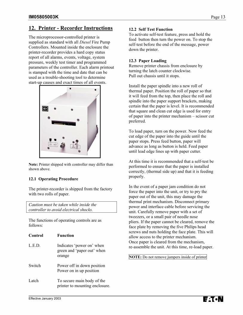
12. Printer - Recorder InstructionsThe microprocessor-controlled printer issupplied as standard with all Diesel Fire PumpControllers. Mounted inside the enclosure theprinter-recorder provides a hard copy statusreport of all alarms, events, voltage, systempressure, weekly test timer and programmedparameters of the controller. Each alarm printoutis stamped with the time and date that can beused as a trouble-shooting tool to determinestart-up causes and exact times of all events.
Note: Printer shipped with controller may differ thanshown above.
12.1 Operating Procedure
The printer-recorder is shipped from the factorywith two rolls of paper.
Caution must be taken while inside thecontroller to avoid electrical shocks.
The functions of operating controls are asfollows:
Control Function
L.E.D. Indicates ‘power on’ whengreen and ‘paper out’ whenorange
Switch Power off in down positionPower on in up position
Latch To secure main body of theprinter to mounting enclosure.
12.2 Self Test FunctionTo activate self-test feature, press and hold thefeed button then turn the power on. To stop theself-test before the end of the message, powerdown the printer.
12.3 Paper LoadingRemove printer chassis from enclosure byturning the latch counter clockwise.Pull out chassis until it stops.
Install the paper spindle into a new roll ofthermal paper. Position the roll of paper so thatit will feed from the top, then place the roll andspindle into the paper support brackets, makingcertain that the paper is level. It is recommendedthat square and clean cut edge is used for entryof paper into the printer mechanism – scissor cutpreferred.
To load paper, turn on the power. Now feed thecut edge of the paper into the guide until thepaper stops. Press feed button, paper willadvance as long as button is held. Feed paperuntil lead edge lines up with paper cutter.
At this time it is recommended that a self-test beperformed to ensure that the paper is installedcorrectly, (thermal side up) and that it is feedingproperly.
In the event of a paper jam condition do notforce the paper into the unit, or try to pry thepaper out of the unit, this may damage thethermal print mechanism. Disconnect primarypower and interface cable before servicing theunit. Carefully remove paper with a set oftweezers, or a small pair of needle nosepliers. If the paper cannot be cleared, remove theface plate by removing the five Philips headscrews and nuts holding the face plate. This willallow access to the printer mechanism.Once paper is cleared from the mechanism,re-assemble the unit. At this time, re-load paper.
NOTE: Do not remove jumpers inside of printer
Page 14 IM05805003K
Effective January 2003
12.4 Print Modes
While in the MENU mode, the 'PRINTROUTINE' can be set up for either 'Auto' or'Manual'.
12.4.1 Auto Print
Messages will print directly to the printer as theevent or alarm occurs.
*DO NOT LEAVE IN THIS MODE*
12.4.2 Manual Print
The event and alarm messages are stored inmemory until the 'Time/Print' key is depressed,at which time all stored data is printed. Thecontroller will store up to 1024 messages on aFirst In-First Out basis. To print the stored datahold the 'Time/ Print' key for 3 seconds or more.DO NOT REMOVE POWER FROM PRINTERUNTIL ALL MESSAGES ARE PRINTED,OTHERWISE INFORMATION WILL BE LOST.
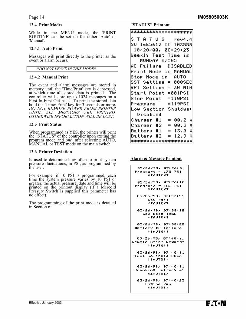
12.5 Print Status
When programmed as YES, the printer will printthe "STATUS" of the controller upon exiting theprogram mode and only after selecting AUTO,MANUAL or TEST mode on the main switch.
12.6 Printer Deviation
Is used to determine how often to print systempressure fluctuations, in PSI, as programmed bythe user.
For example, if 10 PSI is programmed, eachtime the system pressure varies by 10 PSI orgreater, the actual pressure, date and time will beprinted on the printout display (if a MercoidPressure Switch is supplied this parameter hasno effect).
The programming of the print mode is detailedin Section 6.
"STATUS" Printout
Alarm & Message Printout
IM05805003K Page 15
Effective January 2003
12.7 Replacement Paper Type
The printer-recorder uses a thermographicprinting paper on a 2-3/4” diameter roll whichis 2-1/4” wide and having a plastic core witha 7/16” hole. Suitable paper is available atmost office-supply stores. See list belowdepicting the office supply stores and theirrespective catalog number for the paper.
NOTE: If the end of the paper roll is taped, extracaution must be taken when the colored stripeappears – indicating the paper is running out. At thispoint turn the printer off and replace the roll. Notethat one or two messages may be lost as a result.
NON-TAPED ENDED ROLLS
WILSONS: LAB CR722
TAPED ENDED ROLLS
STAPLES: 14485GRAND & TOY: 7767000OFFICE DEPOT: 302-232
Page 16 IM05805003K
Effective January 2003
FIGURE #1
IM05805003K Page 17
Effective January 2003
FIGURE #2
Page IM05805003K18
Effective January 2003
APPENDIX A : ANNUNCIATOR ALARMS
IM05805003K Page 19
Effective January 2003
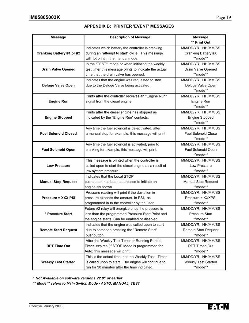
APPENDIX B: PRINTER 'EVENT' MESSAGES
Message Description of Message Message** Print Out
Indicates which battery the controller is cranking MM/DD/YR, HH/MM/SSCranking Battery #1 or #2 during an "attempt to start" cycle. This message Cranking Battery #X
will not print in the manual mode. **mode** In the "TEST" mode or when initiating the weekly MM/DD/YR, HH/MM/SS
Drain Valve Opened test timer this message prints to indicate the actual Drain Valve Opened time that the drain valve has opened. **mode** Indicates that the engine was requested to start MM/DD/YR, HH/MM/SS
Deluge Valve Open due to the Deluge Valve being activated. Deluge Valve Open**mode**
Prints after the controller receives an "Engine Run" MM/DD/YR, HH/MM/SSEngine Run signal from the diesel engine. Engine Run
**mode** Prints after the diesel engine has stopped as MM/DD/YR, HH/MM/SS
Engine Stopped indicated by the "Engine Run" contacts. Engine Stopped**mode**
Any time the fuel solenoid is de-activated, after MM/DD/YR, HH/MM/SSFuel Solenoid Closed a manual stop for example, this message will print. Fuel Solenoid Close
**mode** Any time the fuel solenoid is activated, prior to MM/DD/YR, HH/MM/SS
Fuel Solenoid Open cranking for example, this message will print. Fuel Solenoid Open**mode**
This message is printed when the controller is MM/DD/YR, HH/MM/SSLow Pressure called upon to start the diesel engine as a result of Low Pressure
low system pressure. **mode** Indicates that the Local STOP MM/DD/YR, HH/MM/SS
Manual Stop Request pushbutton has been depressed to initiate an Manual Stop Requestengine shutdown. **mode** Pressure reading will print if the deviation in MM/DD/YR, HH/MM/SS
Pressure = XXX PSI pressure exceeds the amount, in PSI, as Pressure = XXXPSIprogrammed in to the controller by the user. **mode**
Future #2 relay will energize once the pressure is MM/DD/YR, HH/MM/SS* Pressure Start less than the programmed Pressure Start Point and Pressure Start
the engine starts. Can be enabled or disabled. **mode** Indicates that the engine was called upon to start MM/DD/YR, HH/MM/SS
Remote Start Request due to someone pressing the "Remote Start" Remote Start Request pushbutton. **mode** After the Weekly Test Timer or Running Period MM/DD/YR, HH/MM/SS
RPT Time Out Timer expires (if STOP Mode is programmed for RPT Timed OutAuto) this message will print. **mode** This is the actual time that the Weekly Test Timer MM/DD/YR, HH/MM/SS
Weekly Test Started is called upon to start. The engine will continue to Weekly Test Started run for 30 minutes after the time indicated. **mode**
* Not Available on software versions V2.91 or earlier** Mode ** refers to Main Switch Mode - AUTO, MANUAL, TEST
Page IM05805003K20
Effective January 2003
FIGURE #3
IM05805003K Page 21
Effective January 2003
FIGURE #4
Page IM05805003K22
Effective January 2003
FIGURE #5

IM05805003K Page 23
Effective January 2003

EATON
Cutler-Hammer403 East Lake Blvd., Airdrie, Alberta, T4A 2G1Canadatel: 403-948-7955fax: 403-948-6967www.chfire.com
© 2003 Eaton CorporationAll Rights ReservedPrinted in CanadaPublication No.: IM05805003KJanuary 2003