Embed Size (px)
Citation preview

(
Types: o
INSTRUCTIONS AND RECOMMENDED PARTS FOR MAINTENANCE
POWERNAC* VACUUM CIRCUIT BREAKER WITH ML-17 MECHANISM
• VB-4.16-250-3000A-78-0, -1, -2, -3
VB-4.16-350-1200A-78-0, -1, -2, -3 VB-4.16-350-2000A-78-0, -1, -2, -3. VB-4.16-350-3000A-78-0, -1, -2, -3
VB-7.2-500-1200A-66-0, -1, -2, -3 ,, VB-7.2-500-2000A-66-0, -1, -2, -3 VB-7.2-500-3000A-78-0, -1, -2, -3
VB-13.8-500-3000A-58-0, -1, -2, -3
VB-13.8-750-1200A-58-0, -1, -2, -3 VB- l3.8-750-2000A-58-0, -1, -2, -3 VB-l3.8-750-3000A-78-0, -1, -2, -3
VB-13.8-1000-1200A-77-0, -1, -2, -3 VB-13.8-1000-2000A-77-0, -1, -2, -3 VB-13.8-I000-3000A-77-0, -I, -2, -3
0 Vacuum Breaker - Nominal Voltage - Nominal MVA -Continuous Current - Close and Latch Kiloamperes - Model Designator (No number on breaker nameplate indicates -0 Model)
GENERAL fj ELECTRIC
GEK-90208

ILLUSTRATIONS
Figure No. Page No.
l. Power/ Vac• Breaker- Front View........... . ............................................... 7 2. Front View of Power/ Vac•Breaker Without Front Cover.............................. .. ......... 7 3. Toggle Linkage Positions of ML-17 Mechanism - View from Rear . . . . . . . . . . . . . . . . . . . . . . . . . . . . . . . . 9 4. Exploded Schematic - Rear View ML-17 Mechanism
a. --0,-1 ModelDesignations ........................................................... 10-11 b. -2,-3 Model Designations ...................................... .. ................... 12-13
5. Typical Wiring Diagram for ML-17 Mechanism .......................... . ................... . .. 14 6. Rear View of Power/ Vac• Breaker Showing Rating Interference Plate . . . . . . . . . . . . . . . . . . . . . . . . . . . . . . 15 7. Rating Interference Plate 1200 / 2000A Breaker. . . . . . . . . . . . . . . . . . . . . . . . . . . . . . . . . . . . . . . . . . . . . . . . . . 15 8. Power/ Vac• Breaker- Right Side View ....................................................... 15 9. Power/ Vac• Breaker - Left Side View ........................................................ 16
10. Closing Spring Gag Interlock ................................................................ 16 11. Slow Close Pin on Flywheel . . . . . . . . . . . . . . . . . . . . . . . . . . . . . . . . . . . . . . . . . . . . . . . . . . . . . . . . . . . . . . . . . 18 12. Primary Contact Gap and Erosion Indication . . . . . . . . . . . . . . . . . . . . . . . . . . . . . . . . . . . . . . . . . . . . . . . . . . . 19 13. Wipe Gauge ........................................................ .. .................... 20 14. Control Switches .................................................. . ............. .. ........ 21
·I
2

(
I. 1.1 1.2 1.2. l 1.2.2
2. 2.1 2.2 2.3
3. 3.1 3.2 3.3 3.4 3.5 3.6 3.7 3.7.l 3.7.2 3.7.3 3.7.4 3.7.5
4. 4.1 4.2 4.3 4.4 4.5
5. 5.1 5.2 5.3 5.4 5.5 5.6 5.6.l 5.6.2 5.6.3 5.7 5.8 5.8.l 5.8.2 5.9
CONTENTS
Introduction ................... . ......... . .............................. . .... . ....... . Scope ............... . ............ . ................................. . .............. . Safety .................. . .......................................................... .
General ............................................................... .. . . ....... . Specific . ............ . ......................... . .................................. .
Receiving, Handling and Storage ........................ . .. .. ................... . ....... . Receiving ............................... . .......................................... . Handling .......................................................................... . Storage ........................................................................ . ... .
Description and Principles of Operation ................................................... . General ............................................................................ . Close Spring Charging ........................................................ .. ..... . Closing Operation ..... ............ ........ . ................. . .. . ...... ..... ......... . Opening Operation .................................................................. . Trip Free Operation ................................................................. . Control Circuit ..................................................................... . Interlocks ... . ..... . ................................................................ .
Rating Interference Plate .... ... . ..... . ................... . ............ .. ........... . Closing Spring Discharge Interlock ...................................... .. .. . .. . .... . . Negative Trip Interlock .......................................... . ... . .. . .. .... ..... . Positive Interlock .............................................................. . .. . Closing Spring Gag Interlock ........................................................ .
Preinstallation Checkout ............................................................... . General . . ............................ . ............ . ..... . ... . .. . ................... . Safety Precautions .................................................................. . Shipping Position ........................................................... . ....... . Mechanical Operation ............................................................... . Electrical Checks .................................................................... .
Mechanical Checks and Adjustments ..................................................... . General ............................................................................ . Slow Closing Operation .............................................................. . Pull Rod Adjustment ................................................................ . Trip Latch Clearance ................................................................ . Overtravel Stop Bolts . . .. ...... .. .... .................. .. ..... .. .. . .. .. .............. . Wipe and Gap Adjustments ........................................................... .
General ............... ..... ....... . ....................... . .......... .... ........ . Checking ............................................................... . .. .. .... . Adjustment ............................................................. . ........ .
Primary Contact Erosion Indication .................................................. . . . Control Coil Plunger T ravel ........................................................... .
Trip Coil ....................................................................... . . . Close Coil ........................................................................ .
Control Switches ........................................................ . ........... .
5 5 5 5 5
6 6 6 6
6 6 7 8 8 8 8 8 8
15 16 16 16
17 17 17 17 17 17
18 18 18 18 19 19 19 19 20 20 21 21 21 21 21
3

4
6. 6.1 6.2 6.3 6.4 6.4.1 6.4.2 6.5 6.6
7. 7.1 7.2 7.3 7.4 7.5
Electrical Checks . . ....... ..... .............................................. ....... . . . . Control Power ...................................................................... . Timing ............................................................................ . Megger . . . ............................................................. . .. . .. . ..... . High-Potential Test ............... . ...................................... .......... .. .
Primary Circuit ................................................................... . Secondary Circuit .. . . . .......... ................. ........... .......... ...... . ..... .
Vacuum Interrupter Integrity Test .... ..... .... ...... .... . ...... ............ ...... . .... . . Primary Circuit Resistance .......... ................ ............ .......... ........... . .
Maintenance .................................... . .. ..... . . ........................... . General ............................................................................ . Service Conditions .................................................................. . Fault Interruptions .................................................................. . Recommended Maintenance .......................................................... . Lubrication ........................................................................ .
APPENDIX A Recommended Spare Parts and repair Procedures
22 22 22 22 22 22 22 22 22
23 23 23 23 23 24
25
. '

POWERNAC* VACUUM CIRCUIT BREAKER WITH ML-17 MECHANISM
TYPES VB-4.16-250,-350 VB-7.2-500 VB-13.8-500, -750, -1000
1. INTRODUCTION
I.I SCOPE
This manual provides information needed by the user to properly check out, install and maintain the Power/ Vac• breaker.
Appendix A provides a list of recommended spare parts for the Power I Vac* breaker and instructions for installation and repair.
Appendix B provides instructions for check out and maintenance of breakers equipped with a Direct Acting Undervoltage Trip Device.
The Power/ Vac• vacuum circuit breaker is a horizontal drawout, removable and interchangeable interrupting element for use in metalclad switchgear to provide protection and control of electrical apparatus and power systems. To the extent required applicable ANSI, IEEE and NEMA Standards are met. No such assurances are given with respect to local codes and ordinances as they vary greatly.
The Power/ Vac• circuit breakers are available in continuous current ratings of 1200, 2000 and 3000 amperes in accordance with industry standards. Non-standard close and latch ratings, as shown on the front cover of this manual, are available. Combination 1200/ 2000 ampere breakers are also available. Refer to the breaker nameplate for complete rating information.
1.2 SAFETY
Each user has the responsibility to instruct all personnel associated with this equipment on all safety precautions which must be observed. The following are recommendations to be considered in a user's safety program. These recommendations are not intended to supplant the user's responsibility for devising a complete safety program and shall not be considered as such. They are rather suggestions to cover the more important aspects of personnel safety related to circuit breakers. General Electric neither condones nor assumes any responsibility for user practices which deviate from these recommendations.
1.2.1 GENERAL
I. All personnel associated with installation, operation, and maintenance of power circuit breakers should be thoroughly instructed and supervised regarding power equipment in general and, also, the particular model of equipment with which they are working. Instruction books should be closely studied and followed.
2. Maintenance programs must be well planned and carried out consistent with both customer experience and manufacturer's recommendations. Good maintenance is essential to breaker reliability and safety.
Local environment and breaker application must be considered in such programs, including such variables as ambient temperatures, actual continuous current, number of operations, type of interrupting duty, and any unusual local condition such as corrosive atmosphere or vermin problems.
1.2.2 SPECIFIC
I. DO NOT WORK ON AN ENERGIZED BREAKER. IF WORK HAS TO BE PERFORMED ON THE BREAKER, TAKE IT OUT OF SER VICE AND REMOVE IT FROM THE MET ALCLAD.
2. DO NOT WORK ON ANY PARTOFTHEBREAKER WITH THE TEST COUPLER ENGAGED.
3. All spring-charged mechanisms related to a breaker must be serviced only by skilled and knowledgeable personnel capable of gagging or releasing each spring load in a controlled manner. PARTICULAR CARE MUST BE EXERCISED TO KEEP PERSONNEL CLEAR OF MECH ANISMS WHICH ARE TO BE OPERATED OR RELEASED. Information on construction of such mechanisms is provided in this instruction book.
4. Operational tests and checks should be made on a breaker after maintenance, before it is returned to service, to ensure that it is capable of operating properly. The extent of such tests and checks should be consistent with the level of maintenance performed.
These instructions do not purport to cover all details or variations in equipment nor to provide for every possible contingency to be met in connection with installa1ion. opera1ion or maintenance. Should further informa1ion be desired or should particular problems arise which are not covered sufficiently for 1he purchaser's purposes. the molter should be referred to the General Electric Company.
• ·Registered Trademark of General Electric Company.
5

5. If maintenance on the Power/ Vac* breaker is being performed to an extended schedule such as on a 5 year or 10 year basis, it is recommended that the vacuum interrupter integrity test of paragraph 6.5 be performed each time the breaker is removed from the metalclad switchgear for reasons other than scheduled breaker maintenance if it has been more than one year since the last vacuum interrupter integrity test.
6. Interlocks are provided for the safety of the operator and correct operation of the breaker. If an interlock does
not function as described DO NOT MAKE ANY ADJUSTMENT OR FORCE THE DEVICE INTO POSITION; CONTACT THE NEAREST GENERAL ELECTRIC COMPANY INSTALLATION AND SERVICE OFFICE _,..FOR INSTRUCTIONS.
7. For breakers equipped with a Direct Acting Undervoltage Trip Device REFER TO APPENDIX "B., PRIOR TO PERFORMING Initial Checkout, Maintenance, or Repair.
2. RECEIVING, HANDLING AND STORAGE
2.1 RECEIVING
Each breaker is carefully inspected before shipment. Immediately upon receipt of the circuit breaker, an examination should be made for any damage sustained in transit. If injury or rough handling is evident, a damage claim should be filed immediately with the transportation company and the nearest General Electric Sales Office should be notified.
It is expected that due care will be exercised during the unpacking and installation of the breaker so that no damage will occur from careless or rough handling, or from exposure to moisture or dirt.
2.2 HANDLING
When lifting the breaker, use of the specially designed lift truck is recommended. It is necessary to use the truck when placing a breaker into or removing it from the metalclad switchgear. If it is necessary to lift the breaker with a hoist use four ~ inch diameter hooks rated at least 500 pounds each. Lifting locations are provided in the side frame members. Use a spreader wider than the breaker to prevent slings from contacting the interrupter supports.
A front swivel wheel and two rear wheels are provided for ease of movement on flat, level floors.
2.3 STORAGE
It is recommended that the breaker be put immediately in its permanent location. If this is not possible, the following precautions must be taken to assure the proper storage of the breaker:
1. The breaker should be protected against condensation, preferably by storing it in a warm dry room of moderate temperature such as 40° - 100°F. Circuit breakers for outdoor metalclad switchgear should be stored in the equipment only when power is available and the heaters are in operation to prevent condensation.
2. The breaker should be stored in a clean location, free from corrosive gases or fumes; particular care, for example, should be taken to protect the equipment from moisture and cement dust, as this combination is present at construction sites and has a very corrosive effect on many parts.
3. Rollers, latches, etc., of the operating mechanism should be coated with 0282A2048P009 grease to prevent rusting.
If the breaker is stored for any length of time, it should be inspected periodically to see that rusting has not started and to ensure good mechanical condition. Should the breaker be stored under unfavorable atmospheric conditions, it should be cleaned and dried out before being placed in service.
3. DESCRIPTION AND PRINCIPLES OF OPERATION
3.1 GENERAL
The Power/ Vac* vacuum circuit breaker uses sealed vacuum power interrupters to establish and interrupt a primary circuit. Primary connections to the associated metalclad switchgear are made by horizontal bars and disconnect fingers, electrically and mechanically connected to the vacuum interrupters. Molded interrupter supports, one per phase on a three-phase circuit breaker, provide mount-
6
ings for the primary bars, interrupters, current transfer fingers, and heat dissipation fins (where used). The operating mechanism provides vertical motion at each phase location in order to move the lower contact of the vacuum interrupters from an open position to a spring-loaded closed position and then back to the open position on command.

Fig. I - Power/ Vac* Breaker - Front View
1 - Front cover 2 - Manual trip button 3 - Manual close button 4 - OPEN/ CLOSE indicator 5 - CHARGE/ DISCHARGE indicator 6 - Nameplate 7 - Secondary Disconnect Handle 8 - Manual Wind Shaft 9 - Rackout Arm
The ML-17 mechanism is of the stored-energy type and uses a gearmotor to charge a closing spring. During a closing operation, the energy stored in the closing spring is used to close the vacuum interrupter contacts, compress the wipe springs which load the contacts, charge the opening spring, and overcome bearing and other friction forces. The energy then stored in the wipe springs and opening spring will open the contacts during an opening operation.
Closing and opening operations are controlled electrically by the metalclad switchgear or remote relaying. Mechanical control is provided by manual close and trip buttons on the circuit breaker. The closing spring may be manually charged, and a method for slow-closing the primary contacts is available. The mechanism will operate at the a-c or d-c voltage indicated on the circuit breaker nameplate.
Mechanical and electrical interlocks are provided arid are described in PARAGRAPH 3.7, INTERLOCKS.
3.2 CLOSE SPRING CHARGING
Figure 4 shows the mechanism expanded schematically with the primary contacts open and the closing spring nearly charged. When the closing spring is discharged, the AA flywheel eccentric will be about 180 degrees from where it is shown with respect to center pivot CC. The transfer crank (14) will be rotated counterclockwise, the slotted link (17)
Fig. 2 Front View of Power/ Vac• Breaker Without Cover
I - Upper Interrupter Connection 2 - Interrupter Support 3 - Operating Rod 4 - Rackout Arm 5 - Rollers for Track 6 - Manual Trip Button 7 - Open-Close Indicator 8 - Counter 9 - Spring Charge Indicator
10 - Manual Wind Shaft 11 - Manual Close Button 12 - Handle to Connect Secondary
Disconnects in Test Position
will be holding the close toggle (20, 21) against the frame through link (19), and the trip latch (18) will be held out of engagement clockwise by the trip toggle roller (52). The toggle linkage will appear as shown in Fig. 3(d). When the closing spring is discharged, switch operator (44), operates the motor limit switch (43). If the close-latch-checking switch (5) is made and power is available, the gearmotor ( 45) will drive the wind hub (11) counterclockwise. Slow-close pawl (IO) will be held out of possible engagement with the wind hub notch by the action of the slow-close pin (48).
After some rotation of the wind hub ( 11) at no load, its notch engages the wind pawl (9) and rotates the flywheel counterclockwise, compressing _ the close spring assembly (6), and rotating the transfer crank (BB) shaft clockwise by pushing on rod (13). As the line of action of the close spring shifts over-center on the flywheel and attempts to discharge, the close roller (3) is blocked by the close latch ( 4) and held until a closing operation is required. Additionally, as the close spring goes over-center, the switch operator (44) is spring biased into a notch on the front flywheel (2). Arm ( 40) moves clockwise which, through the action of the rod ( 41) causes a flag (42) to indicate "CHARGE". A cam (12) engages the wind pawl (9), moving it from contact with the hub ( 11) notch, thereby allowing the gearmotor to coast to a stop when power is removed by limit switch (43).
As the close spring is compressed, the slotted link ( 17) rises, and the close toggle (20, 21) forms a more acute angle
7

until the closing spring goes over-center and the trip latch (18), is spring biased into place under the trip roller. When the trip latch is in place, the latch-checking switch (47) closes.
With the close spring charged and the breaker open the toggle linkage is as shown in Fig. 3(a).
If control power is lost, or manual operation desired, the close spring may be manually charged by using a 1's inch hex socket ratchet-type wrench to rotate the manual charging wind shaft, (8) Fig. l, in the direction indicated by the arrow until the yellow indicator shows "CHARGED".
3.3 CLOSING OPERATION (REFER TO FIG. 4)
By either energizing the close solenoid or depressing the manual close button, the close latch (4) is rotated counterclockwise and releases the close roller (3) permitting the flywheel (I, 2) to rotate counterclockwise by the force of the close spring. This action, transmitted to the slotted link ( 17) by means of the pull rod (13), transfer crank (14, 16), pulls the close toggle (20, 21) through the center against link ( 19) which is tied to the frame. This action rotates the output crank (22) counterclockwise. The Pole I bellcranks (23), on the same shaft as the output crank, also rotate counterclockwise, and by means of the horizontal connecting bar (28), rotate Pole 2 and 3 bellcranks. This rotation compresses the opening spring (29), closes the vacuum interrupters connected with each operating rod (25), and compresses the wipe spring (26) on each pole when the trunnion (24) continues moving after the operating rod (25) stops. Rotation of an arm (34) coupled to the output shaft (DD) changes the auxiliary switch (37) position, and the position flag (38) indicates "CLOSED". The lever (44) is moved out of the notch in the flywheel (2) and, with the close latch (4) in position to catch the close roller, the limit switch (43) energizes the gearmotor as described under CLOSE SPRING CHARGING. With the breaker closed, closing spring discharged, the toggle linkage appears as shown in Fig. 3(b). With the circuit breaker in the closed position, the links ( 17) can move up past the close toggle without disturbing it as they are slotted to accommodate a close spring charging in the breaker-dosed position. With the close spring charged, breaker closed, the toggle linkage appears as shown in Fig. 3(c).
3.4 OPENING OPERATION (REFER TO FIG. 4)
By either energizing the trip solenoid or depressing the manual trip button, the trip latch (18) is rotated clockwise permitting the trip toggle (19, 20) to collapse and the vacuum interrupter contacts to open under the force of the wipe springs (26) and opening spring (29). At the end of the opening stroke, a stop block (30) on the bottom of the trunnion (24) strikes set screws in the horizontal connecting bar (28) which limits the over-travel. At the same time an opening stop is provided by a plate and buffer assembly (50). An opening dash pot (31) controls opening velocity and prevents excessive rebound of the interrupter contacts. Rotation of the output shaft (DD) from a closed to an open position operates the auxiliary switch (37) as described under CLOSING OPERATION and interrupts the trip coil circuit. If the closing spring is charged, the close toggle (20, 21) can raise
8
to the top of the slotted link ( 17), thereby permitting the trip toggle to reset and the trip latch to fall in place under its roller preparatory to a closing operation. If the closing spring is not charged, the trip latch is held rotated clockwise r""until the close spring is compressed as described in CLOSE ·i SPRING CHARGING. Electrically initiated closing is . . blocked by the latch checking switch(47) when the trip latch is not reset.
3.5 TRIP-FREE OPERATION (REFER TO FIG. 4)
The linkage (19, 20, 21) is mechanically trip free in any location on the closing stroke. This means that energization of the trip coil while closing after the auxiliary switch contacts change position will rotate the trip latch (18) clockwise and permit the circuit breaker to open. The linkage will reset as in a normal open operation, the flywheel will complete its rotation, and the closing spring will recharge as described under SPRING CHARGING.
3.6 CONTROL CIRCUIT
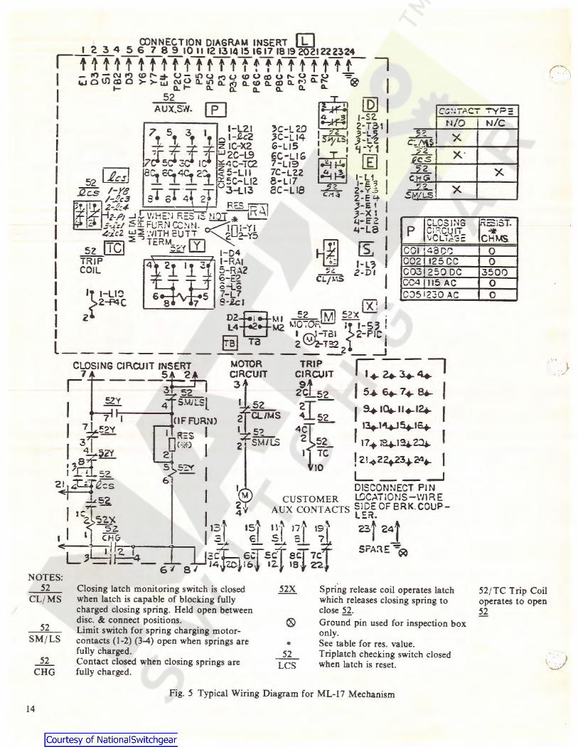
A typical Power/ Vac* circuit breaker ML-17 mechanism wiring diagram is shown in Fig. 5. Check the wiring diagram supplied with the actual circuit breaker for its wiring.
The close spring-charging-motor circuit is established through the 52 CL/ MS (close latch monitor switch) switch if the close latch is reset and the 52 SM/ LS (spring motor limit switch) if the closing spring is discharged. When the closing spring is charged, the 52 SM/ LS interrupts the circuit.
The close circuit is established through two normally · · _ . ..:,· closed relay (anti pump) contacts, 52Y, and the latchchecking switch 52/ LCS, if the trip latch is reset. An auxil-iary switch "b" contact is also in series with the close coil. The "b" contact closes when the breaker is open and opens when the breaker is closed. During a close operation, flywheel rotation closes the 52 SM/ LS contact, picking up the 52Y relay coil thereby opening the normally closed contacts to open the close coil circuit and seal the close signal in through the 52Y relay normally open contact. The sealing prevents reclosing on a sustained close command as the close signal must be removed to drop out the 52,Y relay, and reestablish the close circuit, thereby providing an anti-pump feature.
Circuit breaker mounted auxiliary switch contacts not used in the control circuit are brought out for control and indication functions. The metalclad equipment may provide a breaker operated stationary auxiliary switch for additional contacts (3, 6 or IO stages are available).
3.7 INTERLOCKS
Each Power/ Vac• vacuum circuit breaker is provided with the following interlocks:
3.7.l RATING INTERFERENCE PLATE
The rating interference plate, (Fig. 6) permits only a breaker of the matching continuous current, voltage and 'c_/
interrupting MY A rating to be inserted into a metalclad breaker compartment.

The 1200 / 2000 Ampere breaker can be used in either a 1200 or a 2000 ampere compartment. The rating interference plate must be adjusted to match the current rating of the compartment. This is done by positioning the outer
interference plate so that the edge lines up with the desired current indicated on the label attached to the breaker just above the rating interference plate. Refer to Fig. 7.
(b) Breaker Closed-Close Spring Discharged
10
3 4
0 0
0
0 0
0
(c) Breaker ClosedClose Spring Charged
10
(a) Breaker Open-Close Spring Charged
(d) Breaker Open-Close Spring Discharged
10
Fig. 3 Toggle Linkage Positions of ML 17 Mechanism View From Rear
I - Output Crank 2 - Link-Output Crank to Close Toggle 3 - Link-Close Toggle to Trip Toggle 4 - Link Trip Toggle to Frame 5 - Trip Latch
6 - Slotted Link 7 - Transfer Crank 8 - Trip Roller 9 - Linkage Return Spring
IO - Toggle Pin
9

-0
5~
33
1·1 I ·,t
4 5
46
0
(. -
' ~ ~I>. '·~ '· ... >" 39
/ 11
0 ·- ~ · ' \ ~~'\ . '
;~ ®. ~ l -- 12 •
', 0, :./) 5 __ ___
0
24
,,.30 _ 21
38
3 4
51 50
16 B- -
4 7
19
54
49~
t I
·)

~49 44
c--32 0 ~, __ / __ 10
0 . .
48 _.... ,...0 .. :'. ~ I ,. · · -'-·--o --- ----ro1.ub ' @) -11'!\ I :i. -J 0
9 \ <!>- . . -A? . '\. ,. G . '-. 0 "---~-- · '-2 -----u_.r
43 c- - ---- a
4 ·-.......... ,
/ '\)
Q Q <Z> -- A
0 n ·d': \...__, . ___ ,
Q
/
i
Q
()-
-----
6 I
13 \
I : =- -· --:;:..:.===-=-·
15
AA Eccentric shaft connecting flywheel halves BB Hex shaft connecting Transfer cranks
Fig. 4a Exploded Schematic - Rear View ML-17 Mechanism For Model Designators --0 and -1
CC Flywheel rotation axis DD Hex shaft connecting Output cranks
1 Rear Flywheel Section 19 Link - Trip Toggle to Frame 37 Auxiliary Switch - SB-12 - Four Stage 2 Front Flywheel Section 20 Link from Close Toggle to Trip Toggle 38 Position Indicator Flag 3 Close Roller 21 Link from Output Crank to Close Toggle 39 Operation Counter 4 Close Latch 22 Output Crank 40 Spring Charge Indicator Arm 5 Close Latch Monitor Switch 23 Pole 1 Bell Cranks 41 Rod 6 Closing Spring Assembly 24 Wipe Spring Trunnion Block 42 Spring Charge-Discharge Indicator Flag 7 Blocking Pin in Closing Spring Assembly 25 Interrupter Operating Rod Connection 43 Spring Motor Limit Switch 8 Hex Shaft with Connection Blocks on Flywheel 26 Wipe Spring 44 Gear Motor Limit Switch Operator 9 Wind Pawl 27 Overtravel Stop Adjustment - on Each Pole 45 Gearmotor
10 Slow Close Pawl 28 Horizontal Connecting Bar 46 Gearmotor Housing 11 Wind Hub 29 Opening Spring Assembly 47 Trip Latch Checking Switch 12 Pawl Disengagement Cam Surface - on Frame 30 Opening Stop Block 48 Slow Close Pin 13 Pull Rod 31 Dash pot 49 Retaining Clamp 14 Adjustable Throw Transfer Crank 32 Brake 50 Opening Stop 15 Adjustment Link (Factory Adjustment Only) 33 Closing Latch Shaft 51 Toggle Pin 16 Short Transfer Crank 34 Auxiliary Switch Drive Arm 52 Trip Roller 17 Slotted Link 35 Idler Link 53 Horizontal Bar Stop Locking Nut 18 Trip Latch 36 Switch Drive Arm 54 Trip Shaft

-N
41
==1.
5~
'I,~) I ' I =1 0 ,j
., '
45
42
33
c--
~1 1,
ffi 1~
39
38 37
36 - 1 ~~I
0 34
54
Dl 51 50
119 49"
18
22 .. ) 16
·-/

w
GiJ .49
~ 44
4
' '
' '
<:>
.----c--i :--a
I
t . r,>.~ -(} ~ ~ r-- . · ··r o ,,, ,0
~' --&-~A \. \ . \ . k · - •' , - •
~ j ,' '1 \ ,
: ... _.... . / \
' -<;> \,, ¢>- ,'
~-- - -
15 32
13
_j
6
~7
-~
AA Eccentric shaft connecting flywheel halves BB Hex shaft connecting T ransfer cranks CC Flywheel rotation axis
Fig. 4b Exploded Schematic - Rear View ML-17 Mechanism
For Model Designators -2 and -3
DD Hex shaft connecting Output cranks
I Rear Flywheel Section 2 Front Flywheel Section 3 Close Roller 4 Close Latch 5 6 7 8 9
10 11 12 13 14 15 16 17 18
Close Latch Monitor Switch Closing Spring Assembly Blocking Pin in Closing Spring Assembly Hex Shaft with Connection Blocks on Flywheel Wind Pawl Slow C lose Pawl Wind Hub Pawl Disengagement Cam Surface - on Frame Pull Rod Adjustable Throw Transfer Crank Adjustment Link (Factory Adjustment Only) Short Transfer Crank Slotted Link Trip Latch
19 Link - Trip Toggle t6 Frame 20 Link from Close Toggle to Trip Toggle 21 Link from Output Crank to Close Toggle 22 Output Crank 23 Pole I Bell Cranks 24 Wipe Spring Trunnion Block 25 Interrupter Operating Rod Connection 26 Wipe Spring 27 Overtravel Stop Adjustment - on Each Pole 28 Horizonta l Connecting Bar 29 Opening Spring Assembly 30 Opening Stop Block 31 Dashpot 32 Brake (not installed on -3 model designator) 33 Closing Latch Shaft 34 Auxiliary Switch Drive Arm 35 Idler Link 36 Switch Drive Arm
37 Auxiliary Switch - SB-12 - Four Stage 38 Position Indicator Flag 39 Operation C ounter 40 Spring Charge Indicator Arm 41 Rod 42 Spring Charge-Discharge Indicator Flag 43 Spring Motor Limit Switch 44 Gear M otor Limit Switch Operator 45 Gearmotor 46 Gearmotor Housing 47 Trip Latch Checking Switch 48 Slow Close Pin 49 Retaining C lamp 50 Openi ng Stop 51 T oggle Pin 52 Trip Roller 53 Horizonta l Bar Stop Locking Nut 54 Trip Shaft
• (l)NNECTION OIAGR,6M INSERT liJ I 2 3 4 5 6 7 8 9 10 1112 131415 1617 1819 2021222324
IT1T1TtTtTfttTtTfTttft ttt- I I -~-N~~~~o-~o~ocoo~u~o-o ~
wo\fla>o >->-w NOO..lllo..i<J o..coo..coo..""a.>o..:: ® I I
t- 0.. .... 0.. 0:. 0.. 0.. 52
I AUX.SW. [EJ [Q] I 1-SZ. 2-T31
I / I ~-L.2 I 1 s;.i1a.s, J-!..2 I
CC~JIACT -r"YPE
I l-L21 'C-l2.0 7T ST 3f If 0 1-£c2 )C-Ll4
I + j~ J z IC-X2 6-LJS I 'r ' ' w2c-L9 eC-LIG
C.-5 - I ~4C-TC2 7-Lt9
I r;;-t re. €C.4c. 21"1 ~5-Lll 7C-L'22 52 ~ l. l .J.. 55C-Ll2 8-L17
I .12c.s 1-re ~T ~TMJ. ;-r 3-t.13 ac-Lra
m/-...1~3 ~ 0 4 2 ...,,.._ 2.tJ,4 '"'0 'R t.\I I 2:P1 _iJ: V:HE:'i R=:s is llQJ-;--"~
I $-..l.'&I 6'1...FURNC.C>iN. ~fol-YI 4-)cZ ~~ '.'llTH EUTT I ~ '.:l-yS
I sz (IQ] TERM~ IYJ 1-04-
1 TRIP 4 21 11 "l 1-RAI COIL ~ 5-RAZ
6-E2 I , o-L~
I I 't-Y 1
~ rEJ I ~1-U -2.L 1-E .1 I Ci1- z.y ~
~ 2-E '+ ,_5, I ;-x 1 14-EZ I 't-La
Es: I f-L3 I Z·DI l
'}I-LI~ 5 7-L 7 I 2~C 8·.lc I CK! I I 2 D2eMI =2 [Ml 52X ·
L4 M2 t..10:0F. 1~ r-s~ I I ~ Ta ~@;~~212-PIC l L _______________ _J
N/O ., x lS
~2 x· .R_CS 2
H(; r.? x MILS
p CLOSING C1 Rq.~1T \/Cli.i=Gi:
COi 1 48D~ 002 125CC 003 ?50 DC 004 115 AC CJ5 1230 AC
;~r~ CIROJl~r~t I ~~~:rr ii:;T : ~: ::~:: : I ~v 4 swr.si. ~1Ms ~Isi I s.ia.u.,.i4- I I 7L~~y l I (~~IN) 5~ 421,- I ·~·.4\+J~IE4- l I
3~1 Oh·~) I SM/LS 52 11.., 141424 4 ~".lV 2 2 I TC I I .s+ "
10 1 21.q,2423.,._24,.._ ifuc:.? 5 5~ I I
~ 6 L---__J 2.!.1J:..q'25r:.~s I t DISCONNECT PIN ~:::s M CUSTOMER LOCATIONS-\'llRE
2'f AUX CONTACTS SJDECF8RK.COUP-J tC2 52}' I 4 LER.
I , ,sH~ •;'t is"! ~'j >~~I 19''1 23j z4f I .., I --l € ~ - 7J -"'L1~Jz. 14 I JJ~c} ~ea=-sc?t eff 7c SPA~E -~
- - - GI SI 14 zc. lo~ t2J 18} z-2. NOTES:
52 CL/ MS
Closing latch monitoring switch is closed when latch is capable of blocking fully charged closing spring. Held open between disc. & connect positions.
Spring release coil operates latch which releases closing spring to close 52.
52 SM/ LS
_g__ CHG
14
Limit switch for spring charging motorcontacts (1-2) (3-4) open when springs are fully charged. Contact closed when closing springs are fully charged.
* _g__ LCS
Ground pin used for inspection box only. See table for res. value. Triplatch checking switch closed when latch is reset.
Fig. 5 Typical Wiring Diagram for ML-17 Mechanism
NIC
x
iRSiST. ... CHMS.
0 0
3500 0 0
52/ TC Trip Coil operates to open 52
J -. -
-.,...;• )

Fig. 6 Rear View of .Power/ Vac• Breaker Showing Rating Interference Plate
I - Primary Disconnect Fingers 2 - Interrupter Support 3 - Coupling Clamp 4 - Operating Rod 5 - Secondary Disconnect Coupler 6 - Ground Shoe 7 - Rating Interference Plate
1200
2000
REAR VIEW 1200/2000 AMPS
3
2
Fig. 1 Rating Interference Plate - 1200/2000A Breaker
1 - Current Setting Indicator 2 - Rating Interference Plate 3 - Positioning Bolt
3.7.2 CLOSING SPRING DISCHARGE INTERLOCK
The function of the closing spring discharge interlock is to prevent racking into or out of metalclad a breaker with the closing spring charged. This is accomplished by a roller on the right-hand side of the mechanism, 4, Fig. 8, which contacts the racking mechanism and discharges the closing spring except if the breaker is in the "Disconnect/ Test" position or the "Connect" position in the metalclad switchgear. This interlock also opens the CL/ MS switch in the motor charging circuit to prevent charging the closing springs when the breaker is between the "Disconnect/ Test" or "Connect" position in the metalclad.
,---
1885444
Fig. 8 Power/ Vac• Breaker - Right Side View
1 - Front Cover 2 - Rackout Arm 3 - Rollers for Track 4 - Closing Spring Discharge Roller
15
3

3.7.3 NEGATIVE TRIP INTERLOCK
The function of the negative trip interlock, (5) Fig. 9, is to disengage the trip latch from the trip latch roller thereby preventing a closing operation. The interlock also opens the latch checking switch (52LCS) in the closing circuit thereby removing the close circuit power. The negative interlock is in operation while the breaker is moving between the "Disconnect/ Test" position and the .. Connect" position. A redundant Negative trip interlock, (6) Fig. 9, is a backup to the NEGATIVE TRIP INTERLOCK and provides the same function except it operates only near the connect position.
Fig. 9. Power/ Vac• Breaker - Left Side View
l - Interrupter Support 2 - Closing Spring Gag Interlock 3 - Positive Interlock Bar 4 - Trip Latch Blocking Hole 5 - Negative Interlock Roller 6 - Redundant Negative Interlock Roller
16
5
3.7.4 POSITIVE INTERLOCK
The positive interlock, (3) Fig. 9, operates to prevent the racking of a breaker that is closed. A linkage connected to the horizontal connecting bar extends a detent bar out from the side of the mechanism frame when it is in the closed position. If the closed breaker is in the "Connect" or "Disconnect/ Test" position in the metalclad the detent bar locks into the racking mechanism to prevent access to the hex section of the jack screw. The positive interlock also prevents the lift truck from picking up a closed breaker.
3.7.5 CLOSING SPRING GAG INTERLOCK
The closing spring gag interlock is provided on the breaker to prevent a breaker that has a gagged closing spring from entering the metalclad unit. This is accomplished by projecting a lever, (l) Fig. 10, out of the left side of the mechanism when the closing spring is gagged.
Fig. 10 Closing Spring Gag Interlock
1 - Close Spring Interlock Lever 2 - Blocking Hole 3 - Close Spring Blocking Pin 4 - Storage Hole 5 - Interlock Lever Return Spring
(Shown in Unblocked Position)
3
4
)
) _,,.,,

4. PREINSTALLATION CHECKOUT
4.1 GENERAL
Before the initial installation of the Power/ Vac• circuit breaker the device should be thoroughly inspected and checked for proper operation and adjustments. Each of the items on the following list should be performed:
(1) Check that the shipping bolt has been removed (see Shipping Position, Paragraph 4.3, for instructions). NOTE: Shipping bolt is not installed on breakers shipped inside the metalclad switchgear.
(2) Check the breaker nameplate to see that the breaker rating is for the intended application.
(3) Perform the inspection and mechanical checks as described in Paragraph 4.4, "Mechanical Operation".
(4) Check the breaker control wiring and the vacuum integrity of the interrupters as described in Paragraph 4.5, "Electrical Checking''.
4.2 SAFETY PRECAUTIONS
The Power/ Vac• circuit breaker uses powerful springs for energy storage. DO NOT WORK ON INTERRUPTERS OR THE MECHANISM UNLESS THE CLOSING SPRING IS EITHER DISCHARGED OR GAGGED, THE BREAKER IS OPEN OR THE TRIP LATCH LOCKING BOLT IS INSTALLED, AND ALL ELECTRICAL CONTROL POWER IS REMOVED. These precautions are to prevent accidental operation which could cause injury to someone working on the mechanism.
ANYONE WORKING ON THE CIRCUIT BREAKER SHOULD BE FAMILIAR WITH DEVICE AS DESCRIBED IN THIS INSTRUCTION BOOK AND SHOULD BE COGNIZANT OF ALL SAFETY PRECAUTIONS.
4.3 SHIPPING POSITION
The circuit breaker has been shipped in a closed position with the mechanism trip latch blocked by a bolt through the left side frame. A yellow tag identifies this bolt. (This bolt is not installed on breakers shipped inside the metalclad switchgear.) Before operation or insertion into the metalclad equipment, this bolt must be removed and the mechanism tripped open with the manual trip button. NOTE: Save
the shipping bolt (if installed) for use in locking the breaker closed for maintenance or repair. The close spring is discharged when shipped.
After removing packing material, locate, and remove (if installed) the trip latch blocking bolt indicated with a yellow tag on the left side sheet of the mechanism. Press in on the manual trip push button, (2) Fig. 1, to trip the mechanism open, keeping hands from moving parts.
Close and open springs are now in their discharged positions. Check this by first pressing the manual close button, then the manual trip push button.
4.4 MECHANICAL OPERATION
Prior to operating the mechanism check the breaker for signs of damage or loose hardware.
Perform the slow closing operation described in Paragraph 5.2.
Check the Wipe and Gap as described in Section 5.6.2 and readjust if required. Check the erosion indication as described in Section 5.7.
4.5 ELECTRICAL CHECKING
Electrical checking consists of operating the breaker electrically and performing the vacuum interrupter integrity test plus those tests required by local operating procedures.
(l) To check the electrical opera ti on use the test cabinet if provided or the test position in the metalclad switchgear. Compare the available control voltage to the voltage indicated on the breaker name plate. Close and open the breaker several times to check electrical operation.
(2) Perform a vacuum interrupter integrity test to verify the condition of the interrupters. Perform the test as described in Section 6.5.
(3) The following additional testing may be performed if desired:
a. Megger® tests per para. 6.3 b. Primary circuit high potential per para. 6.4.1 c. Secondary circuit high potential per para. 6.4.2 d. Primary circuit resistance per para. 6.6
17

5. MECHANICAL CHECKS AND ADJUSTMENTS
5.1 GENERAL
Checking the mechanical adjustments may be performed in any order. However, the adjustments associated with the stroke of the mechanism must be performed in the prescribed order since they are related in such a way that the adjustment of one affects the next in the series. These adjustments and the prescribed order are:
(1) Pull rod adjustment
(2) Trip latch clearance
(3) Overtravel stops
(4) Wipe and Gap setting
For example, if the pull rod is adjusted, then the trip latch clearance must be checked and adjusted followed by resetting the overtravel stops and then checking and adjusting the wipe and gap setting. However, if only the wipe and gap setting is adjusted, it is not necessary to perform the adjustments preceding it.
When adjusting the pull rod or the trip latch clearance, the overtravel stops should be backed out of the horizontal connecting bar two turns to assure that they do not interfere with the mechanism stroke during the adjustment.
5.2 SLOW CLOSING OPERATION
Slow closing the breaker allows observation of the motion of the mechanism while manually cranking it from the open to the closed position. The slow closing operation is required when performing adjustments on the breaker such as setting the pull rod adjustment and when setting the wipe and gap.
( 1) Manually charge the breaker closing spring using a Ys inch hex socket-ratchet-type wrench for safety, and turn in the direction of the arrow as indicated on the end of the manual wind shaft, (8) Fig. 1. Several rotations with no apparent load are necessary until the winding mechanism engages the spring-charging pawl.
As the manual charging shaft is rotated the trip latch will reset first with a small "click". Continued rotation will fully charge the closing spring and a louder sound will be heard. At this time the charge/ discharge indicator (5) Fig. 1 will change from "Discharged" to "Charged". Stop cranking when this occurs.
CAUTION
CHECK THAT THE CLOSING SPRING IS FULLY CHARGED WITH THE CLOSE ROLLER, (3) Fig. 4, RESTING AGAINST THE CLOSE LATCH, (4) Fig. 4.
(2) Insert the close spring blocking pin, (3) Fig. IO, by carefully removing it from its storage hole, rotating the interlock lever and inserting it in the blocking hole.
18
2
(3) CAUTION: If the manual close button is not pressed prior to performing step 4, the breaker will be damaged. PRESS THE MANUAL CLOSE BUTTON TO PARTIALLY DISCHARGE THE CLOSING SPRING AGAINST THE BLOCKING PIN.
(4) Pull the slow close pin on the flywheel, (2) Fig. 11, and resume ratchet wrench operation of the manual wind shaft. After several rotations at no apparent load, the winding mechanism will engage the slow close pawl and begin the closing operation of the mechanism.
Continue rotating the manual wind shaft. Be sure the close toggle pin, (IO) Fig. 3b, goes over-center and the spacers on the ends of the pin rest against the frame. After the one-half flywheel rotation necessary for closing, the slow close pawl is automatically disengaged.
The breaker may be opened from this position by pushing the manual trip push button.
. I To return the breaker to the open and discharged con-dition, charge the closing spring as described in Step ( 1) above, remove the close spring blocking pin and push the manual close push button and then the manual trip push button.
Fig. 11 Slow Close Pin On Flywheel
1 - Flywheel 2 - Slow Close Pin
5.3 PULL ROD ADJUSTMENT
Refer to Fig. 4. The pull rod (13) is a turnbuckle, with a right-hand thread at the crank and a left-hand thread at the flywheel connection. Slow close the mechanism as described in Paragraph 5.2, SLOW CLOSING. As the flywheel rotates the slotted link pulls the closing toggle pin over-center so that the spacers on the end of the pin are resting on the mechanism frame. In this position, the slotted link should be in contact with the closing toggle pin.
.}

CAUTION: IF THE SPACERS ARE NOT AGAINST THE FRAME, THE TOGGLE LINKS MUST BET APPED FIRMLY DO WNW ARD SO THAT THEY REST AGAINST THE FRAME.
If the slotted links do not bottom on the toggle pin, readjustment of the pull rod length is required. To adjust the pull rod, lossen the nuts on each end and adjust the rod length until the slotted link bottoms against the toggle pin. (NOTE: before making adjustments to the pull rod the overtravel stop bolts, (27) Fig. 4, should be backed out of the horizontal connecting bar two turns.) Increase the rod length by backing off about ~ turn so that the slotted links are just free of the pin and can move slightly from side to side.
In this position the slotted links ( 17) should have no apparent clearance to the pin in the close toggle (20, 21) but should be capable of being moved axially along the pin by firm finger pressure. Tighten the pull rod lock nuts to 30-35 foot pounds of torque.
If the pull rod is too short, i.e., slotted link ( 17) is too tight against the pin in the closed toggle, the pin may be bent and require replacement.
5.4 TRIP LATCH CLEARANCE
Refer to Items 5 and 8 Fig. 3a. Charge and gag the close spring as described in Steps I and 2 of Paragraph 5.2, Slow Closing Operation. With the breaker open, determine the trip latch clearance by depressing the trip roller against the latch face from its spring-reset position. If no apparent motion exists, depress the manual trip push button and see if the trip roller rotates.
The latch clearance should be set between .005 and .040 inch. The trip roller must not rotate when the latch is moved by the manual push button. The clearance may be estimated by pressing the roller down against the latch.
To adjust, loosen the locking nut, (53) Fig. 4 (%hex) holding the stop bolt to the horizontal connecting bar, and then unscrew the stop bolt (% hex) to decrease latch clearance while pushing the manual trip push button in and out until the trip roller just starts to turn. (NOTE: Before making adjustments to the trip latch clearance the overtravel stop bolts, (8) Fig. 12, should be backed out of the horizontal connecting bar two turns.) Now, screw in on the adjusting bolt until the roller no longer turns plus an additional ~ turn. Torque the lock nut to 55 foot-pounds while holding the adjusting screw. This sets latch clearance at a minimum and any mechanism wear will tend to increase the clearance. When 0.060 inch clearance is reached readjustment will be required.
5.5 OVERTRAVEL STOP BOLTS
Refer to Fig. 12. Six adjustable bolts, (8) are threaded into the horizontal connecting bar to provide stops for each pole to prevent overstroking the Power/ Vac• interrupters. Each of these bolts should be backed out of the horizontal connecting bar two turns prior to performing adjustments to
the pull rod or to the trip latch setting. To adjust the overtravel stop bolts, back off Jocking nut, (11), and turn each of the six bolts, (8), in toward the opening stop block, (14), until the bolt touches the stop ring (breaker is open for this adjustment). Back off ~ to Yi turn and tighten the Jocking nuts (11) to 20 to 25 foot-pounds.
5.6 WIPE AND GAP ADJUSTMENT
5.6.1 GENERAL
Wipe is the additional compression of the pre-loaded wipe spring, (5) Fig. 12, which is used to apply force to the closed vacuum interrupter contacts. Proper adjustment of the wipe springs is necessary to assure that the vacuum interrupter contacts will stay closed against the forces which tend to open them due to fault currents and to supply the propelling energy required to attain the correct opening speed needed for a clean interruption of the current.
3
Fig. 12 Primary Contact Gap and Erosion Indication
(Breaker Open)
I - Interrupter Movable Contact 9 - Not Used 2 - Coupling Clamp IO - Not Used 3 - Clamp Screws 11 - Locknut 4 - Operating Rod 12 - Reference Arm 5 - Wipe Spring 13 - Locknut 6 - Bell Crank 14 - Opening Stop Block
7
7 - Horizontal Connecting Bar 15 - Erosion Indicator Disc 8 - Overtravel Adjusting Bolt 16 - Hex Extension
19

Gap is the distance between the two vacuum interrupter contacts when the breaker is open. Correct adjustment of the gap assures that the minimum required distance for current interruption is achieved and that the distance is not so great that mechanical damage to the vacuum interrupter occurs.
Wipe and gap are related in such a way that decreasing the wipe increases the gap and increasing the wipe decreases the gap. Therefore, these two adjustments must be coordinated to bring both to within the required settings simultaneously.
VACUUM INTERRUPTER OPERATING ROD ..
WIPE INDICATOR
EROSION INDICATOR DISC (ORANGE)
CONTACT WIPE SPRING ASSEMBLY
Fig. 13 Wipe Gauge
5.6.2 CHECKING
(I) Close the breaker and block the trip latch against the frame to prevent accidental opening. Use a Ys-16 (with 2-1'8 inch minimum thread length) bolt in the trip latch blocking hole (4) Fig. 9. Screw the bolt in until it just contacts the trip latch.
(2) Insert gauge 0282A2459GOO I , Ref. Fig. 13, over the orange erosion disc and align the screw with the top of the wipe indicator. Turn the screw until it just touches the wipe indicator. Carefully hold the screw in position while removing the gauge. Measure the extension of the screw below the gauge plate bottom using a dial caliper and record this reading. Perform this measurement on all three phases.
(3) Measure the position of the Operating Rod (4) F ig. 12, relative to the breaker frame. Measure all three phases. (SUGGESTION: place a piece of masking tape vertically on the operating rod and using a block (approx. 2" height) that spans the frames draw a line on the tape to indicate the position when the breaker is closed. Leave the tape in place and in step 6 draw another line on the tape when the breaker is opened. The distance between these lines is the gap for that phase.)
(4) Remove the trip latch blocking bolt installed in Step l and open the breaker by pushing the manual trip push button.
20
(5) Repeat Step No. 2 to measure the position of the wipe indicator with the breaker open. Subtract the two measurements of the screw length to obtain the wipe of
(6)
each phase. ,....-l Repeat Step No. 3 to measure the position of Operating Rod with the breaker in the open position. Subtract the two measurements to obtain the vacuum interrupter contact gap for each phase. (If the suggestion in Step 3 was followed, remove the tape from the operating rod, place it on a flat surface and measure the gaps directly as the distance between the two lines on the tape.)
(7) Compare the wipes and gap measured with the following chart:
INTERRUPTER WIPE GAP
PV40AI .155 to .180 .545 to .600 PV41A3 PV42Bl
PV42AI .155 to .180 .445 to .500
ALL OTHERS .155 to .180 .664 to .719
5.6.3 ADJUSTMENT
If the wipe, the gap, or both are outside the required range, adjustment is required.
I. Determine the amount of adjustment required to bring both the wipe and gap to within requirements.
2. Close the breaker and block the trip latch against the frame using the Ys-16 bolt in the trip latch blocking hole.
3. Loosen but do not remove the !4" hex bolts holding the coupling clamp, (2) Fig. 12. Be sure that the clamp can be rotated freely by hand.
4. Hold the hexagon projection at the bottom of the Operating. Rod (His" wrench) and loosen the adjacent lock nut (13) Fig. 12 (15/ 16" wrench).
5. Decrease the wipe (and increase the gap a like amount) by turning the Operating Rod down (clockwise looking from the top) or increase the wipe (while decreasing the gap) by turning tht:! Operating Rod up (counterclockwise looking from the top).
NOTE: The Operating Rod has 11 threads per inch so that 1/ 6 turn (one flat) of the Operating Rod hex will result in approximately .015 change in wipe and gap.
6. After completing the adjustment, torque the Operating Rod Locknut, ( 13) Fig. 12, to 40-50 foot-pounds while preventing the Operating Rod from turning. Tighten th1t coupling clamp screws to I 0-12 foot-pounds.
7. Remove the trip latch blocking bolt and trip the breaker open. Recheck the wipe and gap and readjust if necessary.

8. If both wipe and gap cannot be brought into the required settings, check the pull rod adjustment and the trip latch clearance. Increase the trip latch clearance to decrease the sum of the wipe and gap or decrease the trip latch clearance to increase the sum of the wipe and gap. NOTE: Do not exceed the specified range of settings on the trip latch.
5.7 PRIMARY CONTACT EROSION INDICATION
In the closed position, the indicator disc, ( 15) Fig. 12, below the operating rod is aligned with a reference arm (12) on new interrupters. With the breaker in the closed position, the indicator disc after inservice fault interruptions will move upward from alignment with the reference point due to contact erosion. Contact erosion will decrease the wipe which may be brought back to normal by performing wipe adjustment. When erosion reaches Ys inch (the misalignment of the indicator disc and the reference arm with the breaker closed) the interrupter should be replaced.
If an appreciable amount (but less than Ys ") of erosion is indicated, estimate the amount of interrupter life remaining before the Ys" limit will be reached. Recheck the erosion indicator before reaching the estimated end of life.
Do not readjust the alignment of the erosion indicator except when installing a new vacuum interrupter assembly or replacing the operating rod .
5.8 CONTROL COIL PLUNGER TRAVEL
5.8. I TRIP COIL
With the breaker in the open position and the closing springs charged and gagged, make certain that the trip linkage and trip shaft move freely over the full plunger travel.
5.8.2 CLOSE COIL
With the breaker open and the closing spring discharged operate the plunger in the same manner as described above for the trip coil. Make certain that the plunger moves freely over its full stroke in the coil.
5.9 CONTROL SWITCHES
There are two switch locations on the right-hand side of the mechanism (viewed from the front) and one on the left. The single switch on the right-hand side (CL/ MS) is toward the front of the mechanism and monitors the closing latch position. This switch should be adjusted to have the paddle I/ 32 to I/ 64 inch from the face of the switch as shown in Fig. 14a with the breaker open and the closing spring discharged.
The two switches mounted adjacent to the flywheel, see Fig. 14b, are: ( I ) the spring motor limit switch (SM/ LS) which controls the spring charging motor and the anti-pump relay and (2), the closing spring charge switch, (52CHG), which prevents operation of the close coil unless the closing spring is charged . These switches should be adjusted in their operated position, closing spring discharged, so that there is 1/ 64 to I/ 32 inch clearance between the roller (3) and the flywheel (2). Bolts (5) can be loosened to make this adjustment.
On the left-hand side is the latch checking switch (52/ LCS) which monitors the position of the trip latch, see Fig. l 4c. On some breakers the paddle for this switch is spring steel and requires no adjustment. On those breakers with a rigid paddle the switch should be adjusted so that there is I/ 64 to I / 32 inch between the paddle and the switch support.
(a) CLOSE LATCH MONITOR SWITCH
I - Close Shaft 2 - Switch Paddle 3 - Switch
I
,~'n '"' 00 "" _J,
(b) SPRING MOTOR LIMIT SWITCH AND 52 CHARGE SWITCH
1 - Switch 2 - Flywheel 3 - Operating Arm 4 - Support Bracket 5 - Switch Adjusting Screws 6 - Operator 7 - Support 8 - Roller
(c) LATCH CHECKING SWITCH
I - Trip Shaft 2 - Switch Paddle 3 - Switch
3 2
Fig. 14 Control Switches
21

6. ELECTRICAL CHECKS
6.1 CONTROL POWER
Control power for electrical operation of the breaker may be from either an alternating or direct current source. The operating ranges for the closing, tripping and spring charging motor voltages are specified on the breaker nameplate.
If the closed circuit voltage at the terminals of the coil or motor does not fall in the specified range, check the voltage at the source of power and line drop between the power source and breaker.
When two or more breakers operating from the same control power source are required to close simultaneously, the closed circuit voltage at the closing coil or motor of each braker must fall within the range specified on the breaker nameplate.
6.2 TIMING
Timing may be checked by monitoring the control circuit voltage and by using a low voltage signal through the vacuum interrupter contacts to indicate the closed or open position. Typical time ranges vary with coil voltages but nominal values are:
Initiation of trip signal to contact parting
5 cycle breaker 3 cycle breakers
.035 to .050 seconds
.025 to .030 seconds
Initiation of close signal to contact closing
standard breaker fast bus transfer brkr
Instantaneous reclose time*
.060 to .100 seconds .062 seconds max . 128 to .221 seconds
*Time from application of trip signal and close signal until breaker opens and recloses.
6.3 MEGGER®
Since definite limits cannot be given for satisfactory insulation values, a record should be kept of the megohmeter readings as well as temperature and humidity readings. This record should be used to detect any weakening of the insulation from one check period to the next.
The primary circuit insulation on the breaker may be checked phase to phase and phase to ground using a 2500V megohmeter.
To measure the breaker secondary circuit insulation resistance, thread a wire connecting all secondary disconnect pins together except pin #24 (ground pin) and pins 3 and 4 (motor). The measurement may be made by connecting a 500V megohmeter between the wire and ground.
22
6.4 HIGH-POTENTIAL TEST
Prior to performing the test use a dry, non-linting cloth or industrial type wiper to clean accessible insulation surfaces on the interrupter supports and operating rod insulators.
If high potential tests to check the integrity of the insulation are required, the AC high potential test described is STRONGLY recommended. DC high potential testing is not recommended except for the vacuum interrupter integrity test. The following procedure must be adhered to.
CAUTION: IF DC HIGH POTENTIAL TESTING IS REQUIRED, THE DC HIGH POTENTIAL MACHINE MUST NOT PRODUCE PEAK VOLTAGES EXCEEDING 50 KV.
6.4.l PRIMARY CIRCUIT
The breaker should be hipotted closed. An AC hipot machine capable of producing the test voltages shown below may be used to hi pot the breaker phase to phase and phase to ground.
BREAKER VOLT AGE RATING
4.16 KV 7.2 KV 13.8 KV
TEST VOLTAGE 60 HZ (RMS)
14 KV 27 KV 27 KV
The machine should be connected with its output potential at zero and the voltage increased to the test voltage and that voltage maintained for 60 seconds. The voltage should then be returned to zero and the hipot machine removed from the circuit. NOTE: Do not exceed the test voltage indicated for the applicable breaker voltage rating .
6.4.2 SECONDARY CIRCUIT
To hi pot the breaker secondary circuit, thread a wire connecting all secondary disconnect pins together except pin #24 (ground pin) and pins 3 and 4 (motor). Connect the hipot machine from this wire to ground. Increase the voltage to 1125 volts (rms) 60 Hz and maintain for 60 seconds. Reduce the voltage to zero and remove the hi pot machine from the circuit. Remove the wire connecting the secondary disconnect pins.
6.5 VACUUM INTERRUPTER INTEGRITY TEST
X-Radiation may be produced if an abnormally high voltage is applied across a pair of electrodes in a vacuum. XRadiation may increase with an increase in voltage and/ or a decrease in contact separation. CAUTION: DO NOT APPLY VOLTAGE THAT IS HIGHER THAN THE RECOMMENDED VALUE. DO NOT USE CONT ACT SEPARATION THAT IS LESS THAN THE NORMAL OPEN POSITION OF THE BREAKER CONT ACTS.
.. ) ~

During a high potential or a vacuum integrity test any X-Ratiation which may be produced will not be hazardous at a distance safe for high potential testing if the test is conducted at the recommended voltage and with the normal open circuit breaker contact separation.
This test of the vacuum interrupter will determine its internal dielectric condition and vacuum integrity. With the breaker open individually check each interrupter by connecting the hipot machine "hot" lead to the upper stud and the ground lead to the lower stud. If the machine has a center point ground, the connections may be made either way. Apply 36kV (rms) 60 Hz or 50KV DC (except for P/V 42A interrupters apply 19kV (rms) 60 Hzor27 KV DC) and hold a minimum of five (5) seconds. If no breakdown occurs the interrupter is in acceptable condition. If a breakdown occurs, the interrupter should be replaced.
No attempt should be made to compare the condition of one vacuum interrupter with another nor to correlate the condition of any interrupter to low values of DC leakage current. There is no significant correlation.
After the high potential voltage is removed, discharge any electrical charge that may be retained.
CAUTION: MANY DC HIGH POTENTIAL MACHINES ARE HALFW A VE RECTIFIERS. THIS TYPE OF HIPOT TESTER MUST NOT BE USED TO TEST VA CU UM INTERRUPTERS. THE CAPACITANCE OF THE POWER/ VAC* BOTTLES IS VERY LOW AND
THE LEAKAGE IN THE RECTIFIER AND ITS DC VOLTAGE MEASURING EQUIPMENT IS SUCH THAT THE PULSE FROM THE HALFWAVE RECTIFIER MAY BE IN THE NEIGHBORHOOD OF 120kV WHEN THE METER IS ACTUALLY READING 40kV. IN THIS CASE, SOME PERFECTLY GOOD BOTTLES CAN SHOW A RELATIVELY HIGH LEAKAGE CURRENT SINCE IT IS THE PEAK VOLTAGE OF 120kV THAT IS PRODUCING ERRONEOUS BOTTLE LEAKAGE CURRENT. IN ADDITION, ABNORMAL XRADIA TION MAY BE PRODUCED.
An acceptable high potential machine is available from the Switchgear Business Department, Burlington, Iowa, Catalog Number 282A26JOPOOI. The following machines are also acceptable:
Hipotronics Model 860PL
Hipotronics Model 880PL
Hipotronics Model 7BT60A
James G. Biddle Catalog 222060
6.6 PRIMARY CIRCUIT RESISTANCE
A resistance check of the primary circuit may be made with the breaker closed. Use a low resistance measuring instrument which measures microhms. The JOO ampere reading should not exceed JOO microhms when connected across the primary studs on the breaker side of the disconnect fingers.
7. MAINTENANCE
7.1 GENERAL
Power/ Vac* circuit breakers have been designed to be as maintenance free as practicable. They includ.e features such as sealed vacuum interrupters and long life synthetic greases which contribute to many years of trouble free performance with a minimum amount of maintenance attention.
7.2 SERVICE CONDITIONS
The frequency of required maintenance depends on the severity of the service conditions of the switchgear application. If the service conditions are mild the interval between maintenance operations may be extended to JO years or 10,000 no load or normal load switching operations.
Mild service conditions are defined as an environment in which the switchgear is protected from the deleterious effects of conditions such as:
Salt Atmosphere Changes in temperature that produce condensation Conductive and/ or abrasive dust Damaging chemicals and fumes Vibration or mechanical shock High relative humidity (>90%) Temperature extremes (<-30°C,>40°C)
7.3 FAULT INTERRUPTIONS
The erosion rate of the primary contacts in the vacuum interrupters is very low for no load and normal load switching operations. However, fault current interruptions at or near the breaker rating may result in appreciable contact erosion. With frequent fault interruptions it is necessary to perform maintenance based on the number of interruptions. After each 15 fa ult interruptions the following should be performed.
I. Contact erosion per paragraph 5.7
2. Wipe and gap per paragraph 5.6
3. Vacuum interrupter intregity test per paragraph 6.5.
7.4 RECOMMENDED MAINTENANCE
The following operations should be performed at each maintenance.
I. Perform a visual inspection of the breaker. Check for loose or damaged parts.
2. Perform the slow closing operation described in paragraph 5.2.
23

3. Check the erosion indicator and the wipe and gap as described in paragraphs 5.6 and 5.7.
4. Perform the vacuum interupter integrity test as described in paragraph 6.5.
5. Lubricate the breaker operating mechanism as described in paragraph 7.5.
6. Check the electrical operation using the test cabinet (if available) or the test position in the metalclad switchgear (Refer to paragraph 6.1).
7. Examine the movable contact rod of the vacuum interrupter. With the breaker open, wipe the lubricant off the rod and examine the silver surface. The rod should have a burnished appearance without copper appearing through the silver. If copper is visable at more than one location per pole, or if the silver plating is tom, the interrupter assembly should be replaced. Relubricate movable contact rod with 0282A2048P009 grease.
8. If desired, perform the additional electrical tests of paragraph 4.5.3 (Megger, primary and secondary high potential, and primary circuit resistance).
7.5 LUBRICATION
Proper lubrication is important for maintaining reliable circuit breaker performance. The ML-17 mechanism uses
24
bearings which have a synthetic lining in some locations. these bearings do not require lubrication to maintain low friction, but lubrication does not harm them and oiling lightly is recommended. Sleeve bearings are used in some linkage locations and needle or roller bearings are used for low friction on the flywheel, trip shaft, and close shaft.
Providing a fresh lubricant supply at periodic intervals is helpful in extending the useful life of the breaker mechanism especially where frequent operation may have forced lubricant out of the bearing surfaces. Apply a few drops of synthetic oil such as Mobil 1 at each bearing. Apply a few drops on the closing spring guide rod where it enters its sleeve inside the spring. To other rubbing surfaces apply a coating of 0282A2048P009 grease.
Electrical primary contact surfaces also require periodic lubrication to inhibit oxidation and minimize friction. At each inspection and maintenance interval, do the following:
(1 Metal contact surfaces such as the movable contact rod of the interrupter should be lubricated with 0282A2048-P009 grease. This grease is available packaged in 4-ounce collapsible tubes.
(2) Silvered primary contact surfaces. Wipe clean and apply a light coat of 0282A2048P009 grease on primary disconnect fingers.
(3) Pins of the secondary disconnect coupler should be lightly coated with 0282A2048P009 grease.
(.' l

GEK-90208
APPENDIX A
RECOMMENDED SPARE PARTS AND REPAIR PROCEDURES
ILLUSTRATIONS
Figure No. Page No.
Al Power/ Vac• Breaker with Front Angle Plate Removed . . . . . . . . . . . . . . . . . . . . . . . . . . . . . . . . . . . . . . . 34 A2 Operating Rod - Viewed from Rear. . . . . . . . . . . . . . . . . . . . . . . . . . . . . . . . . . . . . . . . . . . . . . . . . . . . . . . 35 A3 Trip Coil . . . . . . . . . . . . . . . . . . . . . . . . . . . . . . . . . . . . . . . . . . . . . . . . . . . . . . . . . . . . . . . . . . . . . . . . . . . . . . 36 A4 Close Coil . . . . . . . . . . . . . . . . . . . . . . . . . . . . . . . . . . . . . . . . . . . . . . . . . . . . . . . . . . . . . . . . . . . . . . . . . . . . . 36 A5 Secondary Disconnect . . . . . . . . . . . . . . . . . . . . . . . . . . . . . . . . . . . . . . . . . . . . . . . . . . . . . . . . . . . . . . . . . . 37 A6 Secondary Disconnect Pins Being Removed . . . . . . . . . . . . . . . . . . . . . . . . . . . . . . . . . . . . . . . . . . . . . . . . 37 A 7 Electrical Components ...... . .. . . . ........ " . . . . . . . . . . . . . . . . . . . . . . . . . . . . . . . . . . . . . . . . . . . . . 38 A8 Spring Charging Motor . . . . . . . . . . . . . . . . . . . . . . . . . . . . . . . . . . . . . . . . . . . . . . . . . . . . . . . . . . . . . . . . . 38 A9a 52 Auxiliary Switch. . . . . . . . . . . . . . . . . . . . . . . . . . . . . . . . . . . . . . . . . . . . . . . . . . . . . . . . . . . . . . . . . . . . . 39 A9b 52 Auxiliary Switch Adjustment . . . . . . . . . . . . . . . . . . . . . . . . . . . . . . . . . . . . . . . . . . . . . . . . . . . . . . . . . . 39 AlOa Flywheel Brake . . . . . . . . . . . . . . . . . . . . . . . . . . . . . . . . . . . . . . . . . . . . . . . . . . . . . . . . . . . . . . . . . . . . . . . . 39 Al Ob Pull Rod............................................................................ . . 40 Al 1 Opening Stop Bolt..... . . . . . . . . . . . . . . . . . . . . . . . . . . . . . . . . . . . . . . . . . . . . . . . . . . . . . . . . . . . . . . . . . 41 Al2 Toggle Pin . . . . . . . . . . . . . . . . . . . . . . . . . . . . . . . . . . . . . . . . . . . . . . . . . . . . . . . . . . . . . . . . . . . . . . . . . . . . 41 Al3 Close Roller . . . . . . . . . . . . . . . . . . . . . . . . . . . . . . . . . . . . . . . . . . . . . . . . . . . . . . . . . . . . . . . . . . . . . . . . . . . 41 Al4 Trip Shaft(Forward) Removal . . . . . . . . . . . . . . . . . . . . . . . . . . . . . . . . . . . . . . . . . . . . . . . . . . . . . . . . . . . 42 Al5 Close Shaft (Forward) Removal . . . . . . . . . . . . . . . . . . . . . . . . . . . . . . . . . . . . . . . . . . . . . . . . . . . . . . . . . . 42 Al6 Close Shaft(Rear)........................ .... ........................ . ................. 43 Al 7 Spring Discharge Interlock . . . . . . . . . . . . . . . . . . . . . . . . . . . . . . . . . . . . . . . . . . . . . . . . . . . . . . . . . . . . . . 44 A 18 Negative and Redundant Negative Interlock . . . . . . . . . . . . . . . . . . . . . . . . . . . . . . . . . . . . . . . . . . . . . . . . 44 Al9 Closing Spring Gag Interlock . ...................... . ......... . ............... . ..... . ..... 45
25

26
CONTENTS
Page
A. I Scope . . . . . . . . . . . . . . . . . . . . . . . . . . . . . . . . . . . . . . . . . . . . . . . . . . . . . . . . . . . . . . . . . . . . . . . . . . . . . . . . 27 A.2 Recommended Renewal Parts . . . . . . . . . . . . . . . . . . . . . . . . . . . . . . . . . . . . . . . . . . . . . . . . . . . . . . . . . . . . 27 A.3 Repair Parts. . . . . . . . . . . . . . . . . . . . . . . . . . . . . . . . . . . . . . . . . . . . . . . . . . . . . . . . . . . . . . . . . . . . . . . . . . . 27 A.4 Ordering Instructions . . . . . . . . . . . . . . . . . . . . . . . . . . . . . . . . . . . . . . . . . . . . . . . . . . . . . . . . . . . . . . . . . . . 27 A.5 Repair and Parts Replacement Procedures. . . . . . . . . . . . . . . . . . . . . . . . . . . . . . . . . . . . . . . . . . . . . . . . . . 34 A.5.1 General. . . . . . . . . . . . . . . . . . . . . . . . . . . . . . . . . . . . . . . . . . . . . . . . . . . . . . . . . . . . . . . . . . . . . . . . . . . . . . . 34 A.5.2 Pin Retaining Rings . . . . . . . . . . . . . . . . . . . . . . . . . . . . . . . . . . . . . . . . . . . . . . . . . . . . . . . . . . . . . . . . . . . . 34 A.5.3 Front Angle Plate and Charge/ Discharge Flag Operating Rod . . . . . . . . . . . . . . . . . . . . . . . . . . . . . . . . . 34 A.5.4 Clutch Assembly . . . . . . . . . . . . . . . . . . . . . . . . . . . . . . . . . . . . . . . . . . . . . . . . . . . . . . . . . . . . . . . . . . . . . . . 35 A.5.5 Operations Counter . . . . . . . . . . . . . . . . . . . . . . . . . . . . . . . . . . . . . . . . . . . . . . . . . . . . . . . . . . . . . . . . . . . . 35 A.5.6 Swivel Caster . . . . . . . . . . . . . . . . . . . . . . . . . . . . . . . . . . . . . . . . . . . . . . . . . . . . . . . . . . . . . . . . . . . . . . . . . . 35 A.5.7 Coupling Clamp . . . . . . . . . . . . . . . . . . . . . . . . . . . . . . . . . . . . . . . . . . . . . . . . . . . . . . . . . . . . . . . . . . . . . . . 35 A.5.8 Replacement oflnterrupter Assembly . . . . . . . . . . . . . . . . . . . . . . . . . . . . . . . . . . . . . . . . . . . . . . . . . . . . . . 35 A.5.9 Primary Disconnect Contact Assembly . . . . . . . . . . . . . . . . . . . . . . . . . . . . . . . . . . . . . . . . . . . . . . . . . . . . 35 A.5.10 Operating Rod Insulator . . . . . . . . . . . . . . . . . . . . . . . . . . . . . . . . . . . . . . . . . . . . . . . . . . . . . . . . . . . . . . . . 36 A.5.11 Control Switches . . . . . . . . . . . . . . . . . . . . . . . . . . . . . . . . . . . . . . . . . . . . . . . . . . . . . . . . . . . . . . . . . . . . . . . 36 A.5.12 Gearmotor Limit Switch Operator . . . . . . . . . . . . . . . . . . . . . . . . . . . . . . . . . . . . . . . . . . . . . . . . . . . . . . . . 36 A.5 .13 Trip or Close Coil . . . . . . . . . . . . . . . . . . . . . . . . . . . . . . . . . . . . . . . . . . .. . . . . . . . . . . . . . . . . . . . . . . . . . . . 36 A.5 .14 Secondary Disconnect Block and Pins . . . . . . . . . . . . . . . . . . . . . . . . . . . . . . . . . . . . . . . . . . . . . . . . . . . . . 37 A.5.15Winng Harness........................................ . ............................... 37 A.5.16 Secondary Disconnect Handle.................. . . . . . . . . . . . . . . . . . . . . . . . . . . . . . . . . . . . . . . . . . . 37 A.5.17 Anti-Pump Relay (Y-Relay). . . . . . . . . . . . . . . . . . . . . . . . . . . . . . . . . . . . . . . . . . . . . . . . . . . . . . . . . . . . . . 37 A.5.18 Spring Charging Motor . . . . . . . . . . . . . . . . . . . . . . . . . . . . . . . . . . . . . . . . . . . . . . . . . . . . . . . . . . . . . . . . . 38 A.5.19 Auxiliary Switch (52 Aux. Switch) . . . . . . . . . . . . . . . . . . . . . . . . . . . . . . . . . . . . . . . . . . . . . . . . . . . . . . . . 38 A.5.20 Fly Wheel Brake . . . . . . . . . . . . . . . . . . . . . . . . . . . . . . . . . . . . . . . . . . . . . . . . . . . . . . . . . . . . . . . . . . . . . . . 39 A.5.21 Pull Rod.............................................................................. 40 A.5.22 Dashpot . . . . . . . . . . . . . . . . . . . . . . . . . . . . . . . . . . . . . . . . . . . . . . . . . . . . . . . . . . . . . . . . . . . . . . . . . . . . . . 40 A.5.23 Overtravel Stop Bolts . . . . . . . . . . . . . . . . . . . . . . . . . . . . . . . . . . . . . . . . . . . . . . . . . . . . . . . . . . . . . . . . . . . 40 A.5.24 Opening Stop Bolt. . . . . . . . . . . . . . . . . . . . . . . . . . . . . . . . . . . . . . . . . . . . . . . . . . . . . . . . . . . . . . . . . . . . . . 40 A.5.25 Toggle Pin . . . . . . . . . . . . . . . . . . . . . . . . . . . . . . . . . . . . . . . . . . . . . . . . . . . . . . . . . . . . . . . . . . . . . . . . . . . . 41 A.5.26 Trip Roller . . . . . . . . . . . . . . . . . . . . . . . . . . . . . . . . . . . . . . . . . . . . . . . . . . . . . . . . . . . . . . . . . . . . . . . . . . . . 41 A.5.27 Close Roller . . . . . . . . . . . . . . . . . . . . . . . . . . . . . . . . . . . . . . . . . . . . . . . . . . . . . . . . . . . . . . . . . . . . . . . . . . . 41 A.5.28 Trip Shaft Assembly(Forward).................................................... . ...... 42 A.5.29 Close Shaft Assembly (Forward) . . . . . . . . . . . . . . . . . . . . . . . . . . . . . . . . . . . . . . . . . . . . . . . . . . . . . . . . . . 42 A.5.30 Closing Shaft (Rear) . . . . . . . . . . . . . . . . . . . . . . . . . . . . . . . . . . . . . . . . . . . . . . . . . . . . . . . . . . . . . . . . . . . . 42 A.5.31 Closing Spring . . . . . . . . . . . . . . . . . . . . . . . . . . . . . . . . . . . . . . . . . . . . . . . . . . . . . . . . . . . . . . . . . . . . . . . . . 43 A.5.32 Flywheel Assembly . . . . . . . . . . . . . . . . . . . . . . . . . . . . . . . . . . . . . . . . . . . . . . . . . . . . . . . . . . . . . . . . . . . . . 43 A.5.33 Spring Discharge Interlock . . . . . . . . . . . . . . . . . . . . . . . . . . . . . . . . . . . . . . . . . . . . . . . . . . . . . . . . . . . . . . 43 A.5.34 Negative Interlock....... . . . . . . . . . . . . . . . . . . . . . . . . . . . . . . . . . . . . . . . . . . . . . . . . . . . . . . . . . . . . . . . 44 A.5.35 Redundant Negative Interlock . .. . ..................... . ...................... . .. . ........ 44 A.5 .36 Closing Spring Gag Interlock . . . . . . . . . . . . . . . . . . . . . . . . . . . . . . . . . . . . . . . . . . . . . . . . . . . . . . . . . . . . . 44 A.5.37 Rackout Arm Assembly (Standard) . . . . . . . . . . . . . . . . . . . . . . . . . . . . . . . . . . . . . . . . . . . . . . . . . . . . . . . 45 A.5.38 Rackout Arm Assembly (Seismic) . . . . . . . . . . . . . . . . . . . . . . . . . . . . . . . . . . . . . . . . . . . . . . . . . . . . . . . . . 45
-

APPENDIX A
RECOMMENDED SPARE PARTS AND
REPAIR PROCEDURES
A.1 SCOPE
This Appendix provides a list of recommended spare parts for the Power/ Vac• breaker and parts replacement procedures required in the event that repairs to the breaker are needed.
A.2 RECOMMENDED SPARE PARTS
It is recommended that sufficient spare parts be carried in stock to enable the prompt replacement of any worn, broken or damaged part. A stock of such parts minimizes service interruptions caused by breakdowns and saves time and expense. When continuous operation is a primary consideration, more renewal parts should be carried, the amount depending on the severity of the service and the time required to s~cure replacements.
Spare or replacement parts which are furnished may not be identical to the original parts, since improvements are made from time to time. The parts which are furnished, however, will be interchangeable. Table Al lists the recommended spare parts to be carried in stock by the user. The recommended quantity is not specified. This must be determined by the user based on the application.
A.3 REPAIR PARTS
Renewal Parts Bulletin GEF 4705 lists the replacement parts for the Power/ Vac• breaker which may be installed by a skilled mechanic using commonly available hand tools. It is not recommended that a stock of these parts be carried since their expected life is in general independent of the severity of the application and exceeds the expected useful lifetime of the breaker.
In the event that it is necessary to replace a component not listed in either Table A. I or the Replacement Parts Bulletin, contact the General Electric Company for recommendations.
A.4 ORDERING INSTRUCTIONS
1. Always specify complete nameplate data, including: A. Type B. Serial No. C. Rated Voltage D. Rated Amps E. Impulse Withstand F. Interrupting Time G. Interrupter Type H. Control Voltage (if applicable)
2. Specify the quantity, catalog number and description of each part ordered.
NOTE: Standard hardware such as screws, bolts, nuts, etc., is not provided. Such items of comparable quality should be purchased locally.
27

RECOMMENDED SPARE PARTS FOR POWER/VAC BREAKERS WITH ML -17 MECHANISM
-- -- -~ro:REQ-' DPER BRKR.
MODEL CATALOG DES I GNAT..::.O.:...R:.. -+-------=D:..=.E-=-SC::..:.R.:...::I_:_PT~I:...:O~N----t---___:_:_:NO:....:· _ _ ___ -i
0' l ' 2
Spring-Charging Motor
48 V- DC 125 V-DC & 120 V-AC 250 V-DC & 240 V-AC
0282A5222G004 0282A5222G002 0282A5222G003
----- - -----+----·------·- ·· - ------- -·- --------- -------+------ -----i
3
Spring-Charging Motor
48 V- DC 125 V- DC & 120 V-AC 250 V- DC & 240 V- AC
Ol 77C2164G003 Ol 77C2164GOOl Ol 77C2l 64G002
------------------·-----+---------~
ALL
Relay (Non - Nuclear)
48 V- DC 125 V- DC 250 V- DC 120 V - 60 Hz 240 V - 60 Hz 120 V - 50 Hz 240 \i - 50 Hz
0282A2008P001 0282A2008P002 0282A2008G001 0282A2008P()03 0282A2008P004 02s2A20ospons 0282A~008P006
~------· - ···----- .. .. - ---·- ·-· --- - ----···--·- - -----. _ ___ ___,
Relay (Nuclear Only)
48 V-DC 125 V-DC 250 V- DC 120 V - 60 Hz 240 V - 50 Hz 120 V- 50 Hz 240 V - 50 Hz
0282A2628P001 0282A2628P002 0282A2628GOOl 0282A2628P003 0282A2628P004 0282A2628P005 0282A2628P006
--- ---·--· - - -- ------- .. ·- ·-------- ----------~---------~
or 2 ALL
As Req'd.
Potentia l Trip Coil (5 Cycle)
48 1/ - DC 125 V- DC 250 1/- DC
Potential Trip Coil (3 Cycle)
48 V-DC 125 V- DC 250 V- DC
0282A2009P007 0282A2009P008 0282A2009 P009
0282A2009P001 0282A2009P002 0282A2009P003
- -· --- ·- -----~-------~----·-----·- ·------- . --· - -·-·-___________ __.
28

RECOMMENDED SPARE PARTS FOR POWER/VAC BREAKERS WITH ML-17 MECHAN ISM
NO. REQ ' D MODEL CATALOG PER BRKR . DESIGNATOR DESCRIPTION NO .
Cl OS i ng Coil (STD)
48 V- DC 0282A2009P001 125 V-DC 0282A2009P002 250 V-DC 0282A2009P003
1 ALL 120 V-AC 0282A2009P004 240 V-AC 0282A2009P005
Closing Coil (FBT) * 48 V- DC 0282A2009P014
125 V-DC 0282A2009P001 250 V-DC 0282A2009P002 240 V-AC 0282A2009P004
Undervoltage Tri p Device
1 ALL 48 V-DC 0282A5218G001 125 V-DC 0282A5218G002
0 250 V-DC 0282A5218G003
2 ALL Control Switch, Norma ll y Open 02'82A2097P003
** 1 or 2 ALL Contra l Switch, Normally Closed 0282A2097P002
1 0 Auxiliary Switch Ol 77C21l4P001
1 l , 2, 3 Auxiliary Switch 0209B34lOPOOl
* BREAKERS WITH FOLLOWING ON NAMEPLATE:
"TRANSFER DEAD TIME WITH LOAD 3 CYCL E - USE WITH LIKE BREAKER. 11
** ALSO USED FOR FAST BUS TRANSFER CONTACT ON THl' ~~ BREAKERS WITH NOTE "*" ON NAMEPLATE.
ONLY FOR BREAKERS ORIG INALLY FURNISHED WITH UNDERVOLTAGE TRIP DEVICES.
29

~! cc::,;.: ~_:;rJf_ D s; .. /,~E Pf',RTS I OR PO'.·:ER/VAC ERU.K[RS
___ .. :.. . _HJ_lH ~-~L-17._/:E_S~!~il)f>f __ _:--. -::.--_:-:.::_--=
INfL2RUPTER ASSE~3LY (POLE UNIT CO:-',?LET E)
BREAKER l·:ODEL COiH wuous c & L DESIGN ATOR CU~RENT, CURR ENT TYPE QTY.
.. -··-- -- ···- -- ----- --- -- -·--·· ----·1-----~
---~~:~ ---·--· l~Ui·:BER ~,:-:PERES ·1 RAT JN G, KA APPL! Cl\ TI OH RE Q' D
CATALOG NU;·~BER
0 1200 58 3 0282A2751G 073 0 1200 78 3 074 0 2000 58 3 ()°75 0 2000 78 c 3
5f6 ____ c:::
- - - --- -------·--- - --- - ------ < - -c
l ' 2 1200 58 ~-
3 041 <
1 ' 2 POO 78 l -
3 042 - ---(/)
1 ' 2 2000 58 3 04_3 ___
l , 2 2000 78 3 044 - -
l ' 2 1200/2000 58 3 o~---- . l , 2 l?.00/2000 78 3 064
0 ----- - --·- --·- ---- - ---------~-- -·--I..{')
N
I 3 1200 58 3 077 3 1200 78
o<:I 3 078 ·-·--
\.0 0 (J}§ ____ ,- 3 2000 58 0:: L) 3
3 ?.000 < - ·e:3·0-- .
..;;;- 78 Cl L 3 3 1200/ 2000 58
z: (/)
OSl --- ·--- ' (. ,
I <( - 3 1200/2000
I- w (:32-- . --· -\ r.::i 3 78 (/) (/) 3 >
. . - - - .. - - . . --·---- - -- -- - --- -- ---- ----- -- ----·--
l ' 2 1200 58 3 ~· 53 --- - -1 ' 2 1200 78 3 > 3 L) 0::
,._ c::( - -- - .
1 ' 2 2000 58 ~ w 3 ·~·~·5
l ' 2 2000 78 (/) ~ _J
3 '.·:,5-- - -- -· ....... L)
1 ' 2 · 1200/2000 l.!..l :::>
3 1J°S9 .. - .
58 (/) :z:: ·----· -l ' 2 1200/2000 78 3 C~9
I 3 1200 58 3 053 3 1200 78 0:: 3
053 ___ --
3 2000 58 <
3 055 --- . ---
w
3 2000 78 . ..J
3 o~s - ·- -
L)
3 1200/2000 58 :::>
3 (j5g ---- - -· z:
3 1200/ 2000 78 3 069·-·- ··-
- - - - - - . - ... - . -- ··- --····· -· . - ---- -· - -- - ··. . -- ·-- --·-- ·-·- -- -- .. - ·-- - - - . -I 0 0, l , 2' 3 l?.00 78 0
3 0282A275 l G 045 •.::;)I..{') 0, 1 ' 2' 3 ((10 0 78 a: u 0:: 3
04_6 ____ ("") < ·-<
.;;;r 0, l ' 2' 3 3000 78 n ;.: w 3 ci"4'7-· -- -I
,;;: (/) . ..J 06-5 - . --r::i 0, 1 ' 2' 3 l/00/2000 78 <-U 3
I - W ::::> > V>V> Z
. - - · - -- - . ·- ··-- -.. - -- - - - - - . . ....._ ·--- -- --- - ··· - -- ·- -- .
t·'.ODEL DESIGNATOR NO. "O" REPRESENTS NO NUMBER IMMEDIATELY AFTER THE NOMINAL MVA IN TYPE DESIGNATION. ' --"'
1200/2000 ARE SPARE BREAKER WITH A DUAL RATING. 30

BREAKER
TYPE
0 0 I.{)
I
N
........
I
a)
>
0 0 I.{)
I
co . ("') r-
I
co >
RECOMMENDED SPARE PARTS FOR POWER/VAC BREAKERS WITH ML-17 MECHANISM
MOD EL DESIGNATOR
NUMBER
0, l , 2 0, 1 , 2 0, l , 2 0, l , 2 0, l , 2 0, l , 2
3 3 3 3 3 3
o, l , 2 0, l , 2 0, 1 , 2
0, 1 ' 2 0, 1 , 2 0, l , 2
3 3 3
3 3 3
0, 1 , 2 0, l , 2 0, l ' 2
3 3 3
3 3 3
INTERRUPTER ASSEMBLY (POLE UNIT COMPLETE)
CONTINUOUS C & L CURRENT~ CURRENT TYPE AMPERES RATING , KA APPLICATION
1200 66 1200 78 2000 66 2000 78
1200/2000 66 1200/2000 78 Cl
a:: w a:: c:x: ...... c:( ClLW z: (/') ....J
1200 66 c:( ...... w I- w :::::>
1200 78 (/') V) z:
2000 66 2000 78
1200/2000 66 1200/2000 78
1200 37 ~~~ 2000 37 ~~<\j
1200/2000 37 s°'
1200 37 ~\.\., 2000 37 x.-""" ~~~
1200/2000 37 s~--0'-'\;
1200 37 ~~~ 2000 37 ~~~'V~\.\,
1200/2000 37 ss~\.s
1200 37 ~~~ 2000 37 ~'-0\,\,.
1200/2000 37
1200 58 ~~ ~~~ \., 2000 58 s°'~ s~\. ~
1200/2000 58 s~ \. fv\,.~~ ~\'.)
1200 58 ~~~ 2000 58 ~~~~~\.\.,
1200/2000 58 ss~"""
1200 58 ~~~ 2000 58
1200/2000 58 ~'-0\,\,.
QTY. REQ 'D
3 3 3 3 3 3
3 3 3 3 3 3
3 3 3
3 3 3
3 3 3
3 3 3
3 3 3
3 3 3
3 3 3
CATALOG NUMBER
0282A2751G 048 049 ;.._
050 051 066 067
083 084 085 086 087 088
0282A2751G n i;?
054 068
053 055 069
052 054 068
053 055 069
053 055 069
089 090 b91
053 055 069
31

BREAKER
TYPE
0 l.l') .......
I co . C") .-
I OJ >
I 0 coo
•O C") .-.-
I co >
32
RECOMMENDED SPARE PARTS FOR POWER/VAC BREAKERS WITH ML-17 MECHANISM
MODEL DESIGNATOR
NUMBER
0, 1 ' 2' 3 0, l , 2, 3 0, 1 ' 2' 3 0, 1 ' 2' 3 0, l, 2' 3 0, 1 ' 2, 3
0, 1 ' 2, 3 0, 1 ' 2, 3 0, 1 ' 2, 3 0, 1 ' 2, 3
INTERRUPTER ASSEMBLY (POLE UNIT COMPLETE)
CONTINUOUS C & L CURRENT, CURRENT TYPE AMPERES RATING,KA APPLICATION
1200 58 1200 77 Cl
a::: u a::: 2000 58 ct ....... <(
Cl ::E: I.LI
2000 77 ZV)_J <( ....... u
1200/2000 58 I- I.LI :=> (/) (/) z 1200/2000 77
1200 Cl
77 a::: u a::: ct ....... ct-
2000 77 Cl ::E: I.LI z (/) _J
3000 77 ct ....... u I- I.LI :=>
1200/2000 77 (/) (/) z
QTY. REQ'O
3 3 3 3 3 3
3 3 3 3
.-.......
CATALOG NUMBER
0282A2751G 056 057 058 059 070 071
0282A2751G 060 061 062 072

DESCRIPTION
PRIMARY DISCONNECT CONTACT ASM.
l
OPERATING ROD
w w
CATALOG NUMBER
0282A2725G002
0282A2700G003
0282A2700G004
0282A2701G002
0282A2702G001
0282A2834G002
0209B340lGOOl
RECOMMENDED SPARE PARTS ~OR POWER/VAC BREAKERS
WITH ML -1 7 MECHANISM
QUANTITY PER BREAKER MODEL 1200 2000
DESIGNATOR 37 58/66 77/78 37 58/66 77/78 37
0, l,2 ,3 6
o·, l , 2, 3 6
0,1,2,3 6 6 6
0,l,2,3 6
0,1,2,3
0,l,2,3 6
0, l , 2, 3 3 3 3 3 3 3 3
1200/2000 3000 58/66 77/78 77/78
6
6 6
3 3 3

A.5 REPAIR AND PARTS REPLCAEMENT PROCEDURES
A.5.1 GENERAL
The repair and parts replacement procedures which follow assume that the work is being performed by skilled personnel knowledgable of the details of the mechanism and the principles of its operation and the safety precautions applicable to each operation. The breaker mechanism contains powerful springs containing sufficient stored energy to cause severe injury if released unexpectedly or in an uncontrolled manner.
CAUTION
ALL REPAIR WORK ON THE MECHANISM SHOULD BE PERFORMED WITH THE BREAKER OPEN AND THE CLOSING SPRING DISCHARGED EXCEPT AS SPECIFICALLY REQUIRED BY THE FOLLOWING PROCEDURES.
WHEN IT IS NECESSARY TO WORK ON A CLOSED BREAKER THE TRIP LATCH BLOCKING BO LT SHOULD BE INSTALLED TO PREVENT IN ADVERTENT TRIPPING.
WHEN IT IS NECESSARY TO WORK ON A BREAKER WITH THE CLOSING SPRING CHARGED, IT SHOULD BE GAGGED TO PREVENT INADVERTENT CLOSING.
In some of the procedures which follow it is necessary to tilt the breaker on its side to gain the required access. This should be done carefully by two or more persons to assure that the breaker is not damaged and that no one is injured by allowing it to fall.
CAUTION
THE BREAKER SHOULD BE OPENED AND THE CLOSING SPRING DISCHARGED BEFORE PLACING IT ON ITS SIDE SINCE THE NEGATIVE (IF TIPPED ON THE LEFT SIDE) OR THE SPRING DISCHARGE (IF TIPPED ON THE RIGHT SIDE) INTERLOCK MAY BE ACTUATED CAUSING THE BREAKER TO EITHER TRIP OR CLOSE UNEXPECTEDLY.
CAUTION
DO NOT WORK UNDER A BREAKER SUSPENDED ONLY BY THE BREAKER LIFT TRUCK.
In the parts replacement procedures which follow only the disassembly procedure is given unless specific operations are required in the reassembly. With no instructions to the contrary, reassembly is to be performed in the reverse order of the disassembly.
Some repairs will affect the operation of other sections of the mechanism. It is of utmost importance that following a repair that the adjustments and tests specified in the repair proceedures be performed to assure that the breaker will operate as intended when it is returned to service.
34
7
A.5.2 PIN RETAINING RINGS
Pin retaining rings are used in a number of places throughout the mechanism to retain pins and shafts. REUSE OF RETAINING RINGS IS NOT RECOMMENDED. The retaining rings are removed by squeezing the "removal" ears together using standard pliers. To install a new retaining ring insert it into the groove and squeeze the "installation" ears to within I / 16" of each other.
INSTALLATION EARS
A.5.3 FRONT ANGLE PLATE AND CHARGE/ DISCHARGE FLAG OPERATING ROD
REMOVAL EARS
Many mechanism repairs require removal of the front angle plate for access. The charge/ discharge flag operating rod is removed in the process of removing the front angle plate.
With the breaker open and the closing spring discharged, remove the breaker front cover. Disconnect the spring from the operation counter. Remove ten bolts holding the front angle plate to the mechanism frame. Remove the 3 sheetmetal wire covers below each vacuum interrupter assembly. Carefully swing the left side of the front angle plate away from the mechanism to disconnect the charge/ discharge flag operating rod from the flag. Disconnect the other end of the rod from the spring charge indicator arm. Fig. Al shows front of breaker with Front Angle Plate removed.
5
3 1 2
Fig. Al Power/ Vac* Breaker with Front
Angle Plate Removed
1 - Clutch Assembly 2 - Gear Motor 3 - Swivel Caster 4 - Secondary Disconnect Handle (extended) 5 - Interrupter Supports 6 - Close Shaft 7 - Trip shaft
4
6
· J ,,,,_,

A.5.4 CLUTCH ASSEMBLY
With the front angle plate removed the clutch assembly ( 1) Fig. Al, may be slipped off the manual drive shaft of the gearmotor.
A.5.5 OPERATIONS COUNTER
The operations counter is removed by removing the two bolts which connect it to the swivel caster bracket and disconnecting the counter spring.
A.5.6 SWIVEL CASTER
Remove the front angle plate and the operations counter. The swivel caster, (3) Fig. Al, may be removed by removing bolt holding it to the breaker frame.
A.5.7 COUPLING CLAMPS
To remove the coupling clamp, (2) Fig. A2, which connects the operating rod to the vacuum interrupter, close the breaker and remove the two screws which hold the two halves of the coupling clamp together. When reinstalling, torque the two clamp screws to 10 to 12 foot pounds.
A.5.8 REPLACEMENT OF INTERRUPTER ASSEMBLIES
Interrupters are supplied as complete pole units which include the vacuum interrupter mounted in the interrupter support. The primary studs with disconnect fingers are part of the interrupter assemblies.
CAUTION
DO NOT ATTEMPT TO REMOVE OR REINSERT THE VACUUM INTERRUPTER IN THE INTERRUPTER SUPPORT ASSEMBLY. SPECIAL TOOLS AVAILABLE ONLY AT THE FACTORY ARE REQUIRED.
1. Close the breaker and remove the coupling clamp, (2) Fig. A2. Open the breaker and remove the four bolts holding the pole assembly to the mechanism and remove the old pole assembly.
2. Set the new pole assembly in place and install the four mounting bolts. Set the pole assembly so that the distance between the primary studs and the studs on the adjacent pole assembly are 10"' apart.
3. Close the breaker using the Slow Closing Operation as described in paragraph 5.2. Perform the closing operation slowly while guiding the tip of the operating rod into the base of the movable contact rod, (3) Fig. A2, on the vacuum interrupter. After the breaker is fully closed install the coupling clamp.
4. Check and adjust the erosion indicator per paragraph 5.7 (if new interrupter assembly is installed), and the Wipe and Gap as described in paragraph 5.6.
5. Perform the Vacuum Interrupter Integrity test as described in paragraph 6.5.
6. Check primary stud wipe. (Refer to GEK 39672, Instructions and Recommended Parts For Maintenance. See section on Breaker Installation and Removal)
CAUTION
THE PRIMARY STUD WIPE CAN ONLY BE CHECKED WHEN THE SWITCHGEAR IS DEENERGIZED.
4
6
Fig. A2 Operating Rod - Viewed from Rear
I - Operating Rod 2 - Coupling Clamp 3 - Movable Contact Rod of Vacuum Interrupter 4 - Erosion Indicator Reference Arm 5 - Erosion Disc 6 - Locknut
A.5.9 PRIMARY DISCONNECT CONTACT ASSEMBLY (Not applicable to 3000A)
Primary disconnect fingers may be removed by removing the two roll pins which holds them in place on the primary studs.
Coat the new primary disconnect fingers with 0282A2048-P009 grease at the contact surfaces.
35

A.5.10 OPERA TING ROD
CAUTION
DO NOT TWIST THE MOY ABLE END OF THE V ACUUM INTERRUPTER. THIS COULD CAUSE LOSS OF THE VACUUM INTEGRITY.
To remove the operating rod, (l) Fig. A2, close the breaker, remove the coupling clamp and trip (open) the breaker. The operating rod is then removed by loosening the locknut, (6) Fig. A2, and unscrewing it from the wipe spring assembly.
To reinstall, screw the operating rod on the wipe spring assembly and adjust the distance between the top of the operating rod and the bottom of the movable contact rod, (3) Fig. A2, to the gap required for the breaker as shown in the following chart:
INTERRUPTER TYPE PV-42Al PV-42Bl, PV40Al , PV41A3 All others
GAP .445 to .500 .545 to .600 .664 to .7.19
Lock the operating rod in its initially adjusted position by tightening the locknut, (6) Fig. A2, against it. Slow close the breaker as described in paragraph 5.2. Guide the tip of the operating rod into the recess in the bottom of the vacuum interrupter movable contact while the breaker is being slow closed.
Install the coupling clamps. Check and readjust the breaker gap and wipe as described in paragraph 5.6.
A.5.11 CONTROL SWITCHES
Control switches may be removed from their mounting brackets by disconnecting the wires and removing the two mounting screws. Use a small screwdriver to remove and replace the switch on the bracket checking that the correct type, normally open or normally closed, is used. Reinstall wire and adjust per paragraph 5.9.
A.5.12 GEARMOTOR LIMIT SWITCH OPERATOR
With the breaker open and the closing spring discharged, remove the bolts that holds the gearmotor switch assembly and the switch operator, (5) Fig. Al6, to the breaker side frame. Lower the switch assembly and maneuver the operator out through the breaker mechanism.
After reassembling adjust the switch as described in paragraph 5.9 and check electrical operation of the breaker in the test position in the metalclad switchgear.
A.5.13 TRIP OR CLOSE COIL
Remove the breaker front plate to gain access to the trip, (Fig. A3) or close coils (Fig. A4). To replace trip or close coils, cut wires at the butt connection (6) Fig. A3, loosen the coil bracket bolt closest to the plunger and remove the other bracket bolt. Pivot the bracket and remove the coil. Drive out the pole piece and install in the new coil. Slide the new
36
5
3
coil over the plunger and into the bracket on the plunger end. Pivot the other bracket into position, locate so the plunger does not bind and torque the bolts to 20-25 foot-.. (' . pounds. Butt connect the wmng, check adjustment and elec-trical and mechanical operation. Check that the location of the coil wires is not such that they may interfere with mechanical operation. Use wire ties if necessary to make sure the wires are out of the way.
4
6
Fig. A3 Trip Coil
I - Plunger 2 - Coil 3 - Mounting Bracket 4 - Pole Piece 5 - Trip Shaft 6 - Butt Connectors (cut)
Fig. A4 Close Coil
1 - Coil 2 - Mounting Bracket 3 - Pole Piece 4 - Close Shaft
3
2
4
2

3
A.5.14 SECONDARY DISCONNECT BLOCK AND PINS
To remove the secondary (control power) disconnect block, extend the secondary disconnect handle, (4) Fig. Al, and remove the nuts from the two secondary disconnect guide pins, {l) Fig. AS. Remove the control wiring from the secondary disconnect block using Pin Removal Tool, (1) Fig. A6, P / N 4S3300-1 from AMP, Inc.
NOTE: If Pin Removal Tool is not available use a female pin socket with the retainer tabs flattened or removed to remove the male pins from the breaker side of the secondary disconnect. If replacing the female pins (equipment side of disconnects) the pin removal tool must be used.
To replace the pin(s) on the control wiring cut the old pin off and strip the wire approximately Y4 inch and install new pin using AMP, Inc. crimping tool Model D Cat #69710, Die Cat.#90306-1. Insert the pin into the disconnect block by pushing it into its recepticle until the engagement tabs on the pin spring out to retain the pin firmly in the block.
Fig. AS Secondary Disconnect
l - Guide Pin 2 - Guide Pin Hole - Pin Removed 3 - Secondary Disconnect Handle Mounting Bolts
2
Fig. A6 Secondary Disconnect Pins Being Removed
l - Pin Removal Tool 2 - Removed Guide Pins 3 - Secondary Disconnect Block
A.S.IS WIRING HARNESS
To replace the entire secondary control wiring harness the following steps are required:
Remove the pins from the secondary disconnect block. Cut all wire ties that hold the harness to the breaker frame. Remove the front angle plate and cut the wires to the trip coil, close coil and gearmotor (or disconnect at terminal block if installed). Disconnect the wires from each of the control switches and the anti-pump relay. (When removing wires note the position of each wire on the control switches so that when new harness i~ installed the wiring will be correct.
Install new wiring harness being careful to install the correct wire number to the proper location on the control switches.
After the new harness is installed perform a continuity check of each of the control circuits and auxiliary switch contacts at the secondary disconnect with the breaker opened and closed. Check the operation of the breaker electrically before returning the breaker to service.
A.S.16 SECONDARY DISCONNECT HANDLE
To remove the secondary disconnect handle remove the two bolts, (3) Fig. AS, which connect it to the secondary disconnect assembly at the rear of the breaker. With the bolts removed, pull the handle down and out through the front of the breaker.
A.5.17 ANTI-PUMP RELAY (S2Y)
Remove the breaker front plate to gain access to the S2Y relay. Remove the wires to the S2Y relay, (1) Fig, A7, (and resistor if used). Remove the relay by removing the two bolts which hold it to the mounting plate.
37

4
Install the new relay in the reverse order. Check that the normally open and normally closed contacts are wired as shown on the schematic. (The positions of the NO and the NC contacts may be reversed on the new relay depending on the relay type supplied.)
Check the operation of the 52Y relay by closing the breaker electrically and maintaining the close signal while tripping the breaker manually after the spring charging motor has completed its charging cycle. If the breaker does not reclose the 52Y relay functioned properly.
5 6
Fig. A 7 Front View - Front Angle Plate Removed Electrical Components
1 - 52Y (Anti-Pump Relay) 2 - 52TC (Trip Coil) 3 - 52X (Close Coil) 4 - 52LCS (Latch Checking Switch) 5 - 52 Auxiliary Switch 6 - Spring Charging Motor
A.5.lS SPRING CHARGING MOTOR, SPLINE ADAPTER AND WIND SHAFT DRIVE PIN
With the closing spring discharged and the breaker open, remove the breaker front angle plate to gain access to the spring charging motor, (6) Fig. A7.
Cut the two motor leads at the butt connectors (or remove the motor leads from the terminal block if installed). Remove the four bolts holding the motor bracket, (2) Fig. AS, to the breaker frame. Withdraw the spring charging motor and mounting bracket from the breaker.
Examine the spline adapter, (4) Fig. AS, that the output shaft of the motor engages. If the spline adapter is damaged, remove it by removing the "star retainer" and the wind shaft drive pin. NOTE: To gain access to the ••star retainer" the phase 3 interrupter assembly and phase 3 wire cover must be removed.
Remove the spring charging motor from the adapter plate and reinstall the new motor in the reverse order.
NOTE: If replacing a spring charging motor on breakers with a -0, -1, or-2 model designation, a new breaker front cover and new manual drive clutch may be included in the
3S
3
replacement parts package. Follow the directions included in the parts package to complete the replacement.
Fig. A8 Spring Charging Motor
1 - Gear Motor Assembly 2 - Motor Bracket 3 - Output Shaft 4 - Spline Adapter 5 - Spline Adapter Hole 6 - Wind Shaft Drive Pin
A.5.19 AUXILIARY SWITCH (S2 Aux. Switch)
Remove the breaker front cover, and Y relay mounting plate and the front caster wheel for access to the auxiliary switch. Remove the wires and metal jumpers from the auxiliary switch, (5) Fig. A7.
NOTE
Check the pos1t1on of the linkage of the auxiliary switch because it must go back in the same position or the switch will not operate properly. A "v" notch is on the end of the auxiliary switch shaft for reference.
Loosen the clamp bolt on the rear shaft of the auxiliary switch and remove the two bolts, (2) Fig. A9a, which mount the switch to the breaker frame to remove the switch.
Install the new switch in the reverse order.
Refer to Fig. A9b to check the switch adjustment. Adjustment is made by loosening the two bolts in the switch drive arm, (3) Fig. A9a. Check that the "A"* contacts are closed when the breaker is closed and the "B"** contacts are closed when the breaker is open.
* ••A" contacts are closed when breaker is closed - for example (refer to Fig. S schematic) 2C and 4C are closed when breaker is closed and there should be continuity between pins 9 and 10 on the secondary disconnect.
•• "B" contacts are closed when breaker is open - for example IC should be closed when breaker is open and there should be continuity between pins I and 21 on the secondary disconnect.
5
3
2

3
2
Fig. A9a 52 Auxiliary Switch
-r bf. \ I ' HEX SHAFT IS TO BE IN CLOSED \
POSITION SEfORE FINAL ADJUSTMENT
1
SWITCH DRIVE ARM SHOULD BE LOWERED AS FAR AS NECESSARY AND TIGHTEN BOLTS
I - Auxiliary Switch 2 - Mounting Bolt 3 - Switch Drive Arm
4 4 - Arm (-1, -2 and -3 model designators only) (on -0 breakers the charge discharge flag is mounted directly to the switch shaft)
ARROW SHOULD HOT VARY MORE THAN Z 5• FROM HORJZONTAL
ARROW POINTING DOWN 45• WITH SWITCH IN CLOSED POSITION
-0 MOOCI.. DlSlGNATOR -1~-2 6 - S MODEL Ct: SIGN.ATOR
A9b Auxiliary Switch Adjustment
A.5.20 FLYWHEEL BRAKE (Not installed on -3 model designator)
To remove the brake, remove the clamp, (2) Fig. AlOa, that holds the brake assembly to the pullrod and then remove the two bolts that mount the brake to the flywheel block. Reinstall the new brake in the reverse order.
2
Check that the brake is not binding against the flywheel by operating the breaker several times (25 open/ close operations recommended). Binding will be indicated if the brake holds the flywheel in a position that prevents the wind pawl from engaging the wind hub. If binding occurs it can be corrected by using a pry bar between the brake and the flywheel to spring the brake mounting bracket away from the flywheel.
Fig. AIOa Flywheel Brake
1 - Pullrod 2 - Brake Clamp 3 - Flywheel Block 4 - Brake Mounting Bracket
5 - Pull Rod Jam Nut 6 - Closing Spring 7 - Roll Pin
39
6
5
7
3

2
Fig. AlOb Pull Rod
l - Coupling 2 - Pull Rod 3 - Jam Nut
A.5.21 PULL ROD
Charge and gag the closing spring and press the manual close push button. Remove the flywheel brake assembly (Reference paragraph A.5.20). The pull rod is a tum buckle arrangement with right hand threads on one end and left hand on the other. Loosen the jam nuts, (5) Fig. AIOa and (3) Fig. AlOb, on each end of the pull rod and remove the pull rod by unscrewing it. Remove the jam nuts and install them on the new pull rod. Install the new pull rod and screw both ends in simultaneously. Set the length of the pull rod initially to approximately 13% inch between the flywheel block, (3) Fig. AlOa, and the coupling, (I) Fig. AIOb, attached to the adjustable throw transfer crank. Adjust the pull rod length as described in paragraph 5.3.
A.5.22 DASHPOT
For model designations -0 and -I the dashpot and bracket assembly are removed by closing the breaker and removing the two pins which fasten the dashpot bracket to the breaker frame.
CAUTION
INSERT THE TRIP LATCH BLOCKING BOLT TO PREVENT INADVERTENT TRIPPING OF THE BREAKER.
Remove the old dash pot. Insert the new dash pot assembly in the reverse order.
For -2 -3 model designations, with the breaker open and discharged, remove the operating rod, (1) Fig. A2, and the erosion indicator reference arm, (4) Fig. A2, below the center pole assembly. Remove the two set screws in the top of the dash pot mounting bracket and pull out the mounting pins which connect the mounting block to the breaker frame. Remove the X-washers from the pin which holds the bottom of the dashpot to the phase #1 bell crank. Push the pin out through the access hole in the frame member.
40
3
Install the new dashpot in the reverse order. Recheck the wipe and gap on phase 2. NOTE - The following velocity check is not required but may be performed if desired.
Check that the velocity of the mechanism during tripping is acceptable by attaching a position transducer to the tapped hole in the opening stop bolt on the horizontal bar. Monitor the open/ close operation of the primary contacts with low voltage leads across the primary studs. Trip the breaker and record the position of the horizontal bar as a function of time. Determine the avt::rage velocity of the horizontal bar during the first 75% of travel following primary contact parting. The velocity in this interval should be between 50 and 100 inches per second. Check the amount of mechanism rebound by examining the travel curve and recording the minimum gap, b. This distance should be equal to or greater than 75% of the full open gap, a. as illustrated in the example below.
CONTACT PARTS t•ic• POU-.T)
PRIMARY CONTACT CLOSED/
PJtlMAAY CONTACT OPEN
HORIZONTAL BAR POSITION
CLOSED
f _j
TIME
' I I I
.,.__ __ _._ ___ OPEN
..... 1--TIME TO 7~% OPEN
I I I I I
a•MEASUAED DISTANCE BETWEEN OPEN ANO CLOSED ON GRAPH
o·MEASUAEO GAP OF PHASE I INTERRUPTER
I • TlMt (Ir\ ttcOndtJ FROM •K• POlNT TO .75o
b•MWIMl.M GAP AT REBO«MO (~.7!5o)
.,.~ lSO~ ~ v ~ 100 !:c l
EXAMPLE OF VELOCITY a REBOUNO CHECK
A.5.23 OVERTRAVEL STOP BOLTS
With the breaker open and closing spring discharged remove the locknut on the overtravel stop bolt, (5) Fig. 11 , and use a screw driver to back the stop bolt out of the horizontal bar. Insert the new stop bolt until it touches the bottom of the opening stop block, and back out 14 to ~ turn. Install locknut and torque to 20 to 25 foot pounds.
A.5.24 OPENING STOP BOLT AND HORIZONTAL CONNECTING BAR
In order to replace the opening stop bolt it is necessary to remove the horizontal connecting bar. To rt::move the horizontal connecting bar, gag the opening spring by first charging and gagging the close spring, pushing the manual close button and pulling the slow close pin. Slow close the breaker by turning the manual drive clutch until the opening spring is compressed to the point that a gag• can be inserted. DO NOT FULLY CLOSE THE BREAKER since this will

result in fully charging the opening spring which could shear the gag when the breaker is tripped. Trip the breaker after the opening spring gag is inserted.
* On -2 and -3 Model use two %" drill rod On~ and -1 Model use one%'' drill rod
Remove the pin retaining rings from the three pins, ( 1) Fig. Al 1, connecting the horizontal connecting bar to breaker bell cranks. Remove the three bolts holding the stop bolt bracket, (2) Fig. All, to the breaker side frame. Remove the Opening Stop Bolt from the horizontal c<;>nnecting bar by backing off the locknut, (3) Fig. All, and and unscrewing the Opening Stop Bolt.
Fig. Al I Opening Stop Bolt
1 - Bell Crank Pin, Phase 1 2 - Stop Bolt Bracket 3 - Locknut 4 - Opening Stop Bolt
Install new Opening Stop Bolt and reinstall the horizontal connecting bar. Turn the manual wind clutch until the close spring is in its charged position (and trip latch reset). Push the manual close button and pull the slow close pin on the flywheel. Slow close the breaker and remove the gag from the opening spring. Charge the closing spring and remove the closing spring gag. Push the manual close button and the manual trip button to discharge the closing spring and open the breaker.
Check and adjust the trip latch clearance, the overtravel stop bolts and the wipe and gap as described in paragraphs 5.4, 5.5 and 5.6.
A.5.25 TOGGLE PIN
The toggle pin, (1) Fig. Al2, maybe replaced by removing the pin retaining ring on the end of the pin nearest the front of the breaker mechanism and pulling the pin out of the toggle linkage toward the back of the breaker mechanism. THIS MUST BE DONE WITH THE BREAKER OPEN AND THE CLOSING SPRING CHARGED AND GAGGED. Retain the spacers, (3) Fig. Al2, for reuse.
After the toggle pin has been replaced check the pull rod adjustment as described in paragraph 5.3.
4
2
3
4
Fig. Al2 Toggle Pin and Trip Roller
I - Toggle Pin 2 - Pin Retaining Ring 3 - Spacer 4 - Trip Roller 5 - Toggle Positioning Pin
A.5.26 TRIP ROLLER
The trip rollerFl (4) Fig. Al2, may be replaced by first removing the toggle pin and then removing the toggle positioning pin, (5) Fig. A 12. Remove the pin retaining ring nearest the front of the breaker mechanism on the pin which mounts the trip roller to the toggle linkage. Pull the pin toward the rear of the breaker mechanism, until the trip roller can be removed.
After reassembly check the pull rod adjustment and trip latch clearance as described in paragraph 5.3 and 5.4.
A.5.27 CLOSE ROLLER
Charge and gag the closing spring. Press the manual close button to release the flywheel. Rotate the flywheel by hand to put the close roller, (1) Fig. Al3, near the bottom of the mechanism. Remove the outboard retaining ring and then remove the pin which mounts the close roller to the flywheel.
Fig. A 13 Close Roller
3 - Breaker Frame 1 - Close Roller Pin 2 - Flywheel 4 - Pin Retainer Ring
41
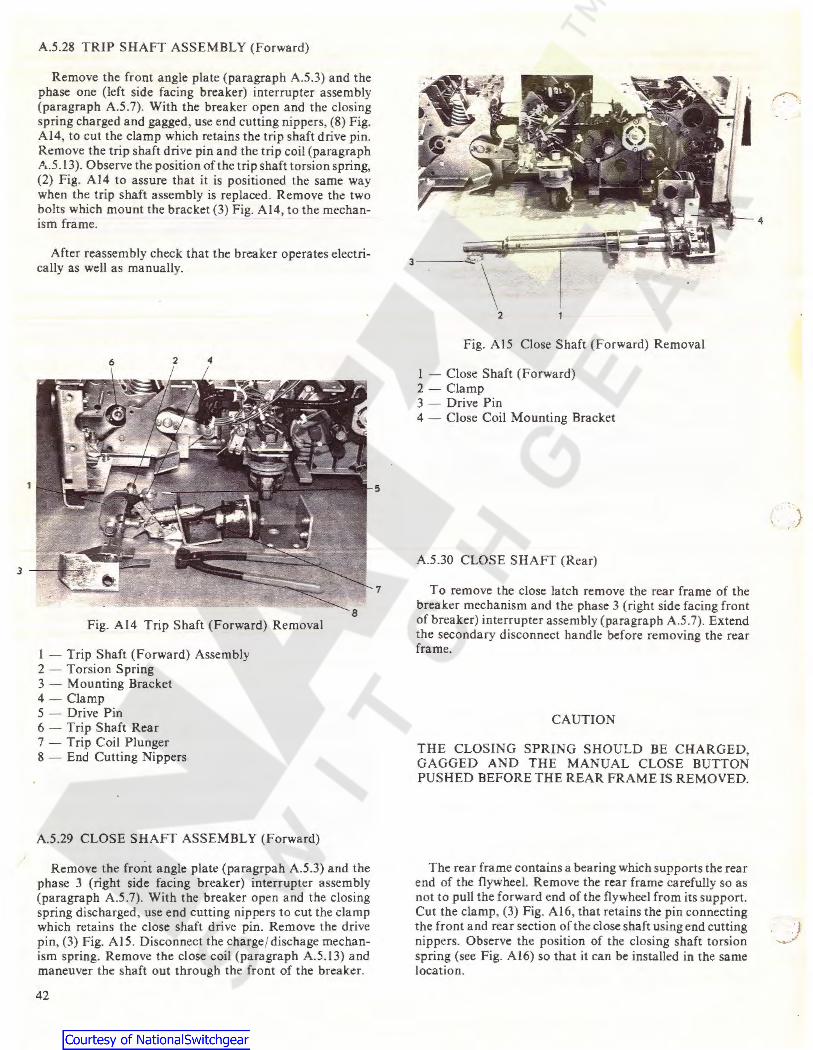
A.5.28 TRIP SHAFT ASSEMBLY (Forward)
Remove the front angle plate {paragraph A.5.3) and the phase one (left side facing breaker) interrupter assembly (paragraph A.5.7). With the breaker open and the closing spring charged and gagged, use end cutting nippers, (8) Fig. Al4, to cut the clamp which retains the trip shaft drive pin. Remove the trip shaft drive pin and the trip coil (paragraph A.5.13). Observe the position of the trip shaft torsion spring, (2) Fig. Al4 to assure that it is positioned the same way when the trip shaft assembly is replaced. Remove the two bolts which mount the bracket (3) Fig. Al4, to the mechanism frame.
After reassembly check that the breaker operates electrically as well as manually.
6 2 4
Fig. Al4 Trip Shaft (Forward) Removal
1 - Trip Shaft (Forward) Assembly 2 - Torsion Spring 3 - Mounting Bracket 4 - Clamp 5 - Drive Pin 6 - Trip Shaft Rear 7 - Trip Coil Plunger 8 - End Cutting Nippers
A.5.29 CLOSE SHAFT ASSEMBLY (Forward)
Remove the front angle plate (paragrpah A.5.3) and the phase 3 (right side facing breaker) interrupter assembly (paragraph A.5.7). With the breaker open and the closing spring discharged, use end cutting nippers to cut the clamp which retains the close shaft drive pin. Remove the drive pin, (3) Fig. Al 5. Disconnect the charge/ dischage mechanism spring. Remove the close coil (paragraph A.5.13) and maneuver the shaft out through the front of the breaker.
42
5
7
Fig. Al5 Close Shaft (Forward) Removal
1 - Close Shaft (Forward) 2 - Clamp 3 - Drive Pin 4 - Close Coil Mounting Bracket
A.5.30 CLOSE SHAFT (Rear)
To remove the close latch remove the rear frame of the breaker mechanism and the phase 3 (right side facing front of breaker) interrupter assembly (paragraph A.5.7). Extend the secondary disconnect handle before removing the rear frame.
CAUTION
THE CLOSING SPRING SHOULD BE CHARGED, GAGGED AND THE MANUAL CLOSE BUTTON PUSHED BEFORE THE REAR FRAME IS REMOVED.
The rear frame contains a bearing which supports the rear end of the flywheel. Remove the rear frame carefully so as not to pull the forward end of the flywheel from its support. Cut the clamp, (3) Fig. Al6, that retains the pin connecting the front and rear section of the close shaft using end cutting nippers. Observe the position of the closing shaft torsion spring (see Fig. Al6) so that it can be installed in the same location.
4

Fig. Al6 Close Shaft (Rear) Viewed from below.
l - Close Shaft (rear) 2 - Close Shaft (Forward) 3 - Clamp 4 - Torsion Spring 5 - Gear Motor Limit Switch Operator
A.5.31 CLOSING SPRING
CAUTION
DONOTREMOVETHEGAGnNFROMTHENEW CLOSING SPRING ASSEMBLY UNTIL IT HAS BEEN INSTALLED IN THE BREAKER. THE CHARGED CLOSING SPRING CONTAINS VERY HIGH ENERGY WHICH COULD RESULT IN SEVERE INJURY IF RELEASED IN AN UNCONTROLLED MANNER.
A. SPRING ASSEMBLY CAN BE GAGGED To remove the closing spring charge and gag it and push
the manual close push button. Push the manual trip push button to assure that the breaker is open. Disconnect the closing spring assembly, (6) Fig. AIOa, by driving the roll pin out that connects the closing spring assembly to the flywheel block. The closing spring can then be removed through the bottom of the breaker.
B. SPRING ASSEMBLY DAMAGED AND CANNOT BE GAGGED
The closing spring can be removed by driving out the roll pin that connects the closing spring, (6) Fig. AlOa, shaft to the flywheel block and then removing the left rear wheel assembly and the closing spring gag interlock on the left side frame. THESE OPERATIONS MUST BE PERFORMED WITH THE CLOSING SPRING DISCHARGED. The end of the closing spring opposite the flywheel can then be forced down from the breaker frame and the closing spring shaft pulled out of the flywheel block.
s
CAUTION
THERE IS SOME COMPRESSION REMAINING IN THE CLOSING SPRING EVEN THOUGH IT IS DISCHARGED. USE A LONG BAR TO FORCE THE SPRING ASSEMBLY A WAY FROM THE FRAME AND DO NOT ST AND DIRECTLY IN LINE WITH THE DIRECTION OF THE SPRING FORCE SINCE SOME ENERGY WILL BE RELEASED WHEN THE SPRING CLEARS THE FRAME.
A.5.32 FLYWHEEL ASSEMBLY
Remove the closing spring (paragraph A.5.31) and the pull rod (paragraph A.5.21). Remove the flywheel brake paragraph A.5.20, (not applicable to -3 model design). Remove the pin retaining ring on the rear close shaft. Remove the spring for the closing spring gag interlock from the rear frame. Extend the secondary disconnect handle and remove the bolts which hold the rear frame to the mechanism frame. Carefully pull the rear frame away from the mechanism. Rotate the closing shaft to a position where it does not interfere with the flywheel and carefully slide the flywheel assembly out of the mechanism.
When reassembling, lift the gearmotor limit switch actuator, (5) Fig. Al6, before sliding the flywheel assembly into place. After reassembly perform a complete adjustment of the mechanism as described in section 5, Mechanical Checks and Adjustments, and then operate the breaker electrically several times before returning the breaker to service.
A.5.33 SPRING DISCHARGE INTERLOCK
With the breaker open and the closing spring discharged, remove the two bolts, (3) Fig. Al7, which mount the spring discharge interlock to the right side frame of the breaker. Remove the spring discharge interlock.
On reassembly check the adjustment of the close latch monitor switch, (2) Fig. Al7, as described in paragraph 5.9.
CAUTION
THE MET ALCLAD SWITCHGEAR MUST BE DEENERGIZED FOR THE FOLLOWING TEST.
Check that the spring discharge interlock performs its function by performing the interface test with the metalclad switchgear as described in GEK 39672 in the section "Spring Discharge Interlock".
43
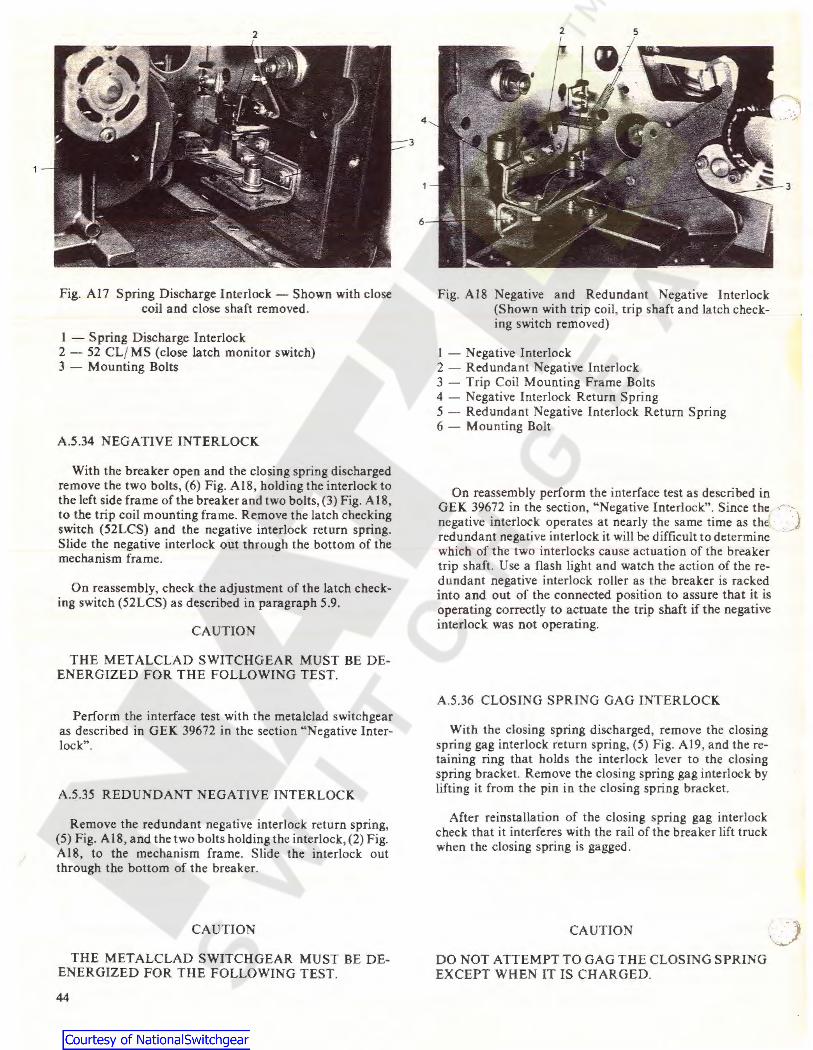
2
Fig. Al7 Spring Discharge Interlock - Shown with close coil and close shaft removed.
I - Spring Discharge Interlock 2 - 52 CL/ MS (close latch monitor switch) 3 - Mounting Bolts
A.5.34 NEGATIVE INTERLOCK
With the breaker open and the closing spring discharged remove the two bolts, (6) Fig. Al8, holding the interlock to the left side frame of the breaker and two bolts, (3) Fig. A 18, to the trip coil mounting frame. Remove the latch checking switch (52LCS) and the negative interlock return spring. Slide the negative interlock out through the bottom of the mechanism frame.
On reassembly, check the adjustment of the latch checking switch (52LCS) as described in paragraph 5.9.
CAUTION
THE MET ALCLAD SWITCHGEAR MUST BE DEENERGIZED FOR THE FOLLOWING TEST.
Perform the interface test with the metalclad switchgear as described in GEK 39672 in the section "Negative Interlock".
A.5.35 REDUNDANT NEGATIVE INTERLOCK
Remove the redundant negative interlock return spring, (5) Fig. Al8, and the two bolts holding the interlock, (2) Fig. Al8, to the mechanism frame. Slide the interlock out through the bottom of the breaker.
CAUTION
THE MET ALCLAD SWITCHGEAR MUST BE DEENERGIZED FOR THE FOLLOWING TEST.
44
3
2 5
Fig. Al8 Negative and Redundant Negative Interlock (Shown with trip coil, trip shaft and latch checking switch removed)
I - Negative Interlock 2 - Redundant Negative Interlock 3 - Trip Coil Mounting Frame Bolts 4 - Negative Interlock Return Spring 5 - Redundant Negative Interlock Return Spring 6 - Mounting Bolt
On reassembly perform the interface test as described in GEK 39672 in the section, "Negative Interlock". Since the negative interlock operates at nearly the same time as the redundant negative interlock it will be difficult to determine which of the two interlocks cause actuation of the breaker trip shaft. Use a flash light and watch the action of the redundant negative interlock roller as the breaker is racked into and out of the connected position to assure that it is operating correctly to actuate the trip shaft if the negative interlock was not operating.
A.5.36 CLOSING SPRING GAG INTERLOCK
With the closing spring discharged, remove the closing spring gag interlock return spring, (5) Fig. Al 9, and the retaining ring that holds the interlock lever to the closing spring bracket. Remove the closing spring gag interlock by lifting it from the pin in the closing spring bracket.
After reinstallation of the closing spring gag interlock check that it interferes with the rail of the breaker lift truck when the closing spring is gagged.
CAUTION
DO NOT ATTEMPT TO GAG THE CLOSING SPRING EXCEPT WHEN IT IS CHARGED.

I
A.5.37 RACKO UT ARM ASSEMBLY - ST AND ARD
Remove the two bolts holding the rackout arm, (2) Fig. 8, ) the breaker frame. Remove the two bolts holding the
rackout arm angle bracket to the front angle plate. No adjustments are required after reinstalling.
A.5.38 RACKOUT ARM ASSEMBLY - SIESMIC
The rackout arms for seismic breakers are similar to the standard rackout arms except that the support bracket is adjustable. The adjustment is made using a 'ii" open end wrench to turn an eccentric under the support bracket. The support bracket should be adjusted so that the distance between the support bracket and the short vertical section on the rackout arm is 1.000 + .030-.000 inches. This allows the rackout arm to engage the racking block on the racking mechanism installed in the equipment and limit the front to back freedom of the breaker.
After the rack out arm has been installed insert the breaker into the test position in the equipment and check that the rackout arm engages the racking block and that there is .030 inch maximum front to back freedom of movement.
Fig. Al9 Closing Spring Gag Interlock
(Shown in Unblocked Position)
I - Close Spring Interlock Lever 2 - Blocking Hole 3 - Close Spring Blocking Pin 4 - Storage Hole 5 - Interlock Lever Return Spring 6 - Retaining Ring
3
4
5
45

. GENERAL ELECTRIC COMPANY
MEDIUM VOLTAGE SWITCHGEAR BUSINESS SECTION BURLINGTON, IOWA 52601
..
GENERAL. ELECTRIC
(--~ . _.:;;)
l (__)


![[en] [de] - Gradient Gliders€¦ · Projected aspect ratio 4.16 4.16 4.16 4.16 4.16 Max. chord m 2.58 2.69 2.81 2.93 3.05 Min. chord m 0.62 0.64 0.67 0.70 0.73 Number of cells 51](https://img.pdfslide.us/doc/110x75/5f935f96abeb684e7251d926/en-de-gradient-gliders-projected-aspect-ratio-416-416-416-416-416-max.jpg)