Embed Size (px)
Citation preview

Instruction Sheet 1130100 WPC 2000 Option 1 Rev. C DA71124 April 2018 Page 1 Wintriss Controls Group 978-268-2700 toll free 800-586-8324
Instruction Sheet WPC 2000 Option 1 This document shows you how to install, wire, program, monitor, and troubleshoot WPC 2000 Option 1. Option 1 is compatible with WPC 2000 systems running WPC 2000 version 1.70 and higher and, in the case of WPC 2000 integrated units, SmartPAC 2 version 3.32 and higher. The document is organized in the following sections:
• Introduction (below)• Installing the Option 1 Board (page 3)• Wiring Option 1 User Inputs (page 6)• Changing User Input Stop Type (SmartPAC 2 Only) (page 10)• Viewing the Status of User Inputs (SmartPAC 2 Only) (page 13)• Troubleshooting (page 15)
Setup sheets and a wiring diagram for Option 1 user inputs appear at the end of the document. If you need additional help on any of the topics covered in this instruction sheet, refer to your WPC 2000 or SmartPAC 2 with WPC 2000 Integration user manual.
Introduction Option 1 is a “daughter” board you can install on your WPC 2000 Main Processor board to increase the number of user inputs available for connection of auxiliary equipment to WPC 2000. By providing connections for other press-related equipment, user inputs allow you to monitor auxiliary press functions such as lubrication systems, conveyors, etc. and provide additional press protection and operator safety. Up to 7 non-control-reliable inputs and up to 2 pairs of control-reliable, cross-checked inputs are standard on WPC 2000 units. The Option 1 board enables you to connect up to 20 additional non-control-reliable inputs and up to 4 additional control-reliable, cross-checked input pairs to WPC 2000 (see Table 1, next page).
DANGER!USER INPUTS 1 THROUGH 7 AND 12 THROUGH 31 NOT SUITABLE FOR SAFETY USE DO NOT use inputs 1 through 7 and 12 through 31 as part of any personnel protection system. These inputs are not control reliable. Failure to comply with these instructions will result in death or serious injury.
Option 1 user inputs, like WPC 2000 standard inputs, are programmed to stop the press whenever connected equipment malfunctions. The type of stop (e.g., top stop, emergency stop, etc.) is determined by the setting programmed for the specific input. For WPC 2000 standalone units, input stop types set at the factory cannot be changed; for WPC 2000 systems integrated with SmartPAC 2, default stop-type settings can be changed at the control (see “Changing User Input Stop Type (SmartPAC 2 Only),” page 10).
1130100 WPC 2000 Option 1
Page 2
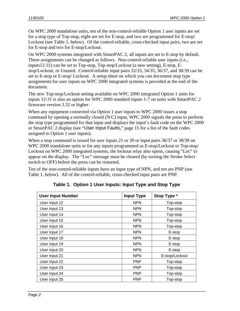
On WPC 2000 standalone units, ten of the non-control-reliable Option 1 user inputs are set for a stop type of Top-stop, eight are set for E-stop, and two are programmed for E-stop/ Lockout (see Table 1, below). Of the control-reliable, cross-checked input pairs, two are set for E-stop and two for E-stop/Lockout. On WPC 2000 systems integrated with SmartPAC 2, all inputs are set to E-stop by default. These assignments can be changed as follows. Non-control-reliable user inputs (i.e., inputs12-31) can be set to Top-stop, Top-stop/Lockout (a new setting), E-stop, E-stop/Lockout, or Unused. Control-reliable input pairs 32/33, 34/35, 36/37, and 38/39 can be set to E-stop or E-stop/ Lockout. A setup sheet on which you can document stop type assignments for user inputs on WPC 2000 integrated systems is provided at the end of the document. The new Top-stop/Lockout setting available on WPC 2000 integrated Option 1 units for inputs 12-31 is also an option for WPC 2000 standard inputs 1-7 on units with SmartPAC 2 firmware version 3.32 or higher. When any equipment connected via Option 1 user inputs to WPC 2000 issues a stop command by opening a normally closed (N/C) input, WPC 2000 signals the press to perform the stop type programmed for that input and displays the input’s fault code on the WPC 2000 or SmartPAC 2 display (see “User Input Faults,” page 15 for a list of the fault codes assigned to Option 1 user inputs). When a stop command is issued for user inputs 21 or 30 or input pairs 36/37 or 38/39 on WPC 2000 standalone units or for any inputs programmed as E-stop/Lockout or Top-stop/ Lockout on WPC 2000 integrated systems, the lockout relay also opens, causing “Loc” to appear on the display. The “Loc” message must be cleared (by turning the Stroke Select switch to OFF) before the press can be restarted. Ten of the non-control-reliable inputs have an input type of NPN, and ten are PNP (see Table 1, below). All of the control-reliable, cross-checked input pairs are PNP.
Table 1. Option 1 User Inputs: Input Type and Stop Type
User Input Number Input Type Stop Type * User input 12 NPN Top-stop User input 13 NPN Top-stop User input 14 NPN Top-stop User input 15 NPN Top-stop User input 16 NPN Top-stop User input 17 NPN E-stop User input 18 NPN E-stop User input 19 NPN E-stop User input 20 NPN E-stop User input 21 NPN E-stop/Lockout User input 22 PNP Top-stop User input 23 PNP Top-stop User input 24 PNP Top-stop User input 25 PNP Top-stop

WPC 2000 Option 1 1130100
Page 3
User Input Number Input Type Stop Type * User input 26 PNP Top-stop User input 27 PNP E-stop User input 28 PNP E-stop User input 29 PNP E-stop User input 30 PNP E-stop/Lockout User input 31 PNP E-stop User input 32 (cross-checked with input 33) PNP E-stop User input 33 (cross-checked with input 32) PNP E-stop User input 34 (cross-checked with input 35) PNP E-stop User input 35 (cross-checked with input 34) PNP E-stop User input 36 (cross-checked with input 37) PNP E-stop/Lockout User input 37 (cross-checked with input 36) PNP E-stop/Lockout User input 38 (cross-checked with input 39) PNP E-stop/Lockout User input 39 (cross-checked with input 38) PNP E-stop/Lockout * In WPC 2000 units integrated with SmartPAC 2, E-stop is the default stop type for all Option 1
user inputs. Default settings can be changed in SmartPAC 2. Option 1 inputs 12-31 can be programmed as Top-stop/ Lockout in addition to E-stop, Top-stop, E-stop/Lockout, and Unused. Input pairs 32/33, 34/35, 36/37, and 38/39 can only be set to E-stop or E-stop/ Lockout.
Installing the Option 1 Board To install the WPC 2000 Option 1 board (see Figure 1, next page) perform the following steps:
CAUTION DAMAGE TO BOARD FROM STATIC DISCHARGE Ground yourself before touching circuit boards or chips by touching a large metal object such as the press. Static electricity can destroy electronic components. Failure to comply with these instructions could result in property damage.
1. Making sure you are grounded, carefully unpack the Option 1 board and remove it from its anti-static bag.
NOTICE Be sure to save the shipping box and protective anti-static bag in case you need to return the Option 1 board.
2. Verify that the board has not been damaged during shipment. If damage has occurred, contact Wintriss Tech. Support immediately.

1130100 WPC 2000 Option 1
Page 4
Green Orange
438 439 440 441 442 443 444 445 446 447
431 432 433 434 435 436 437
448 449 450 451 452 453 454 455 456 457 458 459 460 461 462 463 464
WPC 2000Option 1 board
Standoffs andPhillips screws
(4 places)
WPC 2000 MainProcessor board
DSV/LockoutRelay board Auxiliary E-Stop
Relay board(Optional)
Figure 1. WPC 2000 Option 1 Board Installed on WPC 2000 Main Processor Board
WPC 2000 Option 1 1130100
Page 5
WARNING! ELECTRIC SHOCK HAZARD • Ensure that the power source is off before you replace electronic components in a
control. • Disconnect power from the machinery it is connected to before replacing electronic
components. This includes disconnecting power to the machine control and motor. • Ensure that servicing is performed by qualified personnel. Failure to comply with these instructions could result in death or serious injury.
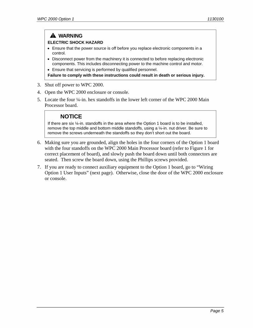
3. Shut off power to WPC 2000. 4. Open the WPC 2000 enclosure or console. 5. Locate the four ¼-in. hex standoffs in the lower left corner of the WPC 2000 Main
Processor board.
NOTICE If there are six ¼-in. standoffs in the area where the Option 1 board is to be installed, remove the top middle and bottom middle standoffs, using a ¼-in. nut driver. Be sure to remove the screws underneath the standoffs so they don’t short out the board.
6. Making sure you are grounded, align the holes in the four corners of the Option 1 board with the four standoffs on the WPC 2000 Main Processor board (refer to Figure 1 for correct placement of board), and slowly push the board down until both connectors are seated. Then screw the board down, using the Phillips screws provided.
7. If you are ready to connect auxiliary equipment to the Option 1 board, go to “Wiring Option 1 User Inputs” (next page). Otherwise, close the door of the WPC 2000 enclosure or console.

1130100 WPC 2000 Option 1
Page 6
Wiring Option 1 User Inputs Wiring connections for WPC 2000 Option 1 user inputs are made on terminal blocks TB601 and TB602 on the Option 1 board (see Figure 2, below). Pin numbers are shown in Tables 2 (next page) and 3 (page 7) and in Figure A at the end of this document.
+5VA processor
LEDDS630
+5VB processorLEDDS629
438 439 440 441 442 443 444 445 446 447
431 432 433 434 435 436 437
448 449 450 451 452 453 454 455 456 457 458 459 460 461 462 463 464
TB602 user input wiring connectorsTB601 user input wiring connectors
Group 8 LEDs Group 9 LEDs Group 11 LEDsGroup 10 LEDs
Figure 2. WPC 2000 Option 1 Board: Wiring Connections
Wire from the terminal shown in Table 2 or 3 to your equipment and then back to either +24 VDC or ground. On WPC 2000 standalone systems, if you remove any of the jumpers installed at the factory, make sure to bypass those inputs by connecting them to +24 VDC or ground, as shown in Table 2 or 3. TB601 provides one +24 VDC terminal and one ground terminal for jumper connections. TB602 provides two +24 VDC terminals and two ground terminals.

WPC 2000 Option 1 1130100
Page 7
On WPC 2000 systems integrated with SmartPAC 2, if the factory-installed jumpers are removed, those user inputs must be bypassed either by connecting them to +24 VDC or ground or by setting the stop type to Unused in SmartPAC 2 (see “Changing User Input Stop Type (SmartPAC 2 Only),” page 10).
When you have finished wiring user inputs, check the LEDs for the appropriate pin numbers to make sure that your connections are good (see Figure 3, page 9). On WPC 2000 systems integrated with SmartPAC 2, you can also check whether user inputs are “on” by displaying the appropriate input status screen (see “Viewing the Status of User Inputs (SmartPAC 2 Only),” page 13).
Table 2. WPC 2000 Option 1 Board Wiring Connections: TB601
Pin # User Input Terminal for Jumper Bypass Connection
Upper Row 431 User input 32 + (cross-checked with user input 33) +24 VDC 432 User input 34 + (cross-checked with user input 35) +24 VDC 433 User input 12 - Ground 434 User input 13 - Ground 435 User input 14 - Ground 436 User input 15 - Ground 437 +24 V
Lower Row 448 User input 22 + +24 VDC 449 User input 23 + +24 VDC 450 User input 24 + +24 VDC 451 User input 25 + +24 VDC 452 User input 36 + (cross-checked with user input 37) +24 VDC 453 User input 38 + (cross-checked with user input 39) +24 VDC 454 Ground
Table 3. WPC 2000 Option 1 Board Wiring Connections: TB602
Pin # User Input Terminal for Jumper Bypass Connection
Upper Row 438 User input 33 + (cross-checked with user input 32) +24 VDC 439 User input 35 + (cross-checked with user input 34) +24 VDC 440 User input 16 - Ground 441 User input 17 - Ground 442 User input 18 - Ground 443 User input 19 - Ground 444 User input 20 - Ground 445 User input 21 - Ground

1130100 WPC 2000 Option 1
Page 8
446 +24 V 447 +24 V
Lower Row 455 User input 26 + +24 VDC 456 User input 27 + +24 VDC 457 User input 28 + +24 VDC 458 User input 29 + +24 VDC 459 User input 30 + +24 VDC 460 User input 31 + +24 VDC 461 User input 37 + (cross-checked with user input 36) +24 VDC 462 User input 39 + (cross-checked with user input 38) +24 VDC 463 Ground 464 Ground

WPC 2000 Option 1 1130100
Page 9
GROUP 9
436 - User input 15 -
431 - User input 32 + (x-ch. w/33)432 - User input 34 + (x-ch. w/35)
433 - User input 12 -434 - User input 13 -
435 - User input 14 -
GROUP 8
453 - User input 38 + (x-ch. w/39)
448 - User input 22 +449 - User input 23 +
450 - User input 24 +451 - User input 25 +
452 - User input 36 + (x-ch. w/37)
GROUP 11
445 - User input 21 -
438 - User input 33 + (x-ch. w/32)439 - User input 35 + (x-ch. w/34)
440 - User input 16 -441 - User input 17 -
442 - User input 18 -443 - User input 19 -
444 - User input 20 -
GROUP 10
462 - User input 39 + (x-ch. w/38)
455 - User input 26 +456 - User input 27 +
457 - User input 28 +458 - User input 29 +
459 - User input 30 +460 - User input 31 +
461 - User input 37+ (x-ch. w/36)
+ 5 VDC A + 5 VDC B
Serial port Receive and Transmit LEDs on Main Processor board (visible through holes in Option 1 board)
Shaded LEDs are green; all others are red. LEDs in each group are identified by number.Corresponding pin numbers for each LED are also shown.
632 41 5 6532 84 71
632 41 5 6532 84 71
Figure 3. WPC 2000 Option 1 Board: LED Map
1130100 WPC 2000 Option 1
Page 10
Changing User Input Stop Type (SmartPAC 2 Only) WPC 2000 Option 1 user inputs are set to specified stop types at the factory (see Table 1, page 2). Option 1 stop types cannot be changed on WPC 2000 standalone units, but stop type defaults can be modified on systems integrated with SmartPAC 2. User inputs 12-31 can be set to Top-stop, Top-stop/Lockout (a new setting), E-stop, E-stop/Lockout, or Unused. Cross-checked input pairs 32/33, 34/35, 36/37, and 38/39 can be set to E-stop or E-stop/ Lockout. Top-stop/Lockout is also available as an option for WPC 2000 user inputs 1-7 if you have SmartPAC 2 firmware version 3.32 or higher. The Unused setting can be selected to bypass inputs you are not connecting.
NOTICE You cannot program control-reliable, cross-checked inputs 32-39 (or inputs 8-11 in WPC 2000) as Top-stop/Lockout or Unused. These safety inputs must be set as either E-stop or E-stop/Lockout.
You can assign names to the auxiliary equipment you are connecting to Option 1 inputs on the same screen on which you set the input stop type. A setup sheet on which you can document equipment name/user input assignments are provided at the end of the document. To change the stop type for a user input, follow these instructions:
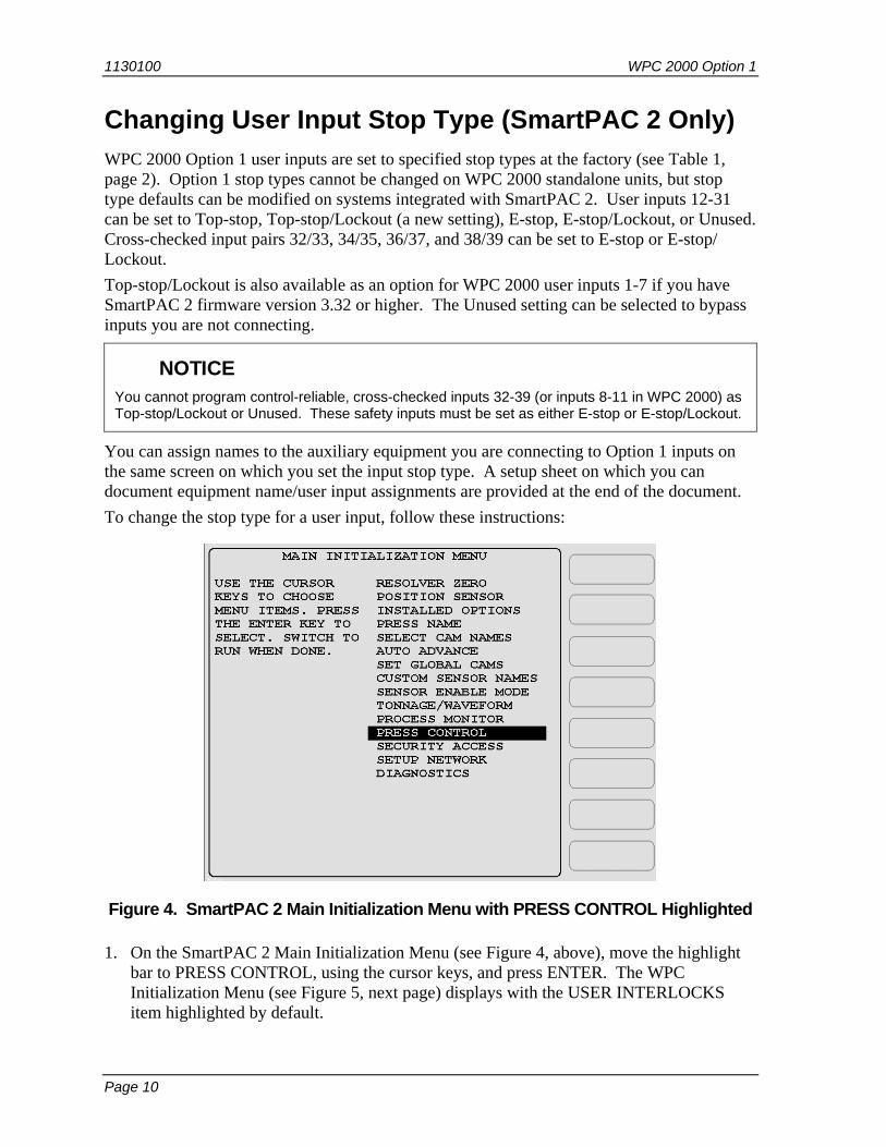
Figure 4. SmartPAC 2 Main Initialization Menu with PRESS CONTROL Highlighted
1. On the SmartPAC 2 Main Initialization Menu (see Figure 4, above), move the highlight bar to PRESS CONTROL, using the cursor keys, and press ENTER. The WPC Initialization Menu (see Figure 5, next page) displays with the USER INTERLOCKS item highlighted by default.

WPC 2000 Option 1 1130100
Page 11
Figure 5. WPC Initialization Menu with USER INTERLOCKS Highlighted
2. On the WPC Initialization Menu, press ENTER with USER INTERLOCKS highlighted. The Change User Interlocks screen, shown in Figure 6, below, displays.
F1
F2
F3
F4
F5
F6
F7
F8
Figure 6. Change User Interlocks Screen
1130100 WPC 2000 Option 1
Page 12
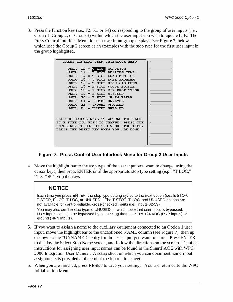
3. Press the function key (i.e., F2, F3, or F4) corresponding to the group of user inputs (i.e., Group 1, Group 2, or Group 3) within which the user input you wish to update falls. The Press Control Interlock Menu for that user input group displays (see Figure 7, below, which uses the Group 2 screen as an example) with the stop type for the first user input in the group highlighted.
Figure 7. Press Control User Interlock Menu for Group 2 User Inputs
4. Move the highlight bar to the stop type of the user input you want to change, using the cursor keys, then press ENTER until the appropriate stop type setting (e.g., “T LOC,” “T STOP,” etc.) displays.
NOTICE Each time you press ENTER, the stop type setting cycles to the next option (i.e., E STOP, T STOP, E LOC, T LOC, or UNUSED). The T STOP, T LOC, and UNUSED options are not available for control-reliable, cross-checked inputs (i.e., inputs 32-39). You may also set the stop type to UNUSED, in which case that user input is bypassed. User inputs can also be bypassed by connecting them to either +24 VDC (PNP inputs) or ground (NPN inputs).
5. If you want to assign a name to the auxiliary equipment connected to an Option 1 user input, move the highlight bar to the uncaptioned NAME column (see Figure 7), then up or down to the “UNNAMED” entry for the user input you want to name. Press ENTER to display the Select Stop Name screen, and follow the directions on the screen. Detailed instructions for assigning user input names can be found in the SmartPAC 2 with WPC 2000 Integration User Manual. A setup sheet on which you can document name-input assignments is provided at the end of the instruction sheet.
6. When you are finished, press RESET to save your settings. You are returned to the WPC Initialization Menu.

WPC 2000 Option 1 1130100
Page 13
Viewing the Status of User Inputs (SmartPAC 2 Only) You can view the status of WPC 2000 Option 1 user inputs just as you can view status of user inputs 1-11 in WPC 2000. Viewing input status is a useful diagnostic tool for troubleshooting your Option 1 user inputs and the auxiliary equipment they are connected to. To view input status, follow these steps:
Figure 8. WPC Initialization Menu with INPUT STATUS Highlighted
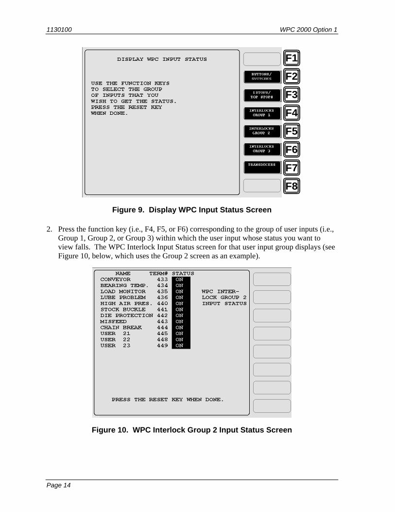
1. On the WPC Initialization Menu (see Figure 8, above), move the selection bar to INPUT STATUS, using the cursor keys, and press ENTER. The Display WPC Input Status screen, shown in Figure 9 (next page), displays.
1130100 WPC 2000 Option 1
Page 14
F1
F2
F3
F4
F5
F6
F7
F8
Figure 9. Display WPC Input Status Screen
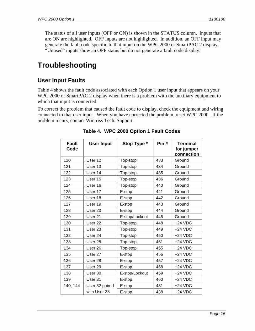
2. Press the function key (i.e., F4, F5, or F6) corresponding to the group of user inputs (i.e., Group 1, Group 2, or Group 3) within which the user input whose status you want to view falls. The WPC Interlock Input Status screen for that user input group displays (see Figure 10, below, which uses the Group 2 screen as an example).
Figure 10. WPC Interlock Group 2 Input Status Screen
WPC 2000 Option 1 1130100
Page 15
The status of all user inputs (OFF or ON) is shown in the STATUS column. Inputs that are ON are highlighted. OFF inputs are not highlighted. In addition, an OFF input may generate the fault code specific to that input on the WPC 2000 or SmartPAC 2 display. “Unused” inputs show an OFF status but do not generate a fault code display.
Troubleshooting
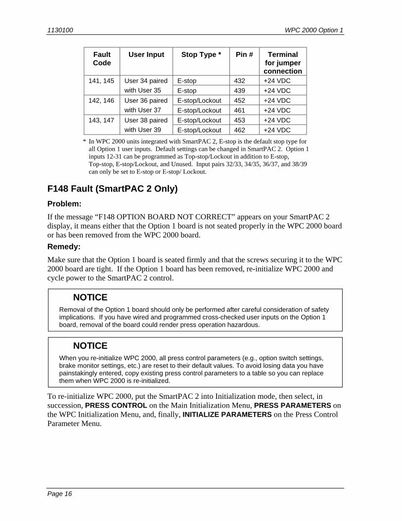
User Input Faults Table 4 shows the fault code associated with each Option 1 user input that appears on your WPC 2000 or SmartPAC 2 display when there is a problem with the auxiliary equipment to which that input is connected. To correct the problem that caused the fault code to display, check the equipment and wiring connected to that user input. When you have corrected the problem, reset WPC 2000. If the problem recurs, contact Wintriss Tech. Support.
Table 4. WPC 2000 Option 1 Fault Codes
Fault Code
User Input Stop Type * Pin # Terminal for jumper connection
120 User 12 Top-stop 433 Ground 121 User 13 Top-stop 434 Ground 122 User 14 Top-stop 435 Ground 123 User 15 Top-stop 436 Ground 124 User 16 Top-stop 440 Ground 125 User 17 E-stop 441 Ground 126 User 18 E-stop 442 Ground 127 User 19 E-stop 443 Ground 128 User 20 E-stop 444 Ground 129 User 21 E-stop/Lockout 445 Ground 130 User 22 Top-stop 448 +24 VDC 131 User 23 Top-stop 449 +24 VDC 132 User 24 Top-stop 450 +24 VDC 133 User 25 Top-stop 451 +24 VDC 134 User 26 Top-stop 455 +24 VDC 135 User 27 E-stop 456 +24 VDC 136 User 28 E-stop 457 +24 VDC 137 User 29 E-stop 458 +24 VDC 138 User 30 E-stop/Lockout 459 +24 VDC 139 User 31 E-stop 460 +24 VDC 140, 144 User 32 paired
with User 33 E-stop 431 +24 VDC E-stop 438 +24 VDC
1130100 WPC 2000 Option 1
Page 16
Fault Code
User Input Stop Type * Pin # Terminal for jumper connection
141, 145 User 34 paired with User 35
E-stop 432 +24 VDC E-stop 439 +24 VDC
142, 146 User 36 paired with User 37
E-stop/Lockout 452 +24 VDC E-stop/Lockout 461 +24 VDC
143, 147 User 38 paired with User 39
E-stop/Lockout 453 +24 VDC E-stop/Lockout 462 +24 VDC
* In WPC 2000 units integrated with SmartPAC 2, E-stop is the default stop type for all Option 1 user inputs. Default settings can be changed in SmartPAC 2. Option 1 inputs 12-31 can be programmed as Top-stop/Lockout in addition to E-stop, Top-stop, E-stop/Lockout, and Unused. Input pairs 32/33, 34/35, 36/37, and 38/39 can only be set to E-stop or E-stop/ Lockout.
F148 Fault (SmartPAC 2 Only) Problem: If the message “F148 OPTION BOARD NOT CORRECT” appears on your SmartPAC 2 display, it means either that the Option 1 board is not seated properly in the WPC 2000 board or has been removed from the WPC 2000 board. Remedy: Make sure that the Option 1 board is seated firmly and that the screws securing it to the WPC 2000 board are tight. If the Option 1 board has been removed, re-initialize WPC 2000 and cycle power to the SmartPAC 2 control.
NOTICE Removal of the Option 1 board should only be performed after careful consideration of safety
implications. If you have wired and programmed cross-checked user inputs on the Option 1 board, removal of the board could render press operation hazardous.
NOTICE When you re-initialize WPC 2000, all press control parameters (e.g., option switch settings,
brake monitor settings, etc.) are reset to their default values. To avoid losing data you have painstakingly entered, copy existing press control parameters to a table so you can replace them when WPC 2000 is re-initialized.
To re-initialize WPC 2000, put the SmartPAC 2 into Initialization mode, then select, in succession, PRESS CONTROL on the Main Initialization Menu, PRESS PARAMETERS on the WPC Initialization Menu, and, finally, INITIALIZE PARAMETERS on the Press Control Parameter Menu.

WPC 2000 Option 1 1130100
Page 17
F160 OPTION BOARD ID ERROR F160 OPTION BOARD ID ERROR
The installed option board is not supported by the current WPC 2000 firmware version.
Problem: The current WPC 2000 firmware is too old to recognize the Option Board ID. Remedy: Update the WPC 2000 firmware (see your WPC 2000 User Manual).
F163 Option Board Version Error F163 OPTION BOARD VERSION ERROR
The current Option Board firmware is not supported by the current WPC firmware version
Problem: The current WPC 2000 firmware is too old to recognize the Option Board firmware. Remedy: Update the WPC 2000 firmware (see your WPC 2000 User Manual). Alternatively, changing to an earlier version of the Option 1 firmware may allow the system to work.

WPC 2000 Standalone Option 1 Setup Sheet User Input Fault
Code Stop Type Pin # Terminal
for jumper connection
Name of Auxiliary Equipment
User 12 120 Top-stop 433 Ground User 13 121 Top-stop 434 Ground User 14 122 Top-stop 435 Ground User 15 123 Top-stop 436 Ground User 16 124 Top-stop 440 Ground User 17 125 E-stop 441 Ground User 18 126 E-stop 442 Ground User 19 127 E-stop 443 Ground User 20 128 E-stop 444 Ground User 21 129 E-stop/Lockout 445 Ground User 22 130 Top-stop 448 +24 VDC User 23 131 Top-stop 449 +24 VDC User 24 132 Top-stop 450 +24 VDC User 25 133 Top-stop 451 +24 VDC User 26 134 Top-stop 455 +24 VDC User 27 135 E-stop 456 +24 VDC User 28 136 E-stop 457 +24 VDC User 29 137 E-stop 458 +24 VDC User 30 138 E-stop/Lockout 459 +24 VDC User 31 139 E-stop 460 +24 VDC User 32 paired with User 33
140, 144 E-stop 431 +24 VDC E-stop 438 +24 VDC
User 34 paired with User 35
141, 145 E-stop 432 +24 VDC E-stop 439 +24 VDC
User 36 paired with User 37
142, 146 E-stop/Lockout 452 +24 VDC E-stop/Lockout 461 +24 VDC
User 38 paired with User 39
143, 147 E-stop/Lockout 453 +24 VDC E-stop/Lockout 462 +24 VDC

WPC 2000 Integrated Option 1 Setup Sheet User Input Fault
Code Stop Type * Pin # Terminal
for jumper connection
Name of Auxiliary Equipment (see step 5, page 12)
User 12 120 433 Ground User 13 121 434 Ground User 14 122 435 Ground User 15 123 436 Ground User 16 124 440 Ground User 17 125 441 Ground User 18 126 442 Ground User 19 127 443 Ground User 20 128 444 Ground User 21 129 445 Ground User 22 130 448 +24 VDC User 23 131 449 +24 VDC User 24 132 450 +24 VDC User 25 133 451 +24 VDC User 26 134 455 +24 VDC User 27 135 456 +24 VDC User 28 136 457 +24 VDC User 29 137 458 +24 VDC User 30 138 459 +24 VDC User 31 139 460 +24 VDC User 32 paired with User 33
140, 144 431 +24 VDC 438 +24 VDC
User 34 paired with User 35
141, 145 432 +24 VDC 439 +24 VDC
User 36 paired with User 37
142, 146 452 +24 VDC 461 +24 VDC
User 38 paired with User 39
143, 147 453 +24 VDC 462 +24 VDC
* E-stop is the default stop type for all Option 1 user inputs. In addition to E-stop, Top-stop, E-stop/Lockout, and Unused settings, Option 1 inputs 12-31 can also be programmed as Top-stop/Lockout. Input pairs 32/33, 34/35, 36/37, and 38/39 can only be set to E-stop or E-stop/ Lockout.