Embed Size (px)
Citation preview

IInnssttrruuccttiioonn SShheeeett FFoorr NNoo..55440000,, 55440011 && 55440022
Rev C9-12
No.5400-IS
11555 Dawson Drive, Camarillo, CA 93012 Phone 805-482-6913 • Fax 805-482-7422
A Division of Thiessen Products, Inc.
The JIMS “FORCEFLOW” CYLINDER HEAD COOLER is designed for the Twin Cam Models 1999 to pres-ent. Also fits all JIMS Twin Cam Race Engines. NOTE: These instructions show the installation of this product on a 2012 H-D Road Glide. This is probably
the most difficult model to install on. On the other H-D Twin Cam models you need to follow the samesteps in installation. There will be some minor differ-ences on each year or model wiring harness. It is high-ly recommended that you use the correct H-D servicemanual for reference in this installation. Refer to lastpage for parts list and for bubble reference callouts.
OPERATION AND OPTIONS: The FORCEFLOW COOLER comes with a thermostat thatactuates at 140 degrees along with an on/off cooler switch.It is the installer’s option to use the thermostat system we’vedesigned and where we recommend you locate it. If youchoose to relocate the thermostat it is your option andresponsibility of properly mounting. If you choose not to usethe thermostat it is your responsibility to safely disconnectthis system. Since JIMS hasn’t tested this product in theseoptional changes or locations, Jims cannot back any warran-ty issues in this area. IMPORTANT SAFETY ISSUE’S:We have designed the cooler to operate only when the igni-tion system is turned on by the operator as a safety factor.DO NOT MODIFY WIRING TO ALLOW COOLER TO OPER-ATE WITH THE IGNITION IN THE OFF POSITION. Warning: KEEP HANDS AWAY FROM MOVING FAN
BLADE! JIMS R&D Dept. tested the Forceflow cooler with a protected shroud around the fan blade andfound that it cooled better without a shroud. So with that said do not get your hands etc. nearthe blade when in operation. See Fig.A
Installation of the Forceflow Cooler is not intended to be a fix for a poorly tuned, or improper operatingfuel system such as running to lean or rich, causing bluing of pipes or engine damage.
Read the complete instructions before starting the installation of this product.JIMS cannot be responsible for the safety or quality of your work. If you do not know what youare doing then don’t do it. Take it to a professional. TOOLS AND SUPPLIES RECOMMENDED FOR INSTALLING THE “FORCEFLOW COOLER”.1. Common box end wrenches, ratchet and, socket set.2. Quality ft-lb torque wrench 3. Box cutter or knife to modify the “wiring trough”.4. The correct H-D Service Manual book per year and model you’re working on.5. Blue Threadlocker, JIMS No.4501 or equivalent. 6. Assorted wire tie wraps.
FIG.1
Horn mount
DANGERCooling Fan is exposed with NO finger guard. Throughtesting, it was found that a fan shroud would inhibit the wide pattern air flow &ultimately inhibit cooling. DO NOT TOUCH while in operation!
FIG.A
Install optional washers #5453 if needed.
IInnssttrruuccttiioonn SShheeeett FFoorr NNoo..55440000,, 55440011 && 55440022
Rev C9-12
No.5400-IS
22555 Dawson Drive, Camarillo, CA 93012 Phone 805-482-6913 • Fax 805-482-7422
A Division of Thiessen Products, Inc.
PREPARATION AND INSTALLATION1. Remove seat, and disconnect negative battery cable per
H-D Service Manual.2. Remove fuel tank, and, saddlebags, and side covers per
H-D Service Manual and side covers.3. Remove horn assembly with attached bracket per H-D
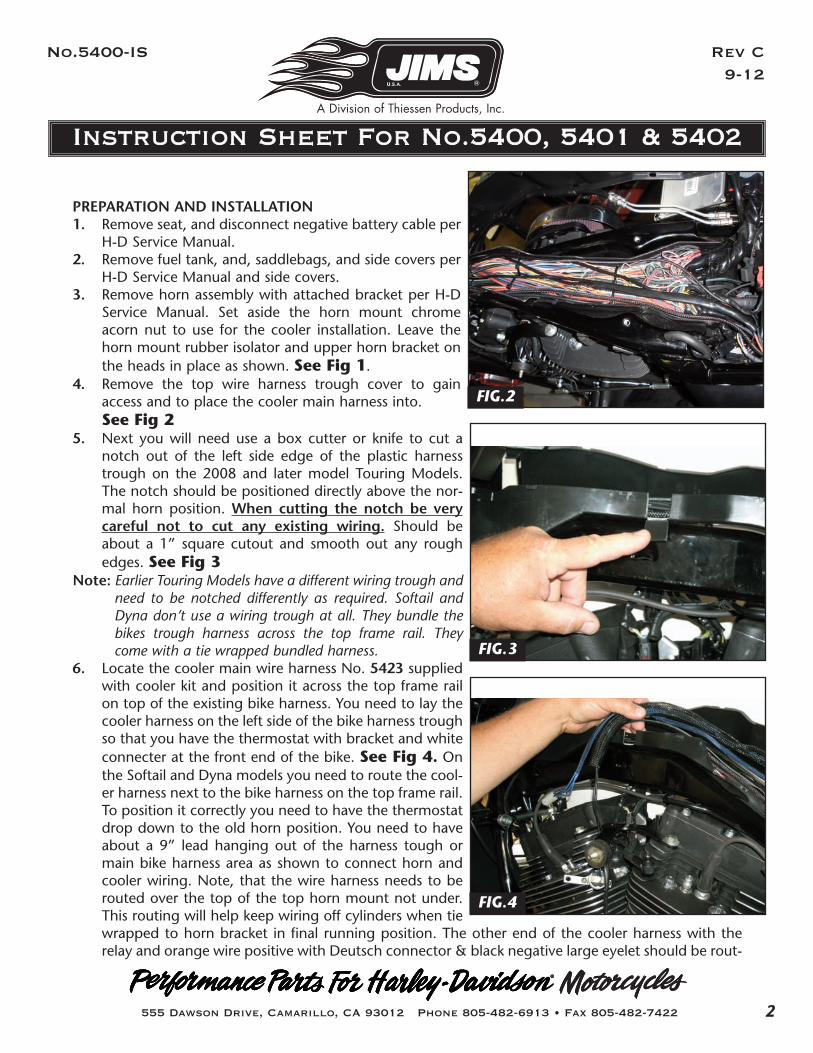
Service Manual. Set aside the horn mount chromeacorn nut to use for the cooler installation. Leave thehorn mount rubber isolator and upper horn bracket onthe heads in place as shown. See Fig 1.
4. Remove the top wire harness trough cover to gainaccess and to place the cooler main harness into. See Fig 2
5. Next you will need use a box cutter or knife to cut anotch out of the left side edge of the plastic harnesstrough on the 2008 and later model Touring Models.The notch should be positioned directly above the nor-mal horn position. When cutting the notch be verycareful not to cut any existing wiring. Should beabout a 1” square cutout and smooth out any roughedges. See Fig 3
Note: Earlier Touring Models have a different wiring trough andneed to be notched differently as required. Softail andDyna don’t use a wiring trough at all. They bundle thebikes trough harness across the top frame rail. Theycome with a tie wrapped bundled harness.
6. Locate the cooler main wire harness No. 5423 suppliedwith cooler kit and position it across the top frame railon top of the existing bike harness. You need to lay thecooler harness on the left side of the bike harness troughso that you have the thermostat with bracket and whiteconnecter at the front end of the bike. See Fig 4. Onthe Softail and Dyna models you need to route the cool-er harness next to the bike harness on the top frame rail.To position it correctly you need to have the thermostatdrop down to the old horn position. You need to haveabout a 9” lead hanging out of the harness tough ormain bike harness area as shown to connect horn andcooler wiring. Note, that the wire harness needs to berouted over the top of the top horn mount not under.This routing will help keep wiring off cylinders when tiewrapped to horn bracket in final running position. The other end of the cooler harness with therelay and orange wire positive with Deutsch connector & black negative large eyelet should be rout-
FIG.2
FIG.3
FIG.4

IInnssttrruuccttiioonn SShheeeett FFoorr NNoo..55440000,, 55440011 && 55440022
Rev C9-12
No.5400-IS
33555 Dawson Drive, Camarillo, CA 93012 Phone 805-482-6913 • Fax 805-482-7422
A Division of Thiessen Products, Inc.
ed back to the battery area. See Fig 5 7. Remove the front cylinder valve cover screw as shown.
See Fig 68. Locate the thermostat with mounting bracket on the
harness hanging down between the cylinders. Mountthe bracket No. 5434 with thermostat using No. 5439hex head bolt, No. 2014 washer, and spacer No. 5438to the valve cover as shown. Torque to 15-18 ft-lbsusing Blue Threadlocker JIMS No. 4501. At this locationthe thermostat will activate the fan at 140 degrees witha slight air gap. If you prefer to locate the thermostat ina different location then that’s your option. See Fig 5and Fig 7.
9. Remove the top center case bolt from the engine case.On a H-D OEM engine case you will have to remove theshifter rod nut and washers at the front gear shifter leverto get clearance to remove the OEM case bolt. See Fig 8
STOCK H-D ENGINE CASESSee Fig 9 Refer to call out bubbles in Fig 9 and lastinstruction page parts list for assembly reference.
A. If your engine cases are factory cases you need to locatethe 5/16”-18 case stud No. 5414 provided with thecooler parts.
B. Next lightly coat the threads on the end of stud No.5414 without the slot on it with Blue Threadlocker.
C. Insert the coated end of stud No. 5414 into the top cen-ter case bolt hole and tighten stud snug with a good flatblade screwdriver. Slide No.2014 flat washer onto thestud.
D. Coat I.D. of nut No. 1222 with Blue Threadlocker andthread on and torque to 15-19 ft-lbs using a 1/2” deepsocket and torque wrench.
E. Coat I.D of jam nut No. 5436 with Blue Threadlockerand thread onto the same stud but don’t tighten yet.
F. Next install AN-washer No. 1216 onto No. 5414 studagainst jam nut and then No. 5413 lower mount brack-et and another No.1216 AN-washer.
G. Install Blue Threadlocker to I.D. of acorn nut No. 5427and thread onto the stud. Before tightening position the lower bracket in the correct upright position using the box wrench tohold the previous loose jam nut No. 5436 to tighten against bracket. Now tighten acorn nut No.5327 to 8-9 ft-lbs with a 1/2” socket and torque wrench. See Fig 11
FIG.5
FIG.6
2016
619
FIG.7
Thermostat& Bracket
White 4-holeconnector

IInnssttrruuccttiioonn SShheeeett FFoorr NNoo..55440000,, 55440011 && 55440022
Rev C9-12
No.5400-IS
44555 Dawson Drive, Camarillo, CA 93012 Phone 805-482-6913 • Fax 805-482-7422
A Division of Thiessen Products, Inc.
H. Now fit up the shifter rod linkage and see if you haveadequate clearance when shifting. If your shift rod is hit-ting on the acorn nut then swap it out for a normalNo. 1222 nut we’ve provided in kit to gain more clear-ance. Check clearance again. If that doesn’t clear thenmove the jam nut on shaft inward. Retighten the out-side nut and check shift rod clearance. Then bolt upshift rod washer and nut. Move on to Step 10.
JIMS ENGINE RACE CASESFor information on installing this Forceflow cooler kit youshould have ordered a No. 5447 JIMS Engine hardwaremounting kit. Follow the instructions in that hardware kit toinstall the special top center case bolt hardware. Then pro-ceed back to this 5400-IS cooler instruction sheet and con-tinue on at step No.10. 10. Install finger tight for now No. 5419 rubber isolator to
the lower support bracket with No. 5437 AN- washerand No. 2017 nut as shown. See Fig 12
11. We are now ready to connect the wiring from the cool-er housing to the harness before hanging housing onthe motorcycle. We suggest you have another personhold the cooler housing while you connect to the twooriginal H-D horns flag connectors hanging downbetween the cylinders. These are two identical wirescoming out of the housing backing plate rubber grom-met. Fig 13
12. Connect the bikes two existing original horn flag typeterminal connectors to the light blue plastic blade type connector from the cooler housing. It does-n’t matter what blade goes to the two wires. See Fig 13
Note: For added insulation from weather, position existing shrink wrap and heat as required beforedoing the final positioning and tie wrapping also may add more shrink wrap if desired.
13. Next locate the cooler assembly backing plate upper and lower mounting tab holes on both the1/4” and 5/16” rubber isolator studs. If the assembly looks like its centered then you should do thefinal tightening of the previously finger tightened lower No. 2017 nut to the rubber isolator andlower bracket. If you cannot align the upper and lower rubber isolator studs to the backing platetab holes with out forcing them, causing distortion to the isolators, then you need to space up thehorn or motor mount bracket. You will need to add one thick washer No 5453 to each side hornmount. Place these washers under the horn or motor mount bracket. Try just one pair of washersor if needed stack two an each side of mount as shown. See Fig 1
FIG.8
44
FIG.9For H-D engine case
To case
Slotted