Embed Size (px)
Citation preview

INSTRUCTION SHEET
Cable FittingsSeries: Star Teck™ Extreme STE050 to STE400
Cab
le F
itti
ng
s| In
stru
ctio
n s
hee
t | T
A0
1766
M
—We reserve the right to make technical changes or modify the contents of this document without prior notice. With regard to purchase orders, the agreed particulars shall prevail. ABB does not accept any responsibility whatsoever for potential errors or possible lack of information in this document.
We reserve all rights in this document and in the subject matter and illustrations contained therein. Any reproduction – in whole or in part – is forbidden without prior written consent of ABB. Copyright© 2020 ABB. All rights reserved.
—tnb.abb.com (US/Latin America)tnb.ca.abb.com (Canada)abb.comWarranty:tnb.abb.com/ecpwarranty
Read and understand all instructions and safety information before use. Be aware of proper usage and potential hazards.
IMPORTANT
WARNING: Risk of shock, dis-connect power before installation.
CAUTION: Product should be installed by a qualified electrician in accordance with national and local electrical codes.
STE
Note: Design of fitting does not require disassembly.1. Select appropriate fitting to accommodate the enclosure
and cable used.2. Determine the working length (the length of conductors
required inside the enclosure or device). Remove a por-tion of the outer jacket to expose the armor, cut armor using a hacksaw and trim the outer jacket to adjust the exposed armor strip length as indicated in the table (Figure 1). CAUTION: Do not nick or cut the conductor insulation.
3. When preparing cable, the strip length is the same as the length of the glandnut, refer to the table (Figure 2).
4. Feed cable through gland funnel entry and push until ca-ble armor hits armor stop (Figure 3). Mispositioned cable armor may result in improper cable armor grounding.
Note: If inner conductor bundle will not pass through, re-move armor stop (See instruction 5).5. To remove armor stop, unscrew and discard (Figure 6).
Repeat Instruction 4.6. Tighten the gland nut until you obtain an appropriate
seal or to the maximum torque (see table) (Figure 4). The bushing and collar ring should seal evenly around the cable’s outer jacket and flush with glandnut face (Figure 5). Ensure the cable remains centered to obtain an optimal seal.
7. If disassembled, reassemble all components per assem-bly drawing. To reuse a fitting, new bushing, collar ring and grounding ring are required.
Figure 1 Figure 2
MIN MAX MIN MAXW/ARM
STOPW/O ARM
STOPSTE050 DATA 7/8 0.500 0.700 0.410 0.610 0.375 0.512
STE050 0.600 0.985 0.520 0.895 0.505 0.614STE075 3/4 600 0.860 1.205 0.780 1.125 0.645 0.818STE100 1 700 0.950 1.375 0.870 1.295 0.785 1.042STE125 1-1/4 1000 1.150 1.625 0.990 1.465 0.970 1.247STE150 1-1/2 1200 1.440 1.965 1.280 1.805 1.260 1.559STE200 2 1.825 2.375 1.665 2.215 1.645 1.972STE250 2-1/2 2.265 2.840 2.105 2.680 2.075 2.425STE300 3 2.670 3.270 2.545 3.145 2.531 2.891STE350 3-1/2 3.220 3.870 3.090 3.640 3.065 3.415STE400 4 3.665 4.340 3.550 4.225 3.525 3.915
A1 THROAT DIA MIN
(IN)
A2 THROAT DIA MIN (IN)
1/2 300
1-1/4
RANGE OVER JACKET (IN)
RANGE OVER ARMOR (IN)
1-3/4
16002-1/2
CAT NO. HUB SIZESTRIP
LENGTH (IN)
MAX. TORQUE (IN-LBS) See Step
6
Figure 3 Figure 4
Type H.L.A. Certified Class I,II,III. CSA File No. 23086Suitable for Class I Division 1 locations when used in combination with a certified Class I sealing fitting. Also suitable for Class I Division 2 when installed in accordance with the applicable electrical code.Certified for Ex e IIC: Suitable for Class I Zone 1 appli-cations where no arcing or sparking occur in normal service or under fault conditions.
UL listed file No. E38947Fittings meet sealing requirement for locationsType 4 (STE250 through STE400, in standard Aluminum & Suffix GR & S)Type 4X Enclosures (All sizes with Suffix BM & SS) Type 6P (STE050 through STE200, in standard Aluminum and Suffix GR, S, BN & SS)* STE200 through STE400 UL listed for corrugat-ed Aluminum Metal Clad Cable only. STE050 data UL listed with cables from 0.530 to 0.700 over jacket
Suffix Cat. No. with S=Steel, GR=Aluminum with aluminum grounding locknut, GRL=Aluminum with aluminum grounding locknut and aluminum grounding lug, KIT=refurbish kiti.e. STE050SProduct should be installed by a qualified electrician in accordance with national and local electrical codes.
Figure 5 Figure 6
TA0
1766
M
FEUILLE D‘INSTRUCTION
Raccords à câblesSérie: Star TeckMC Extreme STE050 à STE400
Rac
cord
à c
âble
s | F
euill
e d
‘inst
ruct
ion
| TA
017
66 M
—Nous nous réservons le droit d‘apporter des changements techniques ou de modifier le contenu de ce document sans préavis. En ce qui concerne les commandes d‘achat, les dispositions convenues s‘appliqueront. ABB décline toute responsabilité, quelle qu‘elle soit, en ce qui concerne des erreurs ou lacunes potentielles dans l‘information qui figure dans ce document.
Nous nous réservons tous les droits en ce qui concerne ce document ainsi que le sujet et les illustrations qu‘il contient. Toute reproduction, divulgation à des tiers ou utilisation de son contenu, en tout ou en partie, est interdite sans l‘accord écrit préalable d‘ABB.Copyright© 2020 ABB. Tous droits réservés.
—tnb.abb.com (US/Latin America)tnb.ca.abb.com (Canada)abb.comGarantie:tnb.abb.com/ecpwarranty
Remarque: Le raccord est conçu de manière à ne pas exiger de désassemblage.1. Choisir le raccord approprié selon le réceptacle et le
câble utilisés.2. Déterminer la longueur de travail (la longueur de con-
ducteur requise à l’intérieur du boîtier ou de l’appareil). Enlever une partie de la gaine extérieure pour exposer le blindage, couper l’armure à l’aide d’une scie à métaux et couper la gaine extérieure pour ajuster la longueur d’armure exposée comme indiqué dans le tableau (Fig-ure 1). ATTENTION de ne pas endommager ou couper la gaine des fils conducteurs.
3. Dans la préparation du câble, assurer une longueur de dénudage égale à la longueur du presse-étoupe. Con-sulter le tableau pour la longueur appropriée. (Figure 2)
4. Insérer le câble dans l’ouverture du presse-étoupe et le pousser jusqu’à ce que l’armure du câble s’appuie sur la butée (Figure 3). Si l’armure est mal positionnée, sa mise à la terre risque d’être compromise.
Remarque: S’il est impossible d’insérer le faisceau in-térieur de conducteurs, enlever la butée (voir étape 5).5. Pour enlever la butée, dévisser et mettre de côté (Fig-
ure 6). Répèter l’étape 4.6. Serrez l’écrou presse-étoupe jusqu’à ce que le joint soit
scellé de manière appropriée ou au couple maximum (voir tableau) (Figure 4). La garniture et l’anneau de blocage doivent couvrir de manière uniforme la gaine extérieure du câble et être au niveau de la face du presse-étoupe (Figure 5). Assurez-vous que le câble demeure centré afin d’obtenir une étanchéité optimale.
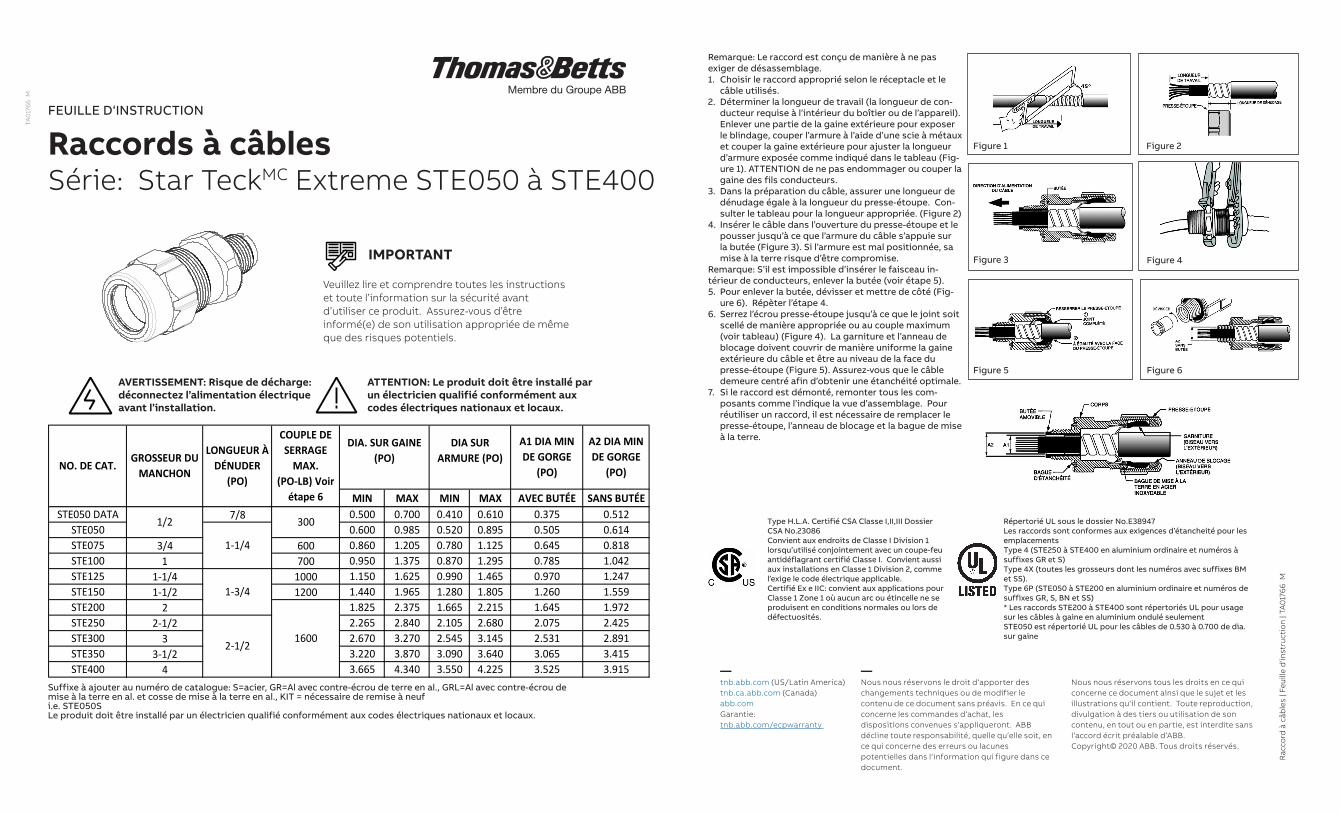
7. Si le raccord est démonté, remonter tous les com-posants comme l’indique la vue d’assemblage. Pour réutiliser un raccord, il est nécessaire de remplacer le presse-étoupe, l’anneau de blocage et la bague de mise à la terre.
Type H.L.A. Certifié CSA Classe I,II,III Dossier CSA No.23086Convient aux endroits de Classe I Division 1 lorsqu’utilisé conjointement avec un coupe-feu antidéflagrant certifié Classe I. Convient aussi aux installations en Classe 1 Division 2, comme l’exige le code électrique applicable.Certifié Ex e IIC: convient aux applications pour Classe 1 Zone 1 où aucun arc ou étincelle ne se produisent en conditions normales ou lors de défectuosités.
Répertorié UL sous le dossier No.E38947Les raccords sont conformes aux exigences d’étancheité pour les emplacementsType 4 (STE250 à STE400 en aluminium ordinaire et numéros à suffixes GR et S)Type 4X (toutes les grosseurs dont les numéros avec suffixes BM et SS).Type 6P (STE050 à STE200 en aluminium ordinaire et numéros de suffixes GR, S, BN et SS)* Les raccords STE200 à STE400 sont répertoriés UL pour usage sur les câbles à gaine en aluminium ondulé seulementSTE050 est répertorié UL pour les câbles de 0.530 à 0.700 de dia. sur gaine
MIN MAX MIN MAX AVEC BUTÉE SANS BUTÉESTE050 DATA 7/8 0.500 0.700 0.410 0.610 0.375 0.512
STE050 0.600 0.985 0.520 0.895 0.505 0.614STE075 3/4 600 0.860 1.205 0.780 1.125 0.645 0.818STE100 1 700 0.950 1.375 0.870 1.295 0.785 1.042STE125 1-1/4 1000 1.150 1.625 0.990 1.465 0.970 1.247STE150 1-1/2 1200 1.440 1.965 1.280 1.805 1.260 1.559STE200 2 1.825 2.375 1.665 2.215 1.645 1.972STE250 2-1/2 2.265 2.840 2.105 2.680 2.075 2.425STE300 3 2.670 3.270 2.545 3.145 2.531 2.891STE350 3-1/2 3.220 3.870 3.090 3.640 3.065 3.415STE400 4 3.665 4.340 3.550 4.225 3.525 3.915
1600
1/2
NO. DE CAT.GROSSEUR DU
MANCHON
LONGUEUR À DÉNUDER
(PO)
COUPLE DE SERRAGE
MAX. (PO-LB) Voir
étape 6
1-3/4
2-1/2
DIA SUR ARMURE (PO)
DIA. SUR GAINE (PO)
A1 DIA MIN DE GORGE
(PO)
A2 DIA MIN DE GORGE
(PO)
1-1/4
300
Suffixe à ajouter au numéro de catalogue: S=acier, GR=Al avec contre-écrou de terre en al., GRL=Al avec contre-écrou de mise à la terre en al. et cosse de mise à la terre en al., KIT = nécessaire de remise à neufi.e. STE050SLe produit doit être installé par un électricien qualifié conformément aux codes électriques nationaux et locaux.
Figure 1 Figure 2
Figure 3 Figure 4
Figure 5 Figure 6
Veuillez lire et comprendre toutes les instructions et toute l’information sur la sécurité avant d’utiliser ce produit. Assurez-vous d’être informé(e) de son utilisation appropriée de même que des risques potentiels.
IMPORTANT
AVERTISSEMENT: Risque de décharge: déconnectez l’alimentation électrique avant l’installation.
ATTENTION: Le produit doit être installé par un électricien qualifié conformément aux codes électriques nationaux et locaux.
STE
TA0
1766
M