Embed Size (px)
Citation preview
IM 12B06J09-01E-E 2nd edition
InstructionManual
Model IB100Interface Box
Screw
LED
IM 12B06J09-01E-E_ed02.indd 1 01/12/16 15:52
IM 12B06J09-01E-E
2Table of Contents
PREFACE 3
1. Introduction 41-1. Unpacking and Checking 41-2. Warranty and Service 41-3. Serial Number definition 41-4. Safety Precautions 41-5. Warning and Disclaimer 51-6. Copyright and Trademark Notices 5
2. Specifications 62-1. General 62-2. External Dimensions and Pin Assignment 72-3. Regulatory Compliance Statement 8
3. Notes on Handling 103-1. Safe use of this product 103-2. Check the Model and Specifications 10
4. Preparation 114-1. Installing or replacing batteries 114-2. Connecting the Cable Assy 114-3. Installation of SENCOM PC software SPS 24 114-4. Installation of Bluetooth adapter 11
5. Troubleshooting 12
6. Operation 126-1. Operation SENCOM PC Software 126-2. Operation LED of IB100 12
7. Model code 12
8. Spare parts 12
Appendix 1. EU Declaration of Conformity 13
Annex-1 14
Japanese manual 15
IM 12B06J09-01E-E_ed02.indd 2 01/12/16 15:52

IM 12B06J09-01E-E
3PREFACE
Thank you for purchasing the IB100 Interface Box.Please read the following respective documents before installing and using the IB100 Interface Box.These documents can be found in the package on the CD-ROM. The CD-ROM is a product of Yokogawa Electric Corporation.
Model Product name IM No.SPS24 Sencom PC software IM 12A01S02-01WU11 Interconnection cable IM 12B06W02-03
Please also read the instructions that are associated with the sensor.• The purpose of these user’s manuals is
not to warrant that the product is well suited to any particular purpose but rather to describe the functional details of the product.
• No part of the user’s manuals may be transferred or reproduced without prior written consent from YOKOGAWA.
• YOKOGAWA reserves the right to make improvements in the user’s manuals and product at any time, without notice or obligation.
• If you have any questions, or you find mistakes or omissions in the user’s manuals, please contact our sales representative or your local distributor.
Some drawings may be partially emphasized, simplified, or omitted, for the convenience of description.
IM 12B06J09-01E-E_ed02.indd 3 01/12/16 15:52

IM 12B06J09-01E-E
41. Introduction
1-1. Unpacking and CheckingUpon delivery, unpack the IB100 carefully and inspect it to ensure that it is not damaged during shipment. If damage is found, retain the original packing material and immediately notify the carrier and the relevant local Yokogawa Sales office. Make sure the Model Code and Serial Number on the IB100 are the same as on the packing list. Also check if option(s) that were ordered, are included and correct.
1-2. Warranty and ServiceYokogawa products are guaranteed free from defects in workmanship and materials under normal use and service for a period of (typically) 12 months from the date of shipment from the manufacturer. Individual Sales organizations can deviate from the typical warranty period, and the conditions of sale relating to the original purchase order should be consulted. Damage caused by wear and tear, inadequate maintenance, corrosion, or by the effects of chemical processes is excluded from this warranty coverage. In the event of a warranty claim, the defective goods should be sent (freight paid) to the Service Department of the relevant Yokogawa Sales office for repair or replacement (at Yokogawa’s discretion).
The following information must be included in the letter accompanying the returned goods:• Model Code and Serial Number.• Original Purchase Order and Date.• Length of time in service.• Description of the fault and circumstances
of the failure.• Process/environmental conditions that
may be related to the failure of the sensor.• Statement as to whether warranty or non-
warranty service is requested.• Complete shipping and billing instructions
for return of material, plus the name and phone number of a contact person that can be reached for further information.
1-3. Serial Number definitionThe Serial Number is defined by nine (9) alphanumeric characters:X1X2 Production Location X3X4 Year/Month code X5X6X7X8X9 Tracking number
Example: N3P600028See table 1 and 2.
1-4. Safety PrecautionsIn order to protect the system controlled by the product and the product itself and ensure safe operation, observe the safety precautions described in this user’s manual. We accept no liability for safety if users fail to observe these instructions when operating the product.
Method used for year/month numbering
Table 1: Production Year code
Year Year code Year Year code2014 P 2026 32015 R 2027 42016 S 2028 52017 T 2029 62018 U 2030 72019 V 2031 82020 W 2032 92021 X 2033 A2022 Y 2034 B2023 Z 2035 C2024 1 2036 D2025 2 2037 E
Table 2: Production Month code
Month Month codeJanuary 1February 2March 3April 4May 5June 6July 7August 8September 9October ANovember BDecember C
IM 12B06J09-01E-E_ed02.indd 4 01/12/16 15:52

IM 12B06J09-01E-E
5If this instrument is used in a manner not specified in this user’s manual, the protection provided by this instrument may be impaired.
If any protection or safety circuit is required for the system controlled by the product or for the product itself, prepare it separately.
Be sure to use the spare parts approved by Yokogawa Electric Corporation (hereafter simply referred to as YOKOGAWA) when replacing parts or consumables.
Modification of the product is strictly prohibited because it may be hazardous to operate. Please contact Yokogawa before making any repair or modificatoion.
The following safety symbols are used on the product as well as in this manual.
WARNINGThis symbol indicates that an operator must follow the instructions laid out in this manual in order to avoid the risks, for the human body, of injury, electric shock, or fatalities. The manual describes what special care the operator must take to avoid such risks.
CAUTIONThis symbol indicates that the operator must refer to the instructions in this manual in order to prevent the instrument (hardware) or software from being damaged, or a system failure from occurring.
1-5. Warning and DisclaimerThe product is provided on an “as is” basis. YOKOGAWA shall have neither liability nor responsibility to any person or entity with respect to any direct or indirect loss or damage arising from using the product or any defect of the product that YOKOGAWA cannot predict in advance.
1-6. Copyright and Trademark NoticesThe copyrights of online manual contained in the CD-ROM are reserved.The online manual is protected against modification by the PDF security, however it can be output via a printer. Printing out the online manual is only allowed for the purpose of using the product.When using the printed information of the online manual, check if the version is the most recent one by referring to the CD-ROM’s version.
No part of the online manual may be transferred, sold, distributed (including delivery via a commercial PC network or the like), or registered or recorded on video tapes.
Adobe, Acrobat and Acrobat Reader are either registered trademarks or trademarks of Adobe Systems Incorporated in the United States and/or other countries.All other company and product names mentioned in this user’s manual are trademarks or registered trademarks of their respective companies.
We do not use ™ or ® mark to indicate those trademarks or registered trademarks in this user’s manual.
IM 12B06J09-01E-E_ed02.indd 5 01/12/16 15:52
IM 12B06J09-01E-E
62. Specifications
2-1. General
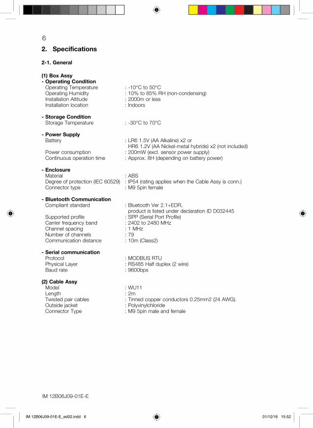
(1) Box Assy- Operating Condition
Operating Temperature : -10℃ to 50℃ Operating Humidity : 10% to 85% RH (non-condensing) Installation Altitude : 2000m or less Installation location : Indoors
- Storage Condition Storage Temperature : -30℃ to 70℃
- Power SupplyBattery : LR6 1.5V (AA Alkaline) x2 or
HR6 1.2V (AA Nickel-metal hybride) x2 (not included)Power consumption : 200mW (excl. sensor power supply)Continuous operation time : Approx. 8H (depending on battery power)
- EnclosureMaterial : ABSDegree of protection (IEC 60529) : IP54 (rating applies when the Cable Assy is conn.)Connector type : M9 5pin female
- Bluetooth CommunicationCompliant standard : Bluetooth Ver 2.1+EDR,
product is listed under declaration ID D032445Supported profile : SPP (Serial Port Profile)Carrier frequency band : 2402 to 2480 MHzChannel spacing : 1 MHzNumber of channels : 79Communication distance : 10m (Class2)
- Serial communicationProtocol : MODBUS RTUPhysical Layer : RS485 Half duplex (2 wire)Baud rate : 9600bps
(2) Cable AssyModel : WU11Length : 2mTwisted pair cables : Tinned copper conductors 0.25mm2 (24 AWG).Outside jacket : PolyvinylchlorideConnector Type : M9 5pin male and female
IM 12B06J09-01E-E_ed02.indd 6 01/12/16 15:52

IM 12B06J09-01E-E
72-2. External Dimensions and Pin Assignment
Fig. 1: Box Assy
Table 3: Pin assignment
Pin No. Signal description
1 Data -2 Data +3 Supply +4 Shield5 Supply Gnd
146 [5.75"]
88 [3
.46"
]
2 1
5
4
3
D
D
d
dMODEL CODE
Serial#
MODEL CODESerial#
WP
CN
L
L
1 2
3
4
5
2 1
5
4
3
Fig. 2: Pin assignment of Box Assy
Fig. 4: Pin assignment of female conn. Fig. 5: Pin assignment of male conn.
Fig. 3: Cable Assy
Dimensions in mm [inch]
IM 12B06J09-01E-E_ed02.indd 7 01/12/16 15:52

IM 12B06J09-01E-E
82-3. Regulatory Compliance StatementThis product is in compliance with the following standards.
CE (EU) : Decision 768/2008/EC- EMC : Directive 2014/30/EU
EN 61326-1: 2013 Class A, Table 2 (For use in industrial locations)- R&TTE : Directive 1999/5/EC
EN 300328 V1.9.1 EN 301489-1 V1.9.2 EN 301489-17 V2.2.1
- Low Voltage : Directive 2014/35/EU EN 61010-1: 2010 EN 62479: 2010 Pollution Degree 2, Installation Category I Pollution Degree describes the degree to which a solid, liquid, or gas which deteriorates dielectric strength or surface resistivity is adhering. “2” applies to normal indoor atmosphere. Normally only non-conductive pollution occurs, but occasionally temporary conductivity caused by condensation must be expected. Installation Category describes a number which defines a transient overvoltage condition. It implies the regulation for impulse withstand voltage. “I” applies for connection to circuits in which measures are taken to limit transient over voltages to an appropriately low level.
- RoHS2 : Directive 2011/65/EU EN50581: 2012
FCC (USA) : Part 15 subpart B : Part 15 subpart C (contains FCC ID: PI4411B)
This device complies with part 15 of the FCC Rules. Operation is subject to the following two conditions: (1) This device may not cause harmful interference, and (2) this device must accept any interference received, including interference that may cause undesired operation.
FCC CAUTION Changes or modifications not expressly approved by the party responsible for compliance could void the user’s authority to operate the equipment.
Note: This equipment has been tested and found to comply with the limits for a Class A digital device, pursuant to part 15 of the FCC Rules. These limits are designed to provide reasonable protection against harmful interference when the equipment is operated in a commercial environment. This equipment generates, uses, and can radiate radio frequency energy and, if not installed and used in accordance with the instruction manual, may cause harmful interference to radio communications. Operation of this equipment in a residential area is likely to cause harmful interference in which case the user will be required to correct the interference at his own expense.
This transmitter must not be co-located or operated in conjunction with any other antenna or transmitter.
This equipment complies with FCC radiation exposure limits set forth for an uncontrolled environment and meets the FCC radio frequency (RF) Exposure Guidelines. This equipment should be installed and operated keeping the radiator at least 20cm away from person’s body.
IM 12B06J09-01E-E_ed02.indd 8 01/12/16 15:52

IM 12B06J09-01E-E
9IC (Canada) : RSS-Gen : RSS-210 (contains IC: 1931B-BTM411) : RSS-102 : ICES-003
This Class A digital apparatus complies with Canadian ICES-003. Cet appareil numérique de la classe A est conforme à la norme NMB-003 du Canada.
This device complies with Industry Canada’s licence-exempt RSSs. Operation is subject to the following two conditions: (1) This device may not cause interference; and (2) This device must accept any interference, including interference that may cause undesired operation of the device.
Le présent appareil est conforme aux CNR d’Industrie Canada applicables aux appareils radio exempts de licence. L’exploitation est autorisée aux deux conditions suivantes : 1) l’appareil ne doit pas produire de brouillage; 2) l’utilisateur de l’appareil doit accepter tout brouillage radioélectrique
subi, même si le brouillage est susceptible d’en compromettre le fonctionnement.
This equipment complies with IC radiation exposure limits set forth for an uncontrolled environment and meets RSS-102 of the IC radio frequency (RF) Exposure rules. This equipment should be installed and operated keeping the radiator at least 20cm away from person’s body.
Cet équipement est conforme aux limites d’exposition aux rayonnements énoncées pour un environnement non contrôlé et respecte les règles d’exposition aux fréquences radioélectriques (RF) CNR-102 de l’IC. Cet équipement doit être installé et utilisé en gardant une distance de 20 cm ou plus entre le radiateur et le corps humain.
Radio law (Japan) : Construction design attestation number (204-320077).
This product is used the specific radio equipment that has received the construction design attestation in accordance with the Japanese radio law. Therefore, the licence of wireless station is not nessessary to use this product. However, changes or modifications of this product may be punishable by law.
Others - WEEE : Directive 2012/19/EU (for EU area only)
The following marking indicates that you must not discard this electrical/electronic product in domestic household waste. This device is classified as a monitoring and control instrument. Do not dispose this product in domestic household waste, contact your local Yokogawa office for details.
IM 12B06J09-01E-E_ed02.indd 9 01/12/16 15:52

IM 12B06J09-01E-E
103. Notes on Handling
The IB100 is fully factory-tested before shipment. When the IB100 is delivered, check the appearance for damage.
3-1. Safe use of this product
CAUTION
• The IB100 should only be used with equipment that meets the relevant EU, American, Canadian, and Japanese standards. Yokogawa accepts no responsibility for the misuse of this unit.
• The IB100 is packed carefully with shock absorbing materials, nevertheless, the IB100 may be damaged or broken if subjected to strong shock, such as if the IB100 is dropped. Handle with care.
• The IB100 contains devices that can be damaged by electrostatic discharge. When servicing the IB100, please observe proper procedures to prevent such damage.
• Replacement components should be shipped in conductive packaging. Repair work should be done at grounded workstations using grounded soldering irons and wrist straps to avoid electrostatic discharge.
• Do not use an abrasive or organic solvent in cleaning the IB100.
• Do not use AA Lithium battery.
The IB100 is an EN61326-1 Class A product, and it is designed for use in the industrial environment. Please use the IB100 in the industrial environment only.
3-2. Check the Model and Specifications
Verify that the Model and Suffix Code indicated on the nameplate attached to the Box Assy is compliance with them written on the order sheet.
IM 12B06J09-01E-E_ed02.indd 10 01/12/16 15:52

IM 12B06J09-01E-E
114. Preparation
4-1. Installing or replacing batteries
CAUTIONSelect a relatively moisture-free
location when installing batteries in the IB100. When installing batteries, observe correct polarity (battery orientation). Failure to do so may damage to the IB100. Remove batteries from the IB100 if it is to be stored for an extended period of time. Do not leave dead batteries in the IB100. They may leak and cause failure or erratic operation of the IB100. When replacing batteries, replace both batteries at the same time. If only one battery is replaced, the new battery may discharge into the old battery, which may leak chemicals and damage the IB100. Do not mix different types of batteries. It may cause failure.
Fig. 6 Loosen the screw holding the battery box cover.
Fig. 7 Remove the battery box cover and install the batteries observing polarity diagram inside. Installed properly, the blue color LED turns on. Put the cover back on and tighten the screw
Fig. 8 Connecting the Cable Assy
4-2. Connecting the Cable AssyConnect the male connector on the Cable Assy to the female connector on the Box Assy. Align the posts of the Cable Assy connector with the slots of the connector on the enclosure. Then tighten firmly by turning only the locknut.
4-3. Installation SENCOM PC software of SPS24
Insert this CD-ROM in your PC. If the installation program does not start automatically: execute the program “SPS24_Launcher.exe”.Select the desired language and click on “Install SENCOM PC Software SPS24”. This program will guide you through the installation.For IB100 the installation of the “driver for interface box” is not needed.
4-4. Installation of Bluetooth adapterThe SPS24 software needs a Bluetooth adapter to communicate with the IB100. This adapter is not included. Install the Bluetooth adapter by using the manual of the connection side of this device. Add the “Yokogawa IB100” device to your “Bluetooth Devices” in the Control Panel.This is only possible when the IB100 is in active state (see chapter 6-2).After this installation and restarting your PC (if needed) start the SENCOM PC Software. When the Bluetooth connection with “Yokogawa IB100” is active, the RS port can be selected in the Setup view.The Bluetooth driver always creates 2 communication ports. The correct port is the “SPP Dev” or Outgoing in the Bluetooth setting. Please chose the correct one in the SPS24 Setup view. (In most of cases, it is smaller number of communication port)
Screw
LED
Screw
LED
Screw
LED
IM 12B06J09-01E-E_ed02.indd 11 01/12/16 15:52

IM 12B06J09-01E-E
125. Troubleshooting
When the SENCOM PC Software does not connect to a SENCOM Sensor:• Make sure you have selected the correct
Communication port in the Setup view.• Re-connect the sensor physically
(see Fig. 8).• Make sure the cable is correctly
connected to the SENCOM Sensor and to the IB100.
• Make sure the Bluetooth device is working properly.
• Open the advanced hardware properties in the Bluetooth devices of the Control Panel. Allocate another free Communication port to the Bluetooth device “Yokogawa IB100”.
• Restart your PC.• Re-install the Bluetooth device
“Yokogawa IB100” and restart your PC.• Reset the IB100 by removing and
re-installing the batteries.• Replace the batteries for new batteries.
If this does not solve the problem, please contact your Yokogawa representative. The contact information per continent is printed on the last page of this manual.
6. Operation
6-1. Operation SENCOM PC SoftwareFor the usage of IB100, please read the User Manual of SPS24 which is stored on the included CD-ROM.
6-2. Operation LED of IB100When IB100 and SPS24 are connected successfully, the LED blinks about every 5 seconds.
When IB100 is not connected to SPS24 for a few minutes, the IB100 goes into “sleep mode”. In sleep mode the LED turns off and the IB100 cannot be Bluetooth connected. By re-connecting the sensor physically (see fig. 8), sleep mode is canceled and IB100 will be active (LED turns on again).
When the batteries are low on power, the LED will blink fast. Please replace the batteries immediately (see fig. 6 and 7).
7. Model code
Model Suffix Option Description code codeIB100 Interface box SENCOM with SPS24 softwareType -AB General purpose for EU, USA, JPN and CANOptions N/A
8. Spare parts
Spare part DescriptionWU11-M9-02-CN-V 2m interconnection cable
IM 12B06J09-01E-E_ed02.indd 12 01/12/16 15:52
IM 12B06J09-01E-E
13Appendix 1. EU Declaration of Conformity
YOKOGAWA
EU DECLARATION OF CONFORMITY
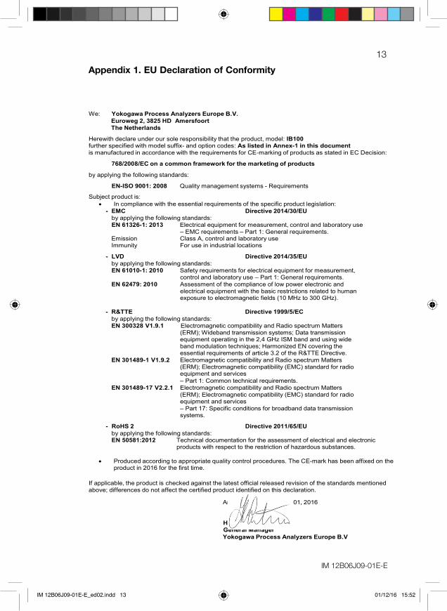
We: Yokogawa Process Analyzers Europe B.V. Euroweg 2, 3825 HD Amersfoort The Netherlands
Herewith declare under our sole responsibility that the product, model: IB100 further specified with model suffix- and option codes: As listed in Annex-1 in this document is manufactured in accordance with the requirements for CE-marking of products as stated in EC Decision:
768/2008/EC on a common framework for the marketing of products
by applying the following standards:
EN-ISO 9001: 2008 Quality management systems - Requirements
Subject product is:
In compliance with the essential requirements of the specific product legislation: - EMC Directive 2014/30/EU
by applying the following standards: EN 61326-1: 2013 Electrical equipment for measurement, control and laboratory use
– EMC requirements – Part 1: General requirements. Emission Class A, control and laboratory use Immunity For use in industrial locations
- LVD Directive 2014/35/EU
by applying the following standards: EN 61010-1: 2010 Safety requirements for electrical equipment for measurement,
control and laboratory use – Part 1: General requirements. EN 62479: 2010 Assessment of the compliance of low power electronic and
electrical equipment with the basic restrictions related to human exposure to electromagnetic fields (10 MHz to 300 GHz).
- R&TTE Directive 1999/5/EC
by applying the following standards: EN 300328 V1.9.1 Electromagnetic compatibility and Radio spectrum Matters
(ERM); Wideband transmission systems; Data transmission equipment operating in the 2,4 GHz ISM band and using wide band modulation techniques; Harmonized EN covering the essential requirements of article 3.2 of the R&TTE Directive.
EN 301489-1 V1.9.2 Electromagnetic compatibility and Radio spectrum Matters (ERM); Electromagnetic compatibility (EMC) standard for radio equipment and services
– Part 1: Common technical requirements. EN 301489-17 V2.2.1 Electromagnetic compatibility and Radio spectrum Matters
(ERM); Electromagnetic compatibility (EMC) standard for radio equipment and services
– Part 17: Specific conditions for broadband data transmission systems.
- RoHS 2 Directive 2011/65/EU
by applying the following standards: EN 50581:2012 Technical documentation for the assessment of electrical and electronic products with respect to the restriction of hazardous substances.
Produced according to appropriate quality control procedures. The CE-mark has been affixed on the
product in 2016 for the first time.
If applicable, the product is checked against the latest official released revision of the standards mentioned above; differences do not affect the certified product identified on this declaration.
Amersfoort – September 01, 2016 H. Leijten General Manager Yokogawa Process Analyzers Europe B.V 1/2
IM 12B06J09-01E-E_ed02.indd 13 01/12/16 15:52

IM 12B06J09-01E-E
14Annex-1
Model Suffix Option Description code codeIB100 Interface box SENCOM with SPS24 softwareType -AB General purpose for EU, USA, JPN and CANOptions N/A
Further specifications can be found in General Specification Sheet GS 12B06J09-01E-E.
IM 12B06J09-01E-E_ed02.indd 14 01/12/16 15:52
IM 12B06J09-01E-E
15
まえがき
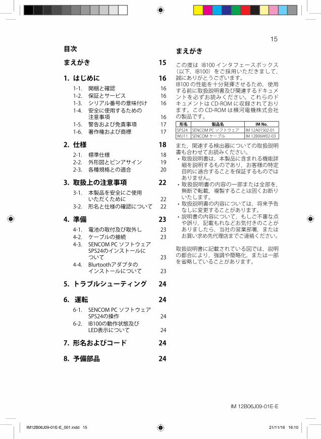
この度は IB100 インタフェースボックス(以下,IB100)をご採用いただきまして,
誠にありがとうございます。IB100 の性能を十分発揮させるため,使用する前に取扱説明書及び関連するドキュメントを必ずお読みください。これらのドキュメントは CD-ROM に収録されております。この CD-ROM は横河電機株式会社の製品です。
形名 製品名 IM No.SPS24 SENCOM PC ソフトウェア IM 12A01S02-01WU11 SENCOM ケーブル IM 12B06W02-03
また,関連する検出器についての取扱説明書も合わせてお読みください。• 取扱説明書は,本製品に含まれる機能詳
細を説明するものであり,お客様の特定目的に適合することを保証するものではありません。
• 取扱説明書の内容の一部または全部を,無断で転載,複製することは固くお断りいたします。
• 取扱説明書の内容については,将来予告なしに変更することがあります。
• 説明書の内容について,もしご不審な点や誤り,記載もれなどお気付きのことがありましたら,当社の営業部署,またはお買い求め先代理店までご連絡ください。
取扱説明書に記載されている図では,説明の都合により,強調や簡略化,または一部を省略していることがあります。
目次
まえがき 15
1. はじめに 161-1. 開梱と確認 161-2. 保証とサービス 161-3. シリアル番号の意味付け 161-4. 安全に使用するための
注意事項 161-5. 警告および免責事項 171-6. 著作権および商標 17
2. 仕様 182-1. 標準仕様 182-2. 外形図とピンアサイン 192-3. 各種規格との適合 20
3. 取扱上の注意事項 223-1. 本製品を安全にご使用
いただくために 223-2. 形名と仕様の確認について 22
4. 準備 234-1. 電池の取付及び取外し 234-2. ケーブルの接続 234-3. SENCOMPCソフトウェア
SPS24のインストールについて 23
4-4. Blurtoothアダプタのインストールについて 23
5. トラブルシューティング 24
6. 運転 246-1. SENCOMPCソフトウェア
SPS24の操作 246-2. IB100の動作状態及び
LED表示について 24
7. 形名およびコード 24
8. 予備部品 24
IM12B06J09-01E-E_001.indd 15 21/11/16 16:10

IM 12B06J09-01E-E
161. はじめに
1-1. 開梱と確認IB100 が届きましたら,十分に気を付けて開梱を行い,輸送時の損傷がないことを確認してください。もし損傷が見つかりましたら,元の梱包材に戻し,すぐに輸送業者と関連する当社担当営業所に連絡してください。IB100 の形名とシリアル番号が梱包リストと同じであることを確認してください。オプションも合わせて購入された場合は,それらが正しく含まていることも確認してください。
1-2. 保証とサービス当社の製品および部品に関して,工場出荷日から(通常)12 か月の期間,正常な使用の下での製造上の欠陥に対する保証を行います。ただし,通常保証期間は,各営業所で変更できるものとし,購入注文書の販売条件に従うこととします。摩耗や破損,不適切な保守作業,腐食,化学工程の影響による損害については,本保証の対象外とします。保証請求の際は,不適合製品を担当営業所のサービス担当までお送りください(送料お客様負担)。当社の判断により交換または修理を行います。
製品を送付する際には,必ず下記の情報を記載した文書を添付してください。• 形名,シリアル番号• 購入注文書および購入日• 使用期間• 不適合の内容,発生状況• 不適合に関連すると考えられるプロセス
や環境の状況• 保証対象の有無,保証内修理または保証
外修理• お客様への返送方法,請求書送付先の詳
細(ご担当者の名前,電話番号)
1-3. シリアル番号の意味付けシリアル番号は以下の 9 桁の英数字で構成されています。X1X2 製造場所X3X4 製造年 / 月コードX5X6X7X8X9 問い合わせ番号
シリアル番号例 : N3P600028(表 1,2 を参照)
1-4. 安全に使用するための注意事項本製品および本製品で制御するシステムの保護・安全のため,本製品を取り扱う際は,説明書に記載されている安全に関する指示事項に従ってください。なお,これらの指示事項に反する扱いをされた場合,当社は安全性の保証をいたしかねます。
製造年 / 月コードの一覧
表 1. 製造年コード
年 年コード 年 年コード2014 P 2026 32015 R 2027 42016 S 2028 52017 T 2029 62018 U 2030 72019 V 2031 82020 W 2032 92021 X 2033 A2022 Y 2034 B2023 Z 2035 C2024 1 2036 D2025 2 2037 E
表 2. 製造月コード
月 月コード1 月 12 月 23 月 34 月 45 月 56 月 67 月 78 月 89 月 910 月 A11 月 B12 月 C
IM12B06J09-01E-E_001.indd 16 21/11/16 16:10

IM 12B06J09-01E-E
17この説明書で指定していない方法で使用すると,本製品の保護機能が損なわれることがあります。
本製品および本製品で制御するシステムに対する保護・安全回路を設置する場合は,本製品外部に別途用意するようお願いいたします。
本製品の部品や消耗品を交換する場合は,必ず当社の指定品を使用してください。
本製品を改造することは,危険な状態を招く恐れがありますので,固くお断りいたします。修理・改造については必ず当社にご相談ください。
当該製品および本書には,安全に関する以下のような警告シンボルマークとシグナルワード,またはシグナルワードを使用しています。
警告
製品への表示は,取扱者および機器を重大な事故から保護するために,取扱説明書を必ず参照する必要がある場所に貼付しています。また,取扱説明書への記載の場合,感電事故など,取扱者の生命や身体に危険が及ぶ恐れがある場合(同時に機器を損傷することもあります),その危険を回避するための注意事項を記述してあります。
注意
製品への表示は,取扱者および機器を事故から保護するために,取扱説明書を必ず参照する必要がある場所に貼付しています。また,取扱説明書への記載の場合,取扱者に対し,軽傷事故が発生する恐れがある場合,または機器を損傷する恐れがある場合に,その危険を回避するための注意事項を記述してあります。
1-5. 警告および免責事項当社は,保証条項に定める場合を除き,本製品に関してどのような保証も行いません。本製品のご使用により,お客様または第三者が損害を被った場合,あるいは当社の予測できない本製品の欠陥などのため,お客様または第三者が被った損害およびどのような間接的損害に対しても,当社は責任を負いかねますのでご了承ください
1-6. 著作権および商標CD-ROM に含まれるオンラインマニュアルなどの著作権は当社に帰属します。オンラインマニュアルについては,その内容を改ざんできないように PDF のセキュリティを設定しています。プリンタへの出力は可能です。オンラインマニュアルをプリンタで出力してご使用になる場合は,本製品を利用するためだけにご使用ください。オンラインマニュアルをプリンタで出力したものを使う場合,最新版との不一致が起こらないようご注意ください。ご使用時には,CD-ROM の最新版と版数が一致していることをご確認ください。
オンラインマニュアルをコピーしたり,第三者に譲渡,販売,頒布(インターネット等を通じて通信により提供することを含みます)することを禁止します。また,無断でビデオテープその他に登録,録画することも禁止します。
Adobe,Adobe Acrobat,および Acrobat Reader は,アドビシステムズ社の米国および/または各国での商標または登録商標です。その他,本文中に使われている会社名・商品名は,各社の登録商標または商標です。
また本文中の各社の登録商標または商標には,™,® マークは表示しておりません。
IM12B06J09-01E-E_001.indd 17 21/11/16 16:10

IM 12B06J09-01E-E
18
2. 仕様
2-1. 標準仕様
(1) Box Assy - 動作条件
周囲温度 : –10℃~ 50℃周囲湿度 : 10% ~ 85% RH(結露のないこと)設置高度 : 2000 m 以下設置場所 : 室内
- 保管条件保存温度 : –30℃ ~ 70℃
- 電源電池 : LR6 1.5 V(単三アルカリ電池)または HR6 1.2 V(単三ニッ
ケル水素電池)× 2 本(本製品に付属しておりません)消費電力 : 200 mW(センサの消費電力分を除く)連続運転時間 : 約 8 時間(使用する電池容量に依存します)
- 容器材質 : ABS保護等級(IEC 60529) : IP54(Cable Assy を接続した状態)コネクタ : M9 タイプ 5 ピンメス型コネクタ
- Bluetooth 通信仕様適合規格 : Bluetooth Ver 2.1+EDR 準拠
(Bluetooth SIG 登録 ID: D032445)対応プロファイル : SPP(Serial Port Profile)搬送周波数帯域 : 2402 ~ 2480 MHzチャネル間隔 : 1 MHzチャネル数 : 79 チャネル通信可能距離 : 10 m(Class 2)
- シリアル通信仕様プロトコル : MODBUS RTU物理層 : RS485 Half duplex(2 wire)ボーレート : 9600 bps
(2) Cable Assy形名 : WU11長さ : 2 mツイストペア撚り線 : 錫メッキ銅線 芯線 0.25 mm2(24 AWG)ケーブル外被材質 : 塩素化ポリエチレンコネクタ : M9 タイプ 5 ピンメス & オスコネクタ
IM12B06J09-01E-E_001.indd 18 21/11/16 16:10

IM 12B06J09-01E-E
192-2. 外形図とピンアサイン
図 1. Box Assy
表 3. ピンアサイン
ピン番号 信号1 データ –2 データ +3 電源 +4 シールド5 電源 GND
146 [5.75"]
88 [3
.46"
]
2 1
5
4
3
D
D
d
dMODEL CODE
Serial#
MODEL CODESerial#
WP
CN
L
L
1 2
3
4
5
2 1
5
4
3
図 2. Box Assy のピンアサイン
図 4. メス側コネクタのピンアサイン 図 5. オス側コネクタのピンアサイン
図 3. Cable Assy
Dimensions in mm [inch]
IM12B06J09-01E-E_001.indd 19 21/11/16 16:10
IM 12B06J09-01E-E
202-3. 各種規格との適合本製品は以下の規格に適合しています。
CE (EU) : Decision 768/2008/EC- EMC 指令 : Directive 2014/30/EU
EN 61326-1: 2013 Class A, Table 2(産業用途)- R&TTE 指令 : Directive 1999/5/EC
EN 300328 V1.9.1 EN 301489-1 V1.9.2 EN 301489-17 V2.2.1
- 低電圧指令 : Directive 2014/35/EU EN 61010-1: 2010 EN 62479: 2010 汚染度 2,設置カテゴリ I 汚染度は,絶縁耐力の低下を引き起こす可能性のある固体,液体,気体状の物質の存在の程度を示します。汚染度 2 は,通常の室内環境に適用されます。非導電性の汚染は発生するが,時には結露によって一時的に導電性が引き起こされることが予想されます。設置カテゴリは過電圧カテゴリとも呼ばれ,インパルス耐電圧を表します。設置カテゴリ I は過渡過電圧を適切な低レベルに制限された回路への接続に適用されます。
- RoHS2 指令 : Directive 2011/65/EU EN 50581: 2012
FCC (USA) : Part 15 subpart B : Part 15 subpart C (contains FCC ID: PI4411B) This device complies with part 15 of the FCC Rules. Operation is subject
to the following two conditions: (1) This device may not cause harmful interference, and (2) this device must accept any interference received, including interference that may cause undesired operation.
FCC CAUTION:Changes or modifications not expressly approved by the party responsible for compliance could void the user's authority to operate the equipment.
Note: This equipment has been tested and found to comply with the limits for a Class A digital device, pursuant to part 15 of the FCC Rules. These limits are designed to provide reasonable protection against harmful interference when the equipment is operated in a commercial environment. This equipment generates, uses, and can radiate radio frequency energy and, if not installed and used in accordance with the instruction manual, may cause harmful interference to radio communications. Operation of this equipment in a residential area is likely to cause harmful interference in which case the user will be required to correct the interference at his own expense.
This transmitter must not be co-located or operated in conjunction with any other antenna or transmitter.
This equipment complies with FCC radiation exposure limits set forth for an uncontrolled environment and meets the FCC radio frequency (RF) Exposure Guidelines. This equipment should be installed and operated keeping the radiator at least 20cm or more away from person's body.
IM12B06J09-01E-E_001.indd 20 21/11/16 16:10
IM 12B06J09-01E-E
21IC(カナダ) : RSS-Gen : RSS-210 (contains IC: 1931B-BTM411) : RSS-102 : ICES-003
This Class A digital apparatus complies with Canadian ICES-003. Cet appareil numérique de la classe A est conforme à la norme NMB-003
du Canada.
This device complies with Industry Canada's licence-exempt RSSs. Operation is subject to the following two conditions:(1) This device may not cause interference; and(2) This device must accept any interference, including interference that may cause undesired operation of the device.
Le présent appareil est conforme aux CNR d'Industrie Canada applicables aux appareils radio exempts de licence. L'exploitation est autorisée aux deux conditions suivantes :1) l'appareil ne doit pas produire de brouillage;2) l'utilisateur de l'appareil doit accepter tout brouillage radioélectrique
subi, même si le brouillage est susceptible d'en compromettre le fonctionnement.
This equipment complies with IC radiation exposure limits set forth for an uncontrolled environment and meets RSS-102 of the IC radio frequency (RF) Exposure rules. This equipment should be installed and operated keeping the radiator at least 20cm or more away from person's body.
Cet équipement est conforme aux limites d'exposition aux rayonnements énoncées pour un environnement non contrôlé et respecte les règles d'exposition aux fréquences radioélectriques (RF) CNR-102 de l'IC. Cet équipement doit être installé et utilisé en gardant une distance de 20 cm ou plus entre le radiateur et le corps humain.
電波法(日本) : 工事設計認証(認可番号 : 204-320077) 本製品には,電波法に基づく工事設計認証を受けた特定無線設備を用
いています。したがって,本製品を使用するときに無線局の免許は必要ありません。ただし,本製品の分解・改造をおこなうと法律で罰せられることがあります。
その他 - WEEE 指令 : Directive 2012/19/EU(EU 圏内のみ)
以下のマーキングは,この電気電子製品を一般家庭廃棄物として廃棄してはならないことを示します。この製品は監視・制御装置の製品として分類されます。家庭廃棄物として処分せずに,お近くの横河オフィスまでご連絡ください。
IM12B06J09-01E-E_001.indd 21 21/11/16 16:10

IM 12B06J09-01E-E
22
3. 取扱上の注意事項
IB100 は工場で十分な検査をされて出荷されております。IB100 がお手もとへ届きましたら,外観をチェックして,損傷の無いことをご確認ください。
3-1. 本製品を安全にご使用いただくために
注意
• IB100 には,EU,USA,カナダ,または日本の該当する規格に適合した備品のみを使用してください。当社は,IB100 の誤使用に対し責任を負わないものとします。
• IB100 は,衝撃吸収材で丁寧に梱包されていますが,落下などにより強い衝撃を受けた場合には,IB100 が損傷・破損することがあります。十分に注意して取り扱ってください。
• IB100 には,静電気によって損傷を受ける部品が使用されています。IB100 の保守点検の際には必ず静電気対策をとり,交換部品の運送には導電性包装材を使用してください。
• IB100 の洗浄に,研磨剤や有機溶剤を使用しないでください。
• IB100 は,EN61326-1 クラス A 製品であり,工業環境用に設計されています。工業環境以外でのご使用はできません。
• リチウム電池を使用しないでください。
3-2. 形名と仕様の確認についてBox Assy のラベルの形名(MODEL)とコード(SUFFIX)が注文書と一致していることを確認してください。
IM12B06J09-01E-E_001.indd 22 21/11/16 16:10

IM 12B06J09-01E-E
23
4. 準備
4-1. 電池の取付及び取外し
注意
• IB100 に電池を装填する作業は,近くに水気のない場所で行ってください。
• IB100 に電池を装填する際には,+(プラス)と-(マイナス)の向きを間違えないようにしてください。本体が破損する恐れがあります。
• 寿命の切れた電池を IB100 にセットしたままにしないでください。電池が液漏れして,本体の故障や誤動作につながる可能性があります。
• 電池を交換する場合は,2 本とも新しい電池にしてください。新旧を混在させると,新しい電池から古い電池へ充電が起こり,故障につながる可能性があります。
• 異なる種類の電池を混在させて使用しないでください。故障につながる可能性があります。
Screw
LED
図 6. 電池ボックスのカバーを固定しているネジを緩めます。
Screw
LED
図 7. 電池ボックスカバーを外し,+-の表記に従い,電池を装填します。適切に電池が装填されると,青色 LEDが点灯します。
Screw
LED
図 8. Cable Assy の接続
4-2. ケーブルの接続Cable Assy のオス側のコネクタを Box Assy のメスコネクタに接続しナットをしっかりと締めてください。それぞれのコネクタのピンとスロットが一致したときだけ接続できます。
4-3. SENCOM PC ソフトウェア SPS24 のインストールについて
使用する PC に添付の CD-ROM を挿入してください。インストールプログラムが自動的に起動しない場合,CD-ROM 内のプログラムファイルである “SPS24_Launcher.exe” を実行してください。最適な言語を選択したあと,“SENCOM PC ソフトウェア SPS24 をインストール” をクリックしてください。その後はプログラムがインストールをガイドしてくれますので,指示にしたがってください。IB100 では “インタフェースボックス用ドライバをインストール” の作業は不要です。
4-4. Blurtooth アダプタのインストールについて IB100 との通信を行うために SENCOM PC ソフトウェア SPS24(以下,SPS24)を使用するには,PC 側に Bluetooth アダプタが搭載されている必要があります。これらは本製品には含まれておりません。Bluetooth アダプタのインストールについては,接続先機器の取り扱い説明書を参照してください。PC の Bluetooth 機能が ON の状態で,コントロールパネル内の設定で Bluetooth デバイスとして “Yokogawa IB100” を追加してください。これは IB100 がアクティブ状態のときのみ可能です。(6-2 章を参照)こ れ ら の 作 業 の あ と, も し 必 要 で あ れば PC の 再 起 動 を 行 い,SPS24 を 起 動し て く だ さ い。“Yokogawa IB100” と のBluetooth 通信が正常に行われていれば,セットアップ画面で RS ポート番号(COM番号)を選択することができます。Bluetooth ドライバは常に 2 つの COM 番号を作成します。SPS24 のセットアップ画面で指定する COM 番号は,Bluetooth 設定画面で “SPP Dev” もしくは “送信” と表示されているものです(多くの場合,若い番号が使用する COM 番号となります)。
IM12B06J09-01E-E_001.indd 23 21/11/16 16:11

24
5. トラブルシューティング
SPS24 が SENCOM検出器と接続できないとき,•セットアップ画面で正しい COM番号を選択しているか確認してください。• SENCOM 検出器とのケーブル接続を再接続してください。(図 8を参照)• IB100 と SENCOM 検出器が正しく接続されていることを確認してください。• IB100 が Bluetooth デバイスとして正常に動作していることを確認してください。•コントロールパネル内の設定で IB100 を他の空いている COM番号に割り振ってください。•使用中の PCを再起動してください。• Bluetooth デバイスとして追加された“Yokogawa IB100” を一旦削除し,再度デバイス追加の作業を行ってください。そして,PCを再起動してください。•電池を一旦取外し,再度取付けることで,IB100 にリセットをかけてください。•電池を新しいものに交換してください。
問題が解決しない場合は,当社担当営業所にお問い合わせください。各国地域ごとの連絡先情報については,本取扱説明書の巻末に記載しています。
6. 運転
6-1. SENCOM PCソフトウェア SPS24 の操作
添付の CD-ROM に含まれている SPS24 の取扱説明書を参照してください。
6-2. IB100 の動作状態及び LED 表示について
IB100 と SPS24 が正常に接続されている場合,LEDは約 5秒間隔で点滅します。
IB100 と SPS24 の接続が数分間行われなかった場合,IB100 はスリープ状態に移ります。スリープ状態では,LED は消灯し,Bluetooth 通信を行うことができません。検出器とのケーブル接続を一旦外し,再度接続することで(図 8を参照),スリープ状態は解除され,IB100 はアクティブ状態となります。(LEDが再度点灯します)
電池の残り容量が少なくなった場合,LEDの点滅が速くなります。すぐに電池を交換してください。(図 6,7を参照)
7. 形名およびコード形名 付加
コードオプションコード 仕様
IB100 インタフェースボックス,SENCOMPCソフトウェアSPS24構造 -AB 一般形(EU,USA,カナダ,日本)オプション 該当なし
8. 予備部品予備部品 仕様WU11-M9-02-CN-V 2m接続ケーブル
IM 12B06J09-01E-E Printed in The Netherlands, 02-1611Subject to change without notice Copyright ©
IM 12X0X0-E-ESubject to change without notice Printed in The Netherlands, 00-000 (A) ICopyright ©
Yokogawa has an extensive sales and distribution network. Please refer to the European website (www.yokogawa.com/eu) to contact your nearest representative.
YOKOGAWA EUROPE BVEuroweg 23825 HD AMERSFOORTThe Netherlandswww.yokogawa.com/eu
YOKOGAWA ELECTRIC CORPORATIONWorld Headquarters9-32, Nakacho 2-chome, Musashino-shiTokyo 180-8750Japanwww.yokogawa.com
YOKOGAWA CORPORATION OF AMERICA2 Dart RoadNewnan GA 30265USAwww.yokogawa.com/us
YOKOGAWA ELECTRIC ASIA Pte. LTD.5 Bedok South RoadSingapore 469270Singaporewww.yokogawa.com/sg
YOKOGAWA CHINA CO. LTD.3F Tower D Cartelo Crocodile BuildingNo.568 West Tianshan Road Changing DistrictShanghai, Chinawww.yokogawa.com/cn
YOKOGAWA MIDDLE EAST B.S.C.(c)P.O. Box 10070, ManamaBuilding 577, Road 2516, Busaiteen 225Muharraq, Bahrainwww.yokogawa.com/bh
IM12B06J09-01E-E_001.indd 24 01/12/16 15:54