Embed Size (px)
Citation preview

INSTRUCTION MANUAL
INSTRUCTION MANUAL
1272M001Manual Revision: 9.4 - November 2007
Contents
1 Getting Started . . . . . . . . . . . . . . . . . . . . . . . . . . . . . . . . . . . . 1-1
2 Operations Overview
Cv2 capabilities (Advanced Mode) . . . . . . . . . . . . . . . . . . . . . . . . . . . 2-1What constitutes an alarm? . . . . . . . . . . . . . . . . . . . . . . . . . . . . . . 2-1How are alarms processed? . . . . . . . . . . . . . . . . . . . . . . . . . . . . . . 2-2What actions should occur when an alarm is detected? . . . . . . 2-3How do you want to respond to an alarm call? . . . . . . . . . . . . . . 2-4What if an alarm is not acknowledged? . . . . . . . . . . . . . . . . . . . . 2-4What do you want the Cv2 to do when you call it? . . . . . . . . . . . 2-4Sending remote control commands . . . . . . . . . . . . . . . . . . . . . . . 2-5
Cv2 capabilities (Basic Mode) . . . . . . . . . . . . . . . . . . . . . . . . . . . . . . . 2-5What constitutes an alarm? . . . . . . . . . . . . . . . . . . . . . . . . . . . . . . 2-6How are alarms processed? . . . . . . . . . . . . . . . . . . . . . . . . . . . . . . 2-6What actions should occur when an alarm is detected? . . . . . . 2-6How do you want to respond to an alarm call? . . . . . . . . . . . . . . 2-7What if an alarm is not acknowledged? . . . . . . . . . . . . . . . . . . . . 2-7What do you want the Cv2 to do when you call it? . . . . . . . . . . . 2-7Sending remote control commands . . . . . . . . . . . . . . . . . . . . . . . 2-7
Indicators . . . . . . . . . . . . . . . . . . . . . . . . . . . . . . . . . . . . 2-8Troubleshooting . . . . . . . . . . . . . . . . . . . . . . . . . . . . . . . . . . . . 2-8
3 Installation Antenna requirements . . . . . . . . . . . . . . . . . . . . . . . . . . . . . . . . . . . . 3-1Mounting . . . . . . . . . . . . . . . . . . . . . . . . . . . . . . . . . . . . 3-1Input port connections . . . . . . . . . . . . . . . . . . . . . . . . . . . . . . . . . . . . 3-2Output port connections . . . . . . . . . . . . . . . . . . . . . . . . . . . . . . . . . . . 3-4Configuration programming connection . . . . . . . . . . . . . . . . . . . . . . 3-4
4 Configuration with the PCPC requirements . . . . . . . . . . . . . . . . . . . . . . . . . . . . . . . . . . . . 4-1Installing the program . . . . . . . . . . . . . . . . . . . . . . . . . . . . . . . . . . . . 4-1Starting the configuration program . . . . . . . . . . . . . . . . . . . . . . . . . . 4-1How to access programming functions . . . . . . . . . . . . . . . . . . . . . . . 4-1Program Functions - Advanced mode . . . . . . . . . . . . . . . . . . . . . . . . 4-2Program Functions - Basic mode . . . . . . . . . . . . . . . . . . . . . . . . . . . . 4-3Configuring the Cv2 - Advanced mode . . . . . . . . . . . . . . . . . . . . . . . 4-4
Hardware . . . . . . . . . . . . . . . . . . . . . . . . . . . . . . . . . . . . 4-4Points . . . . . . . . . . . . . . . . . . . . . . . . . . . . . . . . . . . . 4-6Groups . . . . . . . . . . . . . . . . . . . . . . . . . . . . . . . . . . . . 4-11Directories . . . . . . . . . . . . . . . . . . . . . . . . . . . . . . . . . . . . 4-14General . . . . . . . . . . . . . . . . . . . . . . . . . . . . . . . . . . . . 4-16Configuration programming . . . . . . . . . . . . . . . . . . . . . . . . . . . . . . 4-19
Configuring the Cv2 - Basic mode . . . . . . . . . . . . . . . . . . . . . . . . . . . 4-20Alarms . . . . . . . . . . . . . . . . . . . . . . . . . . . . . . . . . . . . 4-20Controls . . . . . . . . . . . . . . . . . . . . . . . . . . . . . . . . . . . . 4-21General . . . . . . . . . . . . . . . . . . . . . . . . . . . . . . . . . . . . 4-22Directories . . . . . . . . . . . . . . . . . . . . . . . . . . . . . . . . . . . . 4-22
5 Remote Data Access . . . . . . . . . . . . . . . . . . . . . . . . . . . . . . . . . . . . 5-16 Voice Storage and Configuration with the Telset
Setup . . . . . . . . . . . . . . . . . . . . . . . . . . . . . . . . . . . . 6-1Access . . . . . . . . . . . . . . . . . . . . . . . . . . . . . . . . . . . . 6-1Commands . . . . . . . . . . . . . . . . . . . . . . . . . . . . . . . . . . . . 6-2Telset programming summary . . . . . . . . . . . . . . . . . . . . . . . . . . . . . . 6-3Programming flowchart . . . . . . . . . . . . . . . . . . . . . . . . . . . . . . . . . . . . 6-4
7 Voice Editor . . . . . . . . . . . . . . . . . . . . . . . . . . . . . . . . . . . . 7-18 Specifications . . . . . . . . . . . . . . . . . . . . . . . . . . . . . . . . . . . . 8-19 Transceiver Codes . . . . . . . . . . . . . . . . . . . . . . . . . . . . . . . . . . . . 9-110 Warranty . . . . . . . . . . . . . . . . . . . . . . . . . . . . . . . . . . . . 10-1
B1272M001 BARNETT ENGINEERING LTD. ProTalk Cv2
Regulatory Notices
CAUTIONThe ProTalk Cv2, model B1272D, has been certified by the Federal CommunicationsCommission (“FCC”) using the included articulating dual-band dipole antenna. Unauthorizedmodifications or changes not expressly approved by Barnett Engineering Ltd. could voidcompliance with regulatory rules, and thereby your authority to use this equipment.
ANTENNA CONSIDERATIONSThe included articulating dual-band dipole antenna installation must provide a separationdistance of 20 cm (8") or more between the antenna and all persons to satisfy MaximumPermissible Exposure (MPE) compliance.
INTERFERENCE TO MEDICAL DEVICESThe ProTalk Cv2, model B1272D, contains an embedded cellular telephone module. Do not usethis device in health care facilities where cellular phone use is restricted.
Interference to pacemakers, hearing aids, and other medical or personal electronic devices mayoccur. Consult the manufacturer of those devices to determine if they are adequately shieldedfrom external RF energy. Your physician may be able to assist you in obtaining this information.
POTENTIALLY UNSAFE AREASDo not use this device in any area or facility where posted notices restrict the use of cellularphones.
FCC COMPLIANCEThis equipment has been tested and found to comply with the limits for a Class A digital device,pursuant to part 15 of the FCC Rules. These limits are designed to provide reasonable protectionagainst harmful interference when the equipment is operated in a commercial environment. Thisequipment generates, uses and can radiate radio frequency energy and, if not installed and used inaccordance with the instruction manual, may cause harmful interference to radiocommunications. Operation of this equipment in a residential area is likely to cause harmfulinterference in which the user will be required to correct the interference at his own expense.
INDUSTRY CANADA COMPLIANCEThis Class A digital device complies with Canadian ICES-003.Cet appareil numérique de la classe B est conforme à norme NMB-003 du Canada.
IDENTIFICATION:FCC ID: OVFKWC-M200Industry Canada ID: IC:3572A-M200
Getting Started 1-1
B1272M001 BARNETT ENGINEERING LTD. ProTalk Cv2
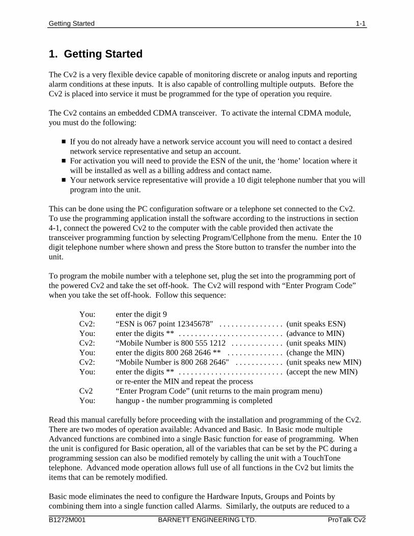
1. Getting Started
The Cv2 is a very flexible device capable of monitoring discrete or analog inputs and reportingalarm conditions at these inputs. It is also capable of controlling multiple outputs. Before theCv2 is placed into service it must be programmed for the type of operation you require.
The Cv2 contains an embedded CDMA transceiver. To activate the internal CDMA module,you must do the following:
# If you do not already have a network service account you will need to contact a desirednetwork service representative and setup an account.
# For activation you will need to provide the ESN of the unit, the ‘home’ location where itwill be installed as well as a billing address and contact name.
# Your network service representative will provide a 10 digit telephone number that you willprogram into the unit.
This can be done using the PC configuration software or a telephone set connected to the Cv2. To use the programming application install the software according to the instructions in section4-1, connect the powered Cv2 to the computer with the cable provided then activate thetransceiver programming function by selecting Program/Cellphone from the menu. Enter the 10digit telephone number where shown and press the Store button to transfer the number into theunit.
To program the mobile number with a telephone set, plug the set into the programming port ofthe powered Cv2 and take the set off-hook. The Cv2 will respond with “Enter Program Code”when you take the set off-hook. Follow this sequence:
You: enter the digit 9Cv2: “ESN is 067 point 12345678" . . . . . . . . . . . . . . . . (unit speaks ESN)You: enter the digits ** . . . . . . . . . . . . . . . . . . . . . . . . . . (advance to MIN)Cv2: “Mobile Number is 800 555 1212 . . . . . . . . . . . . . (unit speaks MIN)You: enter the digits 800 268 2646 ** . . . . . . . . . . . . . .(change the MIN)Cv2: “Mobile Number is 800 268 2646" . . . . . . . . . . . . (unit speaks new MIN)You: enter the digits ** . . . . . . . . . . . . . . . . . . . . . . . . . . (accept the new MIN)
or re-enter the MIN and repeat the processCv2 “Enter Program Code” (unit returns to the main program menu)You: hangup - the number programming is completed
Read this manual carefully before proceeding with the installation and programming of the Cv2. There are two modes of operation available: Advanced and Basic. In Basic mode multipleAdvanced functions are combined into a single Basic function for ease of programming. Whenthe unit is configured for Basic operation, all of the variables that can be set by the PC during aprogramming session can also be modified remotely by calling the unit with a TouchTonetelephone. Advanced mode operation allows full use of all functions in the Cv2 but limits theitems that can be remotely modified.
Basic mode eliminates the need to configure the Hardware Inputs, Groups and Points bycombining them into a single function called Alarms. Similarly, the outputs are reduced to a
Getting Started 1-2
B1272M001 BARNETT ENGINEERING LTD. ProTalk Cv2
single function called Controls. The number of directories is reduced from 6 to 2 in Basic mode. It is possible to retain the Advanced directory commands even if the overall programming is setfor Basic operation.
It is important to establish whether Basic or Advanced programming is suitable for yourapplication. The mode is set by the configuration uploaded from the PC and cannot be alteredusing the programming phone. It is possible to switch programming modes during the PCprogramming session. When changing from Basic to Advanced there is no loss of data so it ispossible to quickly setup a unit in Basic mode then switch to Advanced to add some extrafunctions. Keep in mind that remote programming capabilities are very limited in Advancedmode. Changing from Advanced to Basic mode will destroy all of the programming informationexcept the directories which have the option of remaining in Advanced mode.
All of the telephone numbers that are entered into a directory should be carefully checked toensure that they are valid numbers. After the Cv2 has been programmed, a test should beperformed to confirm that these numbers are called correctly. The Cv2 has built-in networkprotection that will alter the operation of the Cv2 if invalid numbers are called.
To prevent excessive failed calls on the cellular network, the Cv2 has a built-in method forcounting unacknowledged calls. This process works by counting the number of unacknowledgedcalls that have been made and then taking action to alert the user that a large number of failuresare taking place. If the problem is not corrected and the Cv2 continues to place failed calls it willeventually stop calling.
Rules for this process are:
The number of unacknowledged calls is counted for each directory; receipt of anacknowledgment resets the counter. A retry on the same number is not counted.
If the counter exceeds 50 a “directory alarm” is created. This alarm is not latched and will becleared when an acknowledgment is received.
This “directory alarm” appears as a new alarm in all groups causing each group to call out andnotify the user that the alarm is present. This alarm is announced before the Site ID by speaking“Directory X Error” where X is the directory that has failed to be acknowledged for at least 50call out cycles.
If an interrogate code is received, the “Directory X Error” message will be made before anygroup alarms.
If the total number of unacknowledged calls in all directories exceeds 75, a call will be made toBarnett Engineering with the MIN and ESN of the phone. This information will be used toattempt to locate the owner of the equipment and notify them of the problem condition. At thispoint the timer used to control the interval between the last call in the directory and when thecycle is restarted at the first number will be set to 4 hours regardless of the program settings.
If the total number of unacknowledged calls exceeds 100, the Cv2 will cease to call out. TheCv2 will still answer incoming calls and reset the counters if an acknowledge code is received.
Each chapter has separate sections for Basic and Advanced operations. Once the mode that youwant to operate in has been established, use the applicable section in each chapter.
A comparison or the functions available for each mode is shown in Table 1.
Getting Started 1-3
B1272M001 BARNETT ENGINEERING LTD. ProTalk Cv2
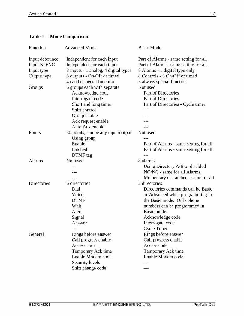
Table 1 Mode Comparison
Function Advanced Mode Basic Mode
Input debounce Independent for each input Part of Alarms - same setting for allInput NO/NC Independent for each input Part of Alarms - same setting for allInput type 8 inputs - 1 analog, 4 digital types 8 Alarms - 1 digital type onlyOutput type 8 outputs - On/Off or timed 8 Controls - 3 On/Off or timed
4 can be special function 5 always special functionGroups 6 groups each with separate Not used
Acknowledge code Part of Directories Interrogate code Part of Directories Short and long timer Part of Directories - Cycle timerShift control ---Group enable ---Ack request enable ---Auto Ack enable ---
Points 30 points, can be any input/output Not usedUsing group ---Enable Part of Alarms - same setting for allLatched Part of Alarms - same setting for allDTMF tag ---
Alarms Not used 8 alarms--- Using Directory A/B or disabled--- NO/NC - same for all Alarms--- Momentary or Latched - same for all
Directories 6 directories 2 directoriesDial Directories commands can be BasicVoice or Advanced when programming inDTMF the Basic mode. Only phone Wait numbers can be programmed inAlert Basic mode.Signal Acknowledge codeAnswer Interrogate code--- Cycle Timer
General Rings before answer Rings before answerCall progress enable Call progress enableAccess code Access codeTemporary Ack time Temporary Ack timeEnable Modem code Enable Modem codeSecurity levels —Shift change code —
Operations Overview 2-1
B1272M001 BARNETT ENGINEERING LTD. ProTalk Cv2
2. Operations Overview The purpose of this chapter is to provide an overview of the Cv2 capabilities. Chapter topics areorganized in the same order that you would follow in setting up the system. For more details on configuring the operation through the programming software, refer toChapter 3, Configuration.
2.1 Cv2 Capabilities (Advanced mode)
When an alarm occurs, the Cv2 places a call using its built-in cellular phone and announcesthe alarm condition using stored voice messages. Alarm messages consist of the site IDphrase, the group phrase and the alarm message phrase that are stored at voice programmingtime. The group phrase is used if the alarms have been grouped to provide different activitiesfor different alarm conditions. The unit can also be called up and interrogated to obtaincurrent alarm conditions and readings.
The Cv2 has eight hardware inputs that can be programmed to accept either digital or analogsignals and eight hardware outputs. Inputs can be independently configured to operate inthese modes:
digital monitoring contact closures or voltage levels
watchdog monitoring for the absence of a periodic event
totalizer counting events
interval measuring the time duration of events
analog measuring 0 to 5 volt signals
Outputs can be set to operate as either on/off controls or as timed controls.
2.1.2 What constitutes an alarm?
Alarm conditions can be defined for digital, watchdog and analog inputs. Totalizers andinterval inputs are used for measurement purposes and do not generate alarms. The signal atthe input is conditioned by a debounce timer that ensures the level is valid before accepting it.
A digital input has normal and alarm states that can be defined as either when the input is highor low. After the input signal has been qualified by the debounce timer, it can be registered asan alarm when the input is active, or it can be latched to detect a pulsed condition. The voicemessage for a digital input is programmed to announce the alarm condition that it ismonitoring, e.g. “Intrusion Alarm”.
Watchdog inputs use a timer that is restarted by changes at the input. If this timer expiresbecause it has not been restarted within the programmed interval, an alarm will register. Likethe digital input, the watchdog can be set as either an active-only or latched alarm. The voicemessage for a watchdog is similar to a digital, e.g. “Tower Strobe Failure”.
Analog inputs convert the voltage level to a digital value and perform a comparison againstthe programmed low and high setpoints. An alarm is present when the measured value isabove or below the setpoint. Alarm messages are spoken using the stored phrase with either
Operations Overview 2-2
B1272M001 BARNETT ENGINEERING LTD. ProTalk Cv2
HARDWAREINPUTS
8INPUTS
8OUTPUTS
POINTSUP TO 30 INPUTS OR OUTPUTS
GROUP1
CELL PHONE
HARDWAREOUTPUTS
GROUP6
DIRECTORYA
DIRECTORYF
DIALOUTCOMMANDS
CONTROLCOMMANDS
Figure 1Cv2 Block Diagram - Advanced Mode
“High” or Low” appended depending on which setpoint has been exceeded. The actualreading, including decimal place notation and engineering units, is spoken when the Cv2 isinterrogated.
The latching alarm function is also available for analog inputs.
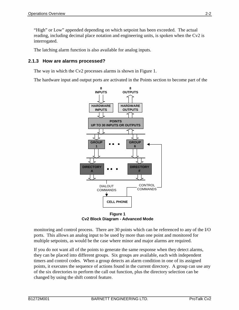
2.1.3 How are alarms processed?
The way in which the Cv2 processes alarms is shown in Figure 1.
The hardware input and output ports are activated in the Points section to become part of the
monitoring and control process. There are 30 points which can be referenced to any of the I/Oports. This allows an analog input to be used by more than one point and monitored formultiple setpoints, as would be the case where minor and major alarms are required.
If you do not want all of the points to generate the same response when they detect alarms,they can be placed into different groups. Six groups are available, each with independenttimers and control codes. When a group detects an alarm condition in one of its assignedpoints, it executes the sequence of actions found in the current directory. A group can use anyof the six directories to perform the call out function, plus the directory selection can bechanged by using the shift control feature.
Operations Overview 2-3
B1272M001 BARNETT ENGINEERING LTD. ProTalk Cv2
2.1.4 What actions should occur when an alarm is detected?
All alarm conditions will be processed by placing a call on the cellular phone. The callednumber and the activities that occur with different alarms are determined by entries in thedirectories. A directory contains the sequence of actions that will occur when a group has anactive alarm. Instructions for dialing, speaking, inserting delays and signaling are placed in thedirectory in the order in which they are to be performed. There are a total of six directories; eachcan contain a unique sequence of activities that will be performed when alarm conditions exist.
To best describe how a directory controls alarm reporting activities, an example directoryprogramming session follows. For more information on the directory summary and dialogbox, refer to Chapter 3. The opening window for a directory displays a summary of theactivities that it will perform when an alarm is detected. The directory summary is arrangedas lines; each line represents the sequence of events that will take place during one call out. Ifa Dial command is the first entry on the line, the Cv2 will call the programmed number andthen execute the remainder of the commands on that line. After the last command on the lineis competed, the call will be terminated. Commands such as Auto Ack and Wait, when usedas single line commands, do not initiate a call. For a basic sequence where the Cv2 is to call aphone number and speak the alarm message, the directory line contains the Dial and Voicecommands appearing as:
1. [DIAL]2458829 [VOICE]
This line will cause the Cv2 to place a call to 245-8829 and then speak the Site ID, GroupName and alarm message, or messages, for all active points. Unless programmed not to, theCv2 will append the phrase “Enter Acknowledge Code” at the end of the alarm announcementand wait for the code to be returned. If the code is received, the alarm sequence will beterminated until a new alarm occurs. Failure to receive an Acknowledge Code will advancethe sequence of operations to the next line in the directory. If the commands contained in thelast directory line have been completed without reception of an Acknowledge Code, the Cv2waits for the time interval set in the timers before repeating the process by starting over atdirectory line 1.
During execution of the Voice command, the Cv2 will try to announce the alarm messagesthree times with a one minute limit for the total announcement duration.
For example, to call four telephone numbers, the directory would appear as:
1. [DIAL]2458829 [VOICE]
2. [DIAL]2336700 [VOICE]
3. [DIAL]9842121 [VOICE]
4. [DIAL]9843316 [VOICE]
If you want an alert tone to precede the voice message the directory line would look like this:
1. [DIAL]2458829 [ALERT] [VOICE]
The next example shows a sequence that is used to call a numeric paging terminal. After thecall is placed there is a four second delay for the paging terminal to respond before the Cv2sends the number to be displayed on the pager. When calling a paging terminal, it issometimes useful to allow the called party time to call the Cv2 back and acknowledge the
Operations Overview 2-4
B1272M001 BARNETT ENGINEERING LTD. ProTalk Cv2
alarm before the Cv2 advances to the next line in the directory. This can be done by using theWait command on its own line; the entry below will cause a four minute delay before the nextline is executed.
1. [DIAL]2458829 [WAIT]4 [DTMF]4567 2. [WAIT]240
Directory lines can be added, removed, or modified and new lines can be inserted betweenexisting lines.
2.1.5 How do you want to respond to an alarm call?
After the Cv2 has finished speaking the alarm messages, it prompts the called party with thephrase “Enter Acknowledge Code” and then waits five seconds for the code to be returned. Ifthe code is received, it will terminate any further call out activities until a new alarm occurs;otherwise, it will proceed to the next line in the directory. There is a TemporaryAcknowledge Time that can be set in the General section that will override the operation ofthe Acknowledge Code. If the temporary time is set to a value other than Off, and thereceived Acknowledge Code has the digit # appended to it, the Cv2 will remain in theacknowledged state only for this time interval. After the timer has expired and if the alarmcondition still exists, the Cv2 will resume alarm reporting. This feature is used as a safetymeasure to ensure that an alarm cannot be acknowledged and then left unattended.
Each group has its own Acknowledge Code which only affects points that have been assignedto the group. Other groups with different Acknowledge Codes will continue alarm reportingif they do not receive their own code.
Using the Auto Ack command in a directory will cause the Cv2 to automatically acknowledgeany alarms that are in the group using the directory. This feature must also be enabled for thatgroup, since other groups of points may be using the same directory. Auto Ack must be onthe last line in a directory since any further commands will never be executed.
Another method of acknowledging the Cv2 is by activating the special function that allowshardware inputs to be used as local acknowledge controls.
2.1.6 What if an alarm is not acknowledged?
When the last line in the directory has been completed without receipt of an AcknowledgeCode, a two-stage timer is used to determine when the directory sequence is repeated again. This timer has two sections: a Short Timer which operates for the number set in Short Cycles,and a Long Timer which begins after the Short Timer has completed its cycles. This providesa means of varying the repetition cycle over a period of time.
2.1.7 What do you want the Cv2 to do when you call it?
In addition to reporting alarms, the Cv2 will also answer incoming calls. This allows you tointerrogate the unit, operate control outputs and change shifts. You can control the level ofsecurity that is presented to incoming calls. With the lowest level, the call will be answeredwith the Site ID phrase, the phrases for any groups that have alarms, followed by the prompt“Enter Command Code”. An Access Code is not required. At the next level of security, theCv2 will announce the Site ID phrase and then wait ten seconds for the password code before
Operations Overview 2-5
B1272M001 BARNETT ENGINEERING LTD. ProTalk Cv2
allowing access to alarm information or other control functions. At the highest level, the callis answered but there are no voice prompts; the caller has ten seconds to enter the AccessCode.
Each group of alarms has its own Interrogate Code. When the code is entered, the alarmstatus for points in that group is spoken. For digital and watchdog points, the stored phrasefor that point is spoken. Analog points are spoken with the stored phrase and its status -- high,low or normal -- followed by the reading. For totalizers, the stored phrase is spoken firstfollowed by the current accumulated value. Interval timers respond with the stored phrase andthe last captured interval.
Control outputs respond with the stored phrase followed by either ‘On’ or ‘Off’ indicatingtheir current state.
The presence of incoming calls is indicated by the ringing sound from the speaker and at oneof the outputs if it is selected to show ringing.
2.1.8 Sending remote control commands
Controls can be controlled using the programmed codes. These codes can be sent to the Cv2either during a reporting sequence or when a call is placed to the unit.
During the alarm reporting sequence, the control codes may be sent after the “EnterAcknowledge Code” prompt is heard. For the next five seconds, the Cv2 will acceptAcknowledge, Interrogate or Control codes. With each received code, the command will beperformed and a prompt for another command entry will then be spoken. For a remote controloutput, the status of the output will be spoken after the received code has been executed.
When the unit is called and after the Access Code, if required, has been entered, the prompt to“Enter Command Code” will be issued. In either case, the call will be terminated if a validcode is not received during the ten second window.
2.2 Cv2 Capabilities (Basic mode)
When an alarm occurs, the Cv2 places a call using its built-in cellular phone and announcesthe alarm condition using stored voice messages. Alarm messages consist of the site IDphrase and the alarm message phrase that are stored at voice programming time. The unit canalso be called up and interrogated to obtain current alarm conditions.
The Cv2 has eight alarm inputs that are programmed as conventional digital inputs, set aseither high or low to indicate an alarm.
The three user controls can be set to operate as either on/off controls or as timed controls. Theother five controls are always set to indicate New Alarm, Any Alarm, Acknowledge Received,Modem Carrier Detect and Ring Out.
Operations Overview 2-6
B1272M001 BARNETT ENGINEERING LTD. ProTalk Cv2
ALARMS
8INPUTS
8OUTPUTS
CELL PHONE
OUTPUTS
DIRECTORYA
DIRECTORYB
DIALOUTCOMMANDS
CONTROLCOMMANDS
5HARDWARE
CONTROLLED
3USER
CONTROLLED
ACKNOWLEDGEINTERROGATE
ACCESS
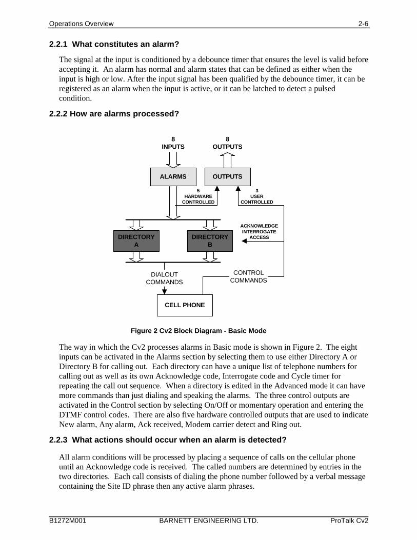
Figure 2 Cv2 Block Diagram - Basic Mode
2.2.1 What constitutes an alarm?
The signal at the input is conditioned by a debounce timer that ensures the level is valid beforeaccepting it. An alarm has normal and alarm states that can be defined as either when theinput is high or low. After the input signal has been qualified by the debounce timer, it can beregistered as an alarm when the input is active, or it can be latched to detect a pulsedcondition.
2.2.2 How are alarms processed?
The way in which the Cv2 processes alarms in Basic mode is shown in Figure 2. The eightinputs can be activated in the Alarms section by selecting them to use either Directory A orDirectory B for calling out. Each directory can have a unique list of telephone numbers forcalling out as well as its own Acknowledge code, Interrogate code and Cycle timer forrepeating the call out sequence. When a directory is edited in the Advanced mode it can havemore commands than just dialing and speaking the alarms. The three control outputs areactivated in the Control section by selecting On/Off or momentary operation and entering theDTMF control codes. There are also five hardware controlled outputs that are used to indicateNew alarm, Any alarm, Ack received, Modem carrier detect and Ring out.
2.2.3 What actions should occur when an alarm is detected?
All alarm conditions will be processed by placing a sequence of calls on the cellular phoneuntil an Acknowledge code is received. The called numbers are determined by entries in thetwo directories. Each call consists of dialing the phone number followed by a verbal messagecontaining the Site ID phrase then any active alarm phrases.
Operations Overview 2-7
B1272M001 BARNETT ENGINEERING LTD. ProTalk Cv2
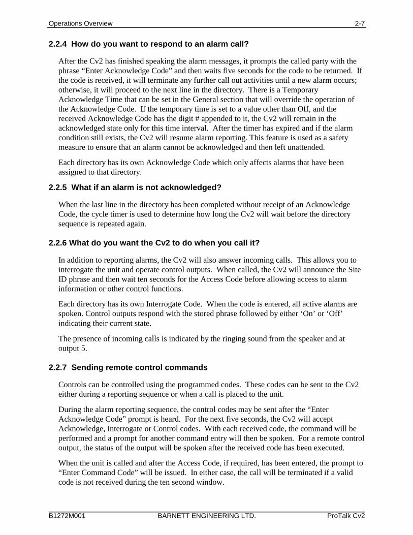
2.2.4 How do you want to respond to an alarm call?
After the Cv2 has finished speaking the alarm messages, it prompts the called party with thephrase “Enter Acknowledge Code” and then waits five seconds for the code to be returned. Ifthe code is received, it will terminate any further call out activities until a new alarm occurs;otherwise, it will proceed to the next line in the directory. There is a TemporaryAcknowledge Time that can be set in the General section that will override the operation ofthe Acknowledge Code. If the temporary time is set to a value other than Off, and thereceived Acknowledge Code has the digit # appended to it, the Cv2 will remain in theacknowledged state only for this time interval. After the timer has expired and if the alarmcondition still exists, the Cv2 will resume alarm reporting. This feature is used as a safetymeasure to ensure that an alarm cannot be acknowledged and then left unattended.
Each directory has its own Acknowledge Code which only affects alarms that have beenassigned to that directory.
2.2.5 What if an alarm is not acknowledged?
When the last line in the directory has been completed without receipt of an AcknowledgeCode, the cycle timer is used to determine how long the Cv2 will wait before the directorysequence is repeated again.
2.2.6 What do you want the Cv2 to do when you call it?
In addition to reporting alarms, the Cv2 will also answer incoming calls. This allows you tointerrogate the unit and operate control outputs. When called, the Cv2 will announce the SiteID phrase and then wait ten seconds for the Access Code before allowing access to alarminformation or other control functions.
Each directory has its own Interrogate Code. When the code is entered, all active alarms arespoken. Control outputs respond with the stored phrase followed by either ‘On’ or ‘Off’indicating their current state.
The presence of incoming calls is indicated by the ringing sound from the speaker and atoutput 5.
2.2.7 Sending remote control commands
Controls can be controlled using the programmed codes. These codes can be sent to the Cv2either during a reporting sequence or when a call is placed to the unit.
During the alarm reporting sequence, the control codes may be sent after the “EnterAcknowledge Code” prompt is heard. For the next five seconds, the Cv2 will acceptAcknowledge, Interrogate or Control codes. With each received code, the command will beperformed and a prompt for another command entry will then be spoken. For a remote controloutput, the status of the output will be spoken after the received code has been executed.
When the unit is called and after the Access Code, if required, has been entered, the prompt to“Enter Command Code” will be issued. In either case, the call will be terminated if a validcode is not received during the ten second window.
Operations Overview 2-8
B1272M001 BARNETT ENGINEERING LTD. ProTalk Cv2
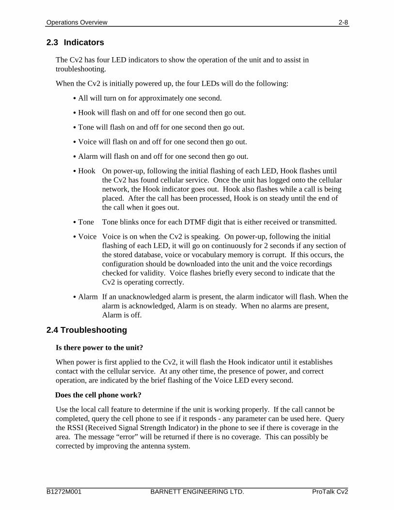
2.3 Indicators
The Cv2 has four LED indicators to show the operation of the unit and to assist introubleshooting.
When the Cv2 is initially powered up, the four LEDs will do the following:
C All will turn on for approximately one second.
C Hook will flash on and off for one second then go out.
C Tone will flash on and off for one second then go out.
C Voice will flash on and off for one second then go out.
C Alarm will flash on and off for one second then go out.
C Hook On power-up, following the initial flashing of each LED, Hook flashes untilthe Cv2 has found cellular service. Once the unit has logged onto the cellularnetwork, the Hook indicator goes out. Hook also flashes while a call is beingplaced. After the call has been processed, Hook is on steady until the end ofthe call when it goes out.
C Tone Tone blinks once for each DTMF digit that is either received or transmitted.
C Voice Voice is on when the Cv2 is speaking. On power-up, following the initialflashing of each LED, it will go on continuously for 2 seconds if any section ofthe stored database, voice or vocabulary memory is corrupt. If this occurs, theconfiguration should be downloaded into the unit and the voice recordingschecked for validity. Voice flashes briefly every second to indicate that theCv2 is operating correctly.
C Alarm If an unacknowledged alarm is present, the alarm indicator will flash. When thealarm is acknowledged, Alarm is on steady. When no alarms are present,Alarm is off.
2.4 Troubleshooting
Is there power to the unit?
When power is first applied to the Cv2, it will flash the Hook indicator until it establishescontact with the cellular service. At any other time, the presence of power, and correctoperation, are indicated by the brief flashing of the Voice LED every second.
Does the cell phone work?
Use the local call feature to determine if the unit is working properly. If the call cannot becompleted, query the cell phone to see if it responds - any parameter can be used here. Querythe RSSI (Received Signal Strength Indicator) in the phone to see if there is coverage in thearea. The message “error” will be returned if there is no coverage. This can possibly becorrected by improving the antenna system.
Operations Overview 2-9
B1272M001 BARNETT ENGINEERING LTD. ProTalk Cv2
Are the inputs connected properly?
For digital inputs that are programmed for standard digital operation, create an alarmcondition on the input and confirm that the Alarm LED comes on. Make sure the input isapplied long enough for the debounce to time out. If the Alarm indicator does not come on,the problem is not necessarily with the input connection. Check that the input is enabled as avalid point, the associated group is enabled, and the directory is programmed to call out..
For analog inputs (Advanced mode only), interrogate their group to hear the scaled value atthe input.
The unit does not dial out.
Check the Alarm LED to confirm that an alarm is present. If this indicator is not flashing, theCv2 will not call out. For Advanced mode programming, check that the input is enabled as avalid point, the associated group is enabled, and the directory is programmed to call out. ForBasic mode programming, check that the alarm has a valid directory selected.
I cannot call into the unit.
If you receive a recording from the telephone company indicating the user is not available,there may be a problem with the installation or you may be calling the wrong number. Usethe programming phone to confirm the telephone number in the unit.
Installation 3-1
B1272M001 BARNETT ENGINEERING LTD. ProTalk Cv2
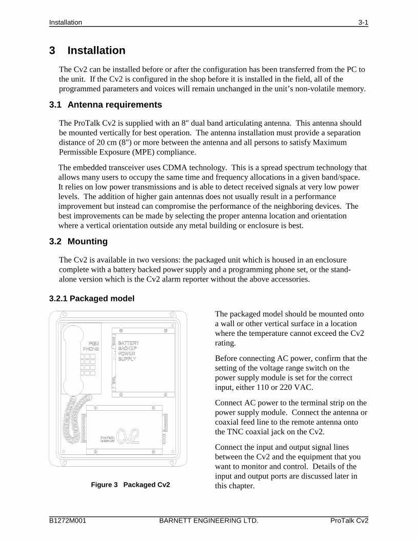
Figure 3 Packaged Cv2
3 Installation
The Cv2 can be installed before or after the configuration has been transferred from the PC tothe unit. If the Cv2 is configured in the shop before it is installed in the field, all of theprogrammed parameters and voices will remain unchanged in the unit’s non-volatile memory.
3.1 Antenna requirements
The ProTalk Cv2 is supplied with an 8" dual band articulating antenna. This antenna shouldbe mounted vertically for best operation. The antenna installation must provide a separationdistance of 20 cm (8") or more between the antenna and all persons to satisfy MaximumPermissible Exposure (MPE) compliance.
The embedded transceiver uses CDMA technology. This is a spread spectrum technology thatallows many users to occupy the same time and frequency allocations in a given band/space. It relies on low power transmissions and is able to detect received signals at very low powerlevels. The addition of higher gain antennas does not usually result in a performanceimprovement but instead can compromise the performance of the neighboring devices. Thebest improvements can be made by selecting the proper antenna location and orientationwhere a vertical orientation outside any metal building or enclosure is best.
3.2 Mounting
The Cv2 is available in two versions: the packaged unit which is housed in an enclosurecomplete with a battery backed power supply and a programming phone set, or the stand-alone version which is the Cv2 alarm reporter without the above accessories.
3.2.1 Packaged model
The packaged model should be mounted ontoa wall or other vertical surface in a locationwhere the temperature cannot exceed the Cv2rating.
Before connecting AC power, confirm that thesetting of the voltage range switch on thepower supply module is set for the correctinput, either 110 or 220 VAC.
Connect AC power to the terminal strip on thepower supply module. Connect the antenna orcoaxial feed line to the remote antenna ontothe TNC coaxial jack on the Cv2.
Connect the input and output signal linesbetween the Cv2 and the equipment that youwant to monitor and control. Details of theinput and output ports are discussed later inthis chapter.
Installation 3-2
B1272M001 BARNETT ENGINEERING LTD. ProTalk Cv2
Figure 4 Stand-alone Cv2
Figure 5 Ground Closure Input Wiring
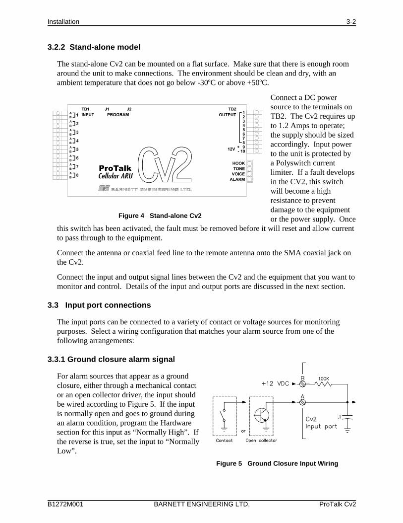
3.2.2 Stand-alone model
The stand-alone Cv2 can be mounted on a flat surface. Make sure that there is enough roomaround the unit to make connections. The environment should be clean and dry, with anambient temperature that does not go below -30oC or above +50oC.
Connect a DC powersource to the terminals onTB2. The Cv2 requires upto 1.2 Amps to operate;the supply should be sizedaccordingly. Input powerto the unit is protected bya Polyswitch currentlimiter. If a fault developsin the CV2, this switchwill become a highresistance to preventdamage to the equipmentor the power supply. Once
this switch has been activated, the fault must be removed before it will reset and allow currentto pass through to the equipment.
Connect the antenna or coaxial feed line to the remote antenna onto the SMA coaxial jack onthe Cv2.
Connect the input and output signal lines between the Cv2 and the equipment that you want tomonitor and control. Details of the input and output ports are discussed in the next section.
3.3 Input port connections
The input ports can be connected to a variety of contact or voltage sources for monitoringpurposes. Select a wiring configuration that matches your alarm source from one of thefollowing arrangements:
3.3.1 Ground closure alarm signal
For alarm sources that appear as a groundclosure, either through a mechanical contactor an open collector driver, the input shouldbe wired according to Figure 5. If the inputis normally open and goes to ground duringan alarm condition, program the Hardwaresection for this input as “Normally High”. Ifthe reverse is true, set the input to “NormallyLow”.
Installation 3-3
B1272M001 BARNETT ENGINEERING LTD. ProTalk Cv2
Figure 6 +12 Volt Input Wiring
Figure 7 +5 VDC Input Wiring
Figure 9 Analog (unfiltered) Input WiringFigure 8 Analog (filtered) Input Wiring
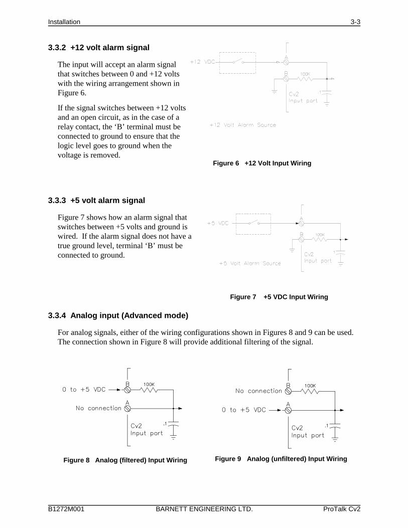
3.3.2 +12 volt alarm signal
The input will accept an alarm signalthat switches between 0 and +12 voltswith the wiring arrangement shown inFigure 6.
If the signal switches between +12 voltsand an open circuit, as in the case of arelay contact, the ‘B’ terminal must beconnected to ground to ensure that thelogic level goes to ground when thevoltage is removed.
3.3.3 +5 volt alarm signal
Figure 7 shows how an alarm signal thatswitches between +5 volts and ground iswired. If the alarm signal does not have atrue ground level, terminal ‘B’ must beconnected to ground.
3.3.4 Analog input (Advanced mode)
For analog signals, either of the wiring configurations shown in Figures 8 and 9 can be used. The connection shown in Figure 8 will provide additional filtering of the signal.
Installation 3-4
B1272M001 BARNETT ENGINEERING LTD. ProTalk Cv2
Figure 10 Output Wiring
Figure 11 Serial Cable
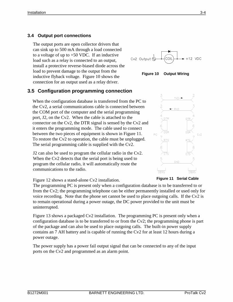
3.4 Output port connections
The output ports are open collector drivers thatcan sink up to 500 mA through a load connectedto a voltage of up to +50 VDC. If an inductiveload such as a relay is connected to an output,install a protective reverse-biased diode across theload to prevent damage to the output from theinductive flyback voltage. Figure 10 shows theconnection for an output used as a relay driver.
3.5 Configuration programming connection
When the configuration database is transferred from the PC tothe Cv2, a serial communications cable is connected betweenthe COM port of the computer and the serial programmingport, J2, on the Cv2. When the cable is attached to theconnector on the Cv2, the DTR signal is sensed by the Cv2 andit enters the programming mode. The cable used to connectbetween the two pieces of equipment is shown in Figure 11. To restore the Cv2 to operation, the cable must be unplugged. The serial programming cable is supplied with the Cv2.
J2 can also be used to program the cellular radio in the Cv2. When the Cv2 detects that the serial port is being used toprogram the cellular radio, it will automatically route thecommunications to the radio.
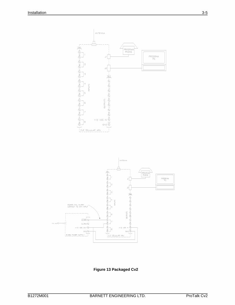
Figure 12 shows a stand-alone Cv2 installation. The programming PC is present only when a configuration database is to be transferred to orfrom the Cv2; the programming telephone can be either permanently installed or used only forvoice recording. Note that the phone set cannot be used to place outgoing calls. If the Cv2 isto remain operational during a power outage, the DC power provided to the unit must beuninterrupted.
Figure 13 shows a packaged Cv2 installation. The programming PC is present only when aconfiguration database is to be transferred to or from the Cv2; the programming phone is partof the package and can also be used to place outgoing calls. The built-in power supplycontains an 7 AH battery and is capable of running the Cv2 for at least 12 hours during apower outage.
The power supply has a power fail output signal that can be connected to any of the inputports on the Cv2 and programmed as an alarm point.
Installation 3-5
B1272M001 BARNETT ENGINEERING LTD. ProTalk Cv2
Figure 12 Stand-alone Cv2
Figure 13 Packaged Cv2
Configuration using the PC 4-1
B1272M001 BARNETT ENGINEERING LTD. ProTalk Cv2
4 Configuration using the PC
This chapter describes how to install the programming software and configure the operation ofthe Cv2. When the configuration is complete, it can be viewed through the Summarycommand found on the File pull-down menu. In the summary, Warnings should be checkedto ensure that there are no improper settings in the configuration before it is transferred to theCv2.
4.1 PC requirements
The minimum requirements for the PC used to run the Cv2 programming software are:
• 486 processor
• Windows 95
• 8M RAM
• SVGA screen
• Serial COM port
4.2 Installing the program
The CD supplied with the Cv2 contain the configuration software and the software installationutility. Place the CD into the drive and select the program SETUP.EXE using Run in thewindows Start menu. Follow the instructions and the installation program will automaticallyinstall the configuration program onto the hard drive.
4.3 Starting the configuration program
To start the program, click on the Cv2 icon that appears in the installed location. The programwill load and search for the default startup files:
Cv2.dat - the configuration database
Cv2.cfg - the serial port setting
If these files are not found, default files will be created and a warning posted.
4.4 How to access programming functions
At the top of the application are drop-down menus and buttons on the taskbar that launch thevarious operations in the program. The taskbar buttons duplicate the operations found in themenu. To activate on-line help, press F1 or select the Help menu at the top of the desktop.Context help for the controls is available when dialog boxes are open. Press the Helpquestion mark in the upper right of the dialog box, place the curser with the question markover the control, then click the left mouse button.
Selection items on the menus and taskbar are different for Advanced and Basic editing. Themenu and button operations for the two modes are summarized in the following section.
Configuration using the PC 4-2
B1272M001 BARNETT ENGINEERING LTD. ProTalk Cv2
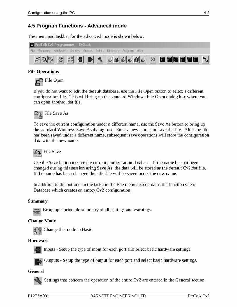
4.5 Program Functions - Advanced mode
The menu and taskbar for the advanced mode is shown below:
File Operations
File Open
If you do not want to edit the default database, use the File Open button to select a differentconfiguration file. This will bring up the standard Windows File Open dialog box where youcan open another .dat file.
File Save As
To save the current configuration under a different name, use the Save As button to bring upthe standard Windows Save As dialog box. Enter a new name and save the file. After the filehas been saved under a different name, subsequent save operations will store the configurationdata with the new name.
File Save
Use the Save button to save the current configuration database. If the name has not beenchanged during this session using Save As, the data will be stored as the default Cv2.dat file. If the name has been changed then the file will be saved under the new name.
In addition to the buttons on the taskbar, the File menu also contains the function ClearDatabase which creates an empty Cv2 configuration.
Summary
Bring up a printable summary of all settings and warnings.
Change Mode
Change the mode to Basic.
Hardware
Inputs - Setup the type of input for each port and select basic hardware settings.
Outputs - Setup the type of output for each port and select basic hardware settings.
General
Settings that concern the operation of the entire Cv2 are entered in the General section.
Configuration using the PC 4-3
B1272M001 BARNETT ENGINEERING LTD. ProTalk Cv2
GroupsEach of the six groups can be set to provide different alarm reporting operations forselected points.
PointsIn the points section, any of the hardware inputs and outputs can be selected for the Cv2to use as alarm reporting or remote control functions. There are 30 points available.
DirectoriesWhen an alarm is detected, the Cv2 will perform a specific sequence of eventsdetermined by the entries in the directory. Six directories are available, providingdifferent actions for different groups.
ProgrammingThe programming section is used to transfer the configuration database between the PCand the Cv2. Recorded voices can also be transferred from the Cv2 and then back.
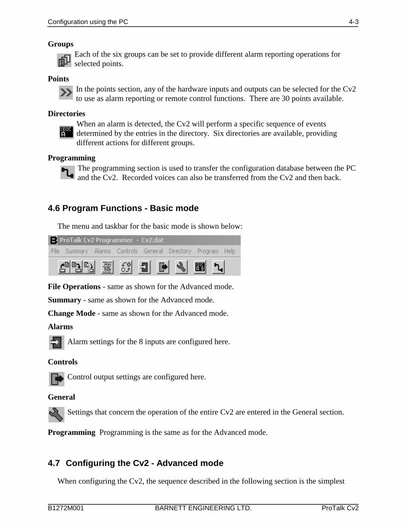
4.6 Program Functions - Basic mode
The menu and taskbar for the basic mode is shown below:
File Operations - same as shown for the Advanced mode.
Summary - same as shown for the Advanced mode.
Change Mode - same as shown for the Advanced mode.
Alarms
Alarm settings for the 8 inputs are configured here.
Controls
Control output settings are configured here.
General
Settings that concern the operation of the entire Cv2 are entered in the General section.
Programming Programming is the same as for the Advanced mode.
4.7 Configuring the Cv2 - Advanced mode
When configuring the Cv2, the sequence described in the following section is the simplest
Configuration using the PC 4-4
B1272M001 BARNETT ENGINEERING LTD. ProTalk Cv2
way to get the unit operational when in the Advanced mode. If the Cv2 uses any of the specialport functions -- Alarm Active, New Alarm, Acknowledge Received, Local Acknowledge orthe Totalizer Reset Input -- you must consider the relationship between these functions and theHardware, Groups and Points sections when configuring the unit.
4.7.1 Hardware section
Start with the Hardware section to establish settings for the input and output ports. Input portscan be configured as Digital, Analog, Watchdog, Totalizer or Interval types. Each port can beindependently set to one of these types; an individual port can have only one type assigned. Output ports can be either On/Off or Timed types.
To select an input for configuration click on the Hardware Inputs button to bring up thesummary of the input settings. Each of the eight inputs will be shown along with its currenttype and hardware settings. The input to be edited is highlighted and can be selected bypressing Enter, double-clicking on the line, or selecting the Edit Line function from themenubar. Selecting an input for editing will produce the dialog box for that input type.
After an input or output port has been configured, it can be activated in the Points section foralarm reporting, monitoring or control purposes. Input ports can be changed to one of theother types by selecting from the Change Input Port drop-down list. Changing the input typewill force any variables used in the Hardware section to the default value and will remove anypoints that make use of this port. Output ports can be changed from one type to the other.
Digital InputA Digital input represents the basic input type, responding to either high or low signals toindicate the status of the port. Wiring of the port determines if ground closure or voltagesignals are being monitored.
Debounce times are set to qualify the state of the input before it is considered valid. Twodebounce time ranges, seconds and minutes, are available. The seconds range has amaximum value of 1638 seconds (27 minutes) with a resolution of 25 msec. For longerdebounce times the minutes range should be used. When set to minutes, the debouncetimer has a maximum value of 65,535 minutes with a resolution of one minute. For shortdebounce times, use the seconds timer to avoid the inaccuracy introduced by the oneminute resolution.
Default Debounce time: 0.05 sec
A Digital input port can also be used to perform special functions in the Cv2. In theGroups section, it can be selected for the Local Acknowledge function, and in theHardware section it can be set to operate as a Reset Input for a Totalizer.
Watchdog InputA Watchdog timer is used to monitor periodic events and will produce an alarm if theevent does not occur within the programmed Watchdog interval. Each time an eventoccurs at the input, the timer is reloaded with the programmed value. When the timer hasexpired without a refresh event, the alarm is set. Refresh activities can be changes fromlow to high, changes from high to low, or both.
Watchdog input types use two timers for their operation: the Debounce timer and the
Configuration using the PC 4-5
B1272M001 BARNETT ENGINEERING LTD. ProTalk Cv2
Watchdog Interval timer. Refer to the preceding Digital input description for details on theDebounce timer. Two Watchdog time ranges, seconds and minutes, are available. Theseconds range has a maximum value of 1638 seconds (27 minutes) with a resolution of 25 msec. For longer Watchdog times the minutes range should be used. When set tominutes, the Watchdog timer has a maximum value of 65,535 minutes with a resolution ofone minute. For short Watchdog times, use the seconds timer to avoid the inaccuracyintroduced by the one minute resolution. When setting the two timers, take intoconsideration the relationship between the two. The Debounce time can not be greater thanthe Watchdog Interval; otherwise a constant alarm condition will occur.
Default Watchdog time: 10 min
Interval InputInterval timers measure the time interval that an input is active, either how long it is high orhow long it is low. The input is conditioned by the Debounce timer which is described inthe Digital input section. When setting the Debounce timer, consider the anticipatedduration of the interval. Since the Cv2 registers a change only after the Debounce time,long debounce settings will affect the accuracy of the measurement.
Totalizer InputTotalizer inputs measure the number of times that an event has occurred at the input. Theevent can be a high to low transition, a low to high transition, or both. Before the change isconsidered valid, it is conditioned by the Debounce timer - described in the Digital inputsection. Take into consideration the expected time period between events when setting theDebounce timer.
The count in the totalizer can be reset by two methods: by sending the Reset Code enteredin the Points section, or by using the Reset Input selection in the Hardware setup.
Analog InputSetting the input port type to Analog allows measurement of voltages between 0 and +5volts. As with the other input types, the definition of an analog input is completed in thePoints section where the range, setpoints and units are assigned.
An Analog port can be changed to one of the other input types by selecting from theChange Input Port drop-down list. Changing input type will force any variables used in theHardware section to the default value and will remove any points that make use of thisinput.
On/Off OutputOn/Off outputs operate with two DTMF codes that are set in the Points section. One codeturns the output On and the other returns it to the Off state. The output will remain in thelast commanded state indefinitely.
To make an On/Off port operational for remote control it must be configured and enabledin the Points section.
Timed OutputTimed outputs are activated by receipt of a single DTMF ‘On’ code. This code is set in thePoints section. When the code is received, the output will activate and will remain in thatstate until the timer expires or the DTMF ‘Off’ code is received.
Configuration using the PC 4-6
B1272M001 BARNETT ENGINEERING LTD. ProTalk Cv2
Two timer ranges, seconds and minutes, are available. The seconds range has a maximumvalue of 1638 seconds (27 minutes) with a resolution of 25 msec. For longer times theminutes range should be used. When set to minutes, the timer has a maximum value of65,535 minutes with a resolution of one minute. For short times use the seconds timer toavoid the inaccuracy introduced by the one minute resolution.
When the command to turn on the Timed output has been received and executed, the Cv2will announce the current state of the output port. If the timer value is set to a shortinterval, it is possible that the output will have returned to the Off state by the time thestatus is announced.
To make a Timed port operational for remote control it must be configured and enabled inthe Points section.
4.7.2 Points section
After the Hardware ports are configured, use the Points section to specify how activities onthese ports are processed. There are 30 points available for use as either input or outputcontrols. It is in the Points section that inputs are given the ability to generate alarms andoutputs are enabled to perform remote control functions. Each point can be referenced to anyof the input or output ports. When a port is selected in Points it will have the characteristicsthat were set in the Hardware section. If a different type of operation is required for a port, itmust be changed in the Hardware section.
Input and output ports that have been defined as a special function in the Group section (LocalAck New alarm, Any alarm or Ack received) or in the General section (Modem carrier detectand Ring out) are not available as general purpose ports.
To access a point for configuration, select the Points button to bring up the summary of thesettings. Status of the 30 points will be shown along with a brief description of their settings. Highlight the point to be edited, then select it by pressing Enter, double-clicking on the line,or choosing the Edit Line function from the menubar. Selecting a point will bring up thedialog box for that type.
Depending on the type of point, the contents of the dialog box will vary. There are a numberof common settings that appear in all of the point dialog boxes:
Common Settings for Points
I/O Port SelectionIf you would like to change the type of input or output, select one of the other availableports. Changing the port will force the point to its default settings and the settings forthe current point will be lost.
If a port is being used for one of the special functions, an abbreviated Function Codewill also be displayed in the port selection list. These are not available as points.
>ACK< Local acknowledge input for one or more groups.>RES< Reset input for one or more totalizers.<ALM> Output used to indicate there is an Alarm Active in one or more groups.<NEW> Output used to indicate that there is an unacknowledged, or New Alarm,
in one or more groups.<ACK> Output used to indicate that an Acknowledge Code has been received for
one or more groups.
Configuration using the PC 4-7
B1272M001 BARNETT ENGINEERING LTD. ProTalk Cv2
<RING> Output used to indicate that the phone is ringing.<CD> Output used to indicate that the modem is in the connected state.
Default Port Selection: Unused, not included in any reporting activities.
Point NameThe Point Name is a 16-character text field where you can enter a description of thepoint. This name is used for quick identification in the point summary; otherwise it isnot required for operation of the Cv2. Normally the name assigned is the same as thevoice message programmed into the Cv2 for this point.
Default Point name: empty text string.
Using GroupEach point is placed into a group, which will determine, through a directory, whatactions take place when an alarm occurs. For example, groups could be set up toprocess alarms specific to security, maintenance and/or operations. Points would thenbe assigned to the group concerned.
Default group: Group 1.
EnabledWhen a point is enabled, alarm activities will be reported and it can be interrogated forits current status. A disabled point does not produce alarms and cannot be interrogated. Changing the enable flag does not alter any of the other settings for this point.
Default Point state: disabled.
Digital and Watchdog PointsSettings for Watchdog points are the same as for Digital points.
Alarm StatePoints can be set to register an alarm in two ways: only when the alarm condition ispresent, or latched when an alarm condition is first detected. Latched operation meansthat the alarm is set when the input change is first detected and will remain in that stateuntil the group it is using is acknowledged. If the alarm is not latched, it will beremoved as an alarm when the input condition returns to normal.
Default alarm state: when active.
DTMF TagThe DTMF Tag is used to generate signaling messages for remote equipment. If aDTMF tag is available, it will be sent if the [SIGNAL] command is present in theDirectory.
The tag can consist of 1 to 7 digits and may use any of the 16 DTMF digits including A,B, C, and D.
Default DTMF Tag: empty string - no signaling.
Interval PointAn Interval Point uses only the common settings. It cannot generate alarms, but can beinterrogated to obtain readings.
Totalizer PointTotalizers cannot generate alarms, but can be interrogated to obtain readings. In additionto the common ones, the totalizer also has the these settings:
Configuration using the PC 4-8
B1272M001 BARNETT ENGINEERING LTD. ProTalk Cv2
Decimal PlaceA decimal place can be inserted into the spoken message for a totalizer. Five decimallocations are available:
XXXXX.XXXX.YXXX.YYXX.YYYX.YYYY
When the message is spoken, the digits to the left of the decimal (represented by X) andthe digits to the right of the decimal (represented by Y) are spoken with the word ‘point’between them. The format with the decimal at the far right with no ‘Y’ component isspoken without the word ‘point’.
Default Decimal Place: no decimal place spoken.
Clear CodeThe Clear Code is used to clear the totalizer to a zero reading. When the code isreceived, the Cv2 announces that the point has been cleared. The code can consist of 1to 7 digits and may use any of the 16 DTMF digits including A, B, C, and D.
Default Clear Code: empty string - no code.
UnitsIf you require the Cv2 to speak engineering units after the numeric value of theTotalizer, set them in the Units section. Units are subdivided into three components -- Prefix, Unit and Suffix -- as shown below:
Prefix Unit Suffix
NONE NONE NONETHOUSAND CUBIC METERS PER DAYMILLION CUBIC YARDS PER HOURMILLI CUBIC FEET PER MINUTECENTI PSI PER SECONDKILO POUNDSMEGA METERSGIGA RPM GALLON BARRELS
PERCENTPARTS PER MILLION
Select from the three columns to construct a phrase describing the units for the point. One, two or three of the selections can be used; if all are set to NONE then nothing willbe spoken after the numeric value.
Default Units: for all three sections is NONE.
Analog Point
Analog points generate alarms when the input value exceeds either the low or highsetpoints. Like Digital and Watchdog points, they have Alarm State and DTMF Tagsettings. The other settings in the Analog Point dialog box are unique to this type of point.
Calibrate
Calibration of an analog allows the conversion of the input voltage reading to a valuethat is expressed in engineering units. Setpoints are then assigned to the actualcorresponding measurement, and when the point is interrogated, the reading is
Configuration using the PC 4-9
B1272M001 BARNETT ENGINEERING LTD. ProTalk Cv2
announced in engineering units. Calibrate is a secondary dialog box that is activatedfrom the Analog Point dialog box.
The relationship between the binary reading from the input analog converter and thedecimal value that is used for setpoints and annunciation is established by setting theBinary and Decimal limits.
Binary Values
The full scale binary range, when an input port is configured for analog operation, isdetermined by the internal A to D converter which provides eight bits of resolution. The minimum binary value is 0 and the maximum value is 255 for the input range of0 to +5 VDC.
If the sensor that is driving the input port does not produce a full scale output thatcorresponds to the Cv2 range, then the binary values can be adjusted to match thesensor. For example, if a sensor with a full scale range of 1 volt to 5 volts is used,then set the Cv2 with the binary minimum at 51 (255 x 1/5) and the binary maximumat 255. If the sensor produces outputs of between 0 and 2.5 volts, then set the binaryminimum to 0 and the binary maximum to 127 (255 x 2.5/5).
The range of the sensor should use as much of the available Cv2 analog input rangeas possible in order to maintain a high resolution for the readings.
The minimum and maximum Binary values will correspond to the Decimalminimum and maximum that represent the actual readings, in engineering units,being monitored by the sensor.
Default Binary Values: 0 for the minimum and 255 for the maximum.
Decimal Values
Decimal values represent the real physical measurement being monitored by thesensor. For example, the current or voltage signals correspond to some engineeringvalue such as gallons or PSI.
Set the decimal minimum to the low end of the range being measured. Set thedecimal maximum to the high end of the sensor scale.
For example, if the minimum for the sensor is 50 rpm and maximum is 800 rpm,enter these values in the decimal section. Decimal values may be negative, e.g. atemperature range of -40oC to +60oC.
The range allowed for the decimal limits is -999.9 to +999.9. If values greater thanthese settings are needed, use a suitable prefix or suffix from Units and scale thereading to fit in the allowed range. If a sensor was connected to a meter with a rangeof 0 to 10,000 gallons per hour, then a suitable scale in the decimal values would be0 as the minimum, 10 as the maximum, with Units set to read ‘thousand’ as theprefix before gallons.
Once the range of the decimal scale has been entered, then the high and low setpointscan follow. Both setpoints can be used within a single point. If the low setpoint isnot required, set it to the decimal minimum; if the high setpoint is not needed, set itto the decimal maximum.
Default Decimal Values:
Configuration using the PC 4-10
B1272M001 BARNETT ENGINEERING LTD. ProTalk Cv2
Minimum: 0Maximum: +100.0Low Setpoint: +25.0High Setpoint: +75.0
HysteresisHysteresis is a quick method of establishing the reset values for the high and lowsetpoints. After an analog reading has exceeded the setpoint, either high or low, itmust pass through the reset value before it is considered to have returned to normal. This prevents a reading that is hovering around a setpoint from constantly going inand out of alarm. The more unstable the reading, the larger should be the hysteresis.
Hysteresis is calculated as a percentage of the decimal span and then used as anoffset from the setpoint. For the low setpoint, the reset will be above the setpoint andfor a high setpoint, the reset level will be below.
Default Hysteresis: 10% of decimal span.
UnitsIf you require engineering units to be announced after the numeric value of theAnalog Point, set them in the Units section. Available units are listed in the Points -Totalizer section.
On/Off Output Point
In addition to the common settings described previously, there are two DTMF controlcodes used with an On/Off output point.
DTMF On Code
When the Cv2 receives the DTMF On code, it sets the output port to the On state. Afterthe code has been received and the output port set, the Cv2 announces the current statusof the output.
This code can be 1 to 7 digits in length and may use any of the 16 DTMF digitsincluding A, B, C, and D.
Default DTMF On Code: an empty string - no On Code.
DTMF Off CodeWhen the Cv2 receives the DTMF Off code, it sets the output port to the Off state. After the Off code has been received and the output port cleared, the Cv2 announces thecurrent status of the output. This code can be 1 to 7 digits in length and may use any of the 16 DTMF digitsincluding A, B, C, and D. Default DTMF Off Code: an empty string - no Off Code.
Timed Output PointIn addition to the common settings, there are two DTMF control codes used with an Timedoutput point.
DTMF On CodeWhen the Cv2 receives the DTMF On code, it sets the output port to the On state andthe timer begins operation. After the On code has been received and the output port set,the Cv2 announces the current status of the output. If the timer is set for a short
Configuration using the PC 4-11
B1272M001 BARNETT ENGINEERING LTD. ProTalk Cv2
interval, the output port may have returned to the Off state before the announcement ismade.
This code can be 1 to 7 digits in length and may use any of the 16 DTMF digitsincluding A, B, C, and D.
Default DTMF On Code: an empty string - no On Code.
DTMF Off CodeWhen the Cv2 receives the DTMF Off code it sets the output port to the Off state andterminates the timer operation if it is currently running. The DTMF Off code will haveno effect if the output timer has already expired. After the Off code has been receivedand the output port cleared, the Cv2 announces the current status of the output.
This code can be 1 to 7 digits in length and may use any of the 16 DTMF digits.
Default DTMF Off Code: an empty string - no Off Code.
4.7.3 Group section
In some applications, there may be a requirement for different types of alarms to alert differentpeople. This is handled in the Cv2 by assigning alarms to different groups; there are sixgroups available for this purpose. Each alarm point has a selection list for setting the UsingGroup parameter. In the group dialog, the directory that it will be using is selected in the Shiftcontrol section. If the group activities are not going to be altered by changing shifts, use theshift 1 selection for all groups. If the use of directories by a group is going to change throughthe Shift Control, enter the appropriate directory into the shift selections.
Each Group has its own Acknowledge Code, Interrogate Code and Timer settings. Activitiesfor a particular group are performed according to the Shift that is selected. Each shift uses oneof the directories as the instruction source for the sequence of actions that occur during alarmconditions. If a different type of activity is required, such as after hours or weekends, thechange can be quickly made by using another shift to control the Cv2 operation. There arealso a number of special function settings that enable outputs and inputs to operate as controlsand indicators for some internal Cv2 activities.
The settings that can be entered for each group are defined below:
Group NameThe Group Name is a 16-character text field where you may enter a description of thegroup. The name is used only for identification purposes; otherwise it is not required foroperation of the Cv2. Normally the name is the same as the voice message programmedinto the Cv2 for this group.
Default Group Name: an empty text string.
Acknowledge CodeThe Acknowledge Code is a 1 to 7 digit DTMF string that is used to acknowledge thegroup and stop alarm transmission until a new alarm is detected. Each group can have aunique Acknowledge Code, or different groups can use the same code in order to beacknowledged simultaneously. In special cases where it is not desirable to have theAcknowledge Code permanently silence the alarm condition, append the digit ‘#’ whenyou send the code and the Temporary Acknowledge Time in the General section will beused as an override.
Default Acknowledge Code: an empty text string.
Configuration using the PC 4-12
B1272M001 BARNETT ENGINEERING LTD. ProTalk Cv2
Interrogate CodeThe Interrogate Code is a 1 to 7 digit DTMF string that is used to make the Cv2 announcethe condition of points in the group. Each group can have a unique Interrogate Code, ordifferent groups can use the same code in order to generate the status of all groups at once.
Default Interrogate Code: an empty text string.
Enable This GroupTo allow this group to be used for alarm reporting, this setting must be enabled. Points thatare used for ‘interrogate only’ have this setting turned off. Groups may also be enabled ordisabled via the local (or remote) programming phone.
Default Group Enable: disabled
Enable Auto AckIf the Auto Ack function is used as a Directory command, it must enabled here for it to bevalid for this group.
Default Auto Ack: disabled
Enable Ack RequestAt the completion of an alarm announcement sequence, the Cv2 will query the called partywith the phrase “Enter Acknowledge Code’. If this prompt is not required, clear the enablesetting.
Default Ack Request: enabled
TimersThe Cv2 uses a two-stage timer to schedule the interval between reporting sequences. Thefirst stage is controlled by the Short Timer interval which will repeat for the number oftimes set in Short Cycles before moving to the Long Timer. Once the Cv2 has reached theLong Timer stage it will continue to use this timer until a new alarm occurs.
Short TimerThe Short Timer can be set to any value between 0 and 255 minutes.Default Short Timer: 5 min.
Short CyclesThe maximum number of short cycles is 9.Default Short Cycles: 4
Long TimerThe Long Timer can be set to any value between 0 and 255 minutes.Default Long Timer: 30 min.
Shift SelectionThere are four shifts that can be used to alter the way that the Cv2 reports alarms. Thegroup will use the currently active shift to select a directory for its operations. The shift inuse at any particular time is determined by the last time that a Shift Change Code messagewas received. The Cv2 retains the current shift when it is powered down and will return tothat shift when power is restored. Each time a Shift Change Code is received, the shiftadvances by one; if the Cv2 is currently set to shift 4 and the Shift Change Code isreceived, it will go to the shift 1 setting. After receipt of the Shift Change Code, the Cv2responds with a spoken message indicating the new shift setting. The Shift Change Code isset in the General section.
Configuration using the PC 4-13
B1272M001 BARNETT ENGINEERING LTD. ProTalk Cv2
This code can be 1 to 7 digits in length and may use any of the 16 DTMF digits includingA, B, C, and D.
Default Shift Selection: Directory A for all shifts.
Special Function OutputsOutputs can be assigned to indicate certain conditions within the Cv2. The three specialfunction outputs are:
Alarm ActiveThis control allows any one of the eight output ports to be used as an indicator thatan alarm is present in this group. The selected output will remain active while analarm is present, acknowledged or not.
New AlarmThis control allows any one of the eight output ports to be used as an indicator thatan unacknowledged alarm (New Alarm) is present in this group. The selected outputwill remain active until the group is acknowledged or all new alarms are removed.
Acknowledge ReceivedThis control allows any one of the eight output ports to be used as an indicator thatan Acknowledge Code has been received for this group. The output selected for thisfunction should be set as a timed output port in the Hardware section. When anAcknowledge Code is received, the output will turn on and will remain on for thetimed interval.
If the Cv2 is using more than one group, special function outputs of the same typecan be assigned to the same output port in each group to provide a commonindicator, or different groups can use different outputs in order to distinguishbetween the groups. Each output that is selected for either Alarm Active, NewAlarm or Acknowledge Received can be used only for that one function. An outputcannot be shared between two of these functions.
If the output selected for one of these functions is currently in use as a remote controlpoint, the point will be removed.
Default Special Function Output: NONE.
Special Function Input - Acknowledge InThis special function can be used to designate one of the input ports as a localacknowledge for this group. When the specified input is active, the group will beacknowledged as though it had received a DTMF Acknowledge Code. If more than onegroup is being used, this setting can be the same port to create a common acknowledge,or different inputs can be selected to provide unique acknowledge controls.
Only Digital inputs can be used for this purpose. The selection shown in the list box isrestricted to inputs that are set to digital in the Hardware section.
Default Special Function Input: NONE.
4.7.4 DirectoriesThe Directories contain the sequences of actions that will occur when an alarm is activated ina group. Instructions for dialing, speaking, inserting delays and signaling are placed in thedirectory in the order in which they are to be performed. Each of the six directories cancontain unique operational sequences. The directory summary displays the sequence of events
Configuration using the PC 4-14
B1272M001 BARNETT ENGINEERING LTD. ProTalk Cv2
in a line-by-line format. A line represents one complete action, usually a cellular call. Editthe highlighted line by pressing Enter, double-clicking on the line, or selecting the Edit Linecommand from the menubar in the summary window. Lines can also be removed or inserted.
The editor dialog box displays two columns on the left, one for the Command entry and theother for the Value entry, if any. Buttons for each type of command are arranged on the right. Commands are entered when you click on the buttons on the right side of the dialog box. Thecommand appears at the location currently selected -- shown by an active option button. If thecommand has an associated Value such as a telephone number or waiting interval, then thevalue field to the right of the command will be accessible for data entry. Commands can beadded at the end of the list or inserted into the middle of the list.
The commands and their functions are:
DialThe Dial command is the first command entry. Associated with the Dial command is atelephone number that is entered in the Value field; this is the number that will be calledwhen an alarm condition is detected. The maximum length of the telephone number is 39digits. The special character ‘!’ can be inserted anywhere in the telephone number to createa two second delay in the dialing sequence.
When this command is encountered in the directory, the Cv2 initiates a call out on thecellular network and then maintains the call until the last command in the line is executed.
Dial can only appear as the first entry in the list.
Default Dial value: 0000
WaitThe Wait command is used to insert delays into the sequence. Associated with the Waitcommand is the time delay in seconds; range of the delay is from 0 to 255 seconds.
Wait can be a single entry on a line but if it is entered in a line with other commands it mustbe preceded by a Dial command.
Default Wait value: 0000
Auto AckIf enabled for the group using this directory, the Auto Ack command causes the Cv2 toautomatically acknowledge its alarms without receipt of any other code or signal. Thiscommand is used when it is anticipated that the called party will have no means ofacknowledging the call. Unless absolutely necessary, this command should not be usedsince there is no assurance that the alarm message was properly received.
The Auto Ack command should be the last entry in the directory and must appear on a lineby itself.
DTMFThe DTMF command will result in the string of DTMF digits in the associated Value fieldbeing transmitted. The maximum length of the DTMF string is 39 characters and thecharacters can be any of the 16 digits including A, B, C, and D. The special character ‘!’can be inserted anywhere in the DTMF string to create a two second delay.
DTMF must be preceded by a Dial command; it cannot be the first entry in the list. It canbe used more than once in a list.
Default DTMF value: 0000
Configuration using the PC 4-15
B1272M001 BARNETT ENGINEERING LTD. ProTalk Cv2
separated by 100 msec of quiet.
Alert must be preceded by a Dial command; it cannot be the first entry in the list. It can beused more than once in a list.
VoiceThe Voice command causes stored voice messages for the Site ID, Group IDs and anypoints in the alarm state to be spoken. If Voice is the only command after Dial, the Cv2will speak the alarm message three times or for one minute, whichever comes first.
Voice must be preceded by a Dial command; it cannot be the first entry in the list. It can beused only once in a list.
AnswerThe Answer command causes the Cv2 to monitor the called line for activity before it beginsto speak the alarm message. If the Cv2 is calling a voice or numeric paging terminal withan automated attendant, the Answer command will cause it to wait for the voice promptbefore transmitting the pager number. Do not place the Answer command immediatelyafter a Dial command if Call Progress is selected in the General section. This will causethe Cv2 to look for a voice response twice in a row and may prevent alarm announcements.
SignalIf a DTMF tag is programmed for a point and the Signal command is set, then only theDTMF tag for this point will be sent and the voice message will not be spoken.
Signal must be preceded by a Dial command; it cannot be the first entry in the list. It canbe used once in a list.
DeleteDelete removes the selected command from the list. Commands that followed the deletedone are moved to fill in the empty space. If the first command is selected, then Delete willremove all commands for this line.
4.7.5 General
Settings that affect the overall operation of the Cv2 are entered in the General section.
Site NameThe Site Name is a 16 character text field that allows you to enter a description of the sitewhere the Cv2 is to be located. Other than viewing in the General dialog box, this namehas no other use. Normally it is set to match the voice message that is programmed as theSite Identifier.
Default Site Name: an empty text string.
Security LevelThe Security level setting determines the actions that the Cv2 will perform when it receivesan incoming call.
Level 1 The Cv2 announces the Site ID, any groups that are in the alarm state andprompts the caller to “Enter Command Code”. An Access Code is notrequired.
Level 2 When the incoming call is answered by the Cv2, only the Site ID isannounced; for further access to the Cv2 the caller must enter the AccessCode.
Configuration using the PC 4-16
B1272M001 BARNETT ENGINEERING LTD. ProTalk Cv2
Level 2 When the incoming call is answered by the Cv2, only the Site ID isannounced; for further access to the Cv2 the caller must enter the AccessCode.
Level 3 An incoming call results in the Cv2 coming off-hook with noannouncement; the Access Code must be entered within ten seconds or theCv2 will hang up.
Default Security Level: Level 1
Access Code
An Access Code is needed when calling into a unit configured for security levels 2 or 3.
If the Access Code is empty, all incoming callers will be permitted access to theprogram mode. If a code is programmed, it must be entered for remote programmingotherwise the incoming call will be terminated. Local programming is alwaysaccessible.
This code can be 1 to 7 digits in length and may use any of the 16 DTMF digitsincluding A, B, C, and D.
Default Access Code: an empty string.
Shift Change CodeThe shift that is being used at any particular time is determined by the last time that a ShiftChange Code message was received. The Cv2 retains the current shift when it is powereddown and returns to that shift when power is restored. Each time a Shift Change Code isreceived, the shift advances by one. If the Cv2 is currently set to shift 4 and the changecode is received, it will go to the shift 1 setting.
This code can be 1 to 7 digits in length and may use any of the 16 DTMF digits includingA, B, C, and D.
Default Shift Change Code: an empty string.
Temporary Acknowledge TimeTemporary Acknowledge time is used as a safeguard with the Acknowledge Code. Whenthe Temporary Acknowledge Time is set to Off it has no effect on Cv2 operations. Normally, receipt of the Acknowledge Code for a group will cause that group to ceasealarm reporting activities until a new alarm is detected. When this control is set to any ofthe four available times (30, 60, 120 and 240 minutes), receipt of the Acknowledge Code,with the digit ‘#’ appended to it, will cause the alarm activities to cease only for the timeperiod set by the Temporary Time. After this timer expires, if the alarm condition has notbeen removed, the Cv2 will continue alarm functions as though the Acknowledge Code hadnot been received.
Default Temporary Acknowledge Time: Off
Call ProgressWhen Call Progress is enabled, the Cv2 will wait for the called party to speak beforebeginning the voice announcement. When Call Progress is enabled, there should not beany Answer commands directly following a Dial command in the directories. This willcause the Cv2 to look for a voice response twice in a row and may prevent alarmannouncements.
Default Call Progress: disabled
Configuration using the PC 4-17
B1272M001 BARNETT ENGINEERING LTD. ProTalk Cv2
Ring OutputRing output is used to select one of the eight outputs to externally indicate that there is anincoming call. The output will follow the ringing cadence if selected.
Default Ring Output: None
Modem CDModem Carrier Detect is used to select one of the eight outputs to externally indicate thatthe modem has connected to an incoming call. This function is activated by the ModemEnable Code and is only asserted during the connection and not for the timer interval
Default Modem CD: None
Enable Modem CodeThis code is required to allow the Cv2 to receive incoming over-the-air modem calls. Normally the Cv2 is in voice mode; following receipt of the Enable Modem code it willwait for a modem call for the time period set for the Modem CD in Hardware outputs.When this timer period has passed without a connection, the Cv2 returns to voice mode. Ifa connection is made, the Cv2 waits 30 seconds after the end of the modem session beforereturning to voice.
Default Enable Modem Code: empty string
Rings before AnswerRings before answer determines how may ring cycles the Cv2 will wait before answeringthe call.
Default Rings before Answer: Two
4.7.6 Configuration Programming
Three types of data can be transferred between the Cv2 and the programming PC. Programming can be done locally with the programming cable or remotely using the modemin the PC to call the Cv2 over-the-air. If remote programming is to be used, the Cv2 must beconfigured for a Enable Modem code and a Modem CD output enabled in the General section. The selected output is configured in Hardware for the time interval that the Cv2 will wait for amodem connection.
The programming dialog defaults to local operation when it opens. Press the Use Modembutton for remote programming.
For local programming the programming cable must be connected between the PC and theCv2 before any data transfer is initiated. Select the correct COM port for the attached cable inthe Serial Port box.
While the serial cable is attached, the Cv2 will be in programming mode and will not beoperational.
For remote programming, press the Dial button to bring up the telephone number entry dialog. Enter the telephone number for the Cv2 including the prefix 1 and area code if necessary. Press Disconnect when the modem session is finished
Data is transferred in four-kilobyte packets at 9600 baud. The configuration database willtake two packets to transfer; the number of packets in a voice data transfer will varydepending on how many points are used and how long the messages are.
Configuration using the PC 4-18
B1272M001 BARNETT ENGINEERING LTD. ProTalk Cv2
Configuration DataTo transfer configuration data, use the two buttons in the Configuration box. Press theWrite To Cv2 button to transmit the configuration database from the PC into the Cv2 orpress the Read From Cv2 button to transfer the configuration from the Cv2 to the PC .
Voice MessagesTo transfer voice data, use the buttons in the Voice box. Press the Write to Cv2 button tomove voice messages from a file in the PC to the Cv2. The recorded messages in the Cv2can be read and stored to a file by pressing the Read From Cv2 button. At the end of eachvoice programming session, it is advisable to read the voice information in the Cv2 andstore it to file.
VocabularyIf the stored vocabulary section in the Cv2 memory is corrupt it will be necessary totransfer the vocabulary from the PC to the Cv2. The most common symptom associatedwith a corrupt vocabulary is the absence of the female voice prompts during operation andprogramming. If problems are experienced with any of the voice operations the vocabularyshould be replaced. This is done by pressing the Write Vocabulary button to transmit thevocabulary data to the Cv2.
Writing the vocabulary to the Cv2 will delete all of the user stored messages. If thesemessages were previously saved to a file they can be transferred after the vocabulary is writteninto the Cv2, otherwise they will have to be recorded again.
4.8 Configuring the Cv2 - Basic mode
When configuring the Cv2 in Basic mode the easiest way to set the unit up is by running theBasic Wizard which will step you through all of the required entries. All of the variablespresented in the wizard are also accessible using the menus and taskbar.
4.8.1 Alarms section
Use this section to establish how the input signals are conditioned to become alarms.
DirectoryAn active alarm can be set to use either Directory A or Directory B for making call out. Unused alarm inputs are set for disabled. Each alarm can select it own Directory setting.
Default: disabled
FormatAll alarm inputs have the same format setting. Four possible arrangements are available:
Normally High, Normally Low, Normally High - Latched and Normally Low - Latched
Latched alarms hold the alarm state even if the input returns to normal. The alarm iscleared when the Cv2 is acknowledged.
Default: Normally Low
DebounceIn order for a change of state to be considered valid, an input must remain in the samestate for the duration of the Debounce time. Each input has an independent debouncetimer but all timers use the same time value when they are reloaded.
The common timescale can be set for either seconds or minutes. Maximum values are65535 minutes and 1638 seconds.
Default: 1 second
Configuration using the PC 4-19
B1272M001 BARNETT ENGINEERING LTD. ProTalk Cv2
4.8.2 Control section
Use the Control section to configure the hardware outputs if the Cv2 is going to be used forremote control. Three of the control outputs are user programmable and can be individuallyset for either on/off or timed operation; five outputs are used for the special functions.
FormatEach control can be either an On/Off or a Timed type.
Default: disabled
DTMF On CodeWhen the Cv2 receives the DTMF On code, it sets the control to the On state and, if it isset as a timed type, starts the timer. After the On code has been received and the output isset, the Cv2 announces the current status of the control. If the timer is set for a shortinterval, the control may have returned to the Off state before the announcement is made.
This code can be 1 to 7 digits in length and may use any of the 16 DTMF digits includingA, B, C, and D.
Default DTMF On Code: an empty string - no On Code.
DTMF Off CodeWhen the Cv2 receives the DTMF Off code it sets the control to the Off state and, if it isset as a timed type, terminates the timer operation if it is currently running. The DTMFOff code will have no effect if the timer has already expired. After the Off code has beenreceived and the control is cleared, the Cv2 announces the current status of the control.
This code can be 1 to 7 digits in length and may use any of the 16 DTMF digits.
Default DTMF Off Code: an empty string - no Off Code.
IntervalEach of the four controls has an independent duration timer that can be set to have either aseconds or minutes timescale. Maximum values are 65535 minutes and 1638 seconds.
Default: 1 second
4.8.3 General
Settings that affect the overall operation of the Cv2 are entered in the General section.
Site Name - same as for Advanced mode
Rings to Answer - same as for Advanced mode
Temporary Ack Time - same as for Advanced mode
Enable Call Progress - same as for Advanced mode
Enable Modem Code - same as for Advanced mode
Access Code - same as for Advanced mode
4.8.4 Directories
A Basic Directory contains a list of telephone numbers that will be called and followed by avoice message when the Cv2 is in operation; each directory can contain a different list. Associated with each directory is a unique Acknowledge code, Interrogate code and Cycletimer.
If the requirements of the system you are setting up cannot be met with the basic phonenumber and voice commands in the directory, you can switch to the advanced editor while
Configuration using the PC 4-20
B1272M001 BARNETT ENGINEERING LTD. ProTalk Cv2
keeping the rest of the configuration in basic mode.
Insert - Insert a new phone number at the highlighted location
Delete - Delete the phone number at the highlighted location
Edit - Modify the phone number at the highlighted location
Advanced - View or edit the directory with the Advanced editor
Acknowledge Code
The Acknowledge Code is a 1 to 7 digit DTMF string that is used to acknowledge thedirectory and stop alarm transmission until a new alarm is detected. Each directory canhave a unique Acknowledge Code, or they can both use the same code in order to beacknowledged simultaneously. In special cases where it is not desirable to have theAcknowledge Code permanently silence the alarm condition, append the digit ‘#’ whenyou send the code and the Temporary Acknowledge Time in the General section will beused as an override.
Default Acknowledge Code: an empty text string.
Interrogate Code
The Interrogate Code is a 1 to 7 digit DTMF string that is used to make the Cv2 announcethe condition of alarms using the directory. Each directory can have a unique InterrogateCode or both directories can use the same code.
Default Interrogate Code: an empty text string.
Cycle Timer
When the end of a directory has been reached without receipt of an Acknowledge code, theCv2 waits for the time set in the Cycle timer before repeating the alarm transmissionsequence. This repetition will continue until the unit is acknowledged.
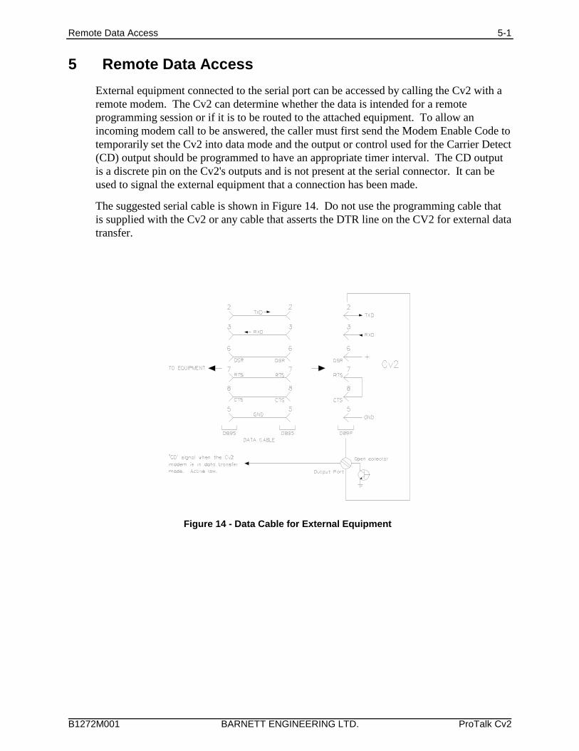
Remote Data Access 5-1
B1272M001 BARNETT ENGINEERING LTD. ProTalk Cv2
Figure 14 - Data Cable for External Equipment
5 Remote Data Access
External equipment connected to the serial port can be accessed by calling the Cv2 with aremote modem. The Cv2 can determine whether the data is intended for a remoteprogramming session or if it is to be routed to the attached equipment. To allow anincoming modem call to be answered, the caller must first send the Modem Enable Code totemporarily set the Cv2 into data mode and the output or control used for the Carrier Detect(CD) output should be programmed to have an appropriate timer interval. The CD outputis a discrete pin on the Cv2's outputs and is not present at the serial connector. It can beused to signal the external equipment that a connection has been made.
The suggested serial cable is shown in Figure 14. Do not use the programming cable thatis supplied with the Cv2 or any cable that asserts the DTR line on the CV2 for external datatransfer.
Voice Storage and Configuration with the Telset 6-1
B1272M001 BARNETT ENGINEERING LTD. ProTalk Cv2
6 Voice Storage and Configuration with the Telset
6.1 SetupThe Cv2 can be configured by transferring a database from the PC, either in Basic orAdvanced mode, or by using the programming phone. All of the variables in Basic modeare accessible through the telset; if the Cv2 has been programmed in Advanced mode onlythe following items are available:
Directory line editor
All voice phrases
Rings to answer, call progress enable, access code, modem enable code
Cell phone status
Outside line
For Advanced mode telset programming, ensure that the database in the unit is configuredproperly. The Cv2 must contain a valid database in order to determine which points haveassociated voice messages.
The usual method for voice programming is with a phone set plugged directly into the unit;however it is also possible to program voice messages remotely by calling the Cv2 over thenetwork.
If you are programming a stand-alone Cv2, a DTMF (TouchTone) telephone set is requiredto enter the voice messages. A rotary dial pulse telephone set will not work here. Connectthe phone set to port J1. If you have a package model, the phone set will already be in theenclosure.
In place of the Enter key or carriage return which you would use to enter data from akeyboard, the Cv2 interprets the characters rr as the Enter command. The programmingsequence is controlled by pressing a single digit followed by the rr digits. Ensure that nomore than one second separates the two r digits.
6.2 AccessTo begin a local programming session, lift the telephone handset to your ear. To performremote programming call the site from a remote telephone set.
The Cv2 has stored voice prompts to guide you through the programming mode. The firstmessage you will hear is “Enter Command Code.” At this time you can interrogate,acknowledge or control the unit. If the Access Code is entered, the prompt changes to“Enter Program Code” and all LEDs illuminate. The same action occurs if you are callingin remotely.
With the security level set to ‘1' with local programming, the Cv2 will advance to theprogram mode automatically after 5 seconds if an access code is not entered. An accesscode is needed for remote and local programming with security level settings 2 and 3.
6.3 Programming Commands
After the security requirements have been met, you can begin programming voices orchanging the configuration by entering one of the programming commands. The followingexample is for part of an advanced mode programming session. The sequences for bothBasic and Advanced modes are shown in detail at the end of this section.
Voice Storage and Configuration with the Telset 6-2
B1272M001 BARNETT ENGINEERING LTD. ProTalk Cv2
Directory programming, where the called numbers are entered, requires care to ensure thatthese numbers are valid. If the Cv2 is unable to successfully complete calls it will takeaction to ensure that the cellular network is not adversely affected. These actions aredetailed in the “Getting Started” section at the beginning of the manual.
The following example shows how to enter voice messages using a telephone set.
Cv2: “Enter Program Code”
1rr - Voices
Cv2: “Enter Voice Code”
After the Cv2 responds with this prompt it waits for you to enter a selection from thevoice menu. The choices at this point are:
1rr - Record or Play Back Site ID and Group Voices
Cv2: “Site ID is Ajax Compressor Station”
(The first time the site ID, or any other voice message, is programmed, the Cv2 willhave either no voice message or a factory test message.)
To record the new site ID, press 2rr and speak the desired name after the prompt‘beep’ is returned.
The Cv2 detects when you stop speaking, and automatically plays back the message. Pauses between words may cause the recording to terminate.
If the message is acceptable, press rr to advance to the next voice.
If it is not, keep using 2rr and repeat the message until it is satisfactory, then pressrr to accept the current recording. The next prompt you will hear is:
Cv2: “Group One is Electrical” (Group voices are not used in Basic mode)
Again, use 2rr to record the name of the group, and rr to advance. The Cv2 willautomatically advance through all six groups, then return to the “Enter Program Code”prompt.
If you don’t need to go through all the groups, press #rr at any time to go back to themain menu (“Enter Program Code” prompt).
4rr - Record or Play Back Points Voices
Cv2: “Point One is Power Failure”
As with the Site and Group IDs (Program Code 1), press 2rr to record a new voicemessage, rr to advance to the next voice, or #rr to exit to the main menu.
Unless you exit, the Cv2 will automatically advance through all the enabled points, thenback to the main menu.
5rr - Erase Voices
Cv2: “Enter Empty Code”
Press #31rr to confirm that you want to erase all voices.
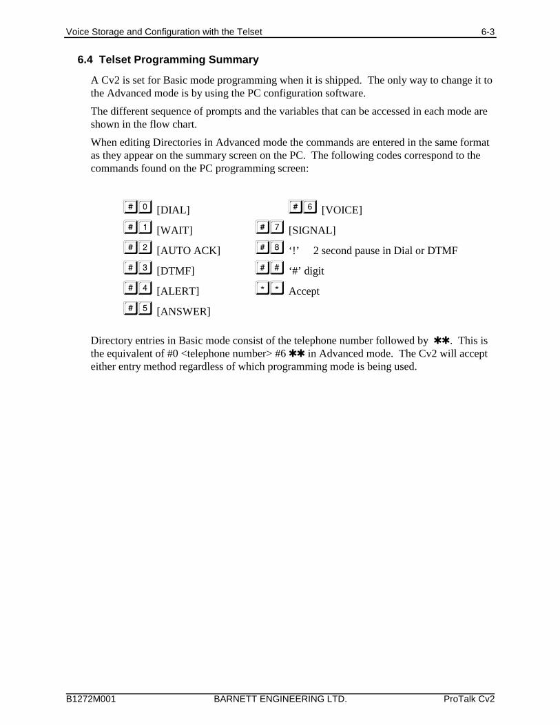
Voice Storage and Configuration with the Telset 6-3
B1272M001 BARNETT ENGINEERING LTD. ProTalk Cv2
6.4 Telset Programming Summary
A Cv2 is set for Basic mode programming when it is shipped. The only way to change it tothe Advanced mode is by using the PC configuration software.
The different sequence of prompts and the variables that can be accessed in each mode areshown in the flow chart.
When editing Directories in Advanced mode the commands are entered in the same formatas they appear on the summary screen on the PC. The following codes correspond to thecommands found on the PC programming screen:
[DIAL] [VOICE]
[WAIT] [SIGNAL]
[AUTO ACK] ‘!’ 2 second pause in Dial or DTMF
[DTMF] ‘#’ digit
[ALERT] Accept
[ANSWER]
Directory entries in Basic mode consist of the telephone number followed by rr. This isthe equivalent of #0 <telephone number> #6 rr in Advanced mode. The Cv2 will accepteither entry method regardless of which programming mode is being used.
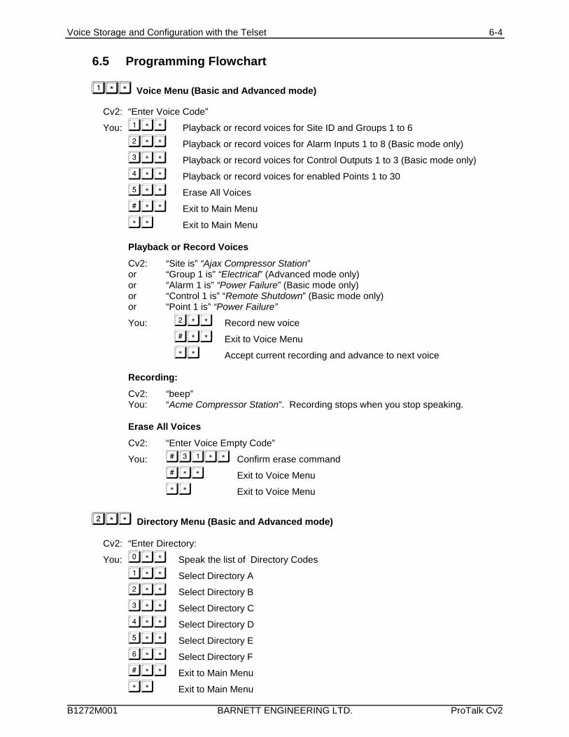
Voice Storage and Configuration with the Telset 6-4
B1272M001 BARNETT ENGINEERING LTD. ProTalk Cv2
6.5 Programming Flowchart
Voice Menu (Basic and Advanced mode)
Cv2: “Enter Voice Code”
You: Playback or record voices for Site ID and Groups 1 to 6
Playback or record voices for Alarm Inputs 1 to 8 (Basic mode only)
Playback or record voices for Control Outputs 1 to 3 (Basic mode only)
Playback or record voices for enabled Points 1 to 30
Erase All Voices
Exit to Main Menu
Exit to Main Menu
Playback or Record Voices
Cv2: “Site is” “Ajax Compressor Station”or “Group 1 is” “Electrical” (Advanced mode only)or “Alarm 1 is” “Power Failure” (Basic mode only)or “Control 1 is” “Remote Shutdown” (Basic mode only)or “Point 1 is” “Power Failure”
You: Record new voice
Exit to Voice Menu
Accept current recording and advance to next voice
Recording:
Cv2: “beep”You: “Acme Compressor Station”. Recording stops when you stop speaking.
Erase All Voices
Cv2: “Enter Voice Empty Code”
You: Confirm erase command
Exit to Voice Menu
Exit to Voice Menu
Directory Menu (Basic and Advanced mode)
Cv2: “Enter Directory:
You: Speak the list of Directory Codes
Select Directory A
Select Directory B
Select Directory C
Select Directory D
Select Directory E
Select Directory F
Exit to Main Menu
Exit to Main Menu
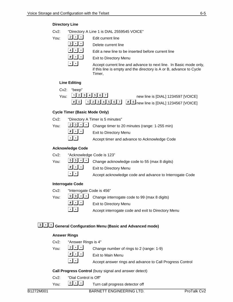
Voice Storage and Configuration with the Telset 6-5
B1272M001 BARNETT ENGINEERING LTD. ProTalk Cv2
Directory Line
Cv2: “Directory A Line 1 is DIAL 2559545 VOICE”
You: Edit current line
Delete current line
Edit a new line to be inserted before current line
Exit to Directory Menu
Accept current line and advance to next line. In Basic mode only,if this line is empty and the directory is A or B, advance to CycleTimer,
Line Editing
Cv2: “beep”
You: new line is [DIAL] 1234597 [VOICE]
new line is [DIAL] 1234567 [VOICE]
Cycle Timer (Basic Mode Only)
Cv2: “Directory A Timer is 5 minutes”
You: Change timer to 20 minutes (range: 1-255 min)
Exit to Directory Menu
Accept timer and advance to Acknowledge Code
Acknowledge Code
Cv2: “Acknowledge Code is 123”
You: Change acknowledge code to 55 (max 8 digits)
Exit to Directory Menu
Accept acknowledge code and advance to Interrogate Code
Interrogate Code
Cv2: “Interrogate Code is 456”
You: Change interrogate code to 99 (max 8 digits)
Exit to Directory Menu
Accept interrogate code and exit to Directory Menu
General Configuration Menu (Basic and Advanced mode)
Answer Rings
Cv2: “Answer Rings is 4"
You: Change number of rings to 2 (range: 1-9)
Exit to Main Menu
Accept answer rings and advance to Call Progress Control
Call Progress Control (busy signal and answer detect)
Cv2: “Dial Control is Off”
You: Turn call progress detector off
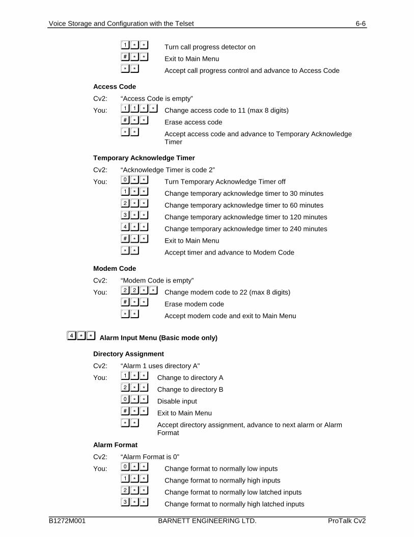
Voice Storage and Configuration with the Telset 6-6
B1272M001 BARNETT ENGINEERING LTD. ProTalk Cv2
Turn call progress detector on
Exit to Main Menu
Accept call progress control and advance to Access Code
Access Code
Cv2: “Access Code is empty”
You: Change access code to 11 (max 8 digits)
Erase access code
Accept access code and advance to Temporary AcknowledgeTimer
Temporary Acknowledge Timer
Cv2: “Acknowledge Timer is code 2”
You: Turn Temporary Acknowledge Timer off
Change temporary acknowledge timer to 30 minutes
Change temporary acknowledge timer to 60 minutes
Change temporary acknowledge timer to 120 minutes
Change temporary acknowledge timer to 240 minutes
Exit to Main Menu
Accept timer and advance to Modem Code
Modem Code
Cv2: “Modem Code is empty”
You: Change modem code to 22 (max 8 digits)
Erase modem code
Accept modem code and exit to Main Menu
Alarm Input Menu (Basic mode only)
Directory Assignment
Cv2: “Alarm 1 uses directory A"
You: Change to directory A
Change to directory B
Disable input
Exit to Main Menu
Accept directory assignment, advance to next alarm or AlarmFormat
Alarm Format
Cv2: “Alarm Format is 0”
You: Change format to normally low inputs
Change format to normally high inputs
Change format to normally low latched inputs
Change format to normally high latched inputs
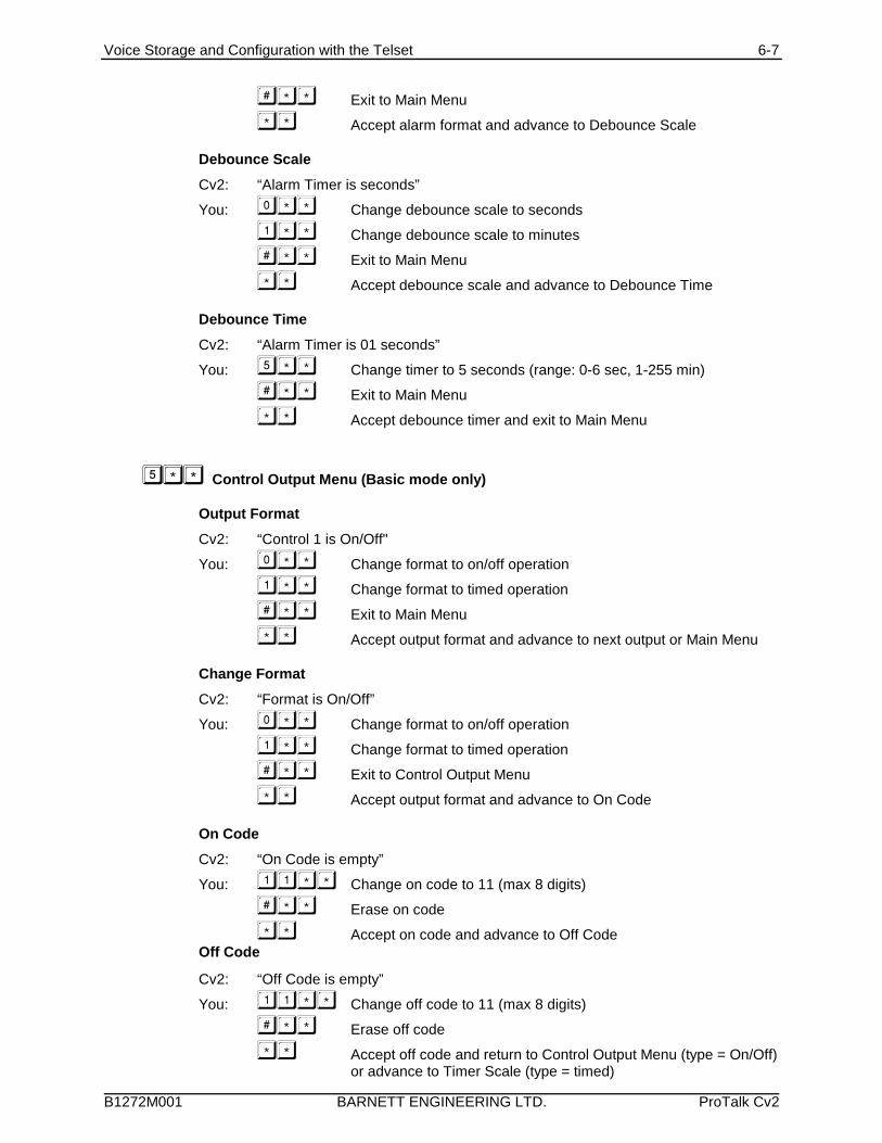
Voice Storage and Configuration with the Telset 6-7
B1272M001 BARNETT ENGINEERING LTD. ProTalk Cv2
Exit to Main Menu
Accept alarm format and advance to Debounce Scale
Debounce Scale
Cv2: “Alarm Timer is seconds”
You: Change debounce scale to seconds
Change debounce scale to minutes
Exit to Main Menu
Accept debounce scale and advance to Debounce Time
Debounce Time
Cv2: “Alarm Timer is 01 seconds”
You: Change timer to 5 seconds (range: 0-6 sec, 1-255 min)
Exit to Main Menu
Accept debounce timer and exit to Main Menu
Control Output Menu (Basic mode only)
Output Format
Cv2: “Control 1 is On/Off"
You: Change format to on/off operation
Change format to timed operation
Exit to Main Menu
Accept output format and advance to next output or Main Menu
Change Format
Cv2: “Format is On/Off”
You: Change format to on/off operation
Change format to timed operation
Exit to Control Output Menu
Accept output format and advance to On Code
On Code
Cv2: “On Code is empty”
You: Change on code to 11 (max 8 digits)
Erase on code
Accept on code and advance to Off CodeOff Code
Cv2: “Off Code is empty”
You: Change off code to 11 (max 8 digits)
Erase off code
Accept off code and return to Control Output Menu (type = On/Off)or advance to Timer Scale (type = timed)
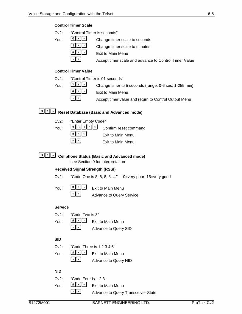
Voice Storage and Configuration with the Telset 6-8
B1272M001 BARNETT ENGINEERING LTD. ProTalk Cv2
Control Timer Scale
Cv2: “Control Timer is seconds”
You: Change timer scale to seconds
Change timer scale to minutes
Exit to Main Menu
Accept timer scale and advance to Control Timer Value
Control Timer Value
Cv2: “Control Timer is 01 seconds”
You: Change timer to 5 seconds (range: 0-6 sec, 1-255 min)
Exit to Main Menu
Accept timer value and return to Control Output Menu
Reset Database (Basic and Advanced mode)
Cv2: “Enter Empty Code"
You: Confirm reset command
Exit to Main Menu
Exit to Main Menu
Cellphone Status (Basic and Advanced mode) see Section 9 for interpretation
Received Signal Strength (RSSI)
Cv2: “Code One is 8, 8, 8, 8, ..." 0=very poor, 15=very good
You: Exit to Main Menu
Advance to Query Service
Service
Cv2: “Code Two is 3”
You: Exit to Main Menu
Advance to Query SID
SID
Cv2: “Code Three is 1 2 3 4 5"
You: Exit to Main Menu
Advance to Query NID
NID
Cv2: “Code Four is 1 2 3"
You: Exit to Main Menu
Advance to Query Transceiver State
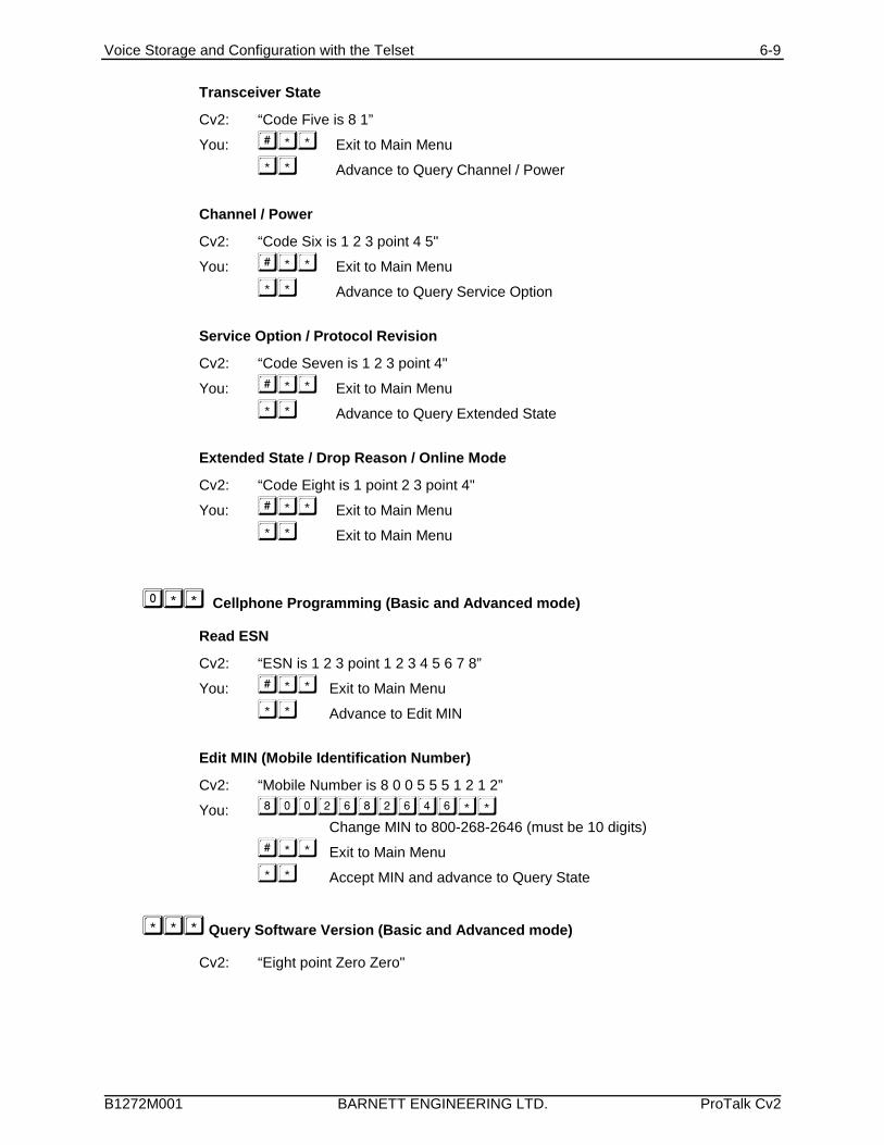
Voice Storage and Configuration with the Telset 6-9
B1272M001 BARNETT ENGINEERING LTD. ProTalk Cv2
Transceiver State
Cv2: “Code Five is 8 1”
You: Exit to Main Menu
Advance to Query Channel / Power
Channel / Power
Cv2: “Code Six is 1 2 3 point 4 5"
You: Exit to Main Menu
Advance to Query Service Option
Service Option / Protocol Revision
Cv2: “Code Seven is 1 2 3 point 4"
You: Exit to Main Menu
Advance to Query Extended State
Extended State / Drop Reason / Online Mode
Cv2: “Code Eight is 1 point 2 3 point 4"
You: Exit to Main Menu
Exit to Main Menu
Cellphone Programming (Basic and Advanced mode)
Read ESN
Cv2: “ESN is 1 2 3 point 1 2 3 4 5 6 7 8”
You: Exit to Main Menu
Advance to Edit MIN
Edit MIN (Mobile Identification Number)
Cv2: “Mobile Number is 8 0 0 5 5 5 1 2 1 2”
You:Change MIN to 800-268-2646 (must be 10 digits)
Exit to Main Menu
Accept MIN and advance to Query State
Query Software Version (Basic and Advanced mode)
Cv2: “Eight point Zero Zero"
Voice Editor 7-1
B1272M001 BARNETT ENGINEERING LTD. ProTalk Cv2
7 Voice Editor
7.1 Voice Editor
Access to the Voice Editor is through the drop-down File menu.
The voice editor is a utility for manipulating and organizing the individual phrases that theCv2 uses to identify groups, points and the site ID. These phrases are packaged into amessage (.msg) file that can be transferred to and from the unit. Adding, changing orremoving phrases can be done either through the programming telephone set or by editing amessage file and transferring it to the unit.
The phrases that make up the message file are displayed in the Site ID, Groups and Points listboxes. A message file may contain any number of phrases up to the maximum of 37 whenevery phrase is programmed for a system with all points and groups active. A message filecan be constructed from an existing one or entirely with new phrases.
If you want to edit an existing message file, use the Load button in the Message section toselect a file. The contents of the message file will be displayed with the designation “in .msgfile” if a phrase is present or with the designation “empty” if there is no phrase for thatlocation. If you have the configuration database that is associated with this message fileloaded in the main program and if the names for each phrase have been programmed in thedatabase, you can turn on the Use Text Names to include the names of the phrases in thedisplay. Do not display the text names if they do not correspond with the associated phrases.
If the pre-recorded message file is not on disk but is present in the Cv2, it can be downloadedby selecting the Read from ProTalk button in the Message section.
Adding individual phrase (.vox) files is done by selecting the location where the phrase will beused and then pressing the Load button in the Phrase section (or double-clicking the location). The file selected in the Open File dialog will be placed at that location.
Press the Clear button to remove a selected phrase.
Individual phrases that were part of a previously recorded message file can be saved to disk bypressing the Save button. A suitable name for the file is required; the program does notattempt to provide a default name even if there is a text name available. External files (.voxfiles taken from a phrase file on the hard drive) that have been loaded cannot be saved in thismanner; use the Windows Explorer to copy these files.
All of the information concerning phrases shown in the editor can be saved to file by pressingthe Save button in the Configuration section. Previously saved configurations can be restoredby pressing the Load button in the Configuration section. Loading a new configurationreplaces all currently displayed data.
Important: The phrase and message data is not embedded in the configuration file, it onlycontains pointers to the input data members. When the program generates a new message fileit locates the source phrase data by using either the file names of the phrases or the loadedmessage file. If these files are relocated after they have been selected in the editor, an errorwill occur when the message file is being generated.
Voice Editor 7-2
B1272M001 BARNETT ENGINEERING LTD. ProTalk Cv2
Controls in the Voice Editor dialog box are:
Individual Voice Phrase Section
Hardware
The setting of the tab control at the bottom of the box determines which part ofthe message configuration is shown in the phrase list boxes.
Use Text Names
This check box controls the display of the text names (Site Name, Point Name andGroup Name) that are in the background programming session. Turning thisfunction on is only of use if the text names match the phrases in the current voiceediting session. Information is these text fields is for reference and is not used bythe Cv2.
Site ID Tab
A single text line displaying the current status of the Site ID phrase.
Depending on what has been loaded into the editor, one of the following willappear in the location for the Site ID phrase.
empty the location contains no phrase data
in .msg file the phrase is contained in a loaded message file
<File path\file name> the phrase is in an individual file has been loadedat this location
Groups Tab
A 6 line list box displaying the current status of the group phrases.
Contents of each line is as described for the Site ID above.
Points Tab
A 30 line list box displaying the current status of the point phrases.
Contents of each line is as described for the Site ID above.
Load
The position in the list where the phrase is to be used must be selected beforepressing this button. A File Open dialog box is used to select the required file. The file type has the extension .vox and must have either been processed by thewave converter or previously extracted from a message file.
Clear
The position in the list where the phrase is to be removed must be selected beforepressing this button.
Save
The location for the phrase that is to be saved must be selected before pressingthis button. A File Save dialog box is used to set the file name and location. Thesaved file is extracted from the currently loaded message file and saved with the.vox extension.
Voice Editor 7-3
B1272M001 BARNETT ENGINEERING LTD. ProTalk Cv2
Message File Section
Load
A File Open dialog box is used to select the required message file with the .msgextension. Message files contain the phrases used by the Cv2 to identify Site ID,Groups and Points. If there are individual phrases with a file location present youwill have the option of writing over them or leaving them in place when the newmessage file is loaded.
Save
A File Save dialog box is used to select the location and name of a message file. The saved file is built from the information in the individual phrase list boxes. Where a file name for an external phrase file is found, that file is opened and thedata merged into the output message file. Where the phrase is contained in thecurrently loaded message file, the phrase data is extracted and merged into theoutput message file. If the save process is unable to open any of the source filesan error will be reported and the process ended.
Read from ProTalk
Before this button is pressed, a Cv2 must be connected to the PC with thecommunications cable. After the message file has been read from the unit a FileSave dialog box opens to allow the location and name to be entered. This filenow becomes the loaded message file as though it was selected by the Loadoperation.
Write to ProTalk
A message file that is currently stored on disk can be transferred to the Cv2. Thefile must be on disk; the information in the current voice editing session is notused directly. If you want to transfer the current session it must be saved to diskfirst.
Com Port
The setting of this combo box determines which serial port is used for thecommunications with the Cv2.
Configuration File Section
Load
A File Open dialog box is used to select a previously saved configuration file withthe .vcf extension.
Save
A File Save dialog box is used to select the location and name of the storedconfiguration file. A configuration file does not contain any phrase data, onlypointers to the source location for the phrases. The file is saved with a .vcfextension.
Voice Editor 7-4
B1272M001 BARNETT ENGINEERING LTD. ProTalk Cv2
7.2 Wave File Conversion
Access to the wave file converter is through the drop-down File menu.
The Cv2 uses Adaptive Differential Pulse Code Modulation (ADPCM) operating at 32 kbps toconvert audio signals to digital form. ADPCM converted voice phrases are specificallydelimited and padded for use by the Cv2. This wave file converter allows you to create phrasefiles using the audio functions available in a PC instead of recording the phrases through theprogramming telephone.
When creating a phrase on the PC, the recorder should be set for either 8 or 16 bit sampling ata rate of 8,000 bytes per second. Higher sample rates do not produce better audio quality butif a faster rate is used it should be a multiple of 8,000. Stereo files cannot be converted.
Press the Source button to select the wave (.wav) file that is to be converted. Press thedestination button to select a name and location for the output ADPCM file. Press Convert togenerate the output file.
The generated ADPCM tile has the extension .vox and can be used by the Voice Editor tocreate message files for the Cv2.
Specifications 8-1
B1272M001 BARNETT ENGINEERING LTD. ProTalk Cv2
8 Specifications
8.1 General
Alarm Inputs • 8 inputs: analog or digital, latching or momentary; plug inscrew terminal block.
• analog: 0 to 5 VDC, 100k input impedance
• digital: normally open or normally closed, ground closureor +10 to +30 VDC input; optionally configured foracknowledge input.
Control Outputs • 8 independent open collector outputs controlled by DTMFcodes; voice announcement when operated; plug in screwterminal block; optionally configured for alarm statusindication. Rated 0.4 A, 50 volts max.
Programming Connection • DB9 - RS232, 9600 baud
Record Connection • RJ11, using standard telephone set
Voice Quality • Digitized, toll quality, 32 kbps ADPCM
Power • +11 to +28 VDC, 125 mA idle, 750mA transmitting; plugin screw terminal block
Environment • -30oC to +50oC
Physical • 8.5"L x 6.0"W x 3.0"D
Cellular Telephone • Internal Kyocera M200 CDMA
Antenna Impedance • 50 ohms
8.2 Programmable Features
Voice Messages • Site identification, Group identification, Alarm inputs, andcontrol outputs; 60 seconds maximum, non-volatile
Alarm Type • Individually configured for digital normally open, digitalnormally closed, or analog 0-5 V
Analog Alarm Range • -999.9 to +999.9
Alarm Groups • Alarms can be assigned to one of 8 groups. All alarms in agroup use the same directory when calling out.
Shifts • Up to 4 shifts can be used. The current setting of the shiftinstructs a group to use one of the six directories.
Interval Timer • Two-stage timer which uses the short interval several timesbefore switching to a long interval. Short and long
Specifications 8-2
B1272M001 BARNETT ENGINEERING LTD. ProTalk Cv2
intervals are adjustable from 1 to 249 minutes; the shorttimer can be used from 1 to 9 times.
Acknowledge Code • Stops the transmission cycle when received. 1 to 7 DTMFdigits with individual codes allowed for each group.
Interrogate Code • Forces annunciation of all active alarms; analog levels,totalizer readings and interval timers. 1 to 7 DTMF digitswith individual codes allowed for each group.
8.3 Telephone
Directory Structure • Up to 20 numbers in each of the 6 directories; eachdirectory can hold up to 200 digits.
Access • Multiple methods of security are available to restrict accessand to control the unit.
8.4 Options
Packaged model • NEMA 4 enclosure
• Battery-backed power supply
• Programming telephone set
Cellphone Status Codes 9-1
B1272M001 BARNETT ENGINEERING LTD. ProTalk Cv2
9 Cellphone Status CodesFollowing is summary of the transceiver codes that can returned to the telset from the cellphoneconfiguration section.
9.1 Received Signal Strength Indicator - RSSI (code 1)Speaks “Code One is 8, 8, 8, 8, ....” where 0 = very poor, 15 = very good
9.2 Service (code 2)Speaks “Code Two is AB”, where
A = Current ServiceOFF = No Service0: Analog Service1: CDMA Cellular Service2: CDMA PCS Service3: Sleep Mode
B = roaming indicator0 = normal1-8 = roaming
9.3 SID (code 3)Speaks the 5 digit System Identification
9.4 NID (code 4)Speaks the 3 digit Network Identification
9.5 State (code 5)
Speaks “Code Five is AB” where AB is the two character transceiver state 00: No Service (either mode)
Analog States:01: Initialization02: Idle03: Voice Channel Initialization04: Waiting For Order05: Waiting For Answer06: Conversation07: Release08: System Access
CDMA States:81: Initialization82: Idle83: Voice Channel Initialization84: Waiting For Order85: Waiting For Answer86: Conversation87: Release88: Update Overhead Information89: Mobile Station Origination Attempt8A: Page Response8B: Order/Message Response8C: Registration Access8D: Message Transmission
Cellphone Status Codes 9-2
B1272M001 BARNETT ENGINEERING LTD. ProTalk Cv2
9.6 Channel / Power (code 6)
Speaks “Code Six is ABC point DE”, whereABC = current transceiver center frequency channelDE = current transmitter power (negative dBm)
9.7 Service Option / Protocol Revision (code 7)
Speaks “Code Seven is ABC, point D”, where: ABC = service option
000: Rejection or Wildcard Voice001: Basic Variable Rate Voice002: Mobile Station Loopback003: Enhanced Variable Rate Voice004: Asynchronous Data (IS-99)006: Short Message (IS-637)007: Internet Standard PPP Packet Data (IS-657)009: Mobile Station Loopback over Rate Set 2012: Asynchronous Data over Rate Set 2014: Short Message using Multiplex Option 2015: Internet Standard PPP Packet Data over Rate Set 2017: High Rate Voice018: Over The Air Provisioning Administration over Rate Set 1019: Over The Air Parameter Administration over Rate Set 2033: 3G Packet Data054: 3G Markov SO055: G Loopback SO104: Asynchronous Data (IS-707)107: Internet Standard PPP Packet Data (IS-707)800: Speech Service Option (13K)801: Speech Service Option (IS-96)802: Markov Service Option803: Data Services Service Option, HACK Packet Method828: Markov Service Option (13k)829: Wide Lock Loop phone off hook830: Markov Service Option (8k)831: Markov Service Option (13k)832: Internet Standard PPP Packet Data Service (QC Proprietary) over Rate Set 2833: Asynchronous Data Service (QC Proprietary) over Rate Set 2
D = Current Protocol Revision in Use0: Unrecognized / non-CDMA 1: IS-95/J-STD-0082: IS-95-A3: IS-95-A + TSB744: TIA/EIA-95-B Phase 15: TIA/EIA-95-B Phase 26: IS-2000 (Release 0)7: IS-2000-A (Release A)
Cellphone Status Codes 9-3
B1272M001 BARNETT ENGINEERING LTD. ProTalk Cv2
9.8 Extended State/ Drop Reason/ Online Mode (code 8)
Speaks “Code Eight is A point BC point D”, where:A = Power Available
0: No Power to Transceiver1: Module Power is On
BC = Call Dropped Reason00: Phone is Offline01: Phone is CDMA locked until Power Cycle02: Phone has No Service03: Call has Ended Abnormally04: Received Intercept from Base Station - Origination only05: Received Reorder from Base Station - Origination only06: Received Release from Base Station - No Reason Given/Normal07: Received Release from Base Station – Service Option Reject08: Received Incoming Call from Base Station09: Received Alert Stop from Base Station - Incoming only10: Client Ended the Call11: Received End Activation - Over-the-Air Service Provisioning Call only12: Mobile Call Aborts the Origination/Conversation13: Call Origination or Call Failed due to NDSS Failure14: Call End due to Maximum Access Probe
D = Online Mode0: Mode Information Not Initialized1: Phone Is in ONLINE Mode2: Phone Is in OFFLINE Mode4: Phone Is Powering Off5: Phone Is Resetting/Power Cycling
Warranty 10-1
B1272M001 BARNETT ENGINEERING LTD. ProTalk Cv2
10 Warranty
Barnett Engineering Ltd. warrants that all equipment supplied shall be free fromdefects in material or workmanship at the time of delivery. Such warranty shallextend from the time of delivery for a period of one year. Buyer must provide writtennotice to Barnett Engineering Ltd. within this prescribed warranty period of anydefect. If the defect is not the result of improper usage, service, maintenance, orinstallation and equipment has not been otherwise damaged or modified afterdelivery, Barnett Engineering Ltd. shall either replace or repair the defective part orparts of equipment or replace the equipment or refund the purchase price at BarnettEngineering Ltd.’s option after return of such equipment by buyer to BarnettEngineering Ltd. Shipment to Barnett Engineering Ltd.’s facility shall be borne onaccount of buyer.
(1) Consequential Damages: Barnett Engineering Ltd. shall not be liable for anyincidental or consequential damages incurred as a result of any defect in anyequipment sold hereunder and Barnett Engineering Ltd.’s liability is specificallylimited to its obligation described herein to repair or replace a defective part orparts covered by this warranty.
(2) Exclusive Warranty: The warranty set forth herein is the only warranty, oral orwritten, made by Barnett Engineering Ltd. and is in lieu of and replaces all otherwarranties, expressed or implied, including the warranty of merchantability andthe warranty of fitness for particular purpose.