Embed Size (px)
Citation preview
WARRANTY
Great Planes® Model Manufacturing Co. box guarantees this kit to be free from defects in both material and workmanship at the date of purchase.This warranty does not cover any component parts damaged by use or modification. In no case shall Great Planes’ liability exceed the original costof the purchased kit. Further, Great Planes reserves the right to change or modify this warranty without notice.
In that Great Planes has no control over the final assembly or material used for final assembly, no liability shall be assumed nor accepted for anydamage resulting from the use by the user of the final user-assembled product. By the act of using the user-assembled product, the user accepts allresulting liability.
If the buyer is not prepared to accept the liability associated with the use of this product, the buyer is advised to return this kit immediatelyin new and unused condition to the place of purchase.
To make a warranty claim send the defective part or item to Hobby Services at the address below:
Hobby Services3002 N. Apollo Dr. Suite 1
Champaign IL 61822USA
Include a letter stating your name, return shipping address, as much contact information as possible (daytime telephone number, fax number, e-mailaddress), a detailed description of the problem and a photocopy of the purchase receipt. Upon receipt of the package the problem will be evaluated asquickly as possible.
READ THROUGH THIS MANUAL BEFORE STARTINGCONSTRUCTION. IT CONTAINS IMPORTANTINSTRUCTIONS AND WARNINGS CONCERNING THEASSEMBLY AND USE OF THIS MODEL.
RV4PP03 V1.0 Entire Contents © Copyright 2004 Printed in USA
Champaign, IL(217) 398-8970, Ext. 5
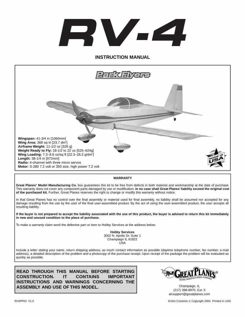
INSTRUCTION MANUAL
Wingspan: 41-3/4 in [1060mm] Wing Area: 368 sq in [23.7 dm2] Airframe Weight: 11-1/2 oz [326 g]Weight Ready to Fly: 18-1/2 to 22 oz [525–624g]Wing Loading: 7.3–8.6 oz/sq ft [22.3–26.2 g/dm2] Length: 38-1/4 in [972mm] Radio: 4-channel with three micro servosMotor: S-280 7.2 volt or 350 size, high power 7.2 volt
INTRODUCTION.................................................................................2SAFETY PRECAUTIONS...................................................................2DECISIONS YOU MUST MAKE .........................................................3
Radio Equipment.........................................................................3Speed Control .............................................................................3Motor System ..............................................................................3Battery Recommendations..........................................................4Performance Options ..................................................................4Chargers......................................................................................5Covering ......................................................................................5Building Board.............................................................................6
ADDITIONAL ITEMS REQUIRED......................................................6Hardware & Accessories.............................................................6Adhesives & Building Supplies....................................................6Optional Supplies & Tools ...........................................................6
IMPORTANT BUILDING NOTES .......................................................6DIE-CUT PATTERNS..........................................................................8METRIC CONVERSIONS...................................................................8BUILDING INSTRUCTIONS...............................................................9BUILD THE TAIL SURFACES ............................................................9BUILD THE WING.............................................................................10
Build the Wing Panels ...............................................................10Join the Wing Panels.................................................................13Build the Ailerons ......................................................................14
BUILD THE FUSELAGE...................................................................16Frame the Sides ........................................................................16Finish the Fuselage...................................................................18Install the Pushrods...................................................................24
COVER THE MODEL .......................................................................26Suggested Covering Sequence ................................................26Add Washout .............................................................................26
FINAL ASSEMBLY...........................................................................27Join the Tail Surfaces ................................................................27Hook Up the Controls................................................................28Mount the Landing Gear ...........................................................28Assemble the Gear Drive ..........................................................29
MOUNT THE CANOPY, COWL & WHEEL PANTS..........................30PREPARE THE MODEL FOR FLYING ............................................32
Balance the Model ....................................................................32Set the Control Throws..............................................................33
PREFLIGHT......................................................................................34Charge the Transmitter Batteries ..............................................34Identify Your Model ....................................................................34Ground Inspection.....................................................................34Range Check.............................................................................34
PERFORMANCE TIPS .....................................................................35Cycle the Batteries ....................................................................35Examine the Propeller...............................................................35Motor Care ................................................................................35Oil the Wheels ...........................................................................35
MOTOR SAFETY PRECAUTIONS ..................................................35AMA SAFETY CODE (excerpts).....................................................35FIND A SAFE PLACE TO FLY .........................................................36FLYING .............................................................................................36
Takeoff .......................................................................................36Flight..........................................................................................36Landing......................................................................................37ROG (Rise off Ground) Takeoff .................................................37
2-VIEW DRAWING ...................................................Back Cover PageFUSELAGE/WING PLAN ...............................Center Pull-Out Section
Congratulations and thank you for purchasing the GreatPlanes RV-4 Park Flyer. The RV-4 Park Flyer is one in aseries of Park Flyers from Great Planes designed to beflown in small areas. Park Flyers are a relatively new classof small, lightweight, slow-flying, fast-building models. SincePark Flyers are small and fly slowly, little space is required.A nearby park, schoolyard or vacant lot becomes animpromptu flying site (see “Find a Safe Place to Fly” onpage 36). Additionally, Park Flyers are perfect for thoseevenings at the field when everybody else is packing uptheir gear, the wind has died, and there is still enough lightto fly a small, slow model that can be kept close-in.
The RV-4 Park Flyer is a slow flying, low-wing model that isrelatively simple to build. It is a sport scale model of the fullsize RV-4. However, if you have never flown an R/C modelbefore, learning to fly the RV-4 Park Flyer all by yourself isnot recommended. As with any airplane, you should find anexperienced modeler to help you with your first flights.Information about R/C clubs and instructors is providedlater in this manual.
For the latest technical updates or manual corrections to theRV-4 Park Flyer, visit the Great Planes web site atwww.greatplanes.com. Open the “Airplanes” link, thenselect the RV-4 Park Flyer kit. If there is new technicalinformation or changes to this model a “tech notice” box willappear in the upper left corner of the page.
1. Even though the Great Planes RV-4 Park Flyer is small,lightweight and flies slowly, if it is not assembled andoperated correctly it could possibly cause injury to yourselfor spectators and damage to property.
2. You must assemble the model according to theinstructions. Do not alter or modify the model, as doing somay result in an unsafe or unflyable model. In a few casesthe instructions may differ slightly from the photos. In thoseinstances the written instructions should be consideredas correct.
3. You must take time to build straight, true and strong.
4. You must use an R/C radio system that is in first-classcondition. This Park Flyer requires micro servos, a microreceiver and a micro speed control able to handle 5 amps.
5. You must correctly install all R/C and other componentsso that the model operates correctly on the ground and inthe air.
PROTECT YOUR MODEL, YOURSELF& OTHERS...FOLLOW THESE
IMPORTANT SAFETY PRECAUTIONS
INTRODUCTIONTABLE OF CONTENTS
2
6. You must check the operation of the model before everyflight to insure that all equipment is operating and that themodel has remained structurally sound. Be sure to checkconnectors often and replace them if they show any signsof wear or fatigue.
7. If you are not already an experienced R/C pilot, youshould fly the model only with the help of a competent,experienced R/C pilot.
Remember: Take your time and follow directions to endup with a well-built model that is straight and true.
Before starting to build, compare the parts in this kit with theParts List, and note any missing parts. Also inspect all partsto make sure they are of acceptable quality. If any parts aremissing, broken or defective, or if you have any questionsabout building or flying this airplane, please contact GreatPlanes at the address or telephone number below. Ifrequesting replacement parts, please provide the full kitname, RV-4 Park Flyer, and the part numbers as listed inthe Parts List.
Great Planes Product Support:3002 N Apollo Drive Suite 1
Champaign, IL 61822Telephone: (217) 398-8970
Fax: (217) 398-7721E-mail: [email protected]
If you’re an inexperienced modeler, we recommend thatyou get assistance from an experienced,knowledgeable modeler to help you with assembly andyour first flights. If you’re not a member of a club, yourlocal hobby shop has information about clubs in your areawhose membership includes experienced pilots.
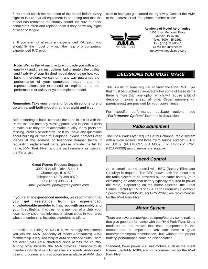
In addition to joining an R/C club, we strongly recommendyou join the AMA (Academy of Model Aeronautics). AMAmembership is required to fly at AMA sanctioned clubs.Thereare over 2,500 AMA chartered clubs across the country.Among other benefits, the AMA provides insurance to itsmembers who fly at sanctioned sites and events. Additionally,training programs and instructors are available at AMA club
sites to help you get started the right way. Contact the AMAat the address or toll-free phone number below:
This is a list of items required to finish the RV-4 Park Flyerthat must be purchased separately. For some of these itemsthere is more than one option which will require a bit ofdecision making ahead of time. Order numbers (inparentheses) are provided for your convenience.
For specific performance package options, see“Performance Options” later in this discussion.
The RV-4 Park Flyer requires a four-channel radio systemwith a micro receiver and three micro servos. Futaba® S3103or S3107 (FUTM0037, FUTM0025) or Hobbico® CS-5(HCAM0090) micro servos are suitable.
An electronic speed control with BEC (Battery EliminatorCircuitry) is required. The BEC allows both the motor andthe radio system to be powered by the same battery (thuseliminating an additional battery typically required to powerthe radio). Depending on the motor selected, the GreatPlanes ElectriFly™ C-10 or C-20 High Frequency ElectronicSpeed Control (GPMM2010 or GPMM2020) are recommendedfor the RV-4 Park Flyer.
There are several motor/gearbox/prop/battery combinationsthat give good performance with the RV-4 Park Flyer. Manymodelers do not realize that each component in thiscombination is important. You can have a goodmotor/gearbox/prop combination, but without the properbattery, performance could be disappointing.
Standard, lower power 280 size motors, such as the GreatPlanes ElectriFly T-280, are not recommended for the RV-4Park Flyer.
Motor System
Speed Control
Radio Equipment
DECISIONS YOU MUST MAKE
Academy of Model Aeronautics5151 East Memorial Drive
Muncie, IN 47302Tele: (800) 435-9262Fax (765) 741-0057
Or via the Internet at:http://www.modelaircraft.org
Note: We, as the kit manufacturer, provide you with a topquality kit and great instructions, but ultimately the qualityand flyability of your finished model depends on how youbuild it; therefore, we cannot in any way guarantee theperformance of your completed model, and norepresentations are expressed or implied as to theperformance or safety of your completed model.
3
The RV-4 Park Flyer also flies well with the Great PlanesElectriFly T-400 Ferrite Motor (GPMG0325). This motorshould be used with the Great Planes ElectriFly T-400 4.1:1Gearbox (GPMG0226). The best prop is the APC 10 x 4.7SloFlyer (APCQ5015). You will also need a 3mm propadapter (GPMQ4600).This combination gives less spirited,but adequate performance, with much cooler motortemperatures and longer motor lifespan.
The RV-4 Park Flyer flies in a very spirited manner with theGreat Planes ElectriFly S-280 Ferrite Motor (GPMG0305),Great Planes ElectriFly S-280 5.0:1 Gearbox (GPMG0200)and APC 10 x 4.7 SloFlyer Prop (APCQ5015). For thiscombination you will also need a 3mm prop adapter(GPMQ4600). With this motor you can also use the GreatPlanes ElectriFly S-280 4.5:1 Gearbox (GPMG0201) or theS-280 4.1:1 Gearbox (GPMG0202). An APC 9 x 6 SloFlyerProp (APCQ5013) would be a better prop with thesegearboxes. The Great Planes ElectriFly 8-cell 1050 mAhNiMH Battery (GPMP0251) is not recommended with thismotor as the added run time could cause the motor tooverheat. This is a high power motor and adequate coolingis important. Be sure to follow the cooling instructions onpage 31, steps 11 & 12 of this manual. Allow 10 – 15 minutesof cooling time between flights.
An even more powerful motor for the RV-4 Park Flyer is theGreat Planes ElectriFly S-370 Ferrite Motor (GPMG0310).This motor is nearly the same physical size as a 280-sizemotor and can be used with the same componentsrecommended above for the S-280 motor. A 20-amp ESCshould be used with this motor and adequate cooling iscritical. It is best to limit this motor to a 7-cell 650 mAhbattery. With an 8-cell 1050 mAh battery, motortemperatures can easily reach 240 degrees, which wouldgreatly reduce the lifespan of the motor. Be sure to followthe cooling instructions on page 31, steps 11 & 12 of thismanual. Allow 20 minutes of cooling time between flights.
The RV-4 Park Flyer can be powered with brushless motorsas well. While these motors and their controllers areexpensive, they give outstanding performance with longerflight times and cooler motor temperatures than the aboveferrite motors.
There are three kinds of battery packs used for electric R/Cmodels: nickel-metal hydride (NiMH), nickel-cadmium(NiCd, pronounced ny-cad) and Lithium Polymer (Li-Po).NiMH and Li-Po batteries are recommended for the RV-4Park Flyer because they provide from two to six times thecapacity of a NiCd battery of the same size and weight.However, it should be noted that NiMH and Li-Po cannot becharged as fast as NiCds. Li-Po batteries also require aspecial charger.
For NiMH and NiCd batteries, each individual cell thatmakes up a battery is 1.2 volts. For a Li-Po battery each cell
is 3.7 volts. Batteries are also rated by their capacity in mAh(milli-Amp-hours), or how much energy they store. A 650mAh battery can supply 1 Ampere for .65 hours (about 39minutes). At a typical average park flyer power requirementof 5 Amps, a 650 mAh battery will last about 7-1/2 minutes.
These are the battery packs recommended for the RV-4Park Flyer:
GPMP0071 – 7-cell, 650 mAh NiMH packGPMP0072 –8-cell, 650 mAh NiMH packGPMP0250 –7-cell, 1050 mAh NiMH packGPMP0251 – 8-cell, 1050 mAh NiMH pack (for 400size motor only)KKMP9100 – Kokam 2-cell, 340 mAh Li-Po packKKMP7100 – Kokam 2-cell, 1500 mAh Li-Po packKKMP8100 – Kokam 3-cell, 1500 mAh Li-Po pack (for400 size motor only)
Caution: Use extreme caution when using Li-Po batterieswith the S-280 and S-370 motors. Due to the very long runtimes these batteries can provide, overheating of thesemotors will occur, resulting in VERY short motor life-spans.
The following performance packages are recommended forthe RV-4 Park Flyer. You may wish to experiment with othercombinations to obtain the performance level you findmost enjoyable.
Performance Options
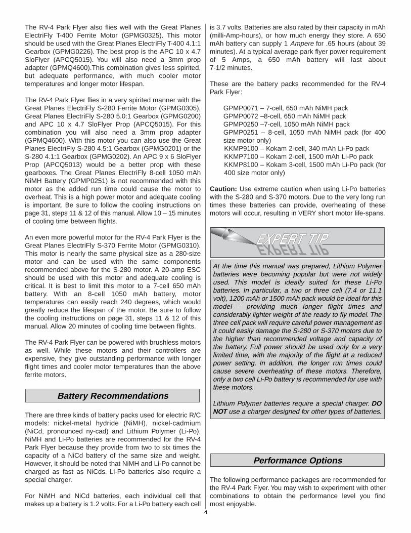
At the time this manual was prepared, Lithium Polymerbatteries were becoming popular but were not widelyused. This model is ideally suited for these Li-Pobatteries. In particular, a two or three cell (7.4 or 11.1volt), 1200 mAh or 1500 mAh pack would be ideal for thismodel – providing much longer flight times andconsiderably lighter weight of the ready to fly model. Thethree cell pack will require careful power management asit could easily damage the S-280 or S-370 motors due tothe higher than recommended voltage and capacity ofthe battery. Full power should be used only for a verylimited time, with the majority of the flight at a reducedpower setting. In addition, the longer run times couldcause severe overheating of these motors. Therefore,only a two cell Li-Po battery is recommended for use withthese motors.
Lithium Polymer batteries require a special charger. DONOT use a charger designed for other types of batteries.
Battery Recommendations
4

Option 1, Good Performance• T-400 Ferrite Motor (GPMG0325)• T-400 4.1:1 Gearbox (GPMG0226)• 10 x 4.7 SloFlyer Prop (APCQ5015)• C-10 ESC (GPMM2010)• 8-cell, 1050 mAh Battery (GPMP0251)• 3mm Prop Adapter (GPMQ4600)
Option 2, Spirited Performance• S-280 Ferrite Motor (GPMG0305)• S-280 5.0:1 Gearbox (GPMG0200)• 10 x 4.7 SloFlyer Prop (APCQ5015)• C-10 ESC (GPMM2010)• 8-cell, 650 mAh Battery (GPMP0072)• 3mm Prop Adapter (GPMQ4600)
Option 3, Ballistic Performance• S-370 Ferrite Motor (GPMG0310)• S-280 5.0:1 Gearbox (GPMG0200)• 9 x 6 SloFlyer Prop (APCQ5013)• C-20 ESC (GPMM2020)• 7-cell, 650 mAh Battery (GPMP0071)• 3mm Prop Adapter (GPMQ4600)
If you are using Li-Po batteries it is critical that you use abattery charger designed specifically for this type of battery.Other types of chargers will not work properly and couldcause the battery to be overcharged, causing it to swell,overheat and rupture – possibly causing a fire if the batteryis being charged near combustible material. If the batterybecomes even warm, disconnect it immediately. NEVERcharge a Li-Po pack unattended. The Great Planes Triton™
charger (GPMM3150) is a suitable charger for Li-Pobatteries. Warning: Even with the proper charger, therisk of a fire is much higher with Li-Po batteries, soalways charge these batteries away from combustiblematerials and carefully monitor the charge process.
Proper charging of Lithium batteries is very important.Consult your charger for charge procedures and forprecautions to observe. At a minimum these should include:1. If the battery becomes damaged, as in a model crash,
immediately remove the battery and place it in a remotearea away from combustible materials. Monitor thebattery for at least 20 minutes. If the battery remainscool, it is safe to transport. If the battery is physicallydamaged, it should be disposed of.
2. If a soft sided battery, such as a Li-Po, is dented evenslightly it should be treated as a damaged battery andimmediately isolated as above.
3. Wear safety glasses when handling damaged batteries.4. When charging lithium batteries, use a Protective
Charge Module that monitors individual cell voltage.5. Whenever you charge a Lithium battery, ensure that the
charger is set to the correct number of cells. Doublecheck the setting, then triple check it!
6. Do not charge a Lithium battery while it is installedinside a model.
7. Charge batteries in a well ventilated area.8. Charge batteries away from combustible materials.9. Charge batteries in an area with smoke and fire detectors.10. Do not charge a Lithium battery at a rate higher than 1C.11. Use a charger specifically designed for the type of
battery being charged.12. Do not charge any battery inside a vehicle.13. Do not wear jewelry or watches when working
with batteries.14. Do not put batteries in your pocket.15. Never charge batteries unattended.
The best type of charger for NiMH and NiCd batteries is apeak charger, because it charges the batteries until they arefully charged, then automatically switches to a tricklecharge mode. The Great Planes ElectriFly Peak Charger(GPMM3000) is suitable for NiMH and NiCd batteries aswell as transmitter battery packs. The Great Planes Tritoncharger (GPMM3150) is also suitable.
The following applies to NiMH and NiCd batteries only:If you have another type of charger that is not a peakcharger, you will have to calculate the length of time it takesto charge the batteries yourself, then turn the charger offwhen the batteries are fully charged. Overcharging thebatteries may damage them. Before you can calculate thetime it takes to charge a battery pack, you first have to knowthe charge rate you are going to use. Nickel-metal hydridesshould be charged at a rate of no more than 1/10 of theircapacity. For the 650 mAh batteries recommended for theRV-4 Park Flyer, this would be a charge rate ofapproximately 65 mAh. Divide the capacity of the batterypack by the charge rate to calculate the charge time. Adischarged 650 mAh battery pack charged at 65 mAh willtake 10 hours to charge.
Charge rate/time recommendations for a fullydischarged pack:• Charge a 650 mAh battery pack at 65 mAh for 10 hours.• Charge a 1050 mAh battery pack at 100 mAh for 11 hours.
IMPORTANT: Monitor the temperature of the batteryfrequently. If the battery becomes warm, disconnect it fromthe charger.
Note: The period required to charge the batteries in theexamples above is for discharged batteries. If the batteryyou are going to charge is not discharged (and you are notusing a peak charger), connect it to the motor on yourmodel. Run the motor until the propeller is turning slowly,thus discharging the battery.
There are several types of covering that may be used on theRV-4 Park Flyer, and a few that are not recommended. Usea covering suitable for lightweight models. Top Flite®
Covering
Chargers
5
EconoKote® and Coverite® CoverLite™ are suitable for theRV-4 Park Flyer.
EconoKote is similar to MonoKote® (used on most regular-size sport models), except EconoKote is lighter and doesnot shrink as tightly, thus making it suitable for lightweightstructures such as that of the RV-4 Park Flyer. EconoKotealso has an adhesive on the back which is activated by theheat of a model airplane covering iron.
Coverite CoverLite is another covering suitable for lightweightstructures (and is the covering that is on the model featuredon the box label). CoverLite has fibers embedded in the filmand is exceptionally strong, yet remains lightweight. It has noadhesive on the back, therefore, you must apply an adhesiveto the structure before application. Use Coverite Balsarite™
Fabric formula (COVR2500) for CoverLite. Do not useBalsarite “film formula.”
Transparent MonoKote film is also suitable for covering theRV-4 Park Flyer, because it is lighter and does not shrink astightly as opaque MonoKote film.
Opaque MonoKote film is not recommended for the RV-4Park Flyer because it is too heavy and shrinks too tightly forthe structure to withstand.
Other lightweight covering materials for park flyer modelsare being developed. Check with your hobby dealer for thelatest products.
You will need a flat board to lay over your workbench that youcan stick pins into.The back of a 2' x 4' ceiling tile or a sectioncut from a sheet of Celotex® insulation board is ideal.
In addition to the items listed in the “Decisions You MustMake” section, following is the list of hardware andaccessories required to finish your RV-4 Park Flyer. Ordernumbers are provided in parentheses.
❏ (1) 1-3/4" Spinner, Red (GPMQ4507)❏ Cellophane tape (for hinges)❏ Double-sided foam tape (for mounting servos)
(GPMQ4440)
The following is a “short list” of the most important buildingsupplies required to build the RV-4 Park Flyer. Werecommend Great Planes Pro™ CA and Epoxy glue.
❏ 1 oz. Thin Pro CA (GPMR6002)❏ 1 oz. Medium Pro CA+ (GPMR6008)❏ CA glue tips (GPMR6033)❏ Hobby knife (HCAR0105)❏ #11 Blades (HCAR0211)❏ Single-edge razor blades (HCAR0212)❏ Small T-pins (HCAR5100)❏ Builder’s triangle (HCAR0480)❏ Electric drill and #68 (1/32"), 1/16" [1.6mm], 1/8"
[3.2mm] and 3/16" [4.8mm] drill bits❏ Small Phillips and flat blade screwdrivers❏ Pliers with wire cutter (HCAR0630)❏ Great Planes Plan Protector™ (GPMR6167) or wax paper❏ HobbyLite™ balsa-colored balsa filler (HCAR3401)❏ Sanding tools and sandpaper assortment❏ Sealing iron (TOPR2100)❏ Razor saw
Here is a list of optional tools that will help you build theRV-4 Park Flyer.
❏ Great Planes CG Machine™ (GPMR2400)❏ Top Flite Precision Magnetic Prop Balancer™ (TOPQ5700)❏ Top Flite Hot Sock™ iron cover (TOPR2175)❏ Straightedge with scale (HCAR0475)❏ Cutting mat (HCAR0456)❏ Masking tape (TOPR8018)❏ CA Debonder (GPMR6039)❏ Great Planes 5-1/2" [140mm] Bar Sander™ (GPMR6169)
and 150-grit adhesive back sandpaper (GPMR6183)❏ Top Flite 320-grit sandpaper (TOPR8030) and 400-grit
sandpaper (TOPR8032)
For the best performance, the RV-4 Park Flyer must be builtlight. The model is designed for a light yet strong structure.Because the finished model is so light, it does not requirethe stronger structures you may be used to in other models.It is not recommended that you strengthen the model asdoing so will add excess weight.
IMPORTANT BUILDING NOTES
Optional Supplies & Tools
Adhesives & Building Supplies
Hardware & Accessories
ADDITIONAL ITEMS REQUIRED
Building Board
6
One of the best ways to insure light weight is to build neatlyand make good-fitting glue joints that require less glue.Here are some tips to help you build neatly and light.
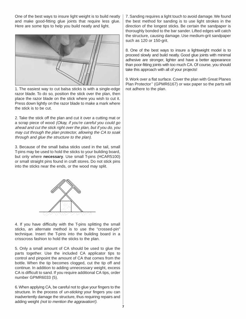
1. The easiest way to cut balsa sticks is with a single-edgerazor blade. To do so, position the stick over the plan, thenplace the razor blade on the stick where you wish to cut it.Press down lightly on the razor blade to make a mark wherethe stick is to be cut.
2. Take the stick off the plan and cut it over a cutting mat ora scrap piece of wood (Okay, if you’re careful you could goahead and cut the stick right over the plan, but if you do, youmay cut through the plan protector, allowing the CA to soakthrough and glue the structure to the plan).
3. Because of the small balsa sticks used in the tail, smallT-pins may be used to hold the sticks to your building board,but only where necessary. Use small T-pins (HCAR5100)or small straight pins found in craft stores. Do not stick pinsinto the sticks near the ends, or the wood may split.
4. If you have difficulty with the T-pins splitting the smallsticks, an alternate method is to use the “crossed-pin”technique. Insert the T-pins into the building board in acrisscross fashion to hold the sticks to the plan.
5. Only a small amount of CA should be used to glue theparts together. Use the included CA applicator tips tocontrol and pinpoint the amount of CA that comes from thebottle. When the tip becomes clogged, cut the tip off andcontinue. In addition to adding unnecessary weight, excessCA is difficult to sand. If you require additional CA tips, ordernumber GPMR6033 (5).
6.When applying CA, be careful not to glue your fingers to thestructure. In the process of un-sticking your fingers you caninadvertently damage the structure, thus requiring repairs andadding weight (not to mention the aggravation!).
7. Sanding requires a light touch to avoid damage.We foundthe best method for sanding is to use light strokes in thedirection of the longest sticks. Be certain the sandpaper isthoroughly bonded to the bar sander. Lifted edges will catchthe structure, causing damage. Use medium-grit sandpapersuch as 120 or 150-grit.
8. One of the best ways to insure a lightweight model is toproceed slowly and build neatly. Good glue joints with minimaladhesive are stronger, lighter and have a better appearancethan poor-fitting joints with too much CA. Of course, you shouldtake this approach with all of your projects!
9.Work over a flat surface. Cover the plan with Great PlanesPlan Protector™ (GPMR6167) or wax paper so the parts willnot adhere to the plan.
7
8
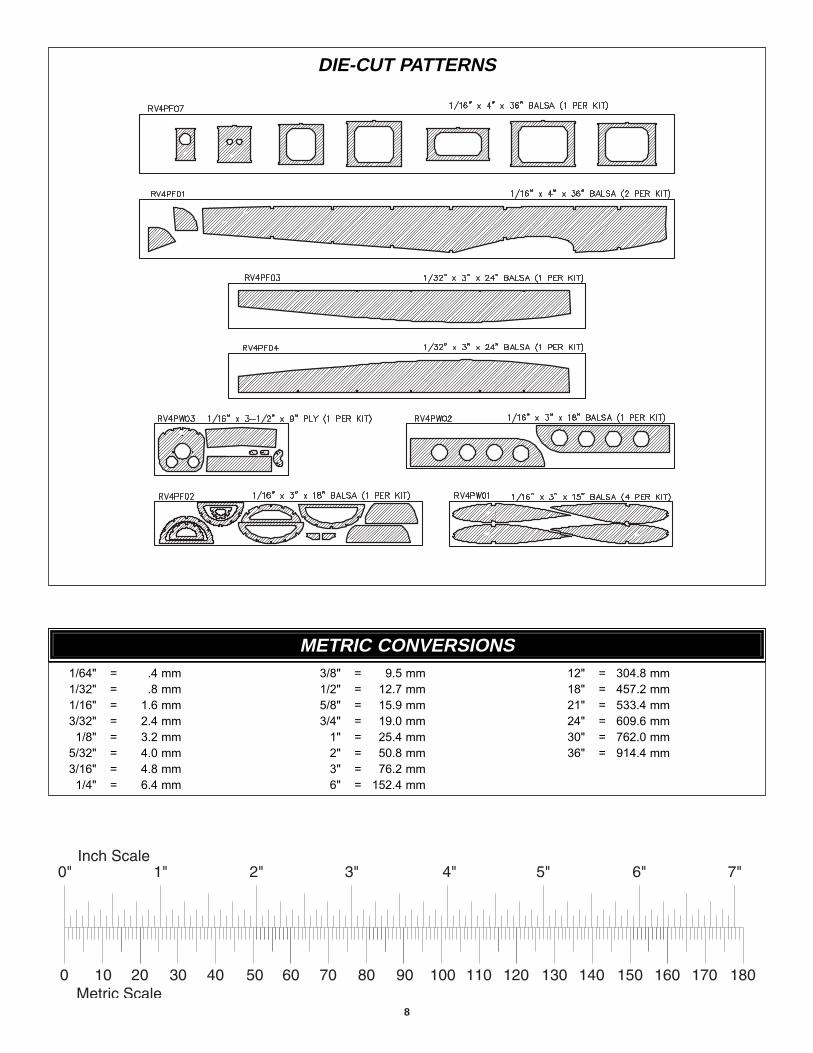
DIE-CUT PATTERNS
1/64" = .4 mm1/32" = .8 mm1/16" = 1.6 mm3/32" = 2.4 mm
1/8" = 3.2 mm5/32" = 4.0 mm3/16" = 4.8 mm
1/4" = 6.4 mm
3/8" = 9.5 mm1/2" = 12.7 mm5/8" = 15.9 mm3/4" = 19.0 mm
1" = 25.4 mm2" = 50.8 mm3" = 76.2 mm6" = 152.4 mm
12" = 304.8 mm18" = 457.2 mm21" = 533.4 mm24" = 609.6 mm30" = 762.0 mm36" = 914.4 mm
METRIC CONVERSIONS
❏ 1. Unroll the plan sheets. Re-roll them inside-out so theywill lie flat. Place the fin/rudder portion of the fuse plan overyour flat building board, then cover it with Great Planes PlanProtector or wax paper so glue will not adhere to the plan.
Note: The bottom of the fin is difficult to see on the fuselageplan. A separate drawing of the fin is located on the wingplan and may be more useful for building the fin.
❏ 2. Find the four hardest 1/8" x 1/4" x 24" [3.2 x 6.4 x 610mm]balsa sticks and set them aside for use as the wing spars.
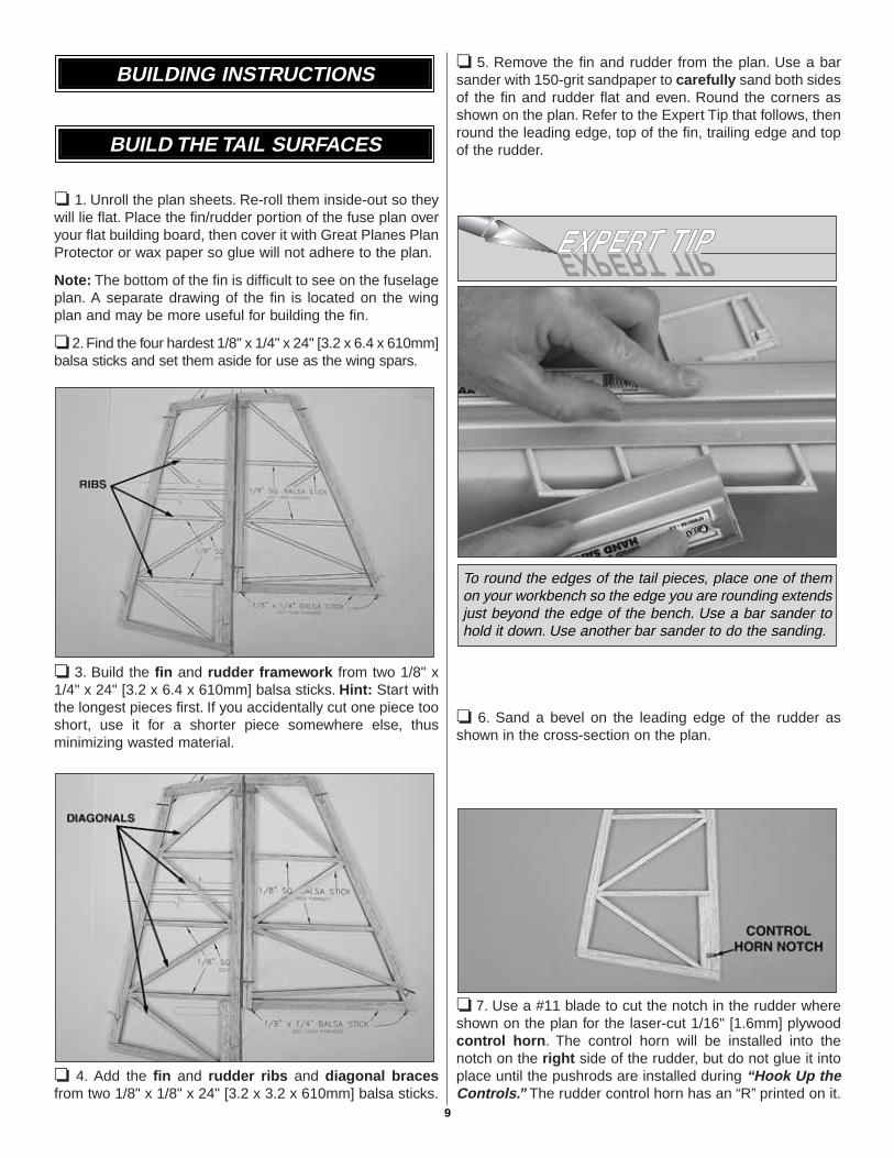
❏ 3. Build the fin and rudder framework from two 1/8" x1/4" x 24" [3.2 x 6.4 x 610mm] balsa sticks. Hint: Start withthe longest pieces first. If you accidentally cut one piece tooshort, use it for a shorter piece somewhere else, thusminimizing wasted material.
❏ 4. Add the fin and rudder ribs and diagonal bracesfrom two 1/8" x 1/8" x 24" [3.2 x 3.2 x 610mm] balsa sticks.
❏ 5. Remove the fin and rudder from the plan. Use a barsander with 150-grit sandpaper to carefully sand both sidesof the fin and rudder flat and even. Round the corners asshown on the plan. Refer to the Expert Tip that follows, thenround the leading edge, top of the fin, trailing edge and topof the rudder.
❏ 6. Sand a bevel on the leading edge of the rudder asshown in the cross-section on the plan.
❏ 7. Use a #11 blade to cut the notch in the rudder whereshown on the plan for the laser-cut 1/16" [1.6mm] plywoodcontrol horn. The control horn will be installed into thenotch on the right side of the rudder, but do not glue it intoplace until the pushrods are installed during “Hook Up theControls.” The rudder control horn has an “R” printed on it.
To round the edges of the tail pieces, place one of themon your workbench so the edge you are rounding extendsjust beyond the edge of the bench. Use a bar sander tohold it down. Use another bar sander to do the sanding.
BUILD THE TAIL SURFACES
BUILDING INSTRUCTIONS
9
❏ 8. Build the stab and elevators from five 1/8" x 1/4" x 24"[3.2 x 6.4 x 610mm] and two 1/8" x 1/8" x 24" [3.2 x 3.2 x610mm] balsa sticks. Be sure to notch the leading edge ofboth elevators where the basswood joiner stick goes. Do notjoin the elevators with the 1/8" x 1/8" x 3" [3.2 x 3.2 x 76mm]basswood stick until instructed to do so.
❏ 9. The same as you did the fin and rudder, remove thestab and elevators from the plans, sand the stab andelevators flat and even, then round the corners whereshown on the plan. Round the tips of the stab and elevators.Round the leading edge of the stab and the trailing edge ofthe elevators. Bevel the leading edge of both elevators asshown in the cross-section on the plan.
❏ 10. Use a #11 blade to cut the notch in the left elevatorwhere shown on the plan for the laser-cut 1/16" [1.6mm]plywood control horn. The control horn will be installed intothe notch on the bottom of the left elevator, but do not glueit into place until the pushrods are installed during “HookUp the Controls.”
❏ 11. Use a bar sander with 150-grit sandpaper to bevel the1/8" x 1/8" x 3" [3.2 x 3.2 x 76mm] basswood elevatorjoiner to match the leading edge of the elevators.
❏ 12. Pin both elevators to the plan upside-down. Check thefit of the elevator joiner and trim if necessary. Use medium CAto securely glue the elevator joiner to the left elevator only.
Start by building the left wing panel first so your progressmatches the photos.
❏ ❏ 1. Cover the left wing panel plan with Great PlanesPlan Protector or wax paper.
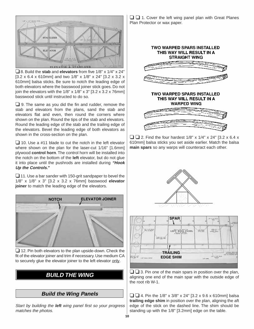
❏ ❏ 2. Find the four hardest 1/8" x 1/4" x 24" [3.2 x 6.4 x610mm] balsa sticks you set aside earlier. Match the balsamain spars so any warps will counteract each other.
❏ ❏ 3. Pin one of the main spars in position over the plan,aligning one end of the main spar with the outside edge ofthe root rib W-1.
❏ ❏ 4. Pin the 1/8" x 3/8" x 24" [3.2 x 9.6 x 610mm] balsatrailing edge shim in position over the plan, aligning the aftedge of the stick on the dashed line. The shim should bestanding up with the 1/8" [3.2mm] edge on the table.
Build the Wing Panels
BUILD THE WING
10
❏ ❏ 5. Starting at the wing tip, glue six laser-cut 1/16"[1.6mm] balsa W2 ribs over the main spar, perpendicular tothe building board. Important: Pin the rear of the ribs firmlyto the TE shim.
❏ ❏ 6. Temporarily place a sheet of 1/32" [0.8mm] balsasheeting on the plan 1/4" [6.4mm] aft of the spar as shownin the above photo. This will space the W1 ribs properly onthe spar. Glue a laser-cut 1/16" [1.6mm] balsa W1 rib inplace over the main spar as shown in the photo.
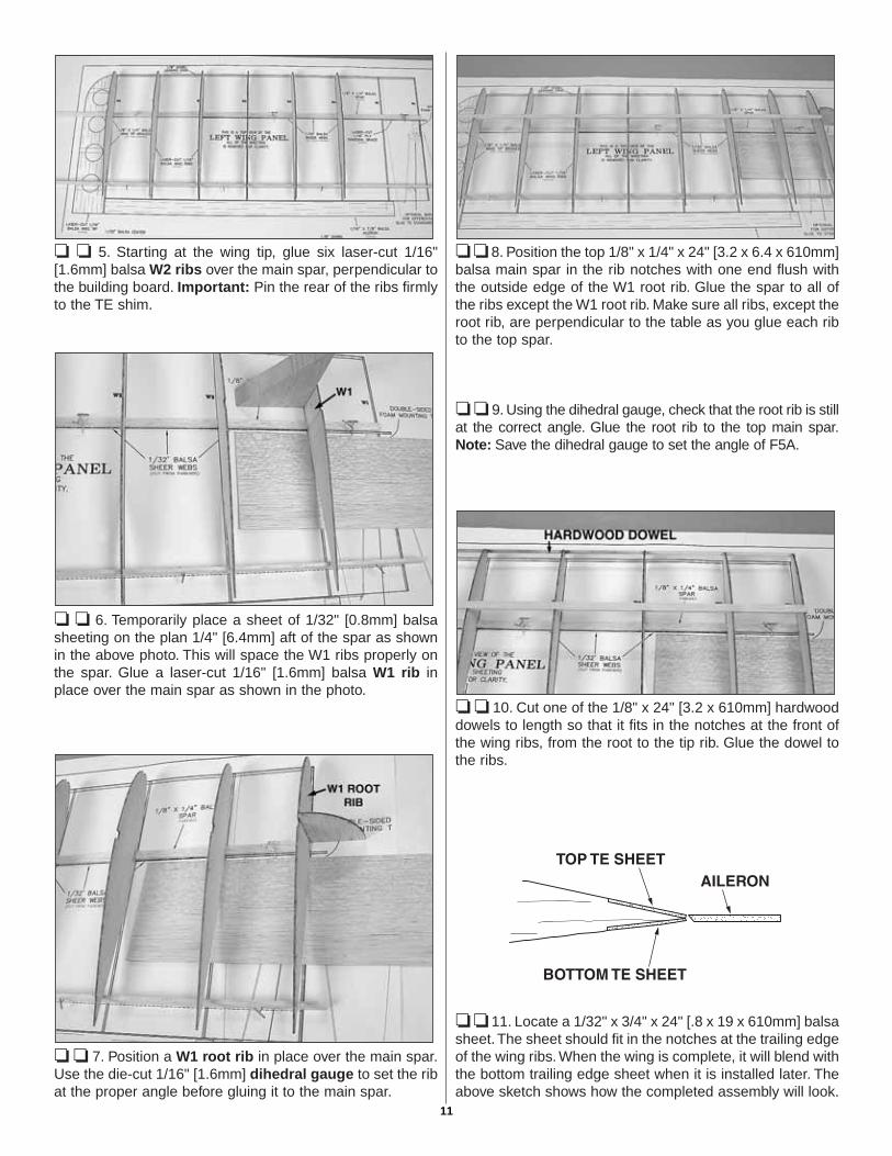
❏ ❏ 7. Position a W1 root rib in place over the main spar.Use the die-cut 1/16" [1.6mm] dihedral gauge to set the ribat the proper angle before gluing it to the main spar.
❏ ❏ 8. Position the top 1/8" x 1/4" x 24" [3.2 x 6.4 x 610mm]balsa main spar in the rib notches with one end flush withthe outside edge of the W1 root rib. Glue the spar to all ofthe ribs except the W1 root rib. Make sure all ribs, except theroot rib, are perpendicular to the table as you glue each ribto the top spar.
❏ ❏ 9. Using the dihedral gauge, check that the root rib is stillat the correct angle. Glue the root rib to the top main spar.Note: Save the dihedral gauge to set the angle of F5A.
❏ ❏ 10. Cut one of the 1/8" x 24" [3.2 x 610mm] hardwooddowels to length so that it fits in the notches at the front ofthe wing ribs, from the root to the tip rib. Glue the dowel tothe ribs.
❏ ❏ 11. Locate a 1/32" x 3/4" x 24" [.8 x 19 x 610mm] balsasheet. The sheet should fit in the notches at the trailing edgeof the wing ribs. When the wing is complete, it will blend withthe bottom trailing edge sheet when it is installed later. Theabove sketch shows how the completed assembly will look.
11
❏ ❏ 12. Glue the top trailing edge sheet to the top of thewing ribs.
❏ ❏ 13. From a 1/32" x 3" x 15" [0.8 x 76 x 380mm] balsasheet, cut and glue shear webs, with the grain runningvertically, to the top and bottom spars in the locations shownon the plan. It is not necessary for the shear webs to beglued to the ribs at this time, but make sure they are gluedsecurely to the wing spars. Do not install shear webs inthe rib bay between the W1 ribs.
❏ ❏ 14. From a 1/32" x 3" x 15" [0.8 x 76 x 380mm] balsasheet, cut pieces to make the top center sheeting to fitbetween the wing spar and trailing edge sheet and betweenthe wing spar and the leading edge dowel. Remove any pinsthat may be under the area to be sheeted. When satisfiedwith the fit, apply medium CA to the top of the W1 ribs andpress the sheeting in place.
❏ ❏ 15. Carefully sand the top center sheeting flush withthe wing spar, leading edge dowel and trailing edge sheet.
❏ ❏ 16. Remove the wing from your building board andcarefully sand off any glue blobs. Cut and sand the wingspars, leading edge and trailing edge sheeting flush with thewing tip rib and root rib.
❏ ❏ 17. Reinforce any glue joints that look weak. Glue theshear webs to each rib. Remember, use glue sparingly tominimize weight gain.
❏ ❏ 18. Glue a 1/32" x 3/4" x 24" [.8 x 19 x 610mm] balsabottom trailing edge sheet to the bottom of the wing ribsand to the top trailing edge sheet. Trim the sheet even withthe tip and root ribs.
Before proceeding, read steps 19 through 25 to becomefamiliar with how the wing tip will be installed.
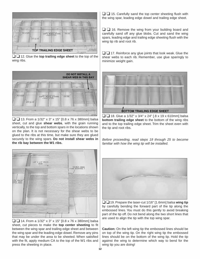
❏ ❏ 19. Prepare the laser-cut 1/16" [1.6mm] balsa wing tipby carefully bending the forward part of the tip along theembossed lines. You must do this gently to avoid breakingpart of the tip off. Do not bend along the two short lines thatare used to align the tip with the top wing spar.
Caution: On the left wing tip the embossed lines should beon top of the wing tip. On the right wing tip the embossedlines should be on the bottom of the wing tip. Hold the tipagainst the wing to determine which way to bend for thewing tip you are doing!
12
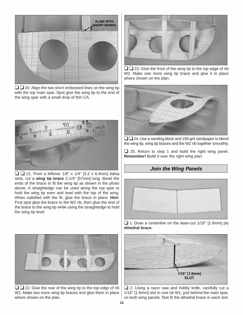
❏ ❏ 20. Align the two short embossed lines on the wing tipwith the top main spar. Spot glue the wing tip to the end ofthe wing spar with a small drop of thin CA.
❏ ❏ 21. From a leftover 1/8" x 1/4" [3.2 x 6.4mm] balsastick, cut a wing tip brace 2-1/4" [57mm] long. Bevel theends of the brace to fit the wing tip as shown in the photoabove. A straightedge can be used along the top spar tohold the wing tip even and level with the top of the wing.When satisfied with the fit, glue the brace in place. Hint:First spot glue the brace to the W2 rib, then glue the end ofthe brace to the wing tip while using the straightedge to holdthe wing tip level.
❏ ❏ 22. Glue the rear of the wing tip to the top edge of ribW2. Make two more wing tip braces and glue them in placewhere shown on the plan.
❏ ❏ 23. Glue the front of the wing tip to the top edge of ribW2. Make one more wing tip brace and glue it in placewhere shown on the plan.
❏ ❏ 24. Use a sanding block and 150-grit sandpaper to blendthe wing tip, wing tip braces and the W2 rib together smoothly.
❏ 25. Return to step 1 and build the right wing panel.Remember! Build it over the right wing plan.
❏ 1. Draw a centerline on the laser-cut 1/16" [1.6mm] plydihedral brace.
❏ 2. Using a razor saw and hobby knife, carefully cut a1/16" [1.6mm] slot in root rib W1, just behind the main spar,on both wing panels. Test fit the dihedral brace in each slot.
Join the Wing Panels
13
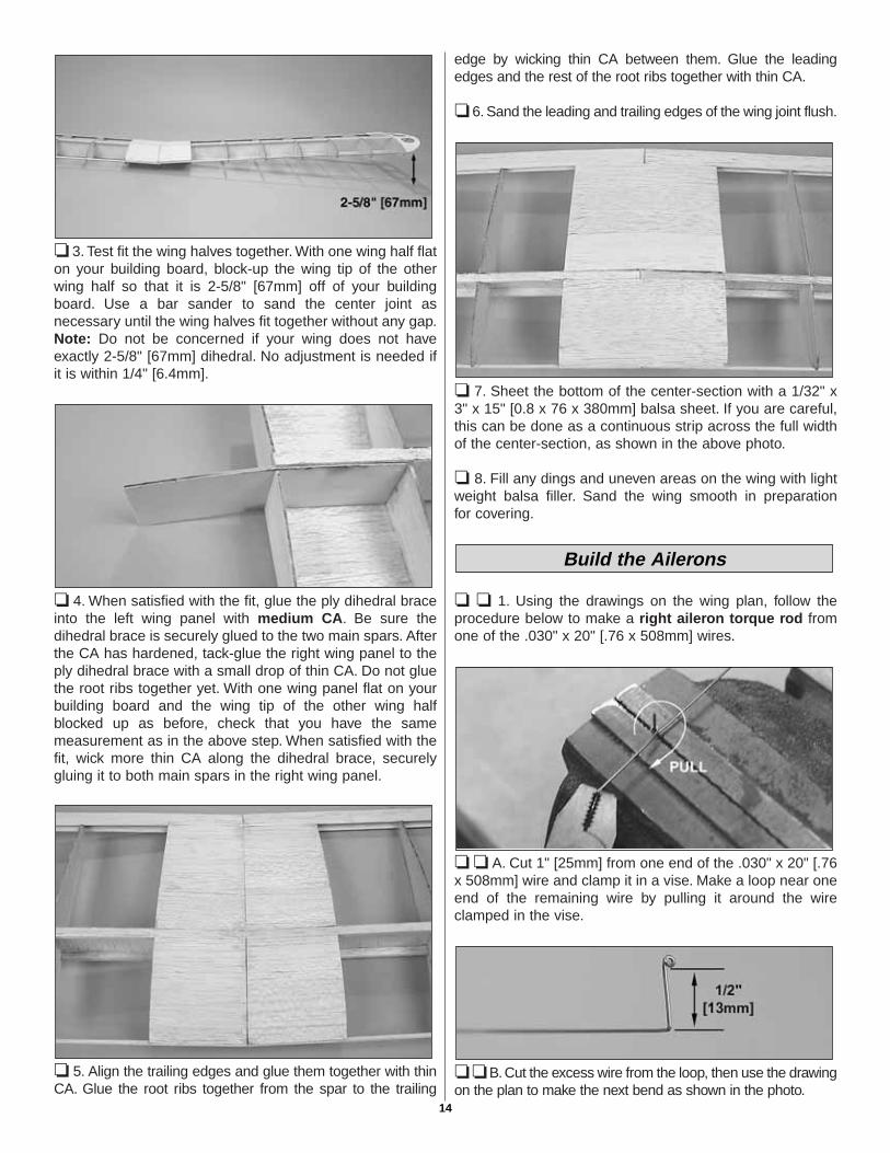
❏ 3. Test fit the wing halves together. With one wing half flaton your building board, block-up the wing tip of the otherwing half so that it is 2-5/8" [67mm] off of your buildingboard. Use a bar sander to sand the center joint asnecessary until the wing halves fit together without any gap.Note: Do not be concerned if your wing does not haveexactly 2-5/8" [67mm] dihedral. No adjustment is needed ifit is within 1/4" [6.4mm].
❏ 4. When satisfied with the fit, glue the ply dihedral braceinto the left wing panel with medium CA. Be sure thedihedral brace is securely glued to the two main spars. Afterthe CA has hardened, tack-glue the right wing panel to theply dihedral brace with a small drop of thin CA. Do not gluethe root ribs together yet. With one wing panel flat on yourbuilding board and the wing tip of the other wing halfblocked up as before, check that you have the samemeasurement as in the above step. When satisfied with thefit, wick more thin CA along the dihedral brace, securelygluing it to both main spars in the right wing panel.
❏ 5. Align the trailing edges and glue them together with thinCA. Glue the root ribs together from the spar to the trailing
edge by wicking thin CA between them. Glue the leadingedges and the rest of the root ribs together with thin CA.
❏ 6. Sand the leading and trailing edges of the wing joint flush.
❏ 7. Sheet the bottom of the center-section with a 1/32" x3" x 15" [0.8 x 76 x 380mm] balsa sheet. If you are careful,this can be done as a continuous strip across the full widthof the center-section, as shown in the above photo.
❏ 8. Fill any dings and uneven areas on the wing with lightweight balsa filler. Sand the wing smooth in preparationfor covering.
❏ ❏ 1. Using the drawings on the wing plan, follow theprocedure below to make a right aileron torque rod fromone of the .030" x 20" [.76 x 508mm] wires.
❏ ❏ A. Cut 1" [25mm] from one end of the .030" x 20" [.76x 508mm] wire and clamp it in a vise. Make a loop near oneend of the remaining wire by pulling it around the wireclamped in the vise.
❏ ❏ B. Cut the excess wire from the loop, then use the drawingon the plan to make the next bend as shown in the photo.
Build the Ailerons
14
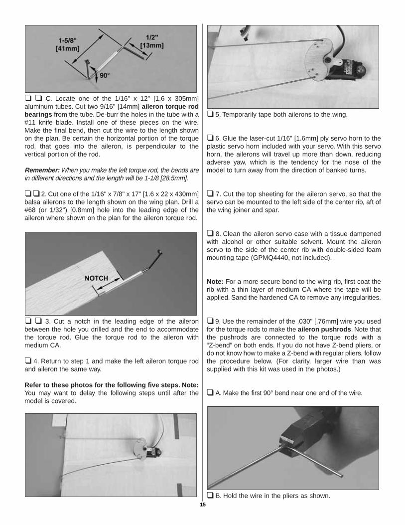
❏ ❏ C. Locate one of the 1/16" x 12" [1.6 x 305mm]aluminum tubes. Cut two 9/16" [14mm] aileron torque rodbearings from the tube. De-burr the holes in the tube with a#11 knife blade. Install one of these pieces on the wire.Make the final bend, then cut the wire to the length shownon the plan. Be certain the horizontal portion of the torquerod, that goes into the aileron, is perpendicular to thevertical portion of the rod.
Remember: When you make the left torque rod, the bends arein different directions and the length will be 1-1/8 [28.5mm].
❏ ❏ 2. Cut one of the 1/16" x 7/8" x 17" [1.6 x 22 x 430mm]balsa ailerons to the length shown on the wing plan. Drill a#68 (or 1/32") [0.8mm] hole into the leading edge of theaileron where shown on the plan for the aileron torque rod.
❏ ❏ 3. Cut a notch in the leading edge of the aileronbetween the hole you drilled and the end to accommodatethe torque rod. Glue the torque rod to the aileron withmedium CA.
❏ 4. Return to step 1 and make the left aileron torque rodand aileron the same way.
Refer to these photos for the following five steps. Note:You may want to delay the following steps until after themodel is covered.
❏ 5. Temporarily tape both ailerons to the wing.
❏ 6. Glue the laser-cut 1/16" [1.6mm] ply servo horn to theplastic servo horn included with your servo. With this servohorn, the ailerons will travel up more than down, reducingadverse yaw, which is the tendency for the nose of themodel to turn away from the direction of banked turns.
❏ 7. Cut the top sheeting for the aileron servo, so that theservo can be mounted to the left side of the center rib, aft ofthe wing joiner and spar.
❏ 8. Clean the aileron servo case with a tissue dampenedwith alcohol or other suitable solvent. Mount the aileronservo to the side of the center rib with double-sided foammounting tape (GPMQ4440, not included).
Note: For a more secure bond to the wing rib, first coat therib with a thin layer of medium CA where the tape will beapplied. Sand the hardened CA to remove any irregularities.
❏ 9. Use the remainder of the .030" [.76mm] wire you usedfor the torque rods to make the aileron pushrods. Note thatthe pushrods are connected to the torque rods with a “Z-bend” on both ends. If you do not have Z-bend pliers, ordo not know how to make a Z-bend with regular pliers, followthe procedure below. (For clarity, larger wire than wassupplied with this kit was used in the photos.)
❏ A. Make the first 90° bend near one end of the wire.
❏ B. Hold the wire in the pliers as shown.15
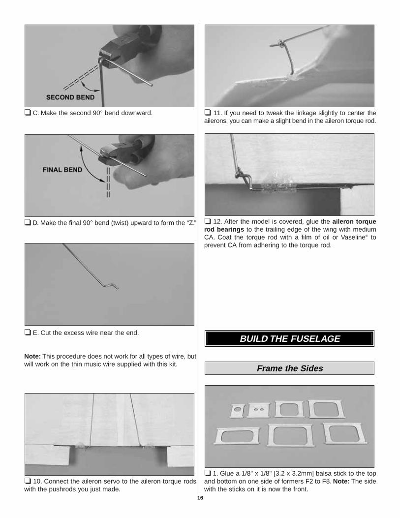
❏ C. Make the second 90° bend downward.
❏ D. Make the final 90° bend (twist) upward to form the “Z.”
❏ E. Cut the excess wire near the end.
Note: This procedure does not work for all types of wire, butwill work on the thin music wire supplied with this kit.
❏ 10. Connect the aileron servo to the aileron torque rodswith the pushrods you just made.
❏ 11. If you need to tweak the linkage slightly to center theailerons, you can make a slight bend in the aileron torque rod.
❏ 12. After the model is covered, glue the aileron torquerod bearings to the trailing edge of the wing with mediumCA. Coat the torque rod with a film of oil or Vaseline® toprevent CA from adhering to the torque rod.
❏ 1. Glue a 1/8" x 1/8" [3.2 x 3.2mm] balsa stick to the topand bottom on one side of formers F2 to F8. Note: The sidewith the sticks on it is now the front.
Frame the Sides
BUILD THE FUSELAGE
16
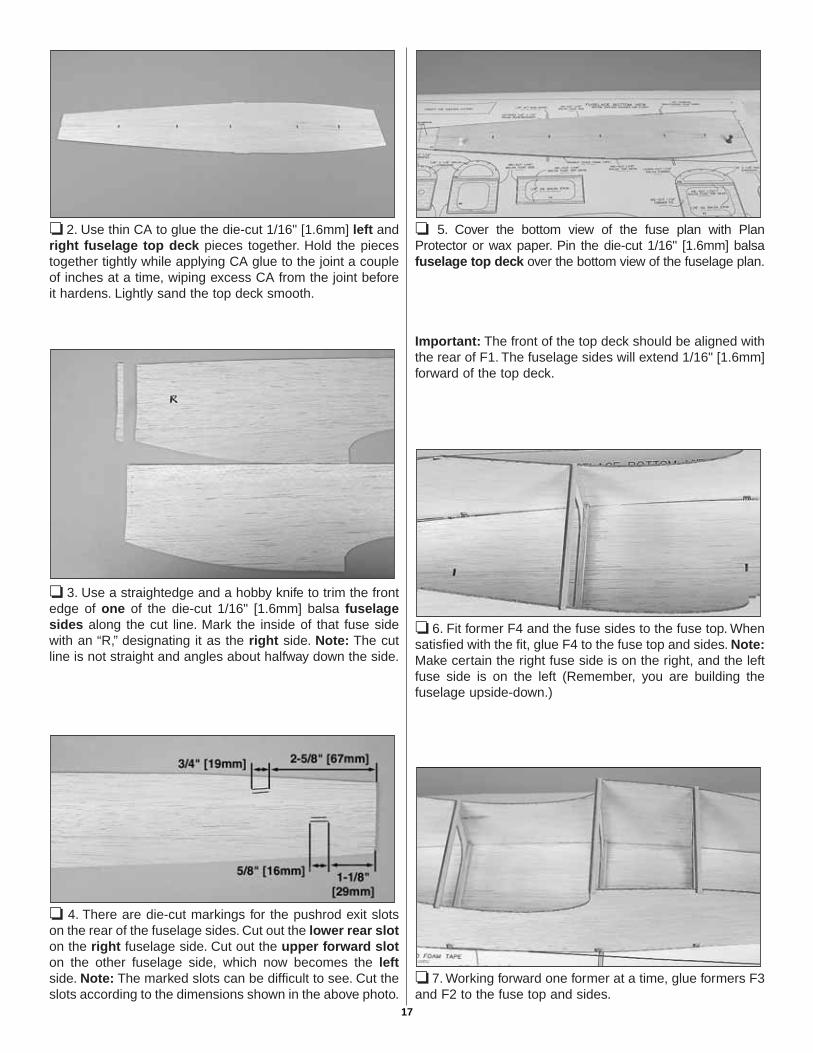
❏ 2. Use thin CA to glue the die-cut 1/16" [1.6mm] left andright fuselage top deck pieces together. Hold the piecestogether tightly while applying CA glue to the joint a coupleof inches at a time, wiping excess CA from the joint beforeit hardens. Lightly sand the top deck smooth.
❏ 3. Use a straightedge and a hobby knife to trim the frontedge of one of the die-cut 1/16" [1.6mm] balsa fuselagesides along the cut line. Mark the inside of that fuse sidewith an “R,” designating it as the right side. Note: The cutline is not straight and angles about halfway down the side.
❏ 4. There are die-cut markings for the pushrod exit slotson the rear of the fuselage sides. Cut out the lower rear sloton the right fuselage side. Cut out the upper forward sloton the other fuselage side, which now becomes the leftside. Note: The marked slots can be difficult to see. Cut theslots according to the dimensions shown in the above photo.
❏ 5. Cover the bottom view of the fuse plan with PlanProtector or wax paper. Pin the die-cut 1/16" [1.6mm] balsafuselage top deck over the bottom view of the fuselage plan.
Important: The front of the top deck should be aligned withthe rear of F1. The fuselage sides will extend 1/16" [1.6mm]forward of the top deck.
❏ 6. Fit former F4 and the fuse sides to the fuse top. Whensatisfied with the fit, glue F4 to the fuse top and sides. Note:Make certain the right fuse side is on the right, and the leftfuse side is on the left (Remember, you are building thefuselage upside-down.)
❏ 7. Working forward one former at a time, glue formers F3and F2 to the fuse top and sides.
17
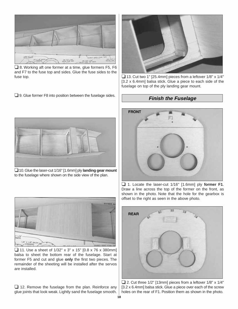
❏ 8. Working aft one former at a time, glue formers F5, F6and F7 to the fuse top and sides. Glue the fuse sides to thefuse top.
❏ 9. Glue former F8 into position between the fuselage sides.
❏ 10.Glue the laser-cut 1/16" [1.6mm] ply landing gear mountto the fuselage where shown on the side view of the plan.
❏ 11. Use a sheet of 1/32" x 3" x 15" [0.8 x 76 x 380mm]balsa to sheet the bottom rear of the fuselage. Start atformer F5 and cut and glue only the first two pieces. Theremainder of the sheeting will be installed after the servosare installed.
❏ 12. Remove the fuselage from the plan. Reinforce anyglue joints that look weak. Lightly sand the fuselage smooth.
❏ 13. Cut two 1" [25.4mm] pieces from a leftover 1/8" x 1/4"[3.2 x 6.4mm] balsa stick. Glue a piece to each side of thefuselage on top of the ply landing gear mount.
❏ 1. Locate the laser-cut 1/16" [1.6mm] ply former F1.Draw a line across the top of the former on the front, asshown in the photo. Note that the hole for the gearbox isoffset to the right as seen in the above photo.
❏ 2. Cut three 1/2" [13mm] pieces from a leftover 1/8" x 1/4"[3.2 x 6.4mm] balsa stick. Glue a piece over each of the screwholes on the rear of F1. Position them as shown in the photo.
Finish the Fuselage
18
❏ 3. Cut four 1" [25.4mm] pieces from a leftover 1/8" x 1/4"[3.2 x 6.4mm] balsa stick.
Before proceeding, read steps 4 thru 9. This will give you abetter understanding of how to proceed.
❏ 4. Check the fit of former F1 to the front of the fuselage.The top deck should end 1/16" [1.6mm] aft of the frontedges of the fuselage sides. With F1 in place, the top deckshould be against the rear of F1. Note: It may be necessaryto trim the fuse sides to match the width of the firewall.
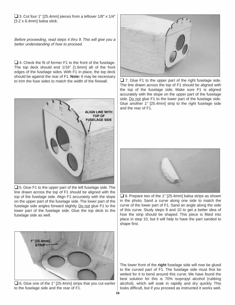
❏ 5. Glue F1 to the upper part of the left fuselage side. Theline drawn across the top of F1 should be aligned with thetop of the fuselage side. Align F1 accurately with the slopeon the upper part of the fuselage side. The lower part of thefuselage side angles forward slightly. Do not glue F1 to thelower part of the fuselage side. Glue the top deck to thefuselage side as well.
❏ 6. Glue one of the 1" [25.4mm] strips that you cut earlierto the fuselage side and the rear of F1.
❏ 7. Glue F1 to the upper part of the right fuselage side.The line drawn across the top of F1 should be aligned withthe top of the fuselage side. Make sure F1 is alignedaccurately with the slope on the upper part of the fuselageside. Do not glue F1 to the lower part of the fuselage side.Glue another 1" [25.4mm] strip to the right fuselage sideand the rear of F1.
❏ 8. Prepare two of the 1" [25.4mm] balsa strips as shownin the photo. Sand a curve along one side to match thecurve of the lower part of F1. Sand an angle along the sideof this curve. Study steps 9 and 10 to get a better idea ofhow the strip should be shaped. This piece is fitted intoplace in step 10, but it will help to have the part sanded toshape first.
The lower front of the right fuselage side will now be gluedto the curved part of F1. The fuselage side must first bewetted for it to bend around this curve. We have found thebest solution for this is 70% isopropyl alcohol (rubbingalcohol), which will soak in rapidly and dry quickly. Thislooks difficult, but if you proceed as instructed it works well.
19
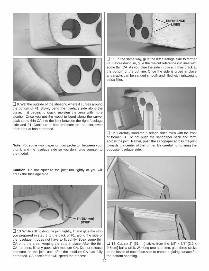
❏ 9. Wet the outside of the sheeting where it curves aroundthe bottom of F1. Slowly bend the fuselage side along thecurve. If it begins to crack, moisten the area with morealcohol. Once you get the wood to bend along the curve,soak some thin CA into the joint between the right fuselageside and F1. Continue to hold pressure on the joint, evenafter the CA has hardened.
Note: Put some wax paper or plan protector between yourthumb and the fuselage side so you don’t glue yourself tothe model.
Caution: Do not squeeze the joint too tightly or you willbreak the fuselage side.
❏ 10. While still holding the joint tightly, fit and glue the stripyou prepared in step 8 to the back of F1, along the side ofthe fuselage. It does not have to fit tightly. Soak some thinCA onto the area, keeping the strip in place. After the thinCA hardens, fill any gaps with medium CA. Do not releasepressure on the joint until after the medium CA has fullyhardened. CA accelerator will speed the process.
❏ 11. In the same way, glue the left fuselage side to formerF1. Before doing so, glue the die-cut reference cut lines withsome thin CA. As you glue the side in place, it may crack atthe bottom of the cut line. Once the side is glued in placeany cracks can be sanded smooth and filled with lightweightbalsa filler.
❏ 12. Carefully sand the fuselage sides even with the frontof former F1. Do not push the sandpaper back and forthacross the joint. Rather, push the sandpaper across the jointtowards the center of the former. Be careful not to snag theopposite fuselage side.
❏ 13. Cut six 2" [51mm] sticks from the 1/8" x 3/8" [3.2 x9.6mm] balsa stick. Working one at a time, glue three sticksto the inside of each fuse side to create a gluing surface forthe bottom sheeting.
20

❏ 14. Sand the sticks flat so that the bottom sheeting canbe glued in place.
❏ 15. Using the 1/16" x 3" [1.6 x 76mm] balsa sheet, sheetthe bottom front of the fuselage. Start by gluing a sheetbeginning at the ply landing gear mount.
❏ 16. Sand the contour of the fuselage front to blend intoformer F1. Fill any gaps with lightweight balsa filler.
❏ 17. Place the fuselage upside-down over the bottom viewof the plan. Mark the location of formers F2A, F3A, F4A,F5A, F6A and F7A on the left and right fuselage sides.Transfer the marks to the top deck of the fuselage. Note onthe side view that formers F4A and F5A are not located overF4 and F5.
❏ 18. Glue the die-cut 1/16" [1.6mm] balsa formers F2Athru F8A to the fuselage top deck. Formers F2A, F3A, F6A,F7A and F8A are glued perpendicular to the top deck. Usethe die-cut 1/16" [1.6mm] balsa F3A gauge to establish thecorrect angle of F4A. Use the die-cut 1/16" [1.6mm]dihedral gauge to set the angle of F5A.
❏ 19. Using three 1/8" x 1/8" x 24" [3.2 x 3.2 x 610mm]balsa sticks, cut, fit and glue the stringers to the forward partof the fuselage. Start with the bottom stringer, which goesfrom F1 to F5A. Use the remainder of this stick to do thestringer above it. Use the third stick to do the top centerstringer, saving the remainder of the stick for the top stringeron the aft part of the fuselage.
❏ 20. Using five 1/8" x 1/8" x 24" [3.2 x 3.2 x 610mm] balsasticks, cut, fit and glue the stringers to the aft part of thefuselage. Start with the two bottom stringers on each side,which go from F5 to the rear of F8.
21
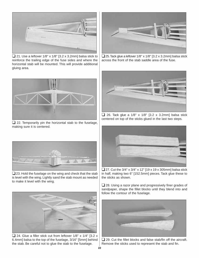
❏ 21. Use a leftover 1/8" x 1/8" [3.2 x 3.2mm] balsa stick toreinforce the trailing edge of the fuse sides and where thehorizontal stab will be mounted. This will provide additionalgluing area.
❏ 22. Temporarily pin the horizontal stab to the fuselage,making sure it is centered.
❏ 23. Hold the fuselage on the wing and check that the stabis level with the wing. Lightly sand the stab mount as neededto make it level with the wing.
❏ 24. Glue a filler stick cut from leftover 1/8" x 1/4" [3.2 x6.4mm] balsa to the top of the fuselage, 3/16" [5mm] behindthe stab. Be careful not to glue the stab to the fuselage.
❏ 25.Tack glue a leftover 1/8" x 1/8" [3.2 x 3.2mm] balsa stickacross the front of the stab saddle area of the fuse.
❏ 26. Tack glue a 1/8" x 1/8" [3.2 x 3.2mm] balsa stickcentered on top of the sticks glued in the last two steps.
❏ 27. Cut the 3/4" x 3/4" x 12" [19 x 19 x 305mm] balsa stickin half, making two 6" [152.5mm] pieces. Tack glue these tothe sticks as shown.
❏ 28. Using a razor plane and progressively finer grades ofsandpaper, shape the fillet blocks until they blend into andfollow the contour of the fuselage.
❏ 29. Cut the fillet blocks and false stab/fin off the aircraft.Remove the sticks used to represent the stab and fin.
22
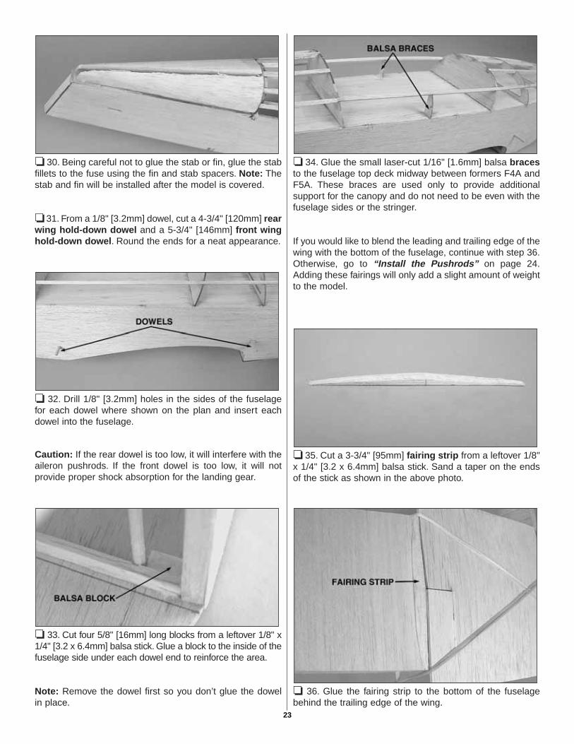
❏ 30. Being careful not to glue the stab or fin, glue the stabfillets to the fuse using the fin and stab spacers. Note: Thestab and fin will be installed after the model is covered.
❏ 31. From a 1/8" [3.2mm] dowel, cut a 4-3/4" [120mm] rearwing hold-down dowel and a 5-3/4" [146mm] front winghold-down dowel. Round the ends for a neat appearance.
❏ 32. Drill 1/8" [3.2mm] holes in the sides of the fuselagefor each dowel where shown on the plan and insert eachdowel into the fuselage.
Caution: If the rear dowel is too low, it will interfere with theaileron pushrods. If the front dowel is too low, it will notprovide proper shock absorption for the landing gear.
❏ 33. Cut four 5/8" [16mm] long blocks from a leftover 1/8" x1/4" [3.2 x 6.4mm] balsa stick. Glue a block to the inside of thefuselage side under each dowel end to reinforce the area.
Note: Remove the dowel first so you don’t glue the dowelin place.
❏ 34. Glue the small laser-cut 1/16" [1.6mm] balsa bracesto the fuselage top deck midway between formers F4A andF5A. These braces are used only to provide additionalsupport for the canopy and do not need to be even with thefuselage sides or the stringer.
If you would like to blend the leading and trailing edge of thewing with the bottom of the fuselage, continue with step 36.Otherwise, go to “Install the Pushrods” on page 24.Adding these fairings will only add a slight amount of weightto the model.
❏ 35. Cut a 3-3/4" [95mm] fairing strip from a leftover 1/8"x 1/4" [3.2 x 6.4mm] balsa stick. Sand a taper on the endsof the stick as shown in the above photo.
❏ 36. Glue the fairing strip to the bottom of the fuselagebehind the trailing edge of the wing.
23
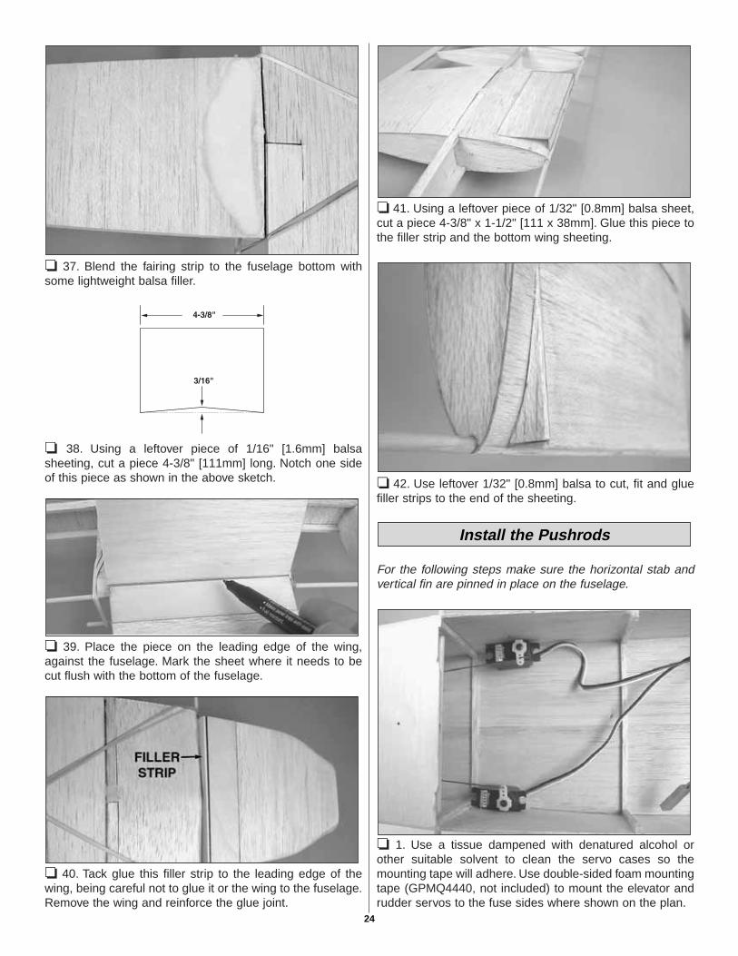
❏ 37. Blend the fairing strip to the fuselage bottom withsome lightweight balsa filler.
❏ 38. Using a leftover piece of 1/16" [1.6mm] balsasheeting, cut a piece 4-3/8" [111mm] long. Notch one sideof this piece as shown in the above sketch.
❏ 39. Place the piece on the leading edge of the wing,against the fuselage. Mark the sheet where it needs to becut flush with the bottom of the fuselage.
❏ 40. Tack glue this filler strip to the leading edge of thewing, being careful not to glue it or the wing to the fuselage.Remove the wing and reinforce the glue joint.
❏ 41. Using a leftover piece of 1/32" [0.8mm] balsa sheet,cut a piece 4-3/8" x 1-1/2" [111 x 38mm]. Glue this piece tothe filler strip and the bottom wing sheeting.
❏ 42. Use leftover 1/32" [0.8mm] balsa to cut, fit and gluefiller strips to the end of the sheeting.
For the following steps make sure the horizontal stab andvertical fin are pinned in place on the fuselage.
❏ 1. Use a tissue dampened with denatured alcohol orother suitable solvent to clean the servo cases so themounting tape will adhere. Use double-sided foam mountingtape (GPMQ4440, not included) to mount the elevator andrudder servos to the fuse sides where shown on the plan.
Install the Pushrods
24
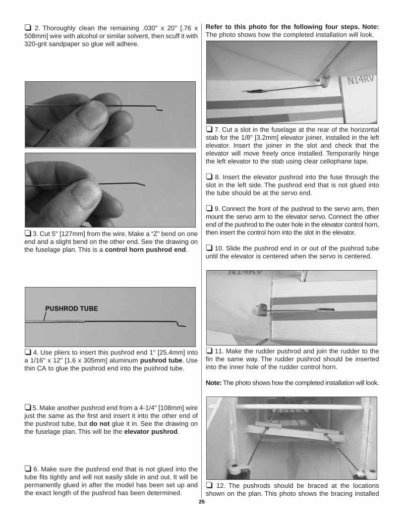
❏ 2. Thoroughly clean the remaining .030" x 20" [.76 x508mm] wire with alcohol or similar solvent, then scuff it with320-grit sandpaper so glue will adhere.
❏ 3. Cut 5" [127mm] from the wire. Make a “Z” bend on oneend and a slight bend on the other end. See the drawing onthe fuselage plan. This is a control horn pushrod end.
❏ 4. Use pliers to insert this pushrod end 1" [25.4mm] intoa 1/16" x 12" [1.6 x 305mm] aluminum pushrod tube. Usethin CA to glue the pushrod end into the pushrod tube.
❏ 5. Make another pushrod end from a 4-1/4" [108mm] wirejust the same as the first and insert it into the other end ofthe pushrod tube, but do not glue it in. See the drawing onthe fuselage plan. This will be the elevator pushrod.
❏ 6. Make sure the pushrod end that is not glued into thetube fits tightly and will not easily slide in and out. It will bepermanently glued in after the model has been set up andthe exact length of the pushrod has been determined.
Refer to this photo for the following four steps. Note:The photo shows how the completed installation will look.
❏ 7. Cut a slot in the fuselage at the rear of the horizontalstab for the 1/8" [3.2mm] elevator joiner, installed in the leftelevator. Insert the joiner in the slot and check that theelevator will move freely once installed. Temporarily hingethe left elevator to the stab using clear cellophane tape.
❏ 8. Insert the elevator pushrod into the fuse through theslot in the left side. The pushrod end that is not glued intothe tube should be at the servo end.
❏ 9. Connect the front of the pushrod to the servo arm, thenmount the servo arm to the elevator servo. Connect the otherend of the pushrod to the outer hole in the elevator control horn,then insert the control horn into the slot in the elevator.
❏ 10. Slide the pushrod end in or out of the pushrod tubeuntil the elevator is centered when the servo is centered.
❏ 11. Make the rudder pushrod and join the rudder to thefin the same way. The rudder pushrod should be insertedinto the inner hole of the rudder control horn.
Note: The photo shows how the completed installation will look.
❏ 12. The pushrods should be braced at the locationsshown on the plan. This photo shows the bracing installed
25
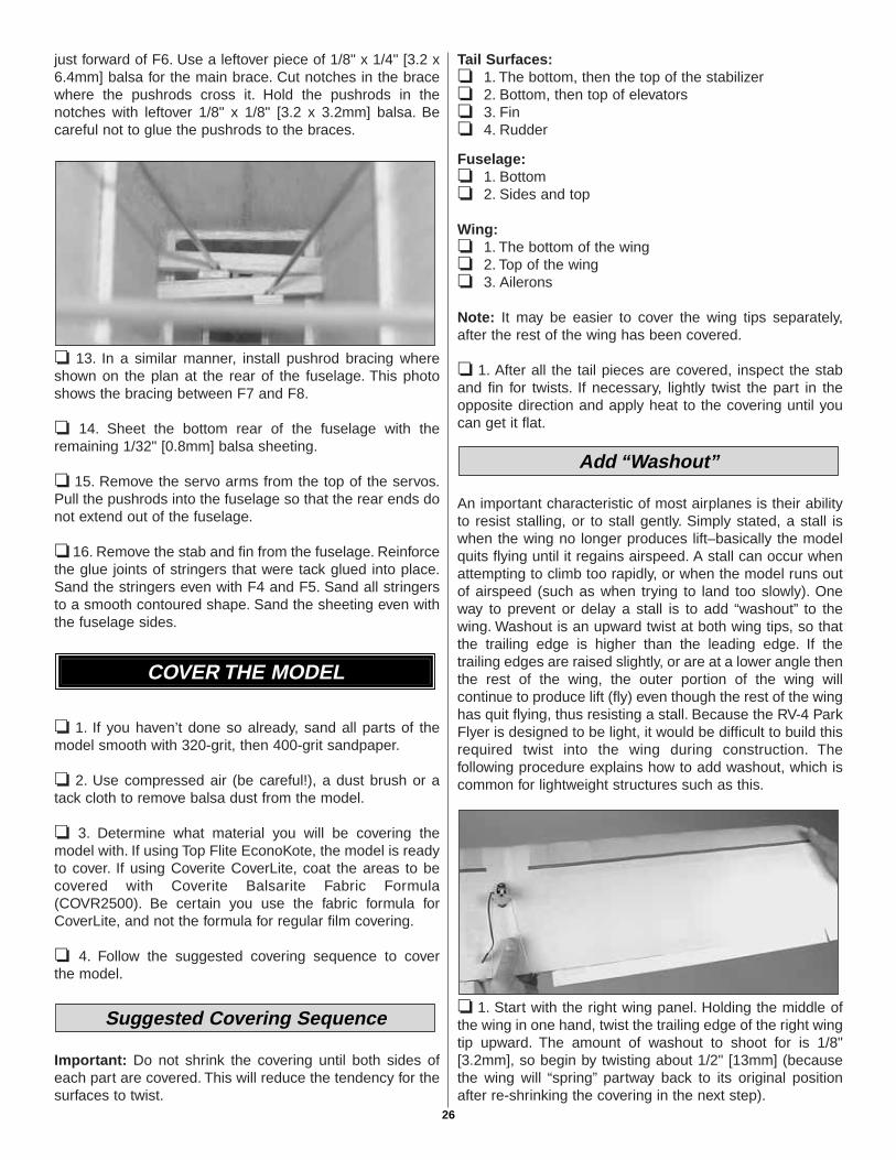
just forward of F6. Use a leftover piece of 1/8" x 1/4" [3.2 x6.4mm] balsa for the main brace. Cut notches in the bracewhere the pushrods cross it. Hold the pushrods in thenotches with leftover 1/8" x 1/8" [3.2 x 3.2mm] balsa. Becareful not to glue the pushrods to the braces.
❏ 13. In a similar manner, install pushrod bracing whereshown on the plan at the rear of the fuselage. This photoshows the bracing between F7 and F8.
❏ 14. Sheet the bottom rear of the fuselage with theremaining 1/32" [0.8mm] balsa sheeting.
❏ 15. Remove the servo arms from the top of the servos.Pull the pushrods into the fuselage so that the rear ends donot extend out of the fuselage.
❏ 16. Remove the stab and fin from the fuselage. Reinforcethe glue joints of stringers that were tack glued into place.Sand the stringers even with F4 and F5. Sand all stringersto a smooth contoured shape. Sand the sheeting even withthe fuselage sides.
❏ 1. If you haven’t done so already, sand all parts of themodel smooth with 320-grit, then 400-grit sandpaper.
❏ 2. Use compressed air (be careful!), a dust brush or atack cloth to remove balsa dust from the model.
❏ 3. Determine what material you will be covering themodel with. If using Top Flite EconoKote, the model is readyto cover. If using Coverite CoverLite, coat the areas to becovered with Coverite Balsarite Fabric Formula(COVR2500). Be certain you use the fabric formula forCoverLite, and not the formula for regular film covering.
❏ 4. Follow the suggested covering sequence to cover the model.
Important: Do not shrink the covering until both sides ofeach part are covered. This will reduce the tendency for thesurfaces to twist.
Tail Surfaces:❏ 1. The bottom, then the top of the stabilizer❏ 2. Bottom, then top of elevators❏ 3. Fin❏ 4. Rudder
Fuselage:❏ 1. Bottom❏ 2. Sides and top
Wing:❏ 1. The bottom of the wing❏ 2. Top of the wing❏ 3. Ailerons
Note: It may be easier to cover the wing tips separately,after the rest of the wing has been covered.
❏ 1. After all the tail pieces are covered, inspect the staband fin for twists. If necessary, lightly twist the part in theopposite direction and apply heat to the covering until youcan get it flat.
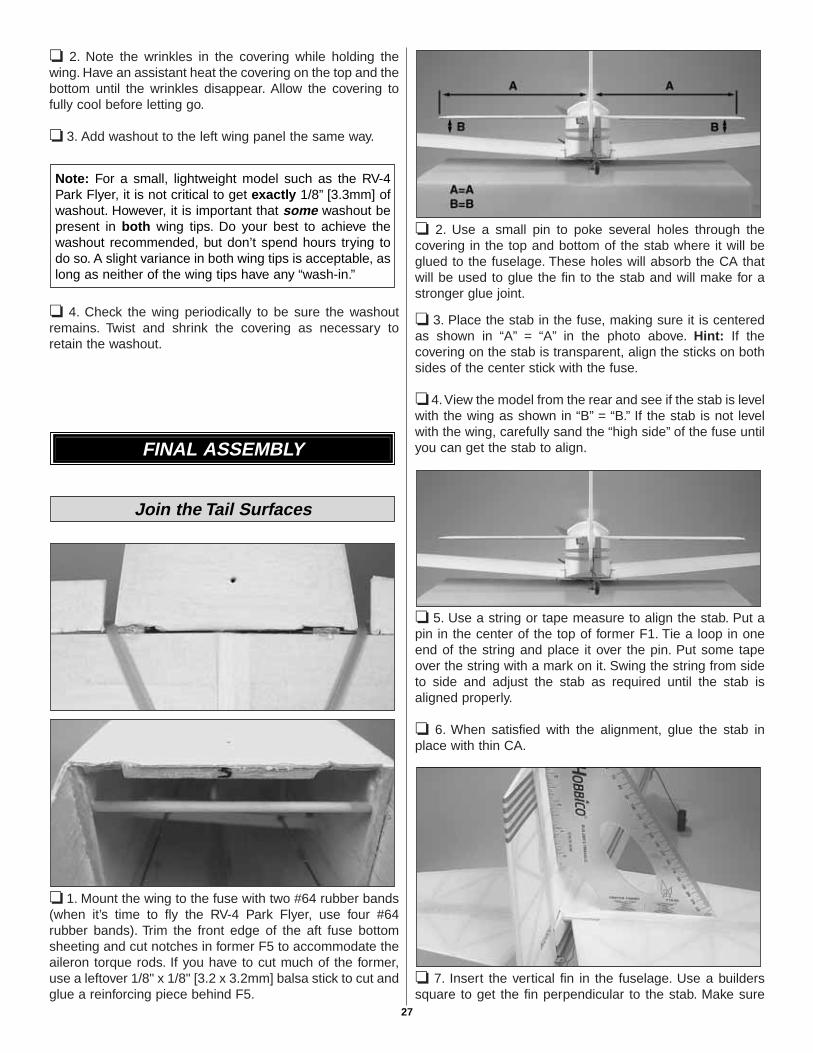
An important characteristic of most airplanes is their abilityto resist stalling, or to stall gently. Simply stated, a stall iswhen the wing no longer produces lift–basically the modelquits flying until it regains airspeed. A stall can occur whenattempting to climb too rapidly, or when the model runs outof airspeed (such as when trying to land too slowly). Oneway to prevent or delay a stall is to add “washout” to thewing. Washout is an upward twist at both wing tips, so thatthe trailing edge is higher than the leading edge. If thetrailing edges are raised slightly, or are at a lower angle thenthe rest of the wing, the outer portion of the wing willcontinue to produce lift (fly) even though the rest of the winghas quit flying, thus resisting a stall. Because the RV-4 ParkFlyer is designed to be light, it would be difficult to build thisrequired twist into the wing during construction. Thefollowing procedure explains how to add washout, which iscommon for lightweight structures such as this.
❏ 1. Start with the right wing panel. Holding the middle ofthe wing in one hand, twist the trailing edge of the right wingtip upward. The amount of washout to shoot for is 1/8"[3.2mm], so begin by twisting about 1/2" [13mm] (becausethe wing will “spring” partway back to its original positionafter re-shrinking the covering in the next step).
Add “Washout”
Suggested Covering Sequence
COVER THE MODEL
26
❏ 2. Note the wrinkles in the covering while holding thewing. Have an assistant heat the covering on the top and thebottom until the wrinkles disappear. Allow the covering tofully cool before letting go.
❏ 3. Add washout to the left wing panel the same way.
❏ 4. Check the wing periodically to be sure the washoutremains. Twist and shrink the covering as necessary toretain the washout.
❏ 1. Mount the wing to the fuse with two #64 rubber bands(when it’s time to fly the RV-4 Park Flyer, use four #64rubber bands). Trim the front edge of the aft fuse bottomsheeting and cut notches in former F5 to accommodate theaileron torque rods. If you have to cut much of the former,use a leftover 1/8" x 1/8" [3.2 x 3.2mm] balsa stick to cut andglue a reinforcing piece behind F5.
❏ 2. Use a small pin to poke several holes through thecovering in the top and bottom of the stab where it will beglued to the fuselage. These holes will absorb the CA thatwill be used to glue the fin to the stab and will make for astronger glue joint.
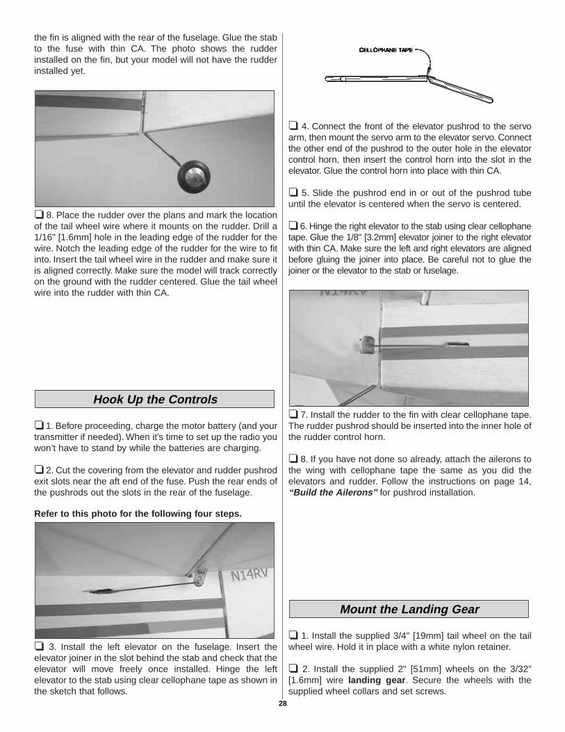
❏ 3. Place the stab in the fuse, making sure it is centeredas shown in “A” = “A” in the photo above. Hint: If thecovering on the stab is transparent, align the sticks on bothsides of the center stick with the fuse.
❏ 4.View the model from the rear and see if the stab is levelwith the wing as shown in “B” = “B.” If the stab is not levelwith the wing, carefully sand the “high side” of the fuse untilyou can get the stab to align.
❏ 5. Use a string or tape measure to align the stab. Put apin in the center of the top of former F1. Tie a loop in oneend of the string and place it over the pin. Put some tapeover the string with a mark on it. Swing the string from sideto side and adjust the stab as required until the stab isaligned properly.
❏ 6. When satisfied with the alignment, glue the stab inplace with thin CA.
❏ 7. Insert the vertical fin in the fuselage. Use a builderssquare to get the fin perpendicular to the stab. Make sure
Join the Tail Surfaces
FINAL ASSEMBLY
Note: For a small, lightweight model such as the RV-4Park Flyer, it is not critical to get exactly 1/8” [3.3mm] ofwashout. However, it is important that some washout bepresent in both wing tips. Do your best to achieve thewashout recommended, but don’t spend hours trying todo so. A slight variance in both wing tips is acceptable, aslong as neither of the wing tips have any “wash-in.”
27
the fin is aligned with the rear of the fuselage. Glue the stabto the fuse with thin CA. The photo shows the rudderinstalled on the fin, but your model will not have the rudderinstalled yet.
❏ 8. Place the rudder over the plans and mark the locationof the tail wheel wire where it mounts on the rudder. Drill a1/16" [1.6mm] hole in the leading edge of the rudder for thewire. Notch the leading edge of the rudder for the wire to fitinto. Insert the tail wheel wire in the rudder and make sure itis aligned correctly. Make sure the model will track correctlyon the ground with the rudder centered. Glue the tail wheelwire into the rudder with thin CA.
❏ 1. Before proceeding, charge the motor battery (and yourtransmitter if needed). When it’s time to set up the radio youwon’t have to stand by while the batteries are charging.
❏ 2. Cut the covering from the elevator and rudder pushrodexit slots near the aft end of the fuse. Push the rear ends ofthe pushrods out the slots in the rear of the fuselage.
Refer to this photo for the following four steps.
❏ 3. Install the left elevator on the fuselage. Insert theelevator joiner in the slot behind the stab and check that theelevator will move freely once installed. Hinge the leftelevator to the stab using clear cellophane tape as shown inthe sketch that follows.
❏ 4. Connect the front of the elevator pushrod to the servoarm, then mount the servo arm to the elevator servo. Connectthe other end of the pushrod to the outer hole in the elevatorcontrol horn, then insert the control horn into the slot in theelevator. Glue the control horn into place with thin CA.
❏ 5. Slide the pushrod end in or out of the pushrod tubeuntil the elevator is centered when the servo is centered.
❏ 6. Hinge the right elevator to the stab using clear cellophanetape. Glue the 1/8" [3.2mm] elevator joiner to the right elevatorwith thin CA. Make sure the left and right elevators are alignedbefore gluing the joiner into place. Be careful not to glue thejoiner or the elevator to the stab or fuselage.
❏ 7. Install the rudder to the fin with clear cellophane tape.The rudder pushrod should be inserted into the inner hole ofthe rudder control horn.
❏ 8. If you have not done so already, attach the ailerons tothe wing with cellophane tape the same as you did theelevators and rudder. Follow the instructions on page 14,“Build the Ailerons” for pushrod installation.
❏ 1. Install the supplied 3/4" [19mm] tail wheel on the tailwheel wire. Hold it in place with a white nylon retainer.
❏ 2. Install the supplied 2" [51mm] wheels on the 3/32"[1.6mm] wire landing gear. Secure the wheels with thesupplied wheel collars and set screws.
Mount the Landing Gear
Hook Up the Controls
28
❏ 3. Mount the landing gear to the fuse with a #14 rubberband on each side. Both rubber bands must be stretchedenough to wrap around the gear and dowel at least two times.
❏ 4. Cut four 1" [25.4mm] pieces from a leftover 1/8" x 1/8"[32. x 3.2mm] balsa stick. Glue the pieces in front of andbehind the landing gear as shown in the photo.
Follow these assembly instructions for the Great PlanesElectriFly motor and S-280 gear drive. If you are usinganother type of gear drive and motor, follow the instructionsthat came with the unit.
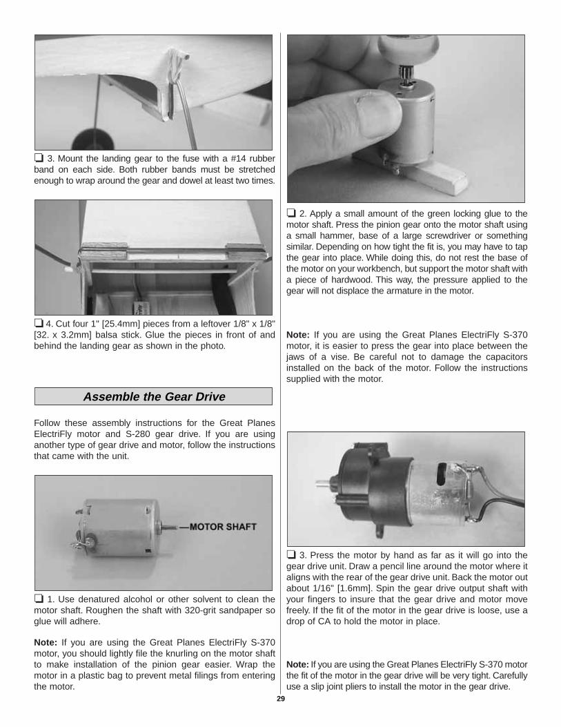
❏ 1. Use denatured alcohol or other solvent to clean themotor shaft. Roughen the shaft with 320-grit sandpaper soglue will adhere.
Note: If you are using the Great Planes ElectriFly S-370motor, you should lightly file the knurling on the motor shaftto make installation of the pinion gear easier. Wrap themotor in a plastic bag to prevent metal filings from enteringthe motor.
❏ 2. Apply a small amount of the green locking glue to themotor shaft. Press the pinion gear onto the motor shaft usinga small hammer, base of a large screwdriver or somethingsimilar. Depending on how tight the fit is, you may have to tapthe gear into place. While doing this, do not rest the base ofthe motor on your workbench, but support the motor shaft witha piece of hardwood. This way, the pressure applied to thegear will not displace the armature in the motor.
Note: If you are using the Great Planes ElectriFly S-370motor, it is easier to press the gear into place between thejaws of a vise. Be careful not to damage the capacitorsinstalled on the back of the motor. Follow the instructionssupplied with the motor.
❏ 3. Press the motor by hand as far as it will go into thegear drive unit. Draw a pencil line around the motor where italigns with the rear of the gear drive unit. Back the motor outabout 1/16" [1.6mm]. Spin the gear drive output shaft withyour fingers to insure that the gear drive and motor movefreely. If the fit of the motor in the gear drive is loose, use adrop of CA to hold the motor in place.
Note: If you are using the Great Planes ElectriFly S-370 motorthe fit of the motor in the gear drive will be very tight. Carefullyuse a slip joint pliers to install the motor in the gear drive.
Assemble the Gear Drive
29
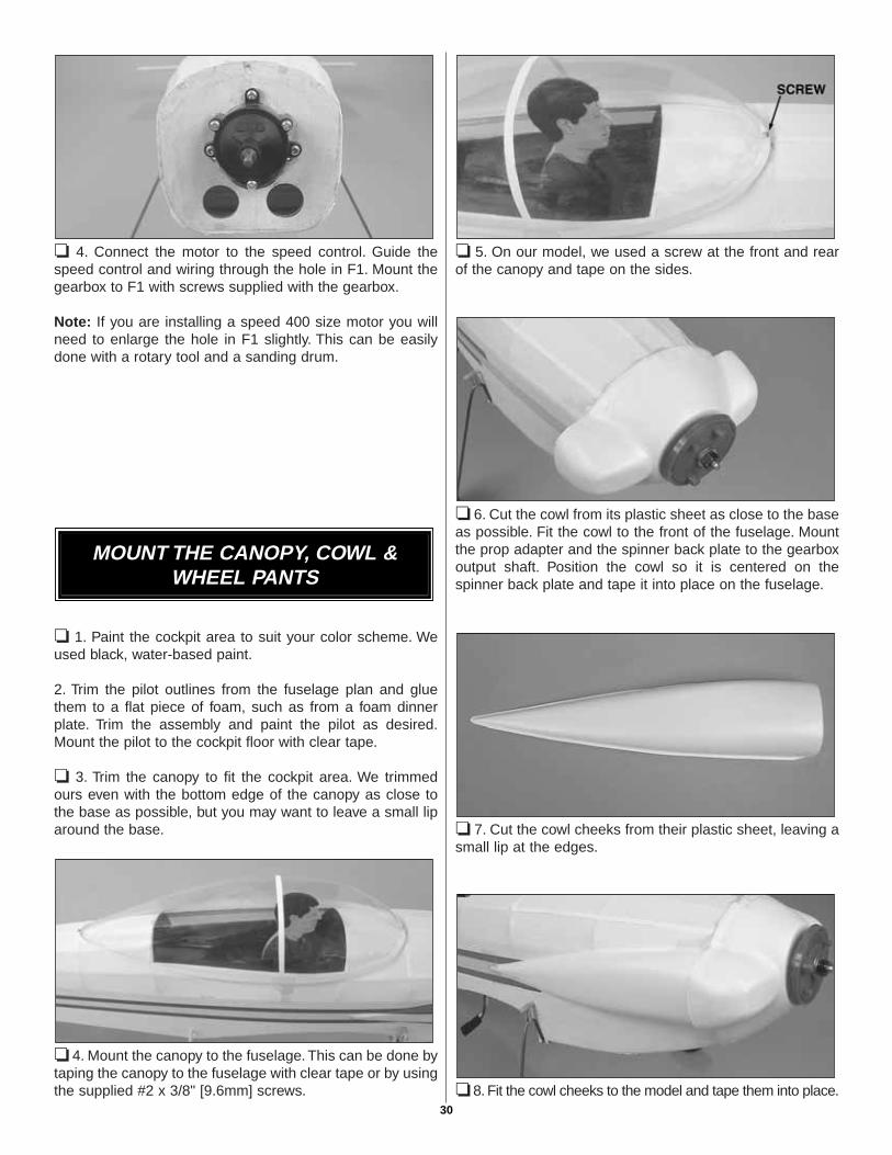
❏ 4. Connect the motor to the speed control. Guide thespeed control and wiring through the hole in F1. Mount thegearbox to F1 with screws supplied with the gearbox.
Note: If you are installing a speed 400 size motor you willneed to enlarge the hole in F1 slightly. This can be easilydone with a rotary tool and a sanding drum.
❏ 1. Paint the cockpit area to suit your color scheme. Weused black, water-based paint.
2. Trim the pilot outlines from the fuselage plan and gluethem to a flat piece of foam, such as from a foam dinnerplate. Trim the assembly and paint the pilot as desired.Mount the pilot to the cockpit floor with clear tape.
❏ 3. Trim the canopy to fit the cockpit area. We trimmedours even with the bottom edge of the canopy as close tothe base as possible, but you may want to leave a small liparound the base.
❏ 4. Mount the canopy to the fuselage. This can be done bytaping the canopy to the fuselage with clear tape or by usingthe supplied #2 x 3/8" [9.6mm] screws.
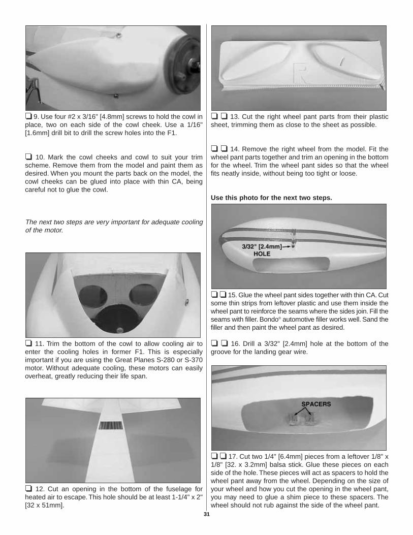
❏ 5. On our model, we used a screw at the front and rearof the canopy and tape on the sides.
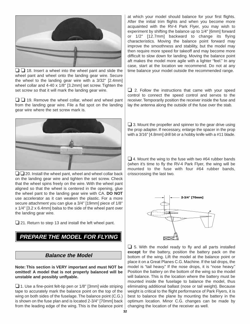
❏ 6. Cut the cowl from its plastic sheet as close to the baseas possible. Fit the cowl to the front of the fuselage. Mountthe prop adapter and the spinner back plate to the gearboxoutput shaft. Position the cowl so it is centered on thespinner back plate and tape it into place on the fuselage.
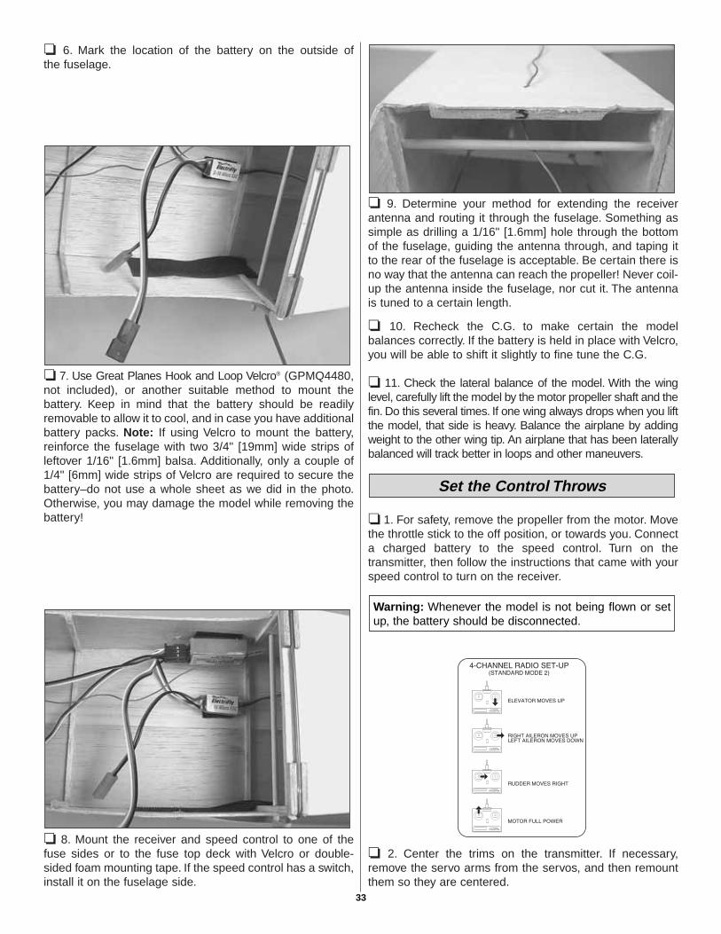
❏ 7. Cut the cowl cheeks from their plastic sheet, leaving asmall lip at the edges.
❏ 8. Fit the cowl cheeks to the model and tape them into place.
MOUNT THE CANOPY, COWL &WHEEL PANTS
30
❏ 9. Use four #2 x 3/16" [4.8mm] screws to hold the cowl inplace, two on each side of the cowl cheek. Use a 1/16"[1.6mm] drill bit to drill the screw holes into the F1.
❏ 10. Mark the cowl cheeks and cowl to suit your trimscheme. Remove them from the model and paint them asdesired. When you mount the parts back on the model, thecowl cheeks can be glued into place with thin CA, beingcareful not to glue the cowl.
The next two steps are very important for adequate coolingof the motor.
❏ 11. Trim the bottom of the cowl to allow cooling air toenter the cooling holes in former F1. This is especiallyimportant if you are using the Great Planes S-280 or S-370motor. Without adequate cooling, these motors can easilyoverheat, greatly reducing their life span.
❏ 12. Cut an opening in the bottom of the fuselage forheated air to escape. This hole should be at least 1-1/4" x 2"[32 x 51mm].
❏ ❏ 13. Cut the right wheel pant parts from their plasticsheet, trimming them as close to the sheet as possible.
❏ ❏ 14. Remove the right wheel from the model. Fit thewheel pant parts together and trim an opening in the bottomfor the wheel. Trim the wheel pant sides so that the wheelfits neatly inside, without being too tight or loose.
Use this photo for the next two steps.
❏ ❏ 15. Glue the wheel pant sides together with thin CA. Cutsome thin strips from leftover plastic and use them inside thewheel pant to reinforce the seams where the sides join. Fill theseams with filler. Bondo® automotive filler works well. Sand thefiller and then paint the wheel pant as desired.
❏ ❏ 16. Drill a 3/32" [2.4mm] hole at the bottom of thegroove for the landing gear wire.
❏ ❏ 17. Cut two 1/4" [6.4mm] pieces from a leftover 1/8" x1/8" [32. x 3.2mm] balsa stick. Glue these pieces on eachside of the hole. These pieces will act as spacers to hold thewheel pant away from the wheel. Depending on the size ofyour wheel and how you cut the opening in the wheel pant,you may need to glue a shim piece to these spacers. Thewheel should not rub against the side of the wheel pant.
31
❏ ❏ 18. Insert a wheel into the wheel pant and slide thewheel pant and wheel onto the landing gear wire. Securethe wheel to the landing gear wire with a 3/32" [2.4mm]wheel collar and 4-40 x 1/8" [3.2mm] set screw. Tighten theset screw so that it will mark the landing gear wire.
❏ ❏ 19. Remove the wheel collar, wheel and wheel pantfrom the landing gear wire. File a flat spot on the landinggear wire where the set screw mark is.
❏ ❏ 20. Install the wheel pant, wheel and wheel collar backon the landing gear wire and tighten the set screw. Checkthat the wheel spins freely on the wire. With the wheel pantaligned so that the wheel is centered in the opening, gluethe wheel pant to the landing gear wire with CA. DO NOTuse accelerator as it can weaken the plastic. For a moresecure attachment you can glue a 3/4" [19mm] piece of 1/8"x 1/4" [3.2 x 6.4mm] balsa to the side of the wheel pant overthe landing gear wire.
❏ 21. Return to step 13 and install the left wheel pant.
Note: This section is VERY important and must NOT beomitted! A model that is not properly balanced will beunstable and possibly unflyable.
❏ 1. Use a fine-point felt-tip pen or 1/8" [3mm] wide stripingtape to accurately mark the balance point on the top of thewing on both sides of the fuselage. The balance point (C.G.)is shown on the fuse plan and is located 2-3/4" [70mm] backfrom the leading edge of the wing. This is the balance point
at which your model should balance for your first flights.After the initial trim flights and when you become moreacquainted with the RV-4 Park Flyer, you may wish toexperiment by shifting the balance up to 1/4" [6mm] forwardor 1/2" [12.7mm] backward to change its flyingcharacteristics. Moving the balance point forward mayimprove the smoothness and stability, but the model maythen require more speed for takeoff and may become moredifficult to slow down for landing. Moving the balance pointaft makes the model more agile with a lighter “feel.” In anycase, start at the location we recommend. Do not at anytime balance your model outside the recommended range.
❏ 2. Follow the instructions that came with your speedcontrol to connect the speed control and servos to thereceiver. Temporarily position the receiver inside the fuse andlay the antenna along the outside of the fuse over the stab.
❏ 3. Mount the propeller and spinner to the gear drive usingthe prop adapter. If necessary, enlarge the spacer in the propwith a 3/16" [4.8mm] drill bit or a hobby knife with a #11 blade.
❏ 4. Mount the wing to the fuse with two #64 rubber bands(when it’s time to fly the RV-4 Park Flyer, the wing will bemounted to the fuse with four #64 rubber bands,crisscrossing the last two.
❏ 5. With the model ready to fly and all parts installedexcept for the battery, position the battery pack on thebottom of the wing. Lift the model at the balance point orplace it on a Great Planes C.G. Machine. If the tail drops, themodel is “tail heavy.” If the nose drops, it is “nose heavy.”Position the battery on the bottom of the wing so the modelwill balance. This is the location where the battery must bemounted inside the fuselage to balance the model, thuseliminating additional ballast (nose or tail weight). Becauseweight is critical to the flight performance of Park Flyers, it isbest to balance the plane by mounting the battery in theoptimum location. Minor C.G. changes can be made bychanging the location of the receiver as well.
Balance the Model
PREPARE THE MODEL FOR FLYING
32
❏ 6. Mark the location of the battery on the outside ofthe fuselage.
❏ 7. Use Great Planes Hook and Loop Velcro® (GPMQ4480,not included), or another suitable method to mount thebattery. Keep in mind that the battery should be readilyremovable to allow it to cool, and in case you have additionalbattery packs. Note: If using Velcro to mount the battery,reinforce the fuselage with two 3/4" [19mm] wide strips ofleftover 1/16" [1.6mm] balsa. Additionally, only a couple of1/4" [6mm] wide strips of Velcro are required to secure thebattery–do not use a whole sheet as we did in the photo.Otherwise, you may damage the model while removing thebattery!
❏ 8. Mount the receiver and speed control to one of thefuse sides or to the fuse top deck with Velcro or double-sided foam mounting tape. If the speed control has a switch,install it on the fuselage side.
❏ 9. Determine your method for extending the receiverantenna and routing it through the fuselage. Something assimple as drilling a 1/16" [1.6mm] hole through the bottomof the fuselage, guiding the antenna through, and taping itto the rear of the fuselage is acceptable. Be certain there isno way that the antenna can reach the propeller! Never coil-up the antenna inside the fuselage, nor cut it. The antennais tuned to a certain length.
❏ 10. Recheck the C.G. to make certain the modelbalances correctly. If the battery is held in place with Velcro,you will be able to shift it slightly to fine tune the C.G.
❏ 11. Check the lateral balance of the model. With the winglevel, carefully lift the model by the motor propeller shaft and thefin. Do this several times. If one wing always drops when you liftthe model, that side is heavy. Balance the airplane by addingweight to the other wing tip. An airplane that has been laterallybalanced will track better in loops and other maneuvers.
❏ 1. For safety, remove the propeller from the motor. Movethe throttle stick to the off position, or towards you. Connecta charged battery to the speed control. Turn on thetransmitter, then follow the instructions that came with yourspeed control to turn on the receiver.
❏ 2. Center the trims on the transmitter. If necessary,remove the servo arms from the servos, and then remountthem so they are centered.
Warning: Whenever the model is not being flown or setup, the battery should be disconnected.
Set the Control Throws
33
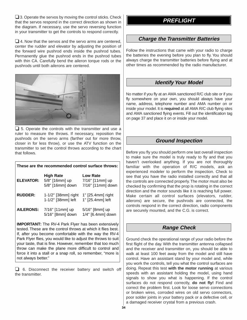
❏ 3. Operate the servos by moving the control sticks. Checkthat the servos respond in the correct direction as shown inthe diagram. If necessary, use the servo reversing functionin your transmitter to get the controls to respond correctly.
❏ 4. Now that the servos and the servo arms are centered,center the rudder and elevator by adjusting the position ofthe forward wire pushrod ends inside the pushrod tubes.Permanently glue the pushrod ends in the pushrod tubeswith thin CA. Carefully bend the aileron torque rods or thepushrods until both ailerons are centered.
❏ 5. Operate the controls with the transmitter and use aruler to measure the throws. If necessary, reposition thepushrods on the servo arms (farther out for more throw,closer in for less throw), or use the ATV function on thetransmitter to set the control throws according to the chartthat follows.
❏ 6. Disconnect the receiver battery and switch offthe transmitter.
Follow the instructions that came with your radio to chargethe batteries the evening before you plan to fly. You shouldalways charge the transmitter batteries before flying and atother times as recommended by the radio manufacturer.
No matter if you fly at an AMA sanctioned R/C club site or if youfly somewhere on your own, you should always have yourname, address, telephone number and AMA number on orinside your model. It is required at all AMA R/C club flying sitesand AMA sanctioned flying events. Fill out the identification tagon page 37 and place it on or inside your model.
Before you fly you should perform one last overall inspectionto make sure the model is truly ready to fly and that youhaven’t overlooked anything. If you are not thoroughlyfamiliar with the operation of R/C models, ask anexperienced modeler to perform the inspection. Check tosee that you have the radio installed correctly and that allthe controls are connected properly. The motor must also bechecked by confirming that the prop is rotating in the correctdirection and the motor sounds like it is reaching full power.Make certain all control surfaces (elevators, rudder,ailerons) are secure, the pushrods are connected, thecontrols respond in the correct direction, radio componentsare securely mounted, and the C.G. is correct.
Ground check the operational range of your radio before thefirst flight of the day. With the transmitter antenna collapsedand the receiver and transmitter on, you should be able towalk at least 100 feet away from the model and still havecontrol. Have an assistant stand by your model and, whileyou work the controls, tell you what the control surfaces aredoing. Repeat this test with the motor running at variousspeeds with an assistant holding the model, using handsignals to show you what is happening. If the controlsurfaces do not respond correctly, do not fly! Find andcorrect the problem first. Look for loose servo connectionsor broken wires, corroded wires on old servo connectors,poor solder joints in your battery pack or a defective cell, ora damaged receiver crystal from a previous crash.
Range Check
Ground Inspection
Identify Your Model
Charge the Transmitter Batteries
PREFLIGHT
These are the recommended control surface throws:
High Rate Low RateELEVATOR: 5/8" [16mm] up 7/16" [11mm] up
5/8" [16mm] down 7/16" [11mm] down
RUDDER: 1-1/2" [38mm] right 1" [25.4mm] right1-1/2" [38mm] left 1" [25.4mm] left
AILERONS: 7/16" [11mm] up 5/16" [8mm] up5/16" [8mm] down 1/4" [6.4mm] down
IMPORTANT: The RV-4 Park Flyer has been extensivelytested. These are the control throws at which it flies best.If, after you become comfortable with the way the RV-4Park Flyer flies, you would like to adjust the throws to suityour taste, that is fine. However, remember that too muchthrow can make the plane more difficult to control andforce it into a stall or a snap roll, so remember, “more isnot always better.”
34

For the longest flight duration, and to get the most from a newbattery, the battery should be cycled. “Cycling” a battery meansto fully charge (“peak” charge) the battery, then to discharge it.Many battery chargers have peak charging and automaticdischarging capabilities. If you do not have a charger that is ableto discharge batteries, you can discharge the battery yourself byrunning the motor with the propeller attached until the propellerbarely continues to turn. Charge and discharge the battery 3 or4 more times on the ground before flying. Be sure to remove thebattery from the airplane between each cycle and allow it to coolbefore recharging.
Lithium batteries do not need to be cycled.
Use fine sandpaper to remove imperfections along theedges of the propeller. For the best performance, use a TopFlite Precision Magnetic Prop Balancer™ (TOPQ5700) tobalance the propellers.
1. Using multiple battery packs for successive flights maycause the motor to become excessively hot, thus causingdamage. Allow the motor to cool for at least 10-20 minutesbetween flights.
2. The ideal power source for the RV-4 Park Flyer system isan 8-cell (9.6 volt) battery pack. The use of a higher voltagebattery may reduce motor life. The recommended motorsare very high performance and care must be taken toprevent the motor from overheating. If a 3-cell LithiumPolymer battery is used, full power must be minimized asthis will over-voltage the motor. For additional suggestionson motor care and lifespan, see the “Decisions You MustMake” section at the front of this manual.
If taking off from the ground, the wheels must spin freely.Check the wheels for binding when moved from side to sideand put a drop of oil on each axle.
Get help from an experienced pilot when learning tooperate motors.
Use safety glasses when running motors.
Do not run the motor in an area of loose gravel or sand; thepropeller may throw such material in your face or eyes.
Keep your face and body as well as all spectators away fromthe path of the propeller as you start and run the motor.
Keep items such as these away from the prop: looseclothing, shirt sleeves, ties, scarfs, long hair or loose objects(pencils, screwdrivers) that may fall out of shirt or jacketpockets into the prop.
The electric motor and battery used in your RV-4 Park Flyerare very powerful and the spinning propeller has a lot ofmomentum; therefore, if you touch the propeller while it isspinning it may inflict severe injury. Respect the motor andpropeller for the damage it is capable of and take whateverprecautions are necessary to avoid injury. Alwaysdisconnect and remove the battery until you are ready to flyagain and always make sure the switches are turned offbefore connecting the battery.
Read and abide by the following Academy of ModelAeronautics Official Safety Code:
GENERAL1. I will not fly my model aircraft in competition or in thepresence of spectators until it has been proven to be airworthyby having been previously successfully flight tested.
2. I will not fly my model aircraft higher than approximately400 feet within 3 miles of an airport without notifying theairport operator. I will give right of way to and avoid flying inthe proximity of full-scale aircraft. Where necessary anobserver shall be utilized to supervise flying to avoid havingmodels fly in the proximity of full-scale aircraft.
3. Where established, I will abide by the safety rules for theflying site I use and I will not willfully and deliberately fly mymodels in a careless, reckless and/or dangerous manner.
7. I will not fly my model unless it is identified with my nameand address or AMA number, on or in the model.
AMA SAFETY CODE (excerpts)
Note: Failure to follow these safety precautions mayresult in severe injury to yourself and others.
MOTOR SAFETY PRECAUTIONS
Oil the Wheels
Motor Care
Examine the Propeller
Cycle the Batteries
PERFORMANCE TIPS
35

RADIO CONTROL1. I will have completed a successful radio equipment groundcheck before the first flight of a new or repaired model.
2. I will not fly my model aircraft in the presence ofspectators until I become a qualified flyer, unless assistedby an experienced helper.
3. I will perform my initial turn after takeoff away from the pit,spectator and parking areas and I will not thereafter performmaneuvers, flights of any sort or landing approaches over apit, spectator or parking area.
4. I will operate my model using only radio control frequenciescurrently allowed by the Federal Communications Commission.
Though the RV-4 Park Flyer is a “Park Flyer,” the best place tofly any model is at an AMA chartered club field. Club fields areset up for R/C flying, making your outing safer and moreenjoyable. We recommend that you join the AMA and a localclub so you can have a safe place to fly and have insurance tocover you in case of a flying accident. The AMA address andtelephone number are in the front of this manual.
If there is no club or R/C flying field in your area, find asuitable site that is clear of trees, telephone poles, buildings,towers, busy streets and other obstacles. Since you are notflying at a sanctioned AMA site, be aware that there may beothers like yourself who could be flying nearby. If both of yourmodels happen to be on the same frequency, interference willlikely cause one or both of the models to crash. An acceptableminimum distance between flying sites is five miles, so keepthis in mind when searching for a flying site.
In addition to obstacles, it is important to be aware of peoplewho may wander into the area once you begin flying. AtAMA club flying sites it is a severe rule infraction to fly overothers, and this is a good practice if flying elsewhere. R/Cmodels tend to attract onlookers whose numbers can soonmultiply, forming small, uncontrolled crowds. Onlookerspose two main problems: First is the danger of actuallycrashing your model into a person, causing injury. Second isthe distraction of those who ask you questions while you aretrying to concentrate on flying. To minimize or avoid thisproblem, have an assistant standing by who can spotpeople who wander into your flying site (so you can avoidflying over them) and who can perform “crowd control” ifpeople start to gather.
IMPORTANT: If you are an inexperienced modeler westrongly urge you to seek the assistance of a competent,experienced R/C pilot to check your model for airworthiness
AND to teach you how to fly. No matter how stable or“forgiving” the RV-4 Park Flyer is, attempting to learn to flyon your own is dangerous and may result in destruction ofyour model or even injury to yourself and others. Therefore,find an instructor and fly only under his or her guidance andsupervision until you have acquired the skills necessary forsafe and fully controlled operation of your model.
We recommend flying the RV-4 Park Flyer when the wind isno greater than ten miles per hour. Less experienced flyersshould fly the RV-4 Park Flyer only in calm (less than onemile per hour) conditions. Frequently, winds are calm in theearly morning and early evening. Often these are the mostenjoyable times to fly anyway!
Until you have the RV-4 Park Flyer properly trimmed for levelflight, we recommend having an assistant hand-launch themodel instead of taking off from the ground.
Turn on the transmitter and plug the battery into the speedcontrol.Turn on the receiver by following the instructions thatcame with your speed control.
IMPORTANT: Confirm that the transmitter operates thecontrols by moving the sticks and watching the surfacesrespond. Occasionally, electric models have been launchedwith the transmitter turned off or the battery disconnectedfrom the speed control!
When ready to launch, the assistant should hold the bottomof the fuselage behind the landing gear, then raise themodel high above his head and point it into the wind. Withthe pilot (that would be you!) standing behind the plane, fullyadvance the throttle to start the motor. As soon as the motoris at full power, the hand launcher should gently toss theplane into the air at a level or slightly nose-up attitude. Becertain the model is being launched into the wind and beimmediately ready to make corrections to keep the airplaneflying straight, level and into the wind.
When the model has gained adequate flying speed under itsown power, gently pull the elevator stick back until theairplane starts a gradual climb. Many beginners tend to pulltoo hard causing the model to stall, so be gentle on theelevator and don’t panic. If you do pull too hard and younotice the model losing speed, release the elevator stickand allow the model to regain airspeed.
Continue a gradual climb and establish a gentle turn (awayfrom yourself) until the airplane reaches an altitude of 75 to100 feet.
The main purpose of the first few flights is to learn how themodel behaves and to adjust the trims for level flight. After
Flight
Takeoff
FLYING
FIND A SAFE PLACE TO FLY
36
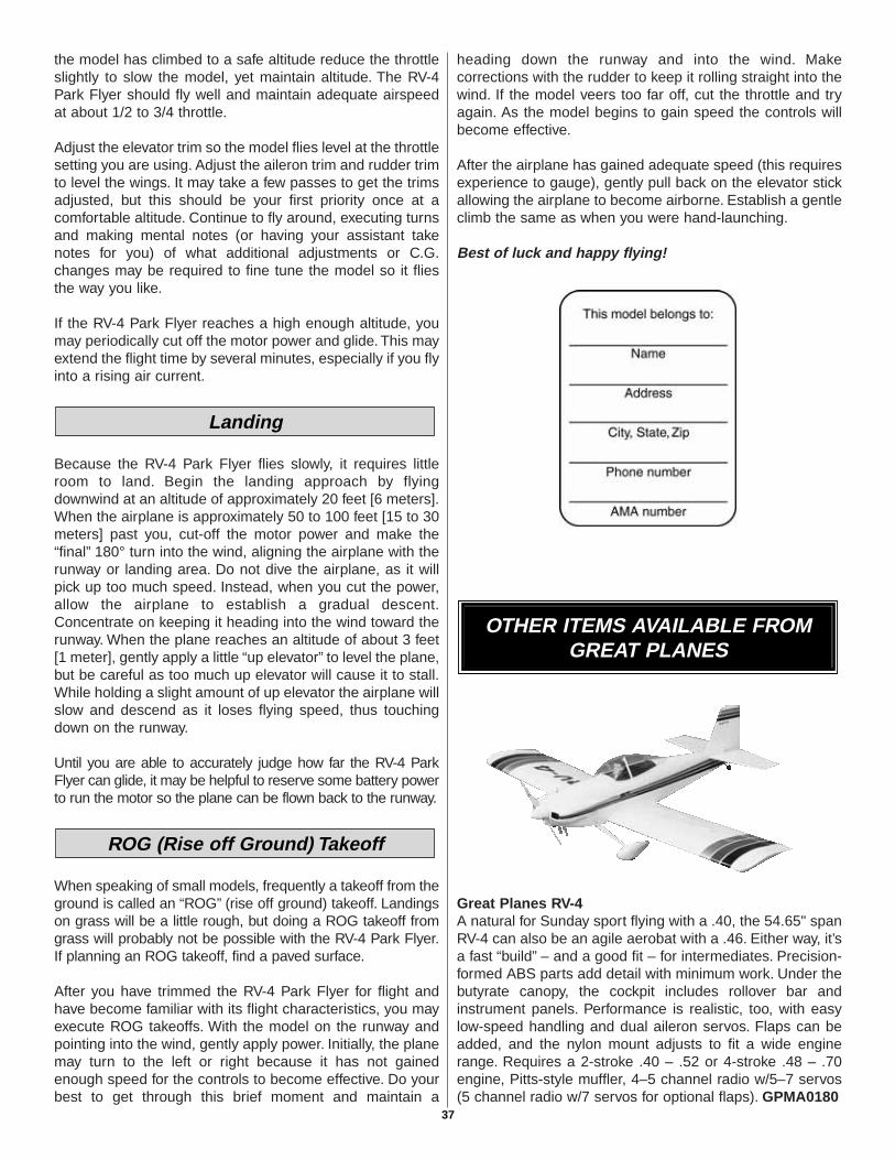
the model has climbed to a safe altitude reduce the throttleslightly to slow the model, yet maintain altitude. The RV-4Park Flyer should fly well and maintain adequate airspeedat about 1/2 to 3/4 throttle.
Adjust the elevator trim so the model flies level at the throttlesetting you are using. Adjust the aileron trim and rudder trimto level the wings. It may take a few passes to get the trimsadjusted, but this should be your first priority once at acomfortable altitude. Continue to fly around, executing turnsand making mental notes (or having your assistant takenotes for you) of what additional adjustments or C.G.changes may be required to fine tune the model so it fliesthe way you like.
If the RV-4 Park Flyer reaches a high enough altitude, youmay periodically cut off the motor power and glide. This mayextend the flight time by several minutes, especially if you flyinto a rising air current.
Because the RV-4 Park Flyer flies slowly, it requires littleroom to land. Begin the landing approach by flyingdownwind at an altitude of approximately 20 feet [6 meters].When the airplane is approximately 50 to 100 feet [15 to 30meters] past you, cut-off the motor power and make the“final” 180° turn into the wind, aligning the airplane with therunway or landing area. Do not dive the airplane, as it willpick up too much speed. Instead, when you cut the power,allow the airplane to establish a gradual descent.Concentrate on keeping it heading into the wind toward therunway. When the plane reaches an altitude of about 3 feet[1 meter], gently apply a little “up elevator” to level the plane,but be careful as too much up elevator will cause it to stall.While holding a slight amount of up elevator the airplane willslow and descend as it loses flying speed, thus touchingdown on the runway.
Until you are able to accurately judge how far the RV-4 ParkFlyer can glide, it may be helpful to reserve some battery powerto run the motor so the plane can be flown back to the runway.
When speaking of small models, frequently a takeoff from theground is called an “ROG” (rise off ground) takeoff. Landingson grass will be a little rough, but doing a ROG takeoff fromgrass will probably not be possible with the RV-4 Park Flyer.If planning an ROG takeoff, find a paved surface.
After you have trimmed the RV-4 Park Flyer for flight andhave become familiar with its flight characteristics, you mayexecute ROG takeoffs. With the model on the runway andpointing into the wind, gently apply power. Initially, the planemay turn to the left or right because it has not gainedenough speed for the controls to become effective. Do yourbest to get through this brief moment and maintain a
heading down the runway and into the wind. Makecorrections with the rudder to keep it rolling straight into thewind. If the model veers too far off, cut the throttle and tryagain. As the model begins to gain speed the controls willbecome effective.
After the airplane has gained adequate speed (this requiresexperience to gauge), gently pull back on the elevator stickallowing the airplane to become airborne. Establish a gentleclimb the same as when you were hand-launching.
Best of luck and happy flying!
Great Planes RV-4 A natural for Sunday sport flying with a .40, the 54.65" spanRV-4 can also be an agile aerobat with a .46. Either way, it’sa fast “build” – and a good fit – for intermediates. Precision-formed ABS parts add detail with minimum work. Under thebutyrate canopy, the cockpit includes rollover bar andinstrument panels. Performance is realistic, too, with easylow-speed handling and dual aileron servos. Flaps can beadded, and the nylon mount adjusts to fit a wide enginerange. Requires a 2-stroke .40 – .52 or 4-stroke .48 – .70engine, Pitts-style muffler, 4–5 channel radio w/5–7 servos(5 channel radio w/7 servos for optional flaps). GPMA0180
OTHER ITEMS AVAILABLE FROMGREAT PLANES
ROG (Rise off Ground) Takeoff
Landing
37
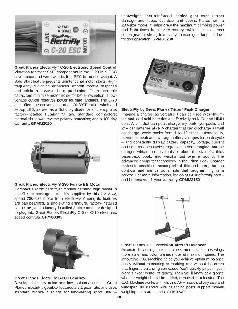
Great Planes ElectriFly™ C-20 Electronic Speed Control Vibration-resistant SMT components in the C-20 Mini ESCsave space and work with built-in BEC to reduce weight. ASafe Start feature prevents unintentional motor starts. High-frequency switching enhances smooth throttle responseand minimizes waste heat production. Three ceramiccapacitors minimize motor noise for better reception; a low-voltage cut-off reserves power for safe landings. The C-20also offers the convenience of an ON/OFF radio switch andset-up LED, as well as a Schottky diode for efficiency, plusfactory-installed Futaba® “J” and standard connectors;thermal shutdown; reverse polarity protection; and a 180-daywarranty. GPMM2020
Great Planes ElectriFly S-280 Ferrite BB Motor Compact electric park flyer models demand high power inan efficient package – and it’s supplied by this 7.2–8.4V,speed 280-size motor from ElectriFly. Among its featuresare ball bearings, a single-wind armature, factory-installedcapacitors, and a factory-installed 2-pin connector designedto plug into Great Planes ElectriFly C-5 or C-10 electronicspeed controls. GPMG0305
Great Planes ElectriFly S-280 Gearbox Developed for low noise and low maintenance, this GreatPlanes ElectriFly gearbox features a 5:1 gear ratio and usesstandard bronze bushings for long-lasting sport use. A
lightweight, fiber-reinforced, sealed gear case resistsdamage and keeps out dust and debris. Paired with a 280-size motor, it helps draw the maximum climbing powerand flight times from every battery mAh. It uses a brasspinion gear for strength and a nylon main gear for quiet, low-friction operation. GPMG0200
ElectriFly by Great Planes Triton™ Peak Charger Imagine a charger so versatile it can be used with lithium-ion and lead-acid batteries as effectively as NiCd and NiMHcells. A unit that can peak charge tiny park flyer packs and24V car batteries alike. A charger that can discharge as wellas charge, cycle packs from 1 to 10 times automatically,memorize peak and average battery voltages for each cycle– and constantly display battery capacity, voltage, currentand time as each cycle progresses. Then, imagine that thecharger, which can do all this, is about the size of a thickpaperback book, and weighs just over a pound. Theadvanced computer technology in the Triton Peak Chargermakes it possible to accomplish all this and more, throughcontrols and menus so simple that programming is abreeze. For more information, log on at www.electrifly.com –and be amazed. 1-year warranty. GPMM3150
Great Planes C.G. Precision Aircraft Balancer™
Accurate balancing makes trainers more stable, low-wingsmore agile, and pylon planes move at maximum speed. Theinnovative C.G. Machine helps you achieve optimum balanceeasily, without measuring or marking–and without the errorsthat fingertip balancing can cause. You’ll quickly pinpoint yourplane’s exact center of gravity. Then you’ll know at a glancewhether weight should be added, removed or relocated. TheC.G. Machine works with kits and ARF models of any size andwingspan. Its slanted wire balancing posts support modelsweighing up to 40 pounds. GPMR2400
38
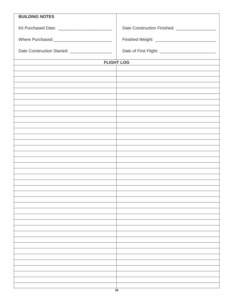
39
BUILDING NOTES
Kit Purchased Date: _______________________
Where Purchased:_________________________
Date Construction Started: __________________
Date Construction Finished: _________________
Finished Weight: __________________________
Date of First Flight: ________________________
FLIGHT LOG
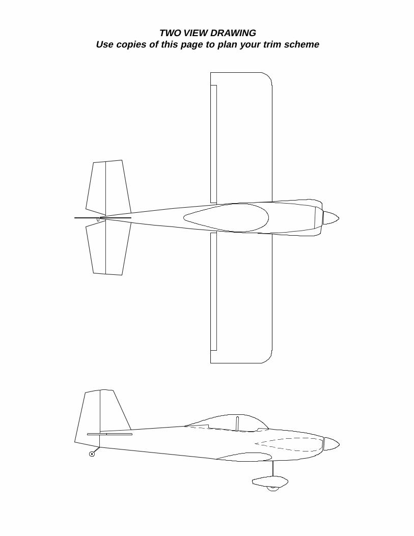
TWO VIEW DRAWINGUse copies of this page to plan your trim scheme
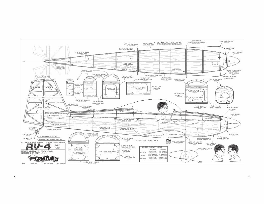
CB
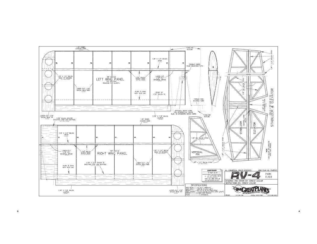
D A
![INSTRUCTION MANUAL - Hobbicomanuals.hobbico.com/gpm/gpma1330-manual-v1_2.pdf · INSTRUCTION MANUAL Length: 60" [1,524mm] Weight: 10.25 lbs ... SAFETY PRECAUTIONS ... Dead Center ™](https://img.pdfslide.us/doc/110x75/5aafd1a47f8b9a59478dd005/instruction-manual-manual-length-60-1524mm-weight-1025-lbs-safety-precautions.jpg)


![INSTRUCTION MANUAL - Hobbicomanuals.hobbico.com/gpm/gpma1030-manual.pdf · · 2013-04-26in this instruction manual. All components must be correctly ... 1/16" [1.6mm], 5/64" [2mm],](https://img.pdfslide.us/doc/110x75/5aa46d307f8b9a2f048c2578/instruction-manual-this-instruction-manual-all-components-must-be-correctly-.jpg)