Embed Size (px)
Citation preview

INSTRUCTION MANUAL(M026B01-03-18A)
Power analyzer
CVM-C5-ITF-485CVM-C5-MC-485CVM-C5-mV-485

2
CVM-C5-xxx-485
Instruction Manual

SAFETY PRECAUTIONS
DISCLAIMER
CIRCUTOR, SA reserves the right to make modifi cations to the device or the unit specifi ca-tions set out in this instruction manual without prior notice�
CIRCUTOR, SA on its web site, supplies its customers with the latest versions of the device specifi cations and the most updated manuals�
www�circutor�com
DANGERWarns of a risk, which could result in personal injury or material damage�
ATTENTIONIndicates that special attention should be paid to a specifi c point�
Follow the warnings described in this manual with the symbols shown below�
If you must handle the unit for its installation, start-up or maintenance, the following should be taken into consideration:
Incorrect handling or installation of the unit may result in injury to personnel as well as damage to the unit� In particular, handling with voltages applied may result in electric shock, which may cause death or serious injury to personnel� Defective installation or maintenance may also lead to the risk of fi re�Read the manual carefully prior to connecting the unit� Follow all installation and maintenance instructions throughout the unit’s working life� Pay special attention to the installation stan-dards of the National Electrical Code�
Refer to the instruction manual before using the unit
In this manual, if the instructions marked with this symbol are not respected or carried out correctly, it can result in injury or damage to the unit and /or installations�
CIRCUTOR, SA reserves the right to modify features or the product manual without prior notifi cation�
3Instruction Manual
CVM-C5-xxx-485
CONTENTS
SAFETY PRECAUTIONS ���������������������������������������������������������������������������������������������������������������������������������������3DISCLAIMER ����������������������������������������������������������������������������������������������������������������������������������������������������������3CONTENTS �������������������������������������������������������������������������������������������������������������������������������������������������������������4REVISION LOG �������������������������������������������������������������������������������������������������������������������������������������������������������61�- VERIFICATION UPON RECEPTION �����������������������������������������������������������������������������������������������������������������72�- PRODUCT DESCRIPTION ��������������������������������������������������������������������������������������������������������������������������������73�- UNIT INSTALLATION ����������������������������������������������������������������������������������������������������������������������������������������8
3�1�- PRIOR RECOMMENDATIONS ��������������������������������������������������������������������������������������������������������������������83�2�- INSTALLATION �������������������������������������������������������������������������������������������������������������������������������������������83�3�- UNIT TERMINALS ���������������������������������������������������������������������������������������������������������������������������������������9
3�3�1�- MODEL CVM-C5-xxx-485-C ��������������������������������������������������������������������������������������������������������������93�3�2�- MODEL CVM-C5-xxx-485-I ��������������������������������������������������������������������������������������������������������������10
3�4�- CONNECTION DIAGRAMS ��������������������������������������������������������������������������������������������������������������������� 113�4�1�- THREE-PHASE NETWORK MEASURING WITH A 4-WIRE CONNECTION, MODEL CVM-C5-IFF-485 and CVM-C5-mV-485� ����������������������������������������������������������������������������������������������������� 113�4�2�- THREE-PHASE NETWORK MEASURING WITH A 4-WIRE CONNECTION, MODEL CVM-C5-MC-485������������������������������������������������������������������������������������������������������������������������������������������123�4�3�- THREE-PHASE NETWORK MEASURING WITH A 3-WIRE CONNECTION, MODELS CVM-C5-ITF-485 AND CVM-C5-mV-485� ���������������������������������������������������������������������������������������������������133�4�4�- THREE-PHASE NETWORK MEASURING WITH A 3-WIRE CONNECTION, MODEL CVM-C5-MC-485������������������������������������������������������������������������������������������������������������������������������������������143�4�5�- THREE-PHASE NETWORK MEASURING WITH A 3-WIRE CONNECTION AND TRANSFORMERS IN AN ARON CONNECTION� ���������������������������������������������������������������������������������������153�4�6�- TWO-PHASE NETWORK MEASURING WITH A 3-WIRE CONNECTION� ������������������������������������163�4�7�- PHASE-TO-PHASE SINGLE-PHASE NETWORK MEASURING WITH A 2-WIRE CONNECTION� ��������������������������������������������������������������������������������������������������������������������������������������������173�4�8�- PHASE-TO-NEUTRAL SINGLE-PHASE NETWORK MEASURING WITH A 2-WIRE CONNECTION ���������������������������������������������������������������������������������������������������������������������������������������������18
4�- OPERATION ���������������������������������������������������������������������������������������������������������������������������������������������������194�1�- MEASURING PARAMETERS �������������������������������������������������������������������������������������������������������������������194�2�- KEYBOARD FUNCTIONS �������������������������������������������������������������������������������������������������������������������������204�3�- DISPLAY ����������������������������������������������������������������������������������������������������������������������������������������������������21
4�3�1� CONSUMPTION DATA AREA �����������������������������������������������������������������������������������������������������������214�3�2� INSTANTANEOUS DATA AREA ��������������������������������������������������������������������������������������������������������24
4�4�- TARIFFS ����������������������������������������������������������������������������������������������������������������������������������������������������274�5�- DIGITAL OUTPUT ( MODEL CVM-C5-xxx-RS485-C) ������������������������������������������������������������������������������274�6�- PROGRAMMING ���������������������������������������������������������������������������������������������������������������������������������������28
4�6�1� PRIMARY VOLTAGE �������������������������������������������������������������������������������������������������������������������������284�6�2� SECONDARY VOLTAGE �������������������������������������������������������������������������������������������������������������������294�6�3� PRIMARY CURRENT ������������������������������������������������������������������������������������������������������������������������294�6�4� SECONDARY CURRENT (ONLY THE MODEL CVM-C5-ITF-485)���������������������������������������������������304�6�5� MEASUREMENT SYSTEM ���������������������������������������������������������������������������������������������������������������304�6�6� RATIO OF KGC02 CARBON EMISSIONS FOR TARIFF 1 ���������������������������������������������������������������314�6�7� COST RATIO FOR TARIFF 1 ������������������������������������������������������������������������������������������������������������314�6�8� RATIO OF KGCO2 CARBON EMISSIONS FOR TARIFF 2 ��������������������������������������������������������������324�6�9� COST RATIO FOR TARIFF 2 ������������������������������������������������������������������������������������������������������������324�6�10� MAXIMUM DEMAND VARIABLE ����������������������������������������������������������������������������������������������������334�6�11� PERIOD OF MAXIMUM DEMAND INTEGRATION �������������������������������������������������������������������������334�6�12� DELETING MAXIMUM DEMAND ����������������������������������������������������������������������������������������������������344�6�13� DEFAULT SCREEN �������������������������������������������������������������������������������������������������������������������������344�6�14� DISPLAY BACKLIGHT ��������������������������������������������������������������������������������������������������������������������344�6�15� PROGRAMMING THE DIGITAL OUTPUT ( MODEL CVM-C-xxx-RS485-C ) �������������������������������354�6�16� DELETING ENERGY METERS �������������������������������������������������������������������������������������������������������394�6�17� DELETING MAXIMUM AND MINIMUM VALUES ���������������������������������������������������������������������������394�6�18� MODBUS COMMUNICATIONS : DEFAULT PARAMETERS ���������������������������������������������������������394�6�19� MODBUS COMMUNICATIONS : PERIPHERAL NUMBER �����������������������������������������������������������394�6�20� MODBUS COMMUNICATIONS : TRANSMISSION SPEED �����������������������������������������������������������404�6�21� MODBUS COMMUNICATIONS : PARITY ���������������������������������������������������������������������������������������404�6�22� MODBUS COMMUNICATIONS : NUMBER OF DATA BITS ���������������������������������������������������������40
4
CVM-C5-xxx-485
Instruction Manual

4�6�23� MODBUS COMMUNICATIONS : NUMBER OF STOP BITS ���������������������������������������������������������414�6�24� LOCKING THE PROGRAMMING ���������������������������������������������������������������������������������������������������414�6�25� PASSWORD ������������������������������������������������������������������������������������������������������������������������������������41
4�7�- COMMUNICATIONS ����������������������������������������������������������������������������������������������������������������������������������42 4�7�1� CONNECTIONS ��������������������������������������������������������������������������������������������������������������������������������������42 4�7�2� PROTOCOL ��������������������������������������������������������������������������������������������������������������������������������������������43 4�7�3� EXEMPLE MODBUS QUESTION ����������������������������������������������������������������������������������������������������������46
5�- TECHNICAL FEATURES ��������������������������������������������������������������������������������������������������������������������������������476�- MAINTENANCE AND TECHNICAL SERVICE ������������������������������������������������������������������������������������������������497�- GUARANTEE ���������������������������������������������������������������������������������������������������������������������������������������������������498�- CE CERTIFICATE ��������������������������������������������������������������������������������������������������������������������������������������������50
5Instruction Manual
CVM-C5-xxx-485

REVISION LOG
Table 1: Revision log�Date Revision Description12/15 M026B01-03-15A Initial Version
01/16 M026B01-03-16A Changes in the following sections:4�- 4�6�15�- 4�7�2�2�
03/16 M026B01-03-16B Changes in the following sections:3�2�- 5�
05/16 M026B01-03-16C Changes in the following sections:4�6�15�- 8�
09/16 M026B01-03-16D Changes in the following sections:2�-4�1-4�6�1
03/18 M026B01-03-18A Changes in the following sections:4�6�15� - 8
Note : Device images are for illustrative purposes only and may differ from the actual device.
6
CVM-C5-xxx-485
Instruction Manual

1�- VERIFICATION UPON RECEPTION
Check the following points when you receive the device:
a) The device meets the specifications described in your order� b) The device has not suffered any damage during transport� c) Perform an external visual inspection of the device prior to switching it on� d) Check that it has been delivered with the following: - An installation guide,
- 2 Retainers for subsequent attachment of the device
If any problem is noticed upon reception, immediately contact the transport company and/or CIRCUTOR's after-sales service�
2�- PRODUCT DESCRIPTION
The CVM-C5-xxx-485 device measures, calculates and displays the main electrical parame-ters of the following low voltage networks: single-phase, two-phase, with and without neutral, balanced three-phase, with ARON measurements or unbalanced� The measurement will be taken in RMS with the three AC voltage inputs and three current inputs�
There are 3 versions of the team based on the current input:
CVM-C5-ITF-485, indirect measure current with transformers /5A and /1A�CVM-C5-MC-485, indirect measure current with efficient transformers series MC1 and MC3�
CVM-C5-mV-485, indirect measure current with transformers /0�333V�
The device features:
- 3 keys that allow you to browse between the various screens and program the device� - LCD Display to display all the parameters, - 1 digital input to select the tariff ( Model CVM-C5-xxx-485-I)� - 1 programmable digital output to act as a pulse or alarm output� ( Model CVM-C5-xxx-485-C) - RS-485 communications, MODBUS RTU©�
7Instruction Manual
CVM-C5-xxx-485

3�- UNIT INSTALLATION
3�1�- PRIOR RECOMMENDATIONS
In order to use the device safely, it is critical that individuals who handle it follow the safety measures described in the standards of the country where it is being used, use the necessary personal protective equipment, and pay attention to the various warnings indicated in this instruction manual�
The CVM-C5 device must be installed by authorised and qualified staff�
The power supply plug must be disconnected and measuring systems switched off before handling, altering the connections or replacing the device� It is dangerous to handle the device while it is powered�
Also, it is critical to keep the cables in perfect condition in order to avoid accidents, personal injury and damage to installations�
The manufacturer of the device is not responsible for any damage resulting from failure by the user or installer to heed the warnings and/or recommendations set out in this manual, nor for damage resulting from the use of non-original products or accessories or those made by other manufacturers�
In the event an anomaly or malfunction is detected in the device, refrain from using it to take any measurements�
Inspect the work area before taking any measurements� Do not take measurements in danger-ous areas or where there is a risk of explosion�
Disconnect the device from the power supply (device and measuring system power supply) before maintaining, repairing or handling the device's connections� Please contact the after-sales service if you suspect that there is an operational fault in the device�
3�2�- INSTALLATION
The device will be installed on a panel (92+0�8 x 92+0�8 mm panel drill hole, in compliance with DIN 43700)� All connections are located inside the electric panel�
Terminals, opening covers or removing elements can expose parts that are haz-ardous to the touch while the device is powered� Do not use the device until it is fully installed�
The device must be connected to a power circuit that is protected with gl (IEC 269) or M type fuses with a rating of 0�5 to 2 A� It must be fitted with a circuit breaker or equivalent device, in order to be able to disconnect the device from the power supply network�
8
CVM-C5-xxx-485
Instruction Manual

The power and voltage measuring circuit must be connected with cables that have a minimum cross-section of 1mm2�
The secondary line of the current transformer will have a minimum cross-section of 2�5 mm2�
The temperature rating of insulation of wires connected to the device will be at minimum 62ºC�
3�3�- UNIT TERMINALS
3�3�1�- MODEL CVM-C5-xxx-485-C
Table 2:List of CVM-C5-xxx-485-C terminals�Device terminals
1 : Auxiliary Power Supply 10: VL3, L3 voltage input2: Auxiliary Power Supply 11: N, neutral3: SO+, Transistor output 12: S1, L1 current input4: SO-, Transistor output 13: S2, L1 current input
5: A(+), RS485 14: S2, L1 current input
6: B(-), RS485 15: S2, L2 current input
7: GND, for RS485 16: S1, L3 current input
8: VL1, L1 voltage input 17: S2, L3 current input
9: VL2, L2 voltage input
1 2 3 4 5 6 7
8 9 10 11 12 13 14 15 16 17
POWER SUPPLY RS485S0+ S0-OUTPUT
S1 S2 S1 S2 S1 S2L1
P1 P2
L2 L3300V ~Ph-NPh-Ph
520V ~
NVL3L2VL1V
P1 P2 P1 P2
A(+)
B(-)
GND
Figure 1: CVM-C5-xxx-485-C terminals�
9Instruction Manual
CVM-C5-xxx-485

3�3�2�- MODEL CVM-C5-xxx-485-I
Table 3:List of CVM-C5-xxx-485-I terminals�Device terminals
1 : Auxiliary Power Supply 10: VL3, L3 voltage input2: Auxiliary Power Supply 11: N, neutral3: Digital input 12: S1, L1 current input4: Digital input 13: S2, L1 current input5: A(+), RS485 14: S2, L1 current input
6: B(-), RS485 15: S2, L2 current input
7: GND, for RS485 16: S1, L3 current input
8: VL1, L1 voltage input 17: S2, L3 current input
9: VL2, L2 voltage input
1 2 3 4 5 6 7
8 9 10 11 12 13 14 15 16 17
POWER SUPPLY RS485
S1 S2 S1 S2 S1 S2L1
P1 P2
L2 L3300V ~Ph-NPh-Ph
520V ~
NVL3L2VL1V
P1 P2 P1 P2
A(+)
B(-)
GND
INPUT
Figure 2: CVM-C5-xxx-485-I terminals�
10
CVM-C5-xxx-485
Instruction Manual

3�4�- CONNECTION DIAGRAMS
3�4�1�- THREE-PHASE NETWORK MEASURING WITH A 4-WIRE CONNECTION, MODEL CVM-C5-IFF-485 AND CVM-C5-mV-485�
Measurement system:
S1 S2
P1 P2S1 S2
P1 P2S1 S2
P1 P2
PowerSupply
VL1 VL2 VL3
L1
L2
L3
ab
A B
ab
A B
POWER SUPPLY S0+ S0-OUTPUT
S1 S2 S1 S2 S1 S2L1
P1 P2
L2 L3300V ~Ph-NPh-Ph
520V ~
NVL3L2VL1V
P1 P2 P1 P2
VL1 VL2 VL3
N
N
RS485
A(+)
B(-)
GND
LOAD
Figure 3:Three-phase measuring with a 4-wire connection, model CVM-C5-ITF-485 and CVM-C5-mV-485�
11Instruction Manual
CVM-C5-xxx-485

3�4�2�- THREE-PHASE NETWORK MEASURING WITH A 4-WIRE CONNECTION, MODEL CVM-C5-MC-485
Measurement system :
PowerSupply
VL1 VL2 VL3
L1
L2
L3
ab
A B
ab
A B
POWER SUPPLY S0+ S0-OUTPUT
S1 S2 S1 S2 S1 S2L1
P1 P2
L2 L3300V ~Ph-NPh-Ph
520V ~
NVL3L2VL1V
P1 P2 P1 P2
VL1 VL2 VL3
N
N
RS485
A(+)
B(-)
GND
LOAD
Brow
n/G
reen
Gre
y/Pi
nk
Gre
en/W
hite
Red/
Blue
1P2
2P2
3P2
1P1
2P1
3P1
Figure 4: Three-phase measuring with a 4-wire connection, model CVM-C5-MC-485�
12
CVM-C5-xxx-485
Instruction Manual

3�4�3�- THREE-PHASE NETWORK MEASURING WITH A 3-WIRE CONNECTION, MODELS CVM-C5-ITF-485 AND CVM-C5-mV-485�
Measurement system:
S1 S2
P1 P2S1 S2
P1 P2S1 S2
P1 P2
PowerSupply
VL1 VL2 VL3
L1
L2
L3
ab
A B
ab
A B
POWER SUPPLY S0+ S0-OUTPUT
S1 S2 S1 S2 S1 S2L1
P1 P2
L2 L3300V ~Ph-NPh-Ph
520V ~
NVL3L2VL1V
P1 P2 P1 P2
VL1 VL2 VL3
RS485
A(+)
B(-)
GND
LOAD
Figure 5: Three-phase measuring with a 3-wire connection, models CVM-C5-ITF-485 and CVM-C5-mV-485�
13Instruction Manual
CVM-C5-xxx-485

3�4�4�- THREE-PHASE NETWORK MEASURING WITH A 3-WIRE CONNECTION , MODEL CVM-C5-MC-485�
Measurement system:
PowerSupply
VL1 VL2 VL3
L1
L2
L3
ab
A B
ab
A B
POWER SUPPLY S0+ S0-OUTPUT
S1 S2 S1 S2 S1 S2L1
P1 P2
L2 L3300V ~Ph-NPh-Ph
520V ~
NVL3L2VL1V
P1 P2 P1 P2
VL1 VL2 VL3
RS485
A(+)
B(-)
GND
LOAD
Brow
n/G
reen
Gre
y/Pi
nk
Gre
en/W
hite
Red/
Blue
1P2
2P2
3P2
1P1
2P1
3P1
Figure 6:Three-phase network measuring with a 3-wire connection, modelo CVM-C5-MC-485�
14
CVM-C5-xxx-485
Instruction Manual

3�4�5�- THREE-PHASE NETWORK MEASURING WITH A 3-WIRE CONNECTION AND TRANSFORMERS IN AN ARON CONNECTION�
Measurement system:
S1 S2
P1 P2
PowerSupply
VL1 VL2 VL3
L1
L2
L3
ab
A B
ab
A B
POWER SUPPLY S0+ S0-OUTPUT
S1 S2 S1 S2 S1 S2L1
P1 P2
L2 L3300V ~Ph-NPh-Ph
520V ~
NVL3L2VL1V
P1 P2 P1 P2
VL1 VL2 VL3
S1 S2
P1 P2
LOAD
RS485
A(+)
B(-)
GND
Figure 7: Three-phase measuring with a 3-wire connection and transformers in an ARON connection�
15Instruction Manual
CVM-C5-xxx-485

3�4�6�- TWO-PHASE NETWORK MEASURING WITH A 3-WIRE CONNECTION�
Measurement system:
S1 S2
P1 P2
PowerSupply
VL1
L1
N
POWER SUPPLY S0+ S0-OUTPUT
S1 S2 S1 S2 S1 S2L1
P1 P2
L2 L3300V ~Ph-NPh-Ph
520V ~
NVL3L2VL1V
P1 P2 P1 P2
VL1
L2S1 S2
P1 P2
VL2
ab
A B
ab
A B
VL2NN
LOAD
RS485
A(+)
B(-)
GND
Figure 8: Two-phase measuring with a 3-wire connection�
16
CVM-C5-xxx-485
Instruction Manual

3�4�7�- PHASE-TO-PHASE SINGLE-PHASE NETWORK MEASURING WITH A 2-WIRE CON-NECTION�
Measurement system:
S1 S2
P1 P2
PowerSupply
VL1
L1
L2
VL2
POWER SUPPLY S0+ S0-OUTPUT
S1 S2 S1 S2 S1 S2L1
P1 P2
L2 L3300V ~Ph-NPh-Ph
520V ~
NVL3L2VL1V
P1 P2 P1 P2
LOAD
RS485
A(+)
B(-)
GND
Figure 9: Phase-to-phase single-phase measuring with a 2-wire connection�
17Instruction Manual
CVM-C5-xxx-485

3�4�8�- PHASE-TO-NEUTRAL SINGLE-PHASE NETWORK MEASURING WITH A 2-WIRE CONNECTION
Measurement system:
S1 S2
P1 P2
Power Supply
VL1
L1
N
POWER SUPPLY S0+ S0-OUTPUT
S1 S2 S1 S2 S1 S2L1
P1 P2
L2 L3300V ~Ph-NPh-Ph
520V ~
NVL3L2VL1V
P1 P2 P1 P2
a b
A B
VL1N
LOAD
RS485
A(+)
B(-)
GND
Figure 10: Phase-to-neutral single-phase measuring with a 2-wire connection�
18
CVM-C5-xxx-485
Instruction Manual

4�- OPERATION
The CVM-C5 is a power analyzer in four quadrants (consumption and generation)�Type of measure
0º
90º
180º
-90º
Capacitive
Capacitive Inductive
Inductive
GenerationPower
ConsumptionPower
Single-phaseThree-phase
Single-phase
Single-phase
Single-phase Three-phase Three-phase
Three-phase
kkk
kk
kkk
kk
kkk
kk
kkk
kk
Figure 11: Four quadrants of CVM-C5�
4�1�- MEASURING PARAMETERS
The device displays the electrical parameters shown in Table 4�Table 4: CVM-5 measuring parameters�
Parameter Units Maximum value
Minimum value
Phase – neutral voltage Vph-n 999�9 10�0Phase-phase voltage Vph-ph 999�9 10�0Current A 9999 0�05Frequency Hz 65 45Active Power kW 9999 0�01Inductive Reactive Power kvarL 9999 0�01Capacitive Reactive Power kvarC 9999 0�01Apparent Power kVA 9999 0�01Power factor PF -0�99 0�99Cos φ φ -0�99 0�99THD % voltage % THD V 999�9 000�0THD % current % THD A 999�9 000�0Total Active Energy Consumed Tariff 1 kWh 999999 000�000Total Active Energy Generated Tariff 1 kWh 999999 000�000Inductive Reactive Energy Consumed Tariff 1 kvarLh 999999 000�000Inductive Reactive Energy Generated Tariff 1 kvarLh 999999 000�000Capacitive Reactive Energy Consumed Tariff 1 kvarch 999999 000�000Capacitive Reactive Energy Generated Tariff 1 kvarch 999999 000�000Total Apparent Energy Tariff 1 kVAh 999999 000�000Total Active Energy Consumed Tariff 2 kWh 999999 000�000Total Active Energy Generated Tariff 2 kWh 999999 000�000
19Instruction Manual
CVM-C5-xxx-485

Table 4 (Continuation): CVM-5 measuring parameters�
Parameter Units Maximum value
Minimum value
Inductive Reactive Energy Consumed Tariff 2 kvarLh 999999 000�000Inductive Reactive Energy Generated Tariff 2 kvarLh 999999 000�000Capacitive Reactive Energy Consumed Tariff 2 kvarch 999999 000�000Capacitive Reactive Energy Generated Tariff 2 kvarch 999999 000�000Total Apparent Energy Tariff 2 kVAh 999999 000�000No� of hours Tariff 1 hours 99999�9 00000�0No� of hours Tariff 2 hours 99999�9 00000�0Cost Tariff 1 COST 9999�99 0000�00Cost Tariff 2 COST 9999�99 0000�00CO2 Emissions Tariff 1 kgCO2 9999�99 0000�00CO2 Emissions Tariff 2 kgCO2 9999�99 0000�00Maximum Demand of Active power kW 9999 0�01Maximum Demand of Apparent Power kVA 9999 0�01Maximum Current Demand A 9999 0�05
4�2�- KEYBOARD FUNCTIONS
The CVM-C5 has 3 keys that allow you to browse between the various screens and program the device�The first keystroke on any of the keys after a period of inactivity switches on the backlight� Key functions on measuring screens (Table 5):
Table 5: Key functions on measuring screens�
Key Short keystroke Long keystroke(2 s)
Previous screen of the in-stant data area Display of minimum value
Next screen of the instant data area Display of maximum value
Browsing the different screens of the consumption data area
Accessing the programming menu
Display of the Maximum Demand programmed and selected�
Key functions in the programming menu (Table 6):Table 6: Key functions in the programming menu�
Key Keystroke
Moves an editable digit (flashing)
Increases the digits (0-9) or rotates between the different options�
Next page
20
CVM-C5-xxx-485
Instruction Manual

4�3�- DISPLAY
The device has a backlit LCD display showing all the parameters listed in Table 4.
The display is divided into two areas (Figure 12):
The consumption data area showing consumption parameters�
The instantaneous data area showing the maximum and minimum instantaneous values being measured or calculated by the device�
Figure 12: CVM-C5 display areas�
4�3�1� CONSUMPTION DATA AREA
The device has 22 different screens in the consumption data area (Table 7)�Table 7: Consumption data area screens�
Screen UnitsTotal active energy generated Tariff 1
kWh
Inductive reactive energy generated Tariff 1
kvarLh
Capacitive reactive energy generated Tariff 1
kvarch
21Instruction Manual
CVM-C5-xxx-485

Table 7 (Continuation): Consumption data area screens�
Screen UnitsTotal apparent energy generated Tariff 1
kVAh
CO2 Emissions Tariff 1
kgCO2
Cost Tariff 1
COST
No� of hours Tariff 1
hours
Total active energy consumed Tariff 1
kWh
Inductive reactive energy consumed Tariff 1
kvarLh
Capacitive reactive energy consumed Tariff 1
kvarch
Total apparent energy consumed Tariff 1
kVAh
Total active energy generated Tariff 2
kWh
Inductive reactive energy generated Tariff 2
kvarLh
Capacitive reactive energy generated Tariff 2
kvarch
Total apparent energy generated Tariff 2
kVAh
22
CVM-C5-xxx-485
Instruction Manual

Table 7 (Continuation): Consumption data area screens�
Screen UnitsCO2 Emissions Tariff 2
kgCO2
Cost Tariff 2
COST
No� of hours Tariff 2
hours
Total active energy consumed Tariff 2
kWh
Inductive reactive energy consumed Tariff 2
kvarLh
Capacitive reactive energy consumed Tariff 2
kvarch
Total apparent energy consumed Tariff 2
kVAh
With the key we can browse between the different screens�
The symbols T1 and T2 that appear on the display indicate the selected tariff and the tariff being displayed, according to Table 10�
23Instruction Manual
CVM-C5-xxx-485

4�3�2� INSTANTANEOUS DATA AREA
To browse through the different screens that appear in the instantaneous data area, you have to use the and keys�
This data area has 13 different screens, Table 8�Table 8: CVM-C5 instantaneous data screens
Measurementsystem Screen Units
Voltage Phase L1- Phase L2Voltage Phase L2- Phase L3Voltage Phase L3- Phase L1
V
Voltage Phase - Neutral L1Voltage Phase - Neutral L2 Voltage Phase - Neutral L3
V
Current L1Current L2Current L3
A
Active power L1Active power L2Active power L3
kW
Apparent power L1Apparent power L2Apparent power L3
kVA
Inductive Reactive Power L1Inductive Reactive Power L2Inductive Reactive Power L3
kvarL
24
CVM-C5-xxx-485
Instruction Manual

Table 8 (Continuation): CVM-C5 instantaneous data screens
Measurementsystem Screen Units
Capacitive Reactive Power L1Capacitive Reactive Power L2Capacitive Reactive Power L3
kvarC
Power factor L1Power factor L2Power factor L3
PF
Active three-phase powerInductive Reactive three-phase Power
Apparent three-phase power
kWkvarLkVA
Active three-phase powerCapacitive Reactive three-phase
Power Apparent three-phase power
kWkvarCkVA
FrequencyCos φ
Hzφ
THD Voltage L1THD Voltage L2THD Voltage L3
THD Current L1THD Current L2THD Current L3
25Instruction Manual
CVM-C5-xxx-485

Also displayed on these screens are:
Maximum values To see the maximum values of the screen being displayed, press the key for 2 seconds� The MAX symbol appears on the display (Figure 13)
Figure 13: Instantaneous data screen displaying maximum values� Minimum values To see the minimum values of the screen being displayed, press the key for 2 seconds� The MIN symbol appears on the display (Figure 14)
Figure 14: Instantaneous data screen displaying minimum values� Maximum Demand The device can calculate the maximum demand of: • Active three-phase power, • Apparent three-phase Power • Current L1, L2 and L3�
Once the parameter to be integrated into the programming menu has been selected ( “4.6.10. Maximum demand variable”), you can display it on the display screen for the parameter by pressing the and keys simultaneously�
The DEM symbol appears on the display and flashes the calculated value of maximum demand (Figure 15)
Figure 15: Instantaneous data screen displaying the maximum demand value�
26
CVM-C5-xxx-485
Instruction Manual

4�4�- TARIFFS
The CVM-C5 has two tariffs, T1 and T2, which can be selected through a Modbus� See “4.7.2.1. Selecting the active tariff“. In the model CVM-C5-xxx-485-I can also be selected tariff via the digital input� Depending on the state of the input, see Table 9�
Table 9: Tariff selection�
Tariff Digital input T1 0T2 1
The symbols T1 and T2 that appear on the display in the consumption data area indicate the selected tariff and the tariff being shown according to Table 10�
Table 10: Displaying tariffs on the display�
Symbol Display Selected tariffT1 flashing Tariff 1 Tariff 1T1 flashingT2 steady Tariff 2 Tariff 1
T1 flashing Tariff 2 Tariff 2T2 flashingT1 steady Tariff 1 Tariff 2
4�5�- DIGITAL OUTPUT ( Model CVM-C5-xxx-RS485-C)
The model CVM-C5-xxx-RS485-C has an optoisolated NPN transistor (terminals 3 and 4 of Figure 1) that may be programmed as:
A pulse output by kWh or kvarh�
An alarm associated with a measurement parameter�
27Instruction Manual
CVM-C5-xxx-485

4�6�- PROGRAMMING
From the programming menu you can:
Define the transformation ratios� Program the ratio of kgCO2 carbon emissions of the two tariffs� Program the cost ratio of the two tariffs� Program the maximum demand parameters� Delete the energy meters and the maximum and minimum values� Modify the display's backlight� Program the digital output� Program the Modbus communications�
The CVM-C5 does not record programming changes until the programming is complete� If the device is RESET before finishing the programming or no key is pressed for 30 seconds, the configuration will not be stored in the memory�
The CVM-C5 does not take any measurements during programming�
To enter the programming menu press the key for 3 seconds�And press to access the first programming point�
4�6�1� PRIMARY VOLTAGE
On this screen the voltage transformer primary is programmed�
To enter or modify the transformer primary value, press the key repeatedly, increasing the value of the flashing digit�When the on-screen value is that desired, press the key to go to the next digit to modify the other values�
If you press the key after changing the last digit, it will jump back to the first digit so you can modify the previously programmed values again�
To validate the information and go to the next programming step, press �
If the value entered is greater than the maximum programming value, the digits flash for 2 seconds and the programmed value is deleted�
Maximum programming value: 01000.Minimum programming value: 0.
28
CVM-C5-xxx-485
Instruction Manual

4�6�2� SECONDARY VOLTAGE
On this screen the voltage transformer secondary is programmed�
To enter or modify the voltage transformer secondary value, press the key repeatedly, increasing the value of the flashing digit�
When the on-screen value is that desired, press the key to go to the next digit and modify the other values�
If you press the key after changing the last digit, it will jump back to the first digit so you can modify the previously programmed values again�
To validate the information and go to the next programming step, press �
If the value entered is greater than the maximum programming value, the digits flash for 2 seconds and the programmed value is deleted�
Maximum programming value: 999.Minimum programming value: 0.
4�6�3� PRIMARY CURRENT
On this screen the current transformer primary is programmed�
To enter or modify the transformer primary value, press the key repeatedly, increasing the value of the flashing digit�When the on-screen value is that desired, press the key to go to the next digit to modify the other values�
If you press the key after changing the last digit, it will jump back to the first digit so you can modify the previously programmed values again�
To validate the information and go to the next programming step, press �
If the value entered is greater than the maximum programming value, the digits flash for 2 seconds and the programmed value is deleted�
Maximum programming value: 9999.Minimum programming value: 0.
29Instruction Manual
CVM-C5-xxx-485

4�6�4� SECONDARY CURRENT (ONLY THE MODEL CVM-C5-ITF-485)
On this screen the current transformer secondary is selected�
Use the key to jump between the two possible options for the current transformer secondary (1 A or 5 A)�
To validate the information and go to the next programming step, press �
Note: If the voltage ratio together with the programmed current ratio exceeds the maximum power value that can be measured by the device, it will return to the primary voltage programming step when you press the key�
Nota : To apply the change to the second current transformer is necessary to reset the computer.
4�6�5� MEASUREMENT SYSTEM
On this screen the measurement system to be used in the installation is selected�
The key jumps between the different options
Three-phase network measuring with a 4-wire connection� Three-phase network measuring with a 3-wire connection�
Three-phase network measuring with a 3-wire connection and transformers in an ARON connection �
Two-phase network measuring with a 3-wire connection� Phase-to-phase single-phase network measuring with a 2-wire connection� Phase-to-neutral single-phase network measuring with a 2-wire connection�
To validate the information and go to the next programming step, press �
30
CVM-C5-xxx-485
Instruction Manual

4�6�6� RATIO OF KGC02 CARBON EMISSIONS FOR TARIFF 1
The carbon emissions ratio is the amount of emissions released into the atmosphere to produce a unit of electricity (1 kWh)�The ratio for the European mix is approximately 0�65 kgCO2 per kWh�
To enter or modify the emissions ratio value, press the key repeatedly, increasing the value of the flashing digit�
When the on-screen value is that desired, press the key to go to the next digit to modify the other values�
If you press the key after changing the last digit, it will jump back to the first digit so you can modify the previously programmed values again�
To validate the information and go to the next programming step, press �
If the value entered is greater than the maximum programming value, the digits flash for 2 seconds and the programmed value is deleted�
Maximum programming value: 9.999.Minimum programming value: 0.
4�6�7� COST RATIO FOR TARIFF 1
On this screen the cost per kWh of electricity of Tariff 1 is programmed�
To enter or modify the cost ratio value, press the key repeatedly, increasing the value of the flashing digit�When the on-screen value is that desired, press the key to go to the next digit to modify the other values�
If you press the key after changing the last digit, it will jump back to the first digit so you can modify the previously programmed values again�
To validate the information and go to the next programming step, press �
If the value entered is greater than the maximum programming value, the digits flash for 2 seconds and the programmed value is deleted�
Maximum programming value: 9.999.Minimum programming value: 0.
31Instruction Manual
CVM-C5-xxx-485

4�6�8� RATIO OF KGCO2 CARBON EMISSIONS FOR TARIFF 2
The carbon emissions ratio is the amount of emissions released into the atmosphere to produce a unit of electricity (1kWh)�The ratio for the European mix is approximately 0�65 kgCO2 per kWh�
To enter or modify the emissions ratio value, press the key repeatedly, increasing the value of the flashing digit�
When the on-screen value is that desired, press the key to go to the next digit to modify the other values�
If you press the key after changing the last digit, it will jump back to the first digit so you can modify the previously programmed values again�
To validate the information and go to the next programming step, press �
If the value entered is greater than the maximum programming value, the digits flash for 2 seconds and the programmed value is deleted�
Maximum programming value: 9.999.Minimum programming value: 0.
4�6�9� COST RATIO FOR TARIFF 2
On this screen the cost per kWh of electricity of Tariff 2 is programmed�
To enter or modify the primary cost ratio value, press the key repeatedly, increasing the value of the flashing digit�When the on-screen value is that desired, press the key to go to the next digit to modify the other values�
If you press the key after changing the last digit, it will jump back to the first digit so you can modify the previously programmed values again�
To validate the information and go to the next programming step, press �If the value entered is greater than the maximum programming value, the digits flash for 2 seconds and the programmed value is deleted�
Maximum programming value: 9.999.Minimum programming value: 0.
32
CVM-C5-xxx-485
Instruction Manual
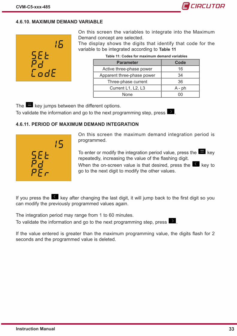
4�6�10� MAXIMUM DEMAND VARIABLE
On this screen the variables to integrate into the Maximum Demand concept are selected�The display shows the digits that identify that code for the variable to be integrated according to Table 11
Table 11: Codes for maximum demand variables
Parameter CodeActive three-phase power 16
Apparent three-phase power 34Three-phase current 36Current L1, L2, L3 A - ph
None 00
The key jumps between the different options�To validate the information and go to the next programming step, press �
4�6�11� PERIOD OF MAXIMUM DEMAND INTEGRATION
On this screen the maximum demand integration period is programmed�
To enter or modify the integration period value, press the key repeatedly, increasing the value of the flashing digit�When the on-screen value is that desired, press the key to go to the next digit to modify the other values�
If you press the key after changing the last digit, it will jump back to the first digit so you can modify the previously programmed values again�
The integration period may range from 1 to 60 minutes�To validate the information and go to the next programming step, press �
If the value entered is greater than the maximum programming value, the digits flash for 2 seconds and the programmed value is deleted�
33Instruction Manual
CVM-C5-xxx-485

4�6�12� DELETING MAXIMUM DEMAND
On this screen you select whether or not to delete the maximum demand�
Use the key to jump between the two options (Yes and No)�
To validate the information and go to the next programming step, press �
4�6�13� DEFAULT SCREEN
On this screen the default or start-up instantaneous data screen (Table 8) for the CVM-C5 is selected�
Press the key repeatedly until you see the default screen of your choice�To validate the screen and go to the next programming step, press �
The electrical parameters may also be displayed by automatically rotating through the 7 instantaneous data screens in 5-second intervals�To do so press the key repeatedly until the parameters flash;To validate the rotating screen function and go to the next programming step, press �
4�6�14� DISPLAY BACKLIGHT
On this screen the time that the Backlight will stay lit (in seconds) after the last keystroke on the unit is programmed�
To enter or modify the backlight value, press the key repeatedly, increasing the value of the flashing digit�
When the on-screen value is that desired, press the key to go to the next digit to modify the other values�
The value 00 indicates that the backlight will stay permanently lit�The backlight time may range from 5 to 99 seconds�
To validate the information and go to the next programming step, press �
34
CVM-C5-xxx-485
Instruction Manual

4�6�15� PROGRAMMING THE DIGITAL OUTPUT ( MODEL CVM-C-xxx-RS485-C )
The CVM-C5 digital output may be programmed as:
Pulse by n kWh or kvarh (Energy): the value corresponding to the energy consumed or generated may be programmed, to generate a pulse�
Alarm condition: a magnitude may be associated with the digital output, setting a maximum, minimum and delay value for the trip condition�
If you do not wish to program a variable, put 00 and validate with the key�
Pulse programming by n kWh or kvarh
On this screen the energy code is selected based on Table 12 for the energy you want the pulse output to generate�
The key jumps between the different options�
Table 12: Codes for the different energy types�
Parameter CodeActive Energy III Tariff 1 31Inductive Reactive Energy III Tariff 1 32Capacitive Reactive Energy III Tariff 1 33Apparent Energy III Tariff 1 48Active Energy III Generated Tariff 1 49Inductive Reactive Energy III Generated Tariff 1 50Capacitive Reactive Energy III Generated Tariff 1 51Apparent Energy III Generated Tariff 1 52Active Energy III Tariff 2 55Inductive Reactive Energy III Tariff 2 56Capacitive Reactive Energy III Tariff 2 57Apparent Energy III Tariff 2 58Active Energy III Generated Tariff 2 59Inductive Reactive Energy III Generated Tariff 2 60Capacitive Reactive Energy III Generated Tariff 2 61Apparent Energy III Generated Tariff 2 62Active Energy Consumed (Regardless of the tariff selected) 99
Once an Energy code has been selected and validated using the key you must enter the kilowatts per pulse�
35Instruction Manual
CVM-C5-xxx-485

To enter or modify the kilowatts per pulse value, press the key repeatedly, increasing the value of the flashing digit�When the on-screen value is that desired, press the key to go to the next digit to modify the other values�
If you press the key after changing the last digit, it will jump back to the first digit so you can modify the previously programmed values again�Example: To program 500 Wh per pulse: 000.500 To program 1.5 kWh per pulse: 001.500
Once the desired option has been programmed, press the key to validate the information and thereby finish programming the device�
Maximum programming value: 999999 KWh.Minimum programming value: 000.001 KWh.
Programming by alarm condition
On this screen the parameter code for which you want an alarm to be generated is selected, based on Table 13�
The key jumps between the different options�
Table 13: Parameter codes for alarm programming�
Parameter Code Parameter CodeVoltage Phase - Neutral L1 01 THD voltage L3 27Current L1 02 THD current L3 30Active power L1 03 Active three-phase power 16Inductive / Capative reactive power L1 04 Inductive Reactive three-phase power 17Power factor L1 05 Capacitive Reactive three-phase power 18THD voltage L1 25 Apparent three-phase power 34THD current L1 28 Maximum demand 35Voltage Phase - Neutral L2 06 Three-phase current 36Current L2 07 Cos φ 19Active power L2 08 Three-phase Power factor 20Inductive / Capative reactive power L2 09 Frequency 21Power factor L2 10 Voltage L1 - L2 22THD voltage L2 26 Voltage L2 - L3 23THD current L2 29 Voltage L3 - L1 24Voltage Phase - Neutral L3 11 Maximum demand L1 (1) 35Current L3 12 Maximum demand L2 (1) 42
36
CVM-C5-xxx-485
Instruction Manual

Table 13 (Continuation): Parameter codes for alarm programming�
Parameter Code Parameter CodeActive power L3 13 Power factor L3 15Inductive / Capative reactive power L3 14 Maximum demand L3 (1) 43(1) Parameter valid only if programmed the maximum demand current per phase�
In addition, there are some parameters (Table 14) that refer to the three phases at the same time (OR function)� If you have selected one of these variables, the alarm will be activated when any of the three phases meets the programmed conditions�
Table 14:Multiple parameter codes for alarm programming�
Parameter CodeVoltages Phase - Neutral 85Currents 86Active powers 87Reactive powers 88Power factor 89Voltages Phase-Phase 90THD V 91THD A 92
Once an alarm code has been selected and validated with the key you must enter the maximum value of the alarm condition�
The maximum value: above this value the transistor is closed�To enter or modify the maximum value, press the key repeatedly, increasing the value of the flashing digit�When the on-screen value is that desired, press the key to go to the next digit to modify the other values�
If you press the key after modifying the last digit the decimal point position will be programmed�To validate the information and proceed to programming the minimum value, press �
The minimum value: below this value the transistor is closed�To enter or modify the minimum value, press the key repeatedly, increasing the value of the flashing digit�When the on-screen value is that desired, press the key to go to the next digit to modify the other values�
If you press the key after modifying the last digit the decimal point position will be programmed�
To validate the information and proceed to programming the delay value, press �
37Instruction Manual
CVM-C5-xxx-485

This is where the device's connection and disconnection delay (in seconds) are programmed�To enter or modify the delay value, press the key repeatedly, increasing the value of the flashing digit�When the on-screen value is that desired, press the key to go to the next digit to modify the other values�
Once the delay has been programmed, press the key to go to the next programming step�In Table 15 we can see the functioning of the digital output based on the programmed maxi-mum and minimum values�
Table 15: Functioning of the digital output based on the programmed maximum and minimum values�
Minimum value Maximum value� Condition Digital output functioning
Positive Positive MAX > MIN
Positive Positive MAX < MIN
Negative Positive
Positive Negative
Negative Negative MAX > MIN
Negative Negative MAX < MIN
38
CVM-C5-xxx-485
Instruction Manual

4�6�16� DELETING ENERGY METERS
On this screen you select whether or not to delete the energy meters�
Use the key to jump between the two options (Yes and No)�
To validate the information and go to the next programming step, press �
4�6�17� DELETING MAXIMUM AND MINIMUM VALUES
On this screen you select whether or not to delete the maximum and minimum values
Use the key to jump between the two options (Yes and No)�
To validate the information and go to the next programming step, press �
4�6�18� MODBUS COMMUNICATIONS : DEFAULT PARAMETERS
On this screen you select whether we want to return to the default parameters of the Modbus communications�Default parameters:Peripheral number : 1Transmission speed : 9600Parity : NoNumber of data bits : 8Number of Stop bits : 1
Use the key to jump between the two options: Yes or No
If you select the Yes option, the device jumps to step programming “4.6.24. Locking the programming”To validate the information and go to the next programming step, press �
4�6�19� MODBUS COMMUNICATIONS : PERIPHERAL NUMBER
The peripheral number is programmed on this screen�
To enter or modify the delay value, press the key repeatedly, increasing the value of the flashing digit�
39Instruction Manual
CVM-C5-xxx-485

When the on-screen value is that desired, press the key to go to the next digit to modify the other values�To validate the information and go to the next programming step, press �
The peripheral number ranges from 0 to 255�
4�6�20� MODBUS COMMUNICATIONS : TRANSMISSION SPEED
The transmission speed of modbus communications is programmed on this screen�
The different options are: 1200, 2400, 4800, 9600 o 19200�
The key jumps between the different options�
To validate the information and go to the next programming step, press �
4�6�21� MODBUS COMMUNICATIONS : PARITY
The type of parity of Modbus communications is selected on this screen�The key jumps between the different options�no , no parityEUEn, even parity�odd, odd parity�
�To validate the information and go to the next programming step, press �
4�6�22� MODBUS COMMUNICATIONS : NUMBER OF DATA BITS
The number of data bits of Modbus communications are displayed on this screen: 8 bits�
This parameter is not configurable�
To go to the next programming step, press �
40
CVM-C5-xxx-485
Instruction Manual

4�6�23� MODBUS COMMUNICATIONS : NUMBER OF STOP BITS
The number of Stop bits of Modbus communications are programmed on this screen�
Press key to browse the options: 1 or 2 bits�
To validate the information and go to the next programming step, press �
4�6�24� LOCKING THE PROGRAMMING
This screen is for protecting the data configured in the programming menu�
Use the key to jump between the two options:
When you enter the programming menu you can view and modify the programming�
When you enter the programming you can view the programming but not modify it� � In order to modify the programming you need to enter a password�
To validate the information and go to the next programming step, press �
4�6�25� PASSWORD
On this screen the password to modify the programming parameters is programmed�
To enter or modify the value, press the key repeatedly, increasing the value of the flashing digit�
When the on-screen value is that desired, press the key to go to the next digit to modify the other values�
Default value: 1234.
Press the key to finish programming the device�
41Instruction Manual
CVM-C5-xxx-485

4�7�- COMMUNICATIONS
The CVM-C5 have one RS-485 communications port, with MODBUS RTU ® protocol�
4�7�1� CONNECTIONS
The RS-485 cable must be wired with twisted pair cable with mesh shield (minimum 3 wires), with a maximum distance between the CVM-C5 and the master unit of 1200 metres�A maximum of 32 CVM-C5 units can be connected to this bus�
Use an intelligent RS-232 to RS-485 network protocol converter to establish the communications with the master unit�
B(-)A(+)
A(+
)
B(-) S
S
RS-232 / USB / Ethernet / Profibus ...
PC
RS-485
RS-485
RS-232USBEthernetProfibus...
POWER SUPPLY S0+ S0-OUTPUT
S1 S2 S1 S2 S1 S2L1
P1 P2
L2 L3300V ~Ph-NPh-Ph
520V ~
NVL3L2VL1V
P1 P2 P1 P2
RS485
A(+)
B(-)
GND
Figure 16: RS-485 Connection diagram�
42
CVM-C5-xxx-485
Instruction Manual

4�7�2� PROTOCOL
In the Modbus protocol, the CVM-C5 unit uses the RTU (Remote Terminal Unit) mode�
The Modbus functions implemented in the unit are as follows:
Function 03 and 04� Reading n Words (2 bytes)� Function used for reading the parameters being measured by the CVM-C5� All parameters are 32-bits long, which is why to ask each parameter takes two Words�
Function 10� Writing multiple logs�
4�7�2�1� Selecting the active tariff
The CVM-C5 has two tariffs, T1 and T2, selectable using the following Modbus function:
Selecting the active tariff:
Address Function Registro inicial No registers No bytes Tariff CRC
NP(1) 10 1388 0001 02 000T(2) xxxx
(1) NP : Peripheral number(2) The selection of the active tariff is selected according to the following table:
Table 16:Selecting tariff�
Code Tariff0 Tariff T11 Tariff T2
Response:
Address Function Initial register No registers CRC
NP(1) 10 1388 0001 xxxx
reading active tariff:
Address Function Initial register No registers CRC
NP(1) 04 1388 0001 xxxx
Response:
Address Function No bytes No registers CRC
NP(1) 04 02 000T(2) xxxx
43Instruction Manual
CVM-C5-xxx-485

4�7�2�2� Measurement variables�
All the adresses of Modbus memory are in Hexadecimal�For these variables is implemented the Function 0x03 and 0x04�
Table 17: Modbus memory map ( Table 1)
Parameter Symbol Instantaneous Maximum Mínimum UnitsL1 Phase-Neutral voltage V 1 00-01 84-85 100-101 V x 10L1 Current A 1 02-03 86-87 102-103 mAL1 Active Power kW 1 04-05 88-89 104-105 WL1 Reactive Power kvar 1 06-07 8A-8B 106-107 varL1 Inductive Reactive Power kvarL1 17C-17D 18E-18F 1A0-1A1 varL1 Capacitive Reactive Power kvarC1 182-183 194-195 1A6-1A7 varL1 Apparent Power kVAL1 188-189 19A-19B 1AC-1AD VAL1 Power Factor PF 1 08-09 8C-8D 108-109 x100L2 Phase-Neutral voltage V 2 0A-0B 8E-8F 10A-10B V x 10L2 Current A 2 0C-0D 90-91 10C-10D mAL2 Active Power kW 2 0E-0F 92-93 10E-10F WL2 Reactive Power kvar 2 10-11 94-95 110-111 varL2 Inductive Reactive Power kvarL2 17E-17F 190-191 1A2-1A3 varL2 Capacitive Reactive Power kvarC2 184-185 196-197 1A8-1A9 varL2 Apparent Power kVAL2 18A-18B 19C-19D 1AE-1AF VAL2 Power Factor PF 1 12-13 96-97 112-113 x100L3 Phase-Neutral voltage V 3 14-15 98-99 114-115 V x 10L3 Current A 3 16-17 9A-9B 116-117 mAL3 Active Power kW 3 18-19 9C-9D 118-119 WL3 Reactive Power kvar 3 1A-1B 9E-9F 11A-11B varL3 Inductive Reactive Power kvarL3 180-181 192-193 1A4-1A5 varL3 Capacitive Reactive Power kvarC3 186-187 198-199 1AA-1AB varL3 Apparent Power kVAL3 18C-18D 19E-19F 1B0-1B1 VAL3 Power Factor PF 3 1C-1D A0-A1 11C-11D x100Three-phase Active power kW III 1E-1F A2-A3 11E-11F WThree-phase Inductive Power kvarL III 20-21 A4-A5 120-121 varThree-phase Capacitive Power kvarL III 22-23 A6-A7 122-123 varThree-phase Cos φ Cos φ III 24-25 A8-A9 124-125 x100Three-phase Power Factor PF III 26-27 AA-AB 126-127 x100Frequency Hz 28-29 AC-AD 128-129 Hz x 10L1 - L2 Voltage V12 2A-2B AE-AF 12A-12B V x 10L2 - L3 Voltage V23 2C-2D B0-B1 12C-12D V x 10L3 - L1 Voltage V31 2E-2F B2-B3 12E-12F V x 10THD Voltage L1 %THDV1 30-31 B4-B5 130-131 % x 10THD Voltage L2 %THDV2 32-33 B6-B7 132-133 % x 10THD Voltage L3 %THDV3 34-35 B8-B9 134-135 % x 10THD Current L1 %THDI1 36-37 BA-BB 136-137 % x 10THD Current L2 %THDI2 38-39 BC-BD 138-139 % x 10THD Current L3 %THDI3 3A-3B BE-BF 13A-13B % x 10Three-phase Apparent Power kvaIII 42-43 C6-C7 142-143 VAMaximum demand Md(Pd) 44-45 C8-C9 - W/VA/mA
44
CVM-C5-xxx-485
Instruction Manual

Parameter Symbol Instantaneous Maximum Mínimum UnitsThree-phase current (average) I_AVG 46-47 CA-CB 146-147 mAMaximum demand I2 Md (Pd) 52-53 D6-D7 - mAMaximum demand I3 Md (Pd) 54-55 D8-D9 - mAPhase-Phase voltage (average) VF-AVG 56-57 DA-DB 156-157 V x 10Phase-Neutral voltage (average) VL-AVG 58-59 DC-DD 158-159 V x 10
4�7�2�3� Energy variables
All the adresses of Modbus memory are in Hexadecimal�For these variables is implemented the Function 0x03 and 0x04�
Table 18: Modbus memory map ( Table 2)�
Parameter Symbol Tariff 1 Tariff 2 UnitsActive energy kWh III 3C-3D 6C-6D Whinductive reactive energy (kvarhL) kvarhL III 3E-3F 6E-6F varhcapacitive reactive energy (kvarhC) kvarhC III 40-41 70-71 varhapparent energy (kVAh) kVAh III 5E-5F 72-73 kVAhGenerated active energy kWh III (-) 60-61 74-75 WhGenerated inductive reactive energy kvarhL III (-) 62-63 76-77 varhGenerated capacitive reactive energy kvarhC III 64-65 78-79 varhGenerated apparent energy kVAh III 66-67 7A-7B VAhCO2 emissions KgCO2 68-69 7C-7D KgCO2 x 100000Generation Cost $ 6A-6B 7E-7F $ x 100000Hours per tariff Hours 80-81 82-83 seg
45Instruction Manual
CVM-C5-xxx-485

4�7�3� EXEMPLE MODBUS QUESTION
Question: Value of the Phase L1 - Phase L2 voltage
Address Function Initial register No register CRC
0A 04 2A 0002 xxxx
Address: 0A, Peripheral number: 10 in decimals� Function: 04, Read function� Initial register: 2A, register on which the reading will start� No� of registers: 0002, number of registers read� CRC: xxxx, CRC Character�
Response:
Address Function No Bytes Register no 1
Registerno 2 CRC
0A 04 04 0000 084D xxxx
Address: 0A, Responding peripheral number: 10 in decimals� Function: 04, Read function� No� of bytes: 04, No� of bytes received� Register: 0000084D, Value of the Phase L1 - Phase L2 voltage: V12 x 10 : 212�5 V CRC: xxxx, CRC Character�
Note: Every Modbus frame has a maximum limit of 20 variables (40 register).
46
CVM-C5-xxx-485
Instruction Manual

5�- TECHNICAL FEATURESAC Power supply
Rated voltage 95 ��� 240 V~ ± 10%
Frequency 50 ��� 60 Hz
Consumption 3�5��� 6 VA
Installation category CAT III 300V
DC Power supplyRated voltage 105 ��� 272 V ± 10%Consumption 2 ��� 6W
Installation category CAT III 300V
Voltage measurement circuit Nominal voltage (Un) 300V P-N, 520V P-P
Voltage measurement margin 5 ��� 120% UnFrequency measurement margin 45 ��� 65HzInput impedance 440 kΩMin� voltage measurement (Vstart) 10V P-N
Installation category CAT III 300V
Current measurement circuit Model CVM-C5-ITF-485 CVM-C5-MC-485 CVM-C5-mV-485
Nominal current (In) ���/5A o ���/1A ���/0�250 A ���/0�333 A Current measurement margin 5 ���110% In 5 ���110% In 5 ���110% InMaximum current, impulse < 1s 100 A 100 A 1�2 In
Minimum current measurement (Istart) 10 mA
MC1 MC36�66 mA
0�25 A 0�12 AInstallation Category CAT III 300V CAT III 300V CAT III 300V
Measurement accuracyModel CVM-C5-ITF-485 CVM-C5-MC-485 CVM-C5-mV-485Voltage measurement 0�5% 0�5% 1%Current measurement 0�5% ± 1 digit 0�5% ± 1 digit 1% Power measurement 1% ± 1 digit 1% ± 1 digit 2% Active energy measurement Class 1 Class 1 Class 2Reactive energy measurement Class 1 Class 1 Class 2
CommunicationsBus RS-485Protocol Modbus RTUBaud rate 1200 - 2400 - 4800 - 9600 - 19200Stop bits 1 - 2Parity without - even - odd
Pulse output ( CVM-C5-xxx-RS485-C) (1)
Type NPNMaximum voltage 24 V Maximum current 50 mAMaximum frequency 5 pulses / sec
47Instruction Manual
CVM-C5-xxx-485

(Continuation) Pulse output (CVM-C5-xxx-RS485-C) (1)
Minimum pulse width 100 ms (Ton: 100 ms, Toff: 100 ms)
Digital input (CVM-C5-xxx-RS485-I) (1)
Type Potential free contactInsulation Optoisolated
(1) Must be connected to SELV circuit�User interface
Display LCD (60x54mm)Keyboard 3 keys
Environmental featuresOperating temperature -5ºC��� +45ºCStorage temperature -10ºC ��� +50ºCRelative humidity (non-condensing) 5 ��� 95%Maximum altitude 2000 m
Protection degree (2) IP31 Front panel: IP51
(2) This pollution degree hasn’t been tested by UL�Mechanical features
Dimensions ( Figure 16) 96�7x96�7x62�6 mm Weight 480 grEnclosure V0 self-extinguishing plasticAttachment Panel
62.6
9.9 50
91.8
2.7
96.7
96.7
Figure 17:Dimensions�
StandardsSafety of electronic measuring units IEC 61010: 2010Electromagnetic compatibility (CEM)� Part 6-4: Generic standards� Emissions standard for industrial environments� UNE-EN 61000-6-4:2007
Electromagnetic compatibility (CEM)� Part 6-2: Generic standards� Immunity for industrial environments� UNE-EN 61000-6-2:2006
Safety requirements for electrical equipment for measurement, control, and laboratory use - Part 1: General requirements UL/CSA 61010-1 3rd edition
48
CVM-C5-xxx-485
Instruction Manual

6�- MAINTENANCE AND TECHNICAL SERVICE
7�- GUARANTEE
• No returns will be accepted and no unit will be repaired or replaced if it is not ac-companied by a report indicating the defect detected or the reason for the return�•The guarantee will be void if the units has been improperly used or the stora-ge, installation and maintenance instructions listed in this manual have not been followed� “Improper usage” is defi ned as any operating or storage condition con-trary to the national electrical code or that surpasses the limits indicated in the technical and environmental features of this manual�• CIRCUTOR accepts no liability due to the possible damage to the unit or other parts of the installation, nor will it cover any possible sanctions derived from a pos-sible failure, improper installation or “improper usage” of the unit� Consequently, this guarantee does not apply to failures occurring in the following cases:- Overvoltages and/or electrical disturbances in the supply;- Water, if the product does not have the appropriate IP classifi cation;- Poor ventilation and/or excessive temperatures;- Improper installation and/or lack of maintenance;- Buyer repairs or modifi cations without the manufacturer’s authorisation�
CIRCUTOR guarantees its products against any manufacturing defect for two years after the delivery of the units�
CIRCUTOR will repair or replace any defective factory product returned during the guarantee period�
In the case of any query in relation to unit operation or malfunction, please contact the CIRCUTOR, SA Technical Support Service�
Technical Assistance ServiceVial Sant Jordi, s/n, 08232 - Viladecavalls (Barcelona)Tel: 902 449 459 ( España) / +34 937 452 919 (outside of Spain)email: sat@circutor�es
49Instruction Manual
CVM-C5-xxx-485
8�- CE CERTIFICATE
50
CVM-C5-xxx-485
Instruction Manual
51Instruction Manual
CVM-C5-xxx-485

52
CVM-C5-xxx-485
Instruction Manual

53Instruction Manual
CVM-C5-xxx-485

CIRCUTOR, SA Vial Sant Jordi, s/n08232 -Viladecavalls (Barcelona)Tel.: (+34) 93 745 29 00 - Fax: (+34) 93 745 29 14 www.circutor.com [email protected]